EP2889999A1 - Methods of torque estimation and compensation and systems thereof - Google Patents
Methods of torque estimation and compensation and systems thereof Download PDFInfo
- Publication number
- EP2889999A1 EP2889999A1 EP14195712.6A EP14195712A EP2889999A1 EP 2889999 A1 EP2889999 A1 EP 2889999A1 EP 14195712 A EP14195712 A EP 14195712A EP 2889999 A1 EP2889999 A1 EP 2889999A1
- Authority
- EP
- European Patent Office
- Prior art keywords
- torque
- machine
- voltage
- estimated
- torque command
- Prior art date
- Legal status (The legal status is an assumption and is not a legal conclusion. Google has not performed a legal analysis and makes no representation as to the accuracy of the status listed.)
- Granted
Links
- 238000000034 method Methods 0.000 title claims abstract description 48
- 238000012512 characterization method Methods 0.000 claims abstract description 18
- 230000001131 transforming effect Effects 0.000 claims abstract description 7
- 229920006395 saturated elastomer Polymers 0.000 claims description 17
- 238000001914 filtration Methods 0.000 claims description 11
- 238000005070 sampling Methods 0.000 claims description 7
- 238000004804 winding Methods 0.000 abstract description 13
- 238000012545 processing Methods 0.000 description 38
- 230000009466 transformation Effects 0.000 description 21
- 238000004364 calculation method Methods 0.000 description 15
- 238000012360 testing method Methods 0.000 description 12
- 238000013500 data storage Methods 0.000 description 8
- 230000003287 optical effect Effects 0.000 description 8
- 230000006870 function Effects 0.000 description 6
- 239000004065 semiconductor Substances 0.000 description 6
- 230000004907 flux Effects 0.000 description 5
- 230000015654 memory Effects 0.000 description 5
- 230000010355 oscillation Effects 0.000 description 5
- 230000001360 synchronised effect Effects 0.000 description 5
- 238000012935 Averaging Methods 0.000 description 4
- 241000607479 Yersinia pestis Species 0.000 description 4
- 230000008859 change Effects 0.000 description 4
- 238000010586 diagram Methods 0.000 description 4
- 238000005259 measurement Methods 0.000 description 4
- 238000007493 shaping process Methods 0.000 description 4
- 229910000831 Steel Inorganic materials 0.000 description 3
- 238000004891 communication Methods 0.000 description 3
- 238000000605 extraction Methods 0.000 description 3
- 238000010438 heat treatment Methods 0.000 description 3
- 238000004519 manufacturing process Methods 0.000 description 3
- 238000012986 modification Methods 0.000 description 3
- 230000004048 modification Effects 0.000 description 3
- 230000007935 neutral effect Effects 0.000 description 3
- 239000010959 steel Substances 0.000 description 3
- 230000006399 behavior Effects 0.000 description 2
- 230000005540 biological transmission Effects 0.000 description 2
- 238000006243 chemical reaction Methods 0.000 description 2
- 230000001419 dependent effect Effects 0.000 description 2
- 238000013461 design Methods 0.000 description 2
- 230000000694 effects Effects 0.000 description 2
- 230000008569 process Effects 0.000 description 2
- 230000000630 rising effect Effects 0.000 description 2
- 230000003313 weakening effect Effects 0.000 description 2
- RYGMFSIKBFXOCR-UHFFFAOYSA-N Copper Chemical compound [Cu] RYGMFSIKBFXOCR-UHFFFAOYSA-N 0.000 description 1
- 230000005355 Hall effect Effects 0.000 description 1
- 230000002159 abnormal effect Effects 0.000 description 1
- 230000005534 acoustic noise Effects 0.000 description 1
- 230000009471 action Effects 0.000 description 1
- 238000004378 air conditioning Methods 0.000 description 1
- 238000003491 array Methods 0.000 description 1
- 238000001816 cooling Methods 0.000 description 1
- 229910052802 copper Inorganic materials 0.000 description 1
- 239000010949 copper Substances 0.000 description 1
- 238000012937 correction Methods 0.000 description 1
- 230000003247 decreasing effect Effects 0.000 description 1
- 230000001934 delay Effects 0.000 description 1
- 238000011161 development Methods 0.000 description 1
- 238000013213 extrapolation Methods 0.000 description 1
- 239000000446 fuel Substances 0.000 description 1
- 239000000463 material Substances 0.000 description 1
- 230000007246 mechanism Effects 0.000 description 1
- 230000001151 other effect Effects 0.000 description 1
- 239000002994 raw material Substances 0.000 description 1
- 230000002441 reversible effect Effects 0.000 description 1
- 239000000126 substance Substances 0.000 description 1
Images


Classifications
-
- G—PHYSICS
- G01—MEASURING; TESTING
- G01L—MEASURING FORCE, STRESS, TORQUE, WORK, MECHANICAL POWER, MECHANICAL EFFICIENCY, OR FLUID PRESSURE
- G01L3/00—Measuring torque, work, mechanical power, or mechanical efficiency, in general
- G01L3/26—Devices for measuring efficiency, i.e. the ratio of power output to power input
-
- H—ELECTRICITY
- H02—GENERATION; CONVERSION OR DISTRIBUTION OF ELECTRIC POWER
- H02P—CONTROL OR REGULATION OF ELECTRIC MOTORS, ELECTRIC GENERATORS OR DYNAMO-ELECTRIC CONVERTERS; CONTROLLING TRANSFORMERS, REACTORS OR CHOKE COILS
- H02P21/00—Arrangements or methods for the control of electric machines by vector control, e.g. by control of field orientation
- H02P21/14—Estimation or adaptation of machine parameters, e.g. flux, current or voltage
- H02P21/20—Estimation of torque
-
- B—PERFORMING OPERATIONS; TRANSPORTING
- B62—LAND VEHICLES FOR TRAVELLING OTHERWISE THAN ON RAILS
- B62D—MOTOR VEHICLES; TRAILERS
- B62D6/00—Arrangements for automatically controlling steering depending on driving conditions sensed and responded to, e.g. control circuits
- B62D6/08—Arrangements for automatically controlling steering depending on driving conditions sensed and responded to, e.g. control circuits responsive only to driver input torque
- B62D6/10—Arrangements for automatically controlling steering depending on driving conditions sensed and responded to, e.g. control circuits responsive only to driver input torque characterised by means for sensing or determining torque
-
- G—PHYSICS
- G01—MEASURING; TESTING
- G01L—MEASURING FORCE, STRESS, TORQUE, WORK, MECHANICAL POWER, MECHANICAL EFFICIENCY, OR FLUID PRESSURE
- G01L25/00—Testing or calibrating of apparatus for measuring force, torque, work, mechanical power, or mechanical efficiency
- G01L25/003—Testing or calibrating of apparatus for measuring force, torque, work, mechanical power, or mechanical efficiency for measuring torque
-
- G—PHYSICS
- G01—MEASURING; TESTING
- G01L—MEASURING FORCE, STRESS, TORQUE, WORK, MECHANICAL POWER, MECHANICAL EFFICIENCY, OR FLUID PRESSURE
- G01L3/00—Measuring torque, work, mechanical power, or mechanical efficiency, in general
- G01L3/02—Rotary-transmission dynamometers
- G01L3/04—Rotary-transmission dynamometers wherein the torque-transmitting element comprises a torsionally-flexible shaft
- G01L3/10—Rotary-transmission dynamometers wherein the torque-transmitting element comprises a torsionally-flexible shaft involving electric or magnetic means for indicating
Definitions
- Example embodiments are related to electric drive device systems and/or methods for controlling electric drive devices such as Interior Permanent Magnet (IPM) motors or machines.
- IPM Interior Permanent Magnet
- Alternating current (ac) machines e.g., IPM machines
- IPM machines are extensively used in loaders, combines or other heavy equipment machinery vehicle electric drive because they provide a higher efficiency than direct current (dc) machines.
- IPM Interior Permanent Magnet
- An IPM machine controller also called an inverter, controls operation of the IPM machine. The controller produces ac control signals which are applied to the terminals of the IPM machine.
- extra high machine terminal voltage could detrimentally cause current regulation collapse, introduce additional harmonics in the inverter voltage output, cause degraded current regulation quality and associated side effects such as torque ripple, rotor magnet and stator winding heating, acoustic noise, etc.
- the extra high machine terminal voltage may depend on d/q-axis voltage commands, manufacturing and raw material tolerance such as permanent magnet, stator/rotor steel saturation characteristics can cause variance in the machine terminal voltage, accuracy of a position offset calibration, ambient and cooling temperatures, accuracy of the inverter onboard a current transducer (CT), etc.
- the controller controls the IPM machine based on a plurality of information. For example, an accurate estimation of the actual inverter or terminal voltage of the IPM machine, together with position information of the machine, may provide a better estimation of a torque output of the IPM machine, which in turn may complete the torque control loop.
- Some embodiments are directed to methods and apparatuses for controlling an AC machine such as an IPM machine through estimating the actual inverter or machine terminal voltage and torque.
- At least one example embodiment discloses a method of estimating shaft torque of an alternating current machine.
- the method includes measuring phase currents associated with one or more stator windings of the machine, estimating terminal voltage values based on the measured phase currents representations of the machine and based on at least one of a duty cycle and a dead time ratio of the machine, transforming the terminal voltage values to derive direct and quadrature voltage representations consistent with the measured phase currents, determining a terminal power of one or more terminals of the machine, the terminal power directly based on one of the estimated terminal voltage values and direct and quadrature voltage representations of the machine and current command values and determining an estimated shaft torque of the machine based on the terminal power in accordance with at least one efficiency value based on machine parameters from a characterization of the machine.
- FIGS. 1-13 represent non-limiting, example embodiments as described herein.
- Such existing hardware may include one or more Central Processing Units (CPUs), digital signal processors (DSPs), application-specific-integrated-circuits, field programmable gate arrays (FPGAs) computers or the like.
- CPUs Central Processing Units
- DSPs digital signal processors
- FPGAs field programmable gate arrays
- tangible storage medium may be magnetic (e.g., a floppy disk or a hard drive) or optical (e.g., a compact disk read only memory, or "CD ROM”), and may be read only or random access.
- CD ROM compact disk read only memory
- FIGS. 1A-1B illustrates a drive system 100 for controlling a machine such as an electric motor.
- the electrical motor may be a motor such as a motor 117 (e.g., an interior permanent magnet (IPM) motor) or another alternating current machine.
- the motor 117 has a nominal dc bus voltage (e.g., 320 Volts).
- the nominal voltage is a named voltage.
- a nominal voltage of the motor 117 may be 320 Volts, but the motor may operate at a voltage above and below 320 Volts.
- the system, aside from the motor 117 may be referred to as an inverter or a motor controller.
- the system for controlling the motor 117 may also be referred to as a machine system.
- the drive system 100 may include additional features that are not illustrated in FIG. 1A .
- the features shown in FIGS. 1A-1B are illustrated for the convenience of describing the drive system 100 and it should be understood that the drive system 100 should not be limited to the features shown in FIGS. 1A-1B .
- the system 100 includes electronic modules, software modules, or both.
- the drive system 100 includes an electronic data processing system 120 to support storing, processing or execution of software instructions of one or more software modules.
- the electronic data processing system 120 is indicated by the dashed lines in FIG. 1A-1B and is shown in greater detail in FIG. 2 .
- the electronic data processing system 120 may also be referred to as a controller and/or processor for the motor 117.
- the data processing system 120 is configured to select a modulation mode, and determine a plurality of terminal phase voltages of the machine based on the selected modulation mode.
- Modulation mode may refer to PWM, square wave, triangular wave, or sine wave, or the frequency, duty cycle or dead time associated with any of the foregoing.
- the data processing system 120 is coupled to an inverter circuit 188.
- the inverter circuit 188 may be a three-phase inverter.
- the inverter circuit 188 includes a semiconductor drive circuit that drives or controls switching semiconductors (e.g., insulated gate bipolar transistors (IGBT) or other power transistors) to output control signals for the motor 117.
- IGBT insulated gate bipolar transistors
- the inverter circuit 188 is coupled to the motor 117.
- a torque command generation module 105 is coupled to a torque compensation module, which is coupled to a d-q axis current generation manager 109 (e.g., d-q axis current generation look-up tables).
- the d-q axis current refers to the direct axis current and the quadrature axis current as applicable in the context of vector-controlled alternating current machines, such as the motor 117.
- the output of the d-q axis current generation manager 109 (d-q axis current commands iq_cmd and id_cmd) and the output of a current adjustment module 107 (e.g., d-q axis current adjustment module 107) are fed to a summer 119.
- one or more outputs (e.g., direct axis current data (id*) and quadrature axis current data (iq*)) of the summer 119 are provided or coupled to a current regulation controller 111. While the term current command is used, it should be understood that current command refers to a target current value.
- the current regulation controller 111 is capable of communicating with the pulse-width modulation (PWM) generation module 112 (e.g., space vector PWM generation module).
- PWM pulse-width modulation
- the current regulation controller 111 receives respective final d-q axis current commands (e.g., id* and iq*) and actual d-q axis currents (e.g., id and iq) and outputs corresponding d-q axis voltage commands (e.g., Vd* and Vq* commands) for input to the PWM generation module 112.
- PWM pulse-width modulation
- the PWM generation module 112 provides pulse commands for control of the inverter circuit 188 and provides duty ratios d a , d b , d c for each phase (a, b and c) of the inverter circuit 188 to a terminal voltage estimation module 127.
- the processing system determines the three phase duty ratios d a , d b and d c . Then based on the duty ratios, deadtime, and PWM carrier waveform, the PWM pulses are created by the PWM generation module 112 and sent to the inverter circuit 188.
- the three phase duties d a , d b , d c are sent to the terminal voltage estimation module 127.
- Outputs of the PWM generation module 112 are coupled to an inverter circuit 188.
- the output stage of the inverter circuit 188 (e.g., output present phase voltages V AN_actual , V BN_actual and V CN_actual ) provides a pulse-width modulated voltage waveform or other voltage signal for control of the motor 117.
- the voltages V AN , V BN and V CN may be referred to as phase voltages, current control step voltages or present control step voltages, for example.
- the inverter circuit 188 is powered by a direct current (dc) voltage bus.
- the inverter circuit 188 includes a semiconductor drive circuit that drives or controls switching semiconductors (e.g., insulated gate bipolar transistors (IGBT) or other power transistors) to output control signals for the motor 117.
- the inverter circuit 188 is coupled to the motor 117.
- the motor 117 is associated with a sensor 115 (e.g., a position sensor, a resolver or encoder position sensor) that is associated with the motor shaft 126 or the rotor.
- the sensor 115 and the motor 117 are coupled to the data processing system 120 to provide feedback data (e.g., current feedback data, such as phase current values ia, ib and ic), raw position signals, among other possible feedback data or signals, for example.
- Other possible feedback data includes, but is not limited to, winding temperature readings, semiconductor temperature readings of the inverter circuit 188, three phase voltage data, or other thermal or performance information for the motor 117.
- the motor 117 is associated with the sensor 115 (e.g., a resolver, encoder, speed sensor, or another position sensor or speed sensors) that estimates at least one of an angular position of the motor shaft 126, a speed or velocity of the motor shaft 126, and a direction of rotation of the motor shaft 126.
- the sensor 115 may be mounted on or integral with the motor shaft 126.
- the output of the sensor 115 is capable of communication with the primary processing module 114 (e.g., position and speed processing module).
- the sensor 115 may be coupled to an analog-to-digital converter (not shown) that converts analog raw position data or velocity data to digital raw position or velocity data, respectively.
- the sensor 115 e.g., digital position encoder
- a first output (e.g., position data ⁇ for the motor 117) of the primary processing module 114 is communicated to the phase converter 113 (e.g., three-phase to two-phase current Park transformation module) that converts respective three-phase digital representations of measured current into corresponding two-phase digital representations of measured current.
- a second output (e.g., speed data SD for the motor 117) of the primary processing module 114 is communicated to the calculation module 110 (e.g., adjusted voltage over speed ratio module).
- An input of a sensing circuit 124 is coupled to terminals of the motor 117 for sensing at least the measured three-phase currents and a voltage level of the direct current (dc) bus (e.g., high voltage dc bus which may provide dc power to the inverter circuit 188).
- An output of the sensing circuit 124 is coupled to an analog-to-digital converter 122 for digitizing the output of the sensing circuit 124.
- the digital output of the analog-to-digital converter 122 is coupled to the secondary processing module 116 (e.g., dc bus voltage and three phase current processing module).
- the sensing circuit 124 is associated with the motor 117 for measuring three phase currents (e.g., current applied to the windings of the motor 117, back EMF (electromotive force) induced into the windings, or both).
- phase converter 113 may apply a Park transformation or other conversion equations (e.g., certain conversion equations that are suitable are known to those of ordinary skill in the art) to convert the measured three-phase representations of current into two-phase representations of current based on the digital three-phase current data ia, ib and ic from the secondary processing module 116 and position data ⁇ from the sensor 115.
- the output of the phase converter 113 module (id, iq) is coupled to the current regulation controller 111.
- Other outputs of the primary processing module 114 and the secondary processing module 116 may be coupled to inputs of the calculation module 110 (e.g., adjusted voltage over-speed ratio calculation module).
- the primary processing module 114 may provide the speed data SD (e.g., motor shaft 126 speed in revolutions per minute), whereas the secondary processing module 116 may provide a measured (detected) level of the operating dc bus voltage Vdc of the motor 117 (e.g., on the dc bus of a vehicle).
- the dc voltage level on the dc bus that supplies the inverter circuit 188 with electrical energy may fluctuate or vary because of various factors, including, but not limited to, ambient temperature, battery condition, battery charge state, battery resistance or reactance, fuel cell state (if applicable), motor load conditions, respective motor torque and corresponding operational speed, and vehicle electrical loads (e.g., electrically driven air-conditioning compressor).
- the calculation module 110 is connected as an intermediary between the secondary processing module 116 and the d-q axis current generation manager 109. The output of the calculation module 110 can adjust or impact the current commands iq_cmd and id_cmd generated by the d-q axis current generation manager 109 to compensate for fluctuation or variation in the dc bus voltage, among other things.
- the rotor magnet temperature estimation module 104, the current shaping module 106, and the terminal voltage feedback module 108 are coupled to or are capable of communicating with the d-q axis current adjustment module 107.
- the d-q axis current adjustment module 107 may communicate with the d-q axis current generation manager or the summer 119.
- the rotor magnet temperature estimation module 104 estimates or determines the temperature of the rotor permanent magnet or magnets.
- the rotor magnet temperature estimation module 104 may estimate the temperature of the rotor magnets from, one or more sensors located on the stator, in thermal communication with the stator, or secured to the housing of the motor 117.
- the rotor magnet temperature estimation module 104 may be replaced with a temperature detector (e.g., a thermistor and wireless transmitter like infrared thermal sensor) mounted on the rotor or the magnet, where the detector provides a signal (e.g., wireless signal) indicative of the temperature of the magnet or magnets.
- a temperature detector e.g., a thermistor and wireless transmitter like infrared thermal sensor mounted on the rotor or the magnet, where the detector provides a signal (e.g., wireless signal) indicative of the temperature of the magnet or magnets.
- the system may operate in the following manner.
- the torque command generation module 105 receives an input control data message, such as a speed control data message, a voltage control data message, or a torque control data message, over a vehicle data bus 118.
- the torque command generation module 105 converts the received input control message into raw torque control command data T cmd .
- the torque compensation module 131 then creates an adjusted torque component T cmd_adj based on a difference (error) between the raw torque control command data T cmd and an estimated torque Test.
- the output of the torque compensation module 131 is a final torque command T cmd_final which is a summation of the raw torque control command data T cmd and the adjusted torque component T cmd_adj .
- the d-q axis current generation manager 109 selects or determines the direct axis current command and the quadrature axis current command associated with respective final torque control command data T cmd_final , base torque command data Base_Torq and the adjusted voltage over-speed ratio.
- the d-q axis current generation manager 109 selects or determines the direct axis current command and the quadrature axis current command by accessing one or more of the following: (1) a look-up table, database or other data structure that relates respective torque commands to corresponding direct and quadrature axes currents, (2) a set of quadratic equations or linear equations that relate respective torque commands to corresponding direct and quadrature axes currents, or (3) a set of rules (e.g., if-then rules) that relates respective torque commands to corresponding direct and quadrature axes currents.
- the sensor 115 on the motor 117 facilitates provision of the detected speed data SD for the motor shaft 126, where the primary processing module 114 may convert raw position data provided by the sensor 115 into speed data SD.
- the current adjustment module 107 (e.g., d-q axis current adjustment module) provides current adjustment data to adjust the direct axis current command id_cmd and the quadrature axis current command iq_cmd based on input data from the rotor magnet temperature estimation module 104, the current shaping module 106, and terminal voltage feedback module 108.
- the current shaping module 106 may determine a correction or preliminary adjustment of the quadrature axis (q-axis) current command and the direct axis (d-axis) current command based on one or more of the following factors: torque load on the motor 117 and speed of the motor 117, for example.
- the rotor magnet temperature estimation module 104 may generate a secondary adjustment of the q-axis current command and the d-axis current command based on an estimated change in rotor temperature, for example.
- the terminal voltage feedback module 108 may provide a third adjustment to d-axis and q-axis current based on controller voltage command versus voltage limit.
- the current adjustment module 107 may provide an aggregate current adjustment that considers one or more of the following adjustments: the preliminary adjustment, the secondary adjustment, and the third adjustment.
- the machine terminal voltage estimation module 127 estimates the inverter present phase voltages V AN , V BN , and V CN of the actual inverter output voltages V AN-actual , V SN_actual and V CN_actual . Then the estimated inverter output voltages V AN , V BN , and V CN are used by the machine terminal voltage estimation module 127 to calculate the estimated machine terminal voltage. Comparing the estimated terminal voltage with a terminal voltage limit will create an error sent to a PI controller to create and adjust d-axis current and eventually adjust q-axis current.
- the torque estimation module 129 generates estimated torque data T est based on the inverter phase voltages V AN , V BN and V CN generated by the machine terminal voltage estimation module 127 and final current commands iq*, id*.
- the torque compensation module 131 is configured to generate final torque control command data T cmd_final based on the estimated torque data T est and raw torque command data T cmd .
- the motor 117 may include an interior permanent magnet (IPM) machine or a synchronous IPM machine (IPMSM).
- IPM interior permanent magnet
- IPMSM synchronous IPM machine
- the sensor 115 may include one or more of the following: a direct current motor, an optical encoder, a magnetic field sensor (e.g., Hall Effect sensor), magneto-resistive sensor, and a resolver (e.g., a brushless resolver).
- the sensor 115 includes a position sensor, where raw position data and associated time data are processed to determine speed or velocity data for the motor shaft 126.
- the sensor 115 includes a speed sensor, or the combination of a speed sensor and an integrator to determine the position of the motor shaft.
- the senor 115 includes an auxiliary, compact direct current generator that is coupled mechanically to the motor shaft 126 of the motor 117 to determine speed of the motor shaft 126, where the direct current generator produces an output voltage proportional to the rotational speed of the motor shaft 126.
- the sensor 115 includes an optical encoder with an optical source that transmits a signal toward a rotating object coupled to the motor shaft 126 and receives a reflected or diffracted signal at an optical detector, where the frequency of received signal pulses (e.g., square waves) may be proportional to a speed of the motor shaft 126.
- the sensor 115 includes a resolver with a first winding and a second winding, where the first winding is fed with an alternating current, where the voltage induced in the second winding varies with the frequency of rotation of the rotor.
- FIG. 2 is a block diagram of an electronic data processing system consistent with FIGS. 1A-1B , according to an example embodiment.
- the electronic data processing system 120 includes an electronic data processor 264, a data bus 262, a data storage device 260, and one or more data ports (268, 270, 272, 274 and 276).
- the data processor 264, the data storage device 260 and one or more data ports are coupled to the data bus 262 to support communications of data between or among the data processor 264, the data storage device 260 and one or more data ports.
- the data processor 264 may include an electronic data processor, a microprocessor, a microcontroller, a programmable logic array, a logic circuit, an arithmetic logic unit, an application specific integrated circuit, a digital signal processor, a proportional-integral-derivative (PID) controller, or another data processing device.
- a microprocessor a microcontroller
- a programmable logic array a logic circuit
- an arithmetic logic unit an application specific integrated circuit
- a digital signal processor a proportional-integral-derivative (PID) controller, or another data processing device.
- PID proportional-integral-derivative
- the data storage device 260 may include any magnetic, electronic, or optical device for storing data.
- the data storage device 260 may include an electronic data storage device, an electronic memory, non-volatile electronic random access memory, one or more electronic data registers, data latches, a magnetic disc drive, a hard disc drive, an optical disc drive, or the like.
- the data ports include a first data port 268, a second data port 270, a third data port 272, a fourth data port 274 and a fifth data port 276, although any suitable number of data ports may be used.
- Each data port may include a transceiver and buffer memory, for example.
- each data port may include any serial or parallel input/output port.
- the first data port 268 is coupled to the vehicle data bus 118.
- the vehicle data bus 118 is coupled to a controller 266.
- the second data port 270 may be coupled to the inverter circuit 188; the third data port 272 may be coupled to the sensor 115; the fourth data port 274 may be coupled to the analog-to-digital converter 122; and the fifth data port 276 may be coupled to the terminal voltage feedback module 108.
- the analog-to-digital converter 122 is coupled to the sensing circuit 124.
- the torque command generation module 105 is associated with or supported by the first data port 268 of the electronic data processing system 120.
- the first data port 268 may be coupled to a vehicle data bus 118, such as a controller area network (CAN) data bus.
- vehicle data bus 118 may provide data bus messages with torque commands to the torque command generation module 105 via the first data port 268.
- the operator of a vehicle may generate the torque commands via a user interface, such as a throttle, a pedal, the controller 266, or other control devices.
- the senor 115 and the primary processing module 114 may be associated with or supported by a third data port 272 of the data processing system 120.
- the data processor 264 may be specifically programmed to execute the rotor magnet temperature estimation module 104, the torque command generation module 105, the current shaping module 106, the current adjustment module 107, the terminal voltage feedback module 108, the dq-axis current generation manager 109, the calculation module 110, the current regulation controller 111, the PWM generation module 112, the phase converter 113, the primary processing module 114, the secondary processing module 116, the summer 119, the ADC 122, the sensing circuit 124, the machine terminal voltage estimation module 127, the torque estimation module 129 and the torque compensation module 131.
- FIG. 3 illustrates an example embodiment of the machine terminal voltage estimation module 127, the torque estimation module 129 and the torque compensation module 131, illustrated in FIGS. 1A-1B .
- the machine terminal voltage estimation module 127 generates estimated inverter present phase voltages V AN , V BN and V CN relative to a negative rail DC bus voltage and provides the phase voltages V AN , V BN and V CN to the torque estimation module 129.
- the phase voltages V AN , V BN and V CN are estimated values of the of the actual inverter output voltages V AN_actual , V BN_actual and V CN_actual .
- the torque estimation module 129 includes a rotor position calculation module 310, a park transformation module 315, a terminal power estimation module 320, an efficiency extraction module 325 and a shaft torque estimation module 330.
- the torque estimation module 129 generates estimated torque data T est based on the inverter phase voltages V AN , V BN and V CN .
- the torque estimation module 129 will be described in further detail below.
- the torque compensation module 131 is configured to generate the final torque command data T cmd_final based on the estimated torque data T est and the raw torque command T cmd .
- the PWM generation module 112 may provide the machine terminal voltage estimation module 127 with the inverter duty cycle information (d a , d b , d c ).
- the machine terminal voltage estimation module 127 may estimate present phase voltages V AN , V BN and V CN of the inverter circuit 188 such that the estimated present phase voltages (V AN , V BN and V CN ) accurately resemble the actual output phase voltages (V AN_actual , V BN_actual and V CN_actual ), as will be described further below.
- the inverter present phase voltages V AN , V BN and V CN are determined by the system processor 120 using a machine terminal voltage estimation method according to an example embodiment.
- the inverter controls a line to machine neutral voltage below a certain threshold voltage.
- a certain threshold voltage there are machine tolerance factors which can affect the machine line to neutral voltage.
- steel used in the IPM machine is different between manufactures causing different saturation levels and varying inductance parameters which effect machine terminal voltage.
- the permanent magnet material used in machine design has different characteristics which affect the back emf voltage value. Additional factors which impact terminal voltage are ambient temperature and initial position offset calibration.
- At least one example embodiment discloses a control device for controlling a machine.
- the control device may include a processor, such as the processing system 120 (or, in more detail, the processor 264) configured to select a modulation mode and determine a plurality of terminal phase voltages of the machine based on the selected modulation mode.
- At least one example embodiment discloses a control device for controlling an alternating current (ac) machine.
- the control device may include a processor configured to select a modulation mode from a plurality of modulation modes, determine a plurality of present phase voltages corresponding to phases of an inverter based on the selected modulation mode, the determination compensating for deadtimes associated with the selected modulation mode and phases of the inverter, the inverter configured to drive the ac machine and determine an estimated terminal voltage based on the plurality of present phase voltages.
- the processor is configured to determine the plurality of present phase voltages of the inverter based on a direction of a carrier wave of the selected modulation mode and polarities of phase currents associated with the plurality of present phase voltages of the inverter when a first modulation mode is the selected modulation mode.
- the processor is configured to determine the plurality of present phase voltages of the inverter based on polarities of phase currents associated with the plurality of present phase voltages of the inverter and clamped switches in corresponding phases of the inverter when a second modulation mode is the selected modulation mode.
- the processor is configured to determine the plurality of present phase voltages of the inverter further based on duty ratios of the selected modulation mode associated with the phases, respectively.
- the processor is configured to determine the plurality of present phase voltages of the inverter based on polarities of currents associated with the plurality of present phase voltages of the machine and clamped switches in corresponding phases of the inverter.
- the processor is configured to determine a first rotor position, the first rotor position being a rotor position of the machine for transformation of a plurality of phase currents associated with the plurality of present phase voltages of the inverter and determine a second rotor position based on the first rotor position, the second rotor position being a rotor position of the machine for transformation of the plurality of present phase voltages of the inverter, the first rotor position and the second rotor position being different.
- the processor is configured to the processor is configured to determine the second rotor position such that the second rotor position occurs at a time synchronized with the determination of the plurality of present phase voltages of the inverter.
- the processor is configured to transform the plurality of present phase voltages of the inverter from three phases to two phases based on the second rotor position and determine the estimated terminal voltage based on the transformed plurality of present phase voltages of the inverter, the estimated terminal voltage being two-phase rotating reference frame voltages.
- the processor is configured to transform the plurality of present phase voltages of the inverter into two-phase stationary reference frame voltages.
- the processor is configured to determine the estimated terminal voltage based on the two-phase stationary reference frame voltages, the estimated terminal voltage representing a magnitude of a three phase line to line voltage.
- control device is a digital signal processor (DSP).
- DSP digital signal processor
- the processor is configured to the selected modulation mode is one of space vector pulse width modulation (SVPWM) and discontinuous pulse width modulation.
- SVPWM space vector pulse width modulation
- discontinuous pulse width modulation discontinuous pulse width modulation
- At least one example embodiment discloses a method of determining an estimated terminal voltage of an inverter for an alternating current (ac) machine.
- the method includes selecting a modulation mode from a plurality of modulation modes, determining a plurality of present phase voltages corresponding to phases of an inverter based on the selected modulation mode, the determination compensating for deadtimes associated with the selected modulation mode and phases of the inverter, the inverter configured to drive the ac machine and determining an estimated terminal voltage based on the plurality of present phase voltages.
- the determining the plurality of present phase voltages determines the plurality of present phase voltages of the inverter based on a direction of a carrier wave of the selected modulation mode and polarities of phase currents associated with the plurality of present phase voltages of the inverter when a first modulation mode is the selected modulation mode.
- the determining the plurality of present phase voltages determines the plurality of present phase voltages of the inverter based on polarities of phase currents associated with the plurality of present phase voltages of the inverter and clamped switches in corresponding phases of the inverter when a second modulation mode is the selected modulation mode.
- the determining the plurality of present phase voltages determines the plurality of present phase voltages of the inverter further based on duty ratios of the selected modulation mode associated with the phases, respectively.
- the determining the plurality of present phase voltages determines the plurality of present phase voltages of the inverter based on polarities of currents associated with the plurality of present phase voltages of the machine and clamped switches in corresponding phases of the inverter.
- the determining the estimated terminal voltage includes determining a first rotor position, the first rotor position being a rotor position of the machine for transformation of a plurality of phase currents associated with the plurality of present phase voltages of the inverter and determining a second rotor position based on the first rotor position, the second rotor position being a rotor position of the machine for transformation of the plurality of present phase voltages of the inverter, the first rotor position and the second rotor position being different.
- the determining the second rotor position determines the second rotor position such that the second rotor position occurs at a time synchronized with the determination of the plurality of present phase voltages of the inverter.
- the determining the estimated terminal voltage includes transforming the plurality of present phase voltages of the inverter from three phases to two phases based on the second rotor position and determining the estimated terminal voltage based on the transformed plurality of present phase voltages of the inverter, the estimated terminal voltage being two-phase rotating reference frame voltages.
- the determining the estimated terminal voltage includes transforming the plurality of present phase voltages of the inverter into two-phase stationary reference frame voltages.
- the determining the estimated terminal voltage determines the estimated terminal voltage based on the two-phase stationary reference frame voltages, the estimated terminal voltage representing a magnitude of a three phase line to line voltage.
- the selected modulation mode is one of space vector pulse width modulation (SVPWM) and discontinuous pulse width modulation.
- SVPWM space vector pulse width modulation
- discontinuous pulse width modulation discontinuous pulse width modulation
- FIG. 4 illustrates an inverter circuit configured to output control signals to an electrical motor, according to an example embodiment.
- the inverter circuit 188 includes electrical components including, but not limited to, switching semiconductors (430-431, 434-435 and 438-439), diodes (432-433, 436-437 and 440-441), motor phase impedance 443-445, a dc-bus voltage 442 to generate, modify and control pulse-width modulated signals or other alternating current signals (e.g., pulse, square wave, sinusoidal, or other waveforms) applied to the motor 117 of FIG. 1A .
- switching semiconductors 430-431, 434-435 and 438-439
- diodes 432-433, 436-437 and 440-441
- motor phase impedance 443-445 to generate, modify and control pulse-width modulated signals or other alternating current signals (e.g., pulse, square wave, sinusoidal, or other waveforms) applied to the motor 117 of FIG. 1A .
- a dead time or blanking time is introduced in PWM switching, which may cause mismatching between the d/q-axis voltage commands Vd* and Vq* and the actual phase output voltages (e.g., V AN_actual , V BN_actual and V CN_actual ).
- V AN_actual a phase output voltage
- V BN_actual a phase output voltage
- V CN_actual the actual phase output voltages
- switches 430, 434 and 438 constitute the top switches of one of the phases A, B and C, respectively
- switches 431, 435 and 439 constitute the bottom switches of one of the phases A, B and C, respectively.
- the actual inverter output voltages V AN_actual , V BN_actual and V CN_actual are determined based on the direction of current flowing through one of the top or bottom diodes of one of the phases (e.g., diodes 432 or 433 corresponding to phase A).
- the dead time impact on the mismatching between the d/q-axis voltage commands Vd* and Vq* (converted into three phase duty cycles (d a , d b , d c via the pulse width modulation generation module 112) and the actual present phase voltages V AN_actual , V BN_actual and V CN_actual , may also depend on other factors including, but not limited to, the PWM switching frequency as the percentage ratio of a fixed dead time period of a PWM period varies as the PWM switching frequency changes, and motor operating mode.
- the actual inverter terminal voltage is less than the d/q-axis voltage commands
- the actual inverter terminal voltage is higher than the d/q-axis voltage commands.
- the d/q-axis commands may not be a good indicator of the actual terminal voltage indicator due to the described mismatching.
- Voltage drops across switches and diodes of the inverter circuit 188 also contribute to the mismatching.
- the top switch 430 associated with phase A conducts, there may be a voltage drop across the switch 430 or the diode 432, which may be referred to as V IGBT_a of switch 430 or V diode_a of diode 432, respectively.
- V BN_actual and V CN_actual accurately estimating the inverter present phase V AN , V BN and V CN enables the system to account for the mismatching between the estimated present phase voltages V AN , V BN and V CN and the actual present phase voltages V AN_actual .
- V BN_actual and V CN_actual and accordingly adjust the d/q-axis current commands. The adjustment may in turn enable compensating for the extra high terminal voltage at the machine, thus assuring motor control stability.
- FIGS. 5A-B illustrate a pulse width modulation (PWM) cycle and a double control period of the pulse width modulation module of FIGS. 1A-1B , for a double control mode, according to an example embodiment.
- FIG. 5A illustrates a PWM carrier wave.
- a single PWM cycle may be defined as the time from a rising edge on the signal to the next rising edge of the signal.
- 561 to 562 defines one PWM cycle in FIG. 5A .
- FIG. 5B depicts a double control mode, in which case there are two control signals per PWM cycle (e.g., 1 control signal per half of a single PWM cycle, where PWM cycle is defined from 563 to 565 (e.g., same as the PWM cycle in FIG. 5A ), and half a cycle is defined as 563 to 564 and 564 to 565 as shown in FIG. 5B . Therefore, in the example embodiment where the PWM switching frequency is 5kHz and measurements are sampled at 25 MHz (e.g., 40ns), then for the case of double control mode, there will be half as many counts (e.g., measurements) of V xN (e.g.
- PWM cycles may not be the same and may differ from one cycle to another due to, for example, varying PWM switching frequency.
- the machine terminal voltage estimation module 127 samples the present DC bus voltage, present phase currents, and a unit delay of each of three previous duty cycles in every double control period to estimate the machine terminal voltage.
- the previous duty cycle values are used due to the fact that the present calculated duty cycle will be used in the next control period.
- FIG. 6 illustrates particular modules, including the machine terminal voltage estimation module 127 of the system shown in FIG. 1A , according to an example embodiment.
- FIG. 6 illustrates the machine terminal voltage estimation module 127, the terminal voltage feedback module 108 and the current adjustment module 107.
- the machine terminal voltage estimation module 127 may include an estimator 644 for estimating a three-phase line to negative rail averaging voltage (V AN , V BN and V CN ), as will be described below.
- the machine terminal voltage estimation module 127 may further include a filter 645 for filtering the estimated line to negative rail voltage, as will be described below.
- the machine terminal voltage estimation module 127 may further include a threshold calculation module 646, which calculates a terminal voltage threshold, as will be described below.
- FIG. 6 illustrates the terminal voltage feedback module 108 shown in FIG. 1A , which determines the terminal voltage feedback based on the terminal voltage threshold and the estimated terminal voltage, as will be described below.
- FIG. 6 also illustrates the current adjustment module 107, shown in FIG.1 , which adjusts the d/q-axis current commands based on the terminal voltage feedback, as will be described below.
- the modules depicted in FIG. 6 may be executed by the system processor 120, shown in FIGS. 1A-1B , and implemented on a variety of hardware including, but not limited programmable logic devices such as a digital signal processor or FPGA.
- the processor 264 may be programmed to execute the module shown in FIGS. 1A-1B .
- FIG. 7 illustrates a DSP based method carried out by the machine terminal voltage estimation module, terminal voltage feedback module and current adjustment module, shown in FIG. 6, according to an example embodiment.
- the system processor 120 selects a modulation mode.
- the system processor may select space vector pulse width modulation (SVPWM) or discontinuous pulse width modulation as the selected modulation mode.
- the system processor 120 may select between SVPWM and DPWM based on a modulation index.
- the modulation index is the ratio between a desired output voltage and the available DC bus voltage. While an example is described below with regards to DPWM2, it should be understood that the discontinuous pulse width modulation (DPWM) mode may be DWPM1, DPWM2, DPWM3 or dynamic DPWM.
- the processor 120 may switch between SVPWM and the DPWM2 equations based on the selected modulation mode. For example, if DPWM2 is selected and the current sector is "1", the processor 120 uses the DPWM2 equations to estimate the phase a voltage and uses SVPWM equations to estimate phase b and phase c voltages. If DPWM2 is not active, the processor 120 uses the SVPWM equations to estimate the phase voltages.
- the system processor 120 determines a plurality of present phase voltages (present control step voltages) V XN based on the selected modulation mode.
- the estimator 644 utilizes inputs such as the plurality of voltages using a plurality of data including, but not limited to, a dc-bus voltage, duty cycle for driving each phase of the inverter circuit 188, the instantaneous current polarity, a voltage across at least one switch associated with the corresponding phase of the inverter circuit 188, and the deadtime (or blanking time) of the inverter circuit 188.
- the machine terminal voltage estimation module 127 uses four different equations used to calculate the present phase voltages V XN depending on two parameters, the phase current polarity and the carrier direction.
- the first parameter, carrier direction is based on the slope of the PWM carrier waveform (shown in FIG. 5A ). For the case of the double control, a positive PWM carrier waveform slope correlates to a carrier direction of one, and a negative PWM carrier waveform slope is equal to a carrier direction of zero.
- the machine terminal voltage estimation module 127 may determine the carrier direction using any known method.
- the second parameter used to select the V XN equation is the current polarity.
- the current polarity may be determined by the secondary processing module 116, for example. If phase current is positive, the present (present control step) V XN values can be calculated by the machine terminal voltage estimation module 127, as described below.
- the deadtime is an inverter parameter.
- the deadtime can be a different value based on different IGBTs and different switching frequencies. In other words, the deadtime may be determined by the IGBT hardware. As described, deadtime is the time between one IGBT turning off in a phase leg before the other IGBT in the same phase leg can turn on to prevent a shoot-through condition.
- the equations shown in Table 1 may be implemented using a DSP. However, it should be understood that the equations in Table 1 may be modified to be performed using an FPGA. For example the V XN equations may be different because the FPGA based terminal voltage estimation knows exactly when the switches are on and off. The DSP may not have the capability to know when the switches are on and off.
- the machine terminal voltage estimation module 127 uses four different equations used to calculate the present phase voltages V XN when in DPWM2 mode.
- the machine terminal voltage estimation module 127 selects the correct equation based on two parameters, the phase current polarity and the phase switch clamping.
- the table below shows the phase switch clamping information based on the sector number. Table 2 Sector Number Phase switch Clamped 1 Phase A Top (switch 430) 2 Phase C Bottom (switch 439) 3 Phase B Top (switch 434) 4 Phase A Bottom (switch 431) 5 Phase C Top (switch 438) 6 Phase B Bottom (switch 435)
- the clamping pattern is different between DPWM1, DPWM2, and DPWM3.
- the clamping patterns are based on the instantaneous voltage space vector. Based on the angle of the voltage space vector a sector number is determined by the processor 120 and a corresponding phase switch is clamped.
- the system processor 120 determines a present control step voltage V XN for each phase, based on a current polarity in the inverter circuit 188.
- either the top or bottom switch is turned on or they may both be off (e.g., dead time or blanking time as described above).
- the length of time, during each PWM cycle, where the top or bottom switches are turned on may depend on a duty cycle associated with each switch of each phase in a given PWM cycle.
- the duty cycle of switch 430 associated with phase A may be 40% percent, which means that in any given PWM cycle, switch 430 is on for 40% percent of the time while switch 431 is on for 60% of the time in an ideal case without deadtime inserted.
- a very small amount of dead time is introduced during which neither the top or bottom switch is turned on (e.g., 3 micro seconds), in order to prevent shoot through.
- the switches may be turned on or off via the gate drive signals/voltages, which may constitute relatively small amount of voltage needed to turn on/off a given transistor (e.g., the IGBT transistor operating as switch 430).
- the plurality of present phase voltages V AN , V BN and V CN are instantaneous voltage calculations (performed by the processor 120) and are the average voltage for the current regulation interval.
- the processor 120 takes one sample of V XN for each phase per current regulation interval.
- the processor 120 determines a plurality of instantaneous voltages (e.g., 2500 measurements for V AN , V BN and V CN in a double control mode shown in FIG. 6B), the processor 120, at step S751, averages the instantaneous voltages over one active current regulation interval.
- a plurality of instantaneous voltages e.g., 2500 measurements for V AN , V BN and V CN in a double control mode shown in FIG. 6B
- T is the total number of counts/measurement samples per PWM cycle or per control interval (e.g., 5000 counts per PWM cycle and per control interval in a single control mode or 2500 counts per control mode in a double control mode(assuming a frequency of 5kHz and a sampling rate of 25mHz (e.g.,40ns)).
- the system processor 120 determines a terminal voltage vector space using the present phase voltages V XN .
- V s_imag 2 3 ⁇ V BN ⁇ sin 2 ⁇ ⁇ 3 + V CN ⁇ sin 4 ⁇ ⁇ 3
- the processor 120 determines the line-to-neutral terminal voltage peak (S753),
- the system processor 120 may filter the estimated terminal voltage.
- the system processor 120 may filter the estimated terminal voltage because the estimated terminal voltage may include undesired oscillations. Therefore, in order to provide a smoother control feedback signal, a filtering may be performed to eliminate the undesired oscillations.
- the filtering may be based on low-pass filtering of the estimated terminal voltage.
- the low-pass filtering may constitute calculating a moving average of the estimated terminal voltage.
- the square root of three is used to limit the terminal voltage to the linear region of the space vector pulse width modulation scheme.
- the DC bus voltage Vdc is a dynamic value and the terminal voltage will therefore also be a dynamic value dependent upon the DC bus voltage Vdc.
- terminal voltage limit gain motoring mode & terminal voltage limit gain braking mode
- the processor selects the corresponding gain to be multiplied by the terminal voltage threshold.
- the gains are selected to limit the terminal voltage from a maximum value of V term_max down to a lower value. The value is can be different for different applications where a user may want to limit voltage to 460V, or perhaps to 440V.
- the gains may be selected by the processor 120 in accordance with a selected maximum voltage.
- the system processor 120 may determine if the moving average filtered estimated terminal voltage is different than the actual machine terminal voltage. If so, the estimated terminal voltage can be modified by adding offset parameters to the estimated terminal voltage value.
- the system processor 120 compares the estimated voltage to the actual measured (power analyzer or oscilloscope) terminal voltage. This comparison is done in an algorithm development phase to obtain offset parameters. Once the offsets have been determined, the actual voltage does not need to be measured.
- the offset parameters Terminal Voltage Offset_Motoring Mode and Terminal Voltage Offset_Braking Mode may be determined by empirical data. For example, to select the offset parameter values, the system processor 120 may disable a terminal voltage compensation enable parameter to prevent feedback control. By doing this, the estimated terminal voltage will still be calculated even though the closed loop control is disabled. The system processor 120 compares the estimated terminal voltage values against the power analyzer actual machine terminal voltage values for motoring and braking conditions. The system processor 120 adjusts the offset parameters Terminal Voltage Offset_Motoring Mode and Terminal Voltage Offset_Braking Mode accordingly for motoring and braking operations such that the estimated terminal voltage and the actual measured terminal voltage are equal and/or close to equal to each other.
- the system processor 120 determines a terminal voltage feedback.
- the system processor 120 may determine the terminal voltage feedback by determining a difference between a filtered estimated terminal voltage (after determining whether any offsets are to be applied) and the terminal voltage threshold (after determining whether the terminal voltage threshold is to be adjusted by a gain).
- the offsets and gains are always applied to the terminal voltage threshold and estimated terminal voltage.
- the processor 120 may adjust the d-axis current command by decreasing the d-axis current command (S758). If the d-axis current needs to be modified it will change from a negative value (e.g., -110A) to a negative value having a magnitude is greater than the initial d-axis current command (e.g., -150A).
- a negative value e.g., -110A
- a negative value having a magnitude is greater than the initial d-axis current command (e.g., -150A).
- the processor 120 makes no adjustment in the d-axis current command (S759).
- the processor 120 adjusts the q-axis current command based on the adjustment of the d-axis current command so as to keep the total current magnitude constant. Therefore, if no adjustment is made to the d-axis current command at S759, then no subsequent adjustment to q-axis current command is made at S760, either.
- the loop feedback described with reference to steps S757-S760 may be performed by a proportional integral (PI) controller in the system processor 120.
- PI proportional integral
- FIG. 8 illustrates adjustments to the d/q-axis current magnitudes and the corresponding angle such that the total current magnitude is kept constant, according to an example embodiment. Keeping the total current magnitude 880 the same (by adjusting the d-axis current command 882 and q-axis current command 883) while changing the gamma angle 881 may enable a better control of the machine terminal voltage and avoiding excessive heating in motor windings on the inverter circuit 188.
- the current adjustment module 107 may be executed by the system processor 120 in order to determine the d/q-axis current adjustment command and the gamma angle (designated as id adjustment command, iq adjustment command and Gamma angle adjustment in FIG. 6).
- the torque accuracy of a lookup table based control scheme is normally affected by the machine parameters variation and abnormal operating conditions such as inductances and flux linkage produced by a permanent magnet.
- Machine steel characteristics variation from different suppliers can cause different saturation behavior along d / q -axis and accordingly vary inductances L d / L q . These machine parameter variations can change the generated torque for a selected current operating point.
- the torque observer scheme estimates an instantaneous shaft output torque.
- a close-loop torque compensation scheme adjusts the current command based on the difference between the raw torque command and the estimated torque, such that the generated shaft torque can still follow the raw reference torque under machine parameter variation and different operating conditions.
- At least one example embodiment discloses a method of estimating shaft torque of an alternating current machine.
- the method includes determining phase current command values, estimating terminal voltage values based on actual phase current values and based on at least one of a duty cycle and a dead time ratio of the machine, transforming the terminal voltage values to derive direct and quadrature voltage representations consistent with the current command values, determining a terminal power of one or more terminals of the machine, the terminal power directly based on the direct and quadrature voltage representations of the machine and the current command values and determining an estimated shaft torque of the machine based on the terminal power in accordance with at least one efficiency value based on machine parameters from a characterization of the machine.
- the method further includes adjusting a torque command applied to the machine such that the estimated shaft torque substantially equals a torque command for a sampling interval.
- the efficiency value varies with at least one of the torque command and a voltage over speed ratio.
- the adjusting the torque command includes determining an error between the torque command and the estimated shaft torque, generating a saturated torque value based on the error and generating the adjusted torque command based on the saturated torque value.
- the adjusting the torque command includes generating the adjusted torque command based on a proportional integral (PI) function.
- PI proportional integral
- the method further includes determining an operating mode, the operating mode being one of a braking mode and a motoring mode and obtaining an efficiency table associated with the operating mode, the efficiency table including efficiency values corresponding to torque command percentages and voltage-speed ratios, respectively, the efficiency table being stored in a storage device and the efficiency table including the at least one efficiency value.
- the method further includes receiving an input torque command percentage and an input voltage-speed ratio and determining an estimated shaft power based on the terminal power and the efficiency value corresponding to the input torque command percentage and the input voltage-speed ratio.
- the determining the estimated shaft torque includes determining a shaft torque based on the estimated shaft power and speed of the shaft and determining the estimated shaft torque by filtering the shaft torque.
- At least one example embodiment discloses a method of estimating shaft torque of an alternating current machine.
- the method includes measuring phase currents associated with one or more stator windings of the machine, estimating terminal voltage values based on the measured phase currents representations of the machine and based on at least one of a duty cycle and a dead time ratio of the machine, transforming the terminal voltage values to derive direct and quadrature voltage representations consistent with the measured phase currents, determining a terminal power of one or more terminals of the machine, the terminal power directly based on one of the estimated terminal voltage values and direct and quadrature voltage representations of the machine and current command values and determining an estimated shaft torque of the machine based on the terminal power in accordance with at least one efficiency value based on machine parameters from a characterization of the machine.
- the method further includes adjusting a torque command applied to the machine such that the estimated shaft torque substantially equals a torque command for a sampling interval.
- the efficiency value varies with at least one of the torque command and a voltage over speed ratio.
- the adjusting the torque command includes determining an error between the torque command and the estimated shaft torque, generating a saturated torque value based on the error and generating the adjusted torque command based on the saturated torque value.
- the adjusting the torque command includes generating the adjusted torque command based on a proportional integral (PI) function.
- PI proportional integral
- the method further includes determining an operating mode, the operating mode being one of a braking mode and a motoring mode and obtaining an efficiency table associated with the operating mode, the efficiency table including efficiency values corresponding to torque command percentages and voltage-speed ratios, respectively, the efficiency table being stored in a storage device and the efficiency table including the at least one efficiency value.
- the method further includes receiving an input torque command percentage and an input voltage-speed ratio and determining an estimated shaft power based on the terminal power and the efficiency value corresponding to the input torque command percentage and the input voltage-speed ratio.
- the determining the estimated shaft torque includes determining a shaft torque based on the estimated shaft power and speed of the shaft and determining the estimated shaft torque by filtering the shaft torque.
- a system including a processor configured to determine phase current command values associated with an alternating current machine, estimate terminal voltage values based on actual phase current values and based on at least one of a duty cycle and a dead time ratio of the alternating current machine, transform the terminal voltage values to derive direct and quadrature voltage representations consistent with the current command values, determine a terminal power of one or more terminals of the machine, the terminal power directly based on the direct and quadrature voltage representations of the machine and the current command values and determine an estimated shaft torque of the machine based on the terminal power in accordance with at least one efficiency value based on machine parameters from a characterization of the machine.
- the processor is configured to adjust a torque command applied to the machine such that the estimated shaft torque substantially equals a torque command for a sampling interval.
- the efficiency value varies with at least one of the torque command and a voltage over speed ratio.
- the processor is configured to determine an error between the torque command and the estimated shaft torque, generate a saturated torque value based on the error and generate the adjusted torque command based on the saturated torque value.
- the processor is configured to generate the adjusted torque command based on a proportional integral (PI) function.
- PI proportional integral
- the processor is configured to determine an operating mode, the operating mode being one of a braking mode and a motoring mode and obtain an efficiency table associated with the operating mode, the efficiency table including efficiency values corresponding to torque command percentages and voltage-speed ratios, respectively, the efficiency table being stored in a storage device and the efficiency table including the at least one efficiency value.
- the processor is configured to receive an input torque command percentage and an input voltage-speed ratio and determine an estimated shaft power based on the terminal power and the efficiency value corresponding to the input torque command percentage and the input voltage-speed ratio.
- the processor is configured to determine a shaft torque based on the estimated shaft power and speed of the shaft and determine the estimated shaft torque by filtering the shaft torque.
- At least one example embodiment discloses a system including a processor configured to measure phase currents associated with one or more stator windings of an alternating current machine, estimate terminal voltage values based on the measured phase currents representations of the machine and based on at least one of a duty cycle and a dead time ratio of the machine, transform the terminal voltage values to derive direct and quadrature voltage representations consistent with the measured phase currents, determine a terminal power of one or more terminals of the machine, the terminal power directly based on one of the estimated terminal voltage values and direct and quadrature voltage representations of the machine and current command values and determine an estimated shaft torque of the machine based on the terminal power in accordance with at least one efficiency value based on machine parameters from a characterization of the machine.
- the processor is configured to adjust a torque command applied to the machine such that the estimated shaft torque substantially equals a torque command for a sampling interval.
- the efficiency value varies with at least one of the torque command and a voltage over speed ratio.
- the processor is configured to determine an error between the torque command and the estimated shaft torque, generate a saturated torque value based on the error and generate the adjusted torque command based on the saturated torque value.
- the processor is configured to generate the adjusted torque command based on a proportional integral (PI) function.
- PI proportional integral
- the processor is configured to determine an operating mode, the operating mode being one of a braking mode and a motoring mode and obtain an efficiency table associated with the operating mode, the efficiency table including efficiency values corresponding to torque command percentages and voltage-speed ratios, respectively, the efficiency table being stored in a storage device and the efficiency table including the at least one efficiency value.
- the processor is configured to receive an input torque command percentage and an input voltage-speed ratio and determine an estimated shaft power based on the terminal power and the efficiency value corresponding to the input torque command percentage and the input voltage-speed ratio.
- the processor is configured to determine a shaft torque based on the estimated shaft power and speed of the shaft and determine the estimated shaft torque by filtering the shaft torque.
- the torque estimation module 129 generates estimated torque data T est based on the inverter phase voltages V AN , V BN and V CN , generated from the machine terminal voltage estimation described above.
- the torque estimation module 129 estimates terminal power directly based on terminal voltage and current commands. An efficiency converts the terminal power into shaft power. The current commands are used instead of actual current to reduce oscillation in estimated power.
- the torque estimation module 129 estimates machine shaft torque based on the estimated power, measured speed and operating point efficiency information. The operating point efficiency information is stored in a lookup table, which is obtained during a motor characterization stage.
- motor characterization is a procedure used to determine d-axis and q-axis commands for a specific speed and torque command. The procedure is repeated at multiple torque commands and multiple speeds. Any know motor characterization procedure may be used.
- the torque estimation module 129 does not need to use machine parameters information.
- the torque estimation module 129 includes the rotor position ⁇ v calculation module 310 which determines the rotor position ⁇ v for a Park transformation on the phase voltages V AN , V BN and V CN .
- the rotor position calculation module 310 determines the rotor position ⁇ v based on a rotor position used for a Park transformation on phase currents ⁇ p or an extrapolated rotor position used for an inverse Park transformation in SVPWM ⁇ e .
- the rotor position ⁇ p is the actual rotor position value (from a resolver) at the same instant the phase currents are sampled.
- ⁇ e is calculated by the processor from ⁇ p , deadtime, PWM period, and speed.
- FIGS. 9A-9C illustrate different examples of calculating the rotor position ⁇ v .
- FIG. 9A illustrates an example embodiment of determining the rotor position ⁇ v using double control DSP based terminal voltage estimation.
- FIG. 9A illustrates four control cycles, which are equivalent to two PWM switching cycles using double control.
- the system processor 120 executes numerous tasks.
- phase current information at the k th cycle i.e., i abc [ k ]
- the system processor 120 will get this current information.
- the rotor position at this time instant after compensation i.e., the rotor position ⁇ P [ k ]
- Park transformation on the phase currents is performed to get the actual current i dq [ k ].
- the current regulation controller 111 generates voltage reference V dq * k based on the actual current information i dq [ k ]and current command i dq * k .
- the PWM module 112 generates three phase duty ratios d abc [ k ] based on v dq * k and ⁇ e k . and ⁇ e [ k ]. Although d abc [ k ] is generated at k th cycle, it only gets effective in the k+1 th cycle. And in k th cycle, the actual effective duty ratios used for control are d abc [ k - 1]. Due to the duty ratio shadowing mechanism, the extrapolated position i.e., ⁇ e [ k ], is used in SVPWM at step k.
- ⁇ e k ⁇ P k + ⁇ ⁇ T s ⁇ k - 2 + 1 2 ⁇ T s k - ⁇ d 2
- Up Mode and Down Mode refer to the positive and negative slopes, respectively, of the PWM waveform.
- the machine terminal voltage estimation scheme is performed by the system processor 120 at this step k, which uses information such as duty ratio information d abc [ k - 1], phase current information i abc [ k ] and DC bus voltage V dc [ k ].
- the estimated terminal phase voltage is V abcN [ k ].
- k stands for index of the control iteration (cycle).
- the k index after variable indicates the corresponding variable is used at that control iteration.
- the rotor position ⁇ P [ k ] means the rotor position ⁇ P is used in the k th control iteration.
- the rotor position ⁇ e [ k ] means the rotor position ⁇ e is used in the k th control iteration.
- the rotor position ⁇ e [ k ] is extrapolated position and it locates in the next control cycle, i.e., k+1 th , it is calculated and used the k th control iteration.
- FIG. 9B illustrates an example embodiment of determining the rotor position ⁇ v using double control FPGA based terminal voltage estimation.
- the time instant of the rotor position ⁇ v [ k ] is still synchronized with the averaging time instant of V ABCN [ k ].
- the 23.2 us is the sum of the hardware delay and the FPGA filter delay.
- the filter delay is determined by the order of the filters. Therefore, the value for the sum of the delays could be varying due to different filter structure and orders.
- the bottom waveform illustrates when the DSP interrupt service routine (ISR) fires, and the maximum amount of time the DSP has to execute the entire motor control algorithm.
- ISR DSP interrupt service routine
- FIG. 9C illustrates an example embodiment of determining the rotor position ⁇ v using single control FPGA based terminal voltage estimation.
- the current command i dq * k is available, which is the same as the previous case.
- the system processor 120 calculates the present phase voltages V ABCN [ k ] in the k-1 th cycle, and uses them the k th control cycle.
- the rotor position used for voltage Park Transformation at the k th cycle is as the rotor position ⁇ v [ k ] , which is located in the mid-point of one T s .
- the Park transformation module 315 obtains the rotor position ⁇ v from the rotor position calculation module 310.
- the Park transformation module 315 performs a Park transformation on the present phase voltages V ABCN to generate rotating reference frame dq-axis voltages V dq .
- reference frame refers to a coordinate system used to represent and measure properties such as position (e.g., angular rotational position), velocity, torque, electrical parameters, and orientation of the rotor of the motor, the stator of the motor, or both.
- position e.g., angular rotational position
- velocity e.g., velocity
- torque e.g., electrical parameters
- orientation e.g., orientation
- the reference frame has direct axis (d-axis) and quadrature axis (q-axis) components that rotate with rotor flux position (e.g., local maximum in magnetic field).
- d-axis direct axis
- q-axis quadrature axis
- the system processor 120 obtains voltage components V ⁇ in a two-phase stationary reference frame.
- a stationary reference frame the position (e.g., angular rotational position), rotational velocity, torque, electrical parameters and orientation of the rotor, the stator, or both are observed from a stationary observer's point of view.
- a stationary reference frame may refer to the case where the reference frame is aligned with the stator of the motor, or where the d-axis and the q-axis do not rotate with the rotor.
- a stationary reference frame is mutually exclusive to a rotating reference frame.
- a moving-average may be implemented.
- the terminal power estimation module 320 obtains the rotating reference frame dq-axis voltages V dq from the Park transformation module 315.
- the terminal power estimation module 320 generates an estimated terminal power P est based on the voltages V dq and the final current commands i d *, i q *, which may be the current commands iq_cmd, id_cmd or adjusted values thereof if the estimated terminal voltage is above the terminal voltage threshold.
- the shaft torque estimation module 330 obtains the estimated terminal power Pest from the terminal power estimation module 320.
- the shaft torque estimation module 330 generates an estimated torque based on the estimated terminal power Pest, an interpolated efficiency ⁇ and shaft speed ⁇ shaft .
- the shaft speed ⁇ shaft may be obtained using any known method.
- the efficiency extraction module 325 includes efficiency lookup tables (stored in the data storage device 260) for motoring and braking modes, respectively. Based on the torque command percentage, ratio and mode, the efficiency extraction module 325 utilizes the lookup table associated with the mode and produces the interpolated efficiency ⁇ .
- the shaft torque estimation module estimates the torque T est as follows:
- T shaft_est_init ⁇ ⁇ 3 ⁇ v d ⁇ i d_ ⁇ cmd + v q ⁇ i q_cmd 2 ⁇ ⁇ shaft
- a second order low-pass filter may be used by the shaft torque estimation module 330.
- the torque compensation module 131 uses an error between estimated shaft torque and raw torque command to adjust raw torque command.
- the torque compensation module 131 reduces the error between estimated torque and raw torque command. Since only the torque command has been modified, the current command trajectory is still determined by the dq-axis current lookup table, which forces the current commands close to the optimal efficiency.
- the torque compensation module 131 is configured to generate the final torque command data T cmd_final based on the estimated torque data T est from the shaft torque estimation module 330.
- the torque compensation module 131 may be slewing based or PI based.
- FIG. 10 illustrates a slewing based torque compensation scheme according to an example embodiment.
- a torque compensation module 131A determines a difference between the estimated torque data T est and the torque command T cmd , which is identified as T err .
- the torque compensation module 131A passes the difference through a limiter 1030.
- the limits of the limiter 1030 are determined on a system level basis and based on empirical data. They are determined by the processor based on the machine which the inverter circuit 188 is electrically connected to. For example, if a machine has a very large rated torque the error limiter will be larger than if a machine has a much smaller rated torque.
- the limiter 1030 outputs a saturated difference T err_sat to a determination unit 1050.
- the torque compensation module 131A determines whether the saturated difference T err_sat is greater than an error margin. Similar to the limits of the limiter, the error margin is determined on a system level basis and based on empirical data. If the saturated difference T err_sat is less than or equal to an error margin, the determination unit 1050 determines that the final torque command T cmd_final for a kth cycle is the final torque command for the previous k-1th cycle.
- the determination unit 1050 determines that the final torque command T cmd_adj for a kth cycle is the final torque command for the previous k-1th cycle plus the saturated difference T err_sat .
- FIG. 11 illustrates a PI based torque compensation scheme according to an example embodiment.
- a torque compensation module 131B includes a PI regulator 1105.
- the PI regulator 1105 generates an adjustment to the raw torque command T cmd . This adjustment is added to the raw torque command T cmd to form a compensated torque command T cmd_compensate .
- the PI regulator 1105 obtains an error between the raw torque command T cmd and the estimated torque T est .
- the PI regulator 1105 obtains PI gains from a table 1110.
- the PI gains are tuned online.
- the PI gains are tuned in laboratory testing.
- the gains are set by determining values for rise time, steady state error, and other PI controller system design characteristics. Once the gains are obtained they are stored in the data storage device 260.
- the PI regulator 1105 also obtains limits from a table 1115 and an integrator hold signal from an integrator generator 1120.
- the limits from the table 1115 include both integrator and PI sum limits.
- the limits are set to be a percentage of the raw torque command. For example, the limits can be 10% of the raw torque command, so for a 100Nm raw torque command the integrator and sum limits are 10Nm. This will give a maximum adjusted torque command of 10Nm and a maximum final torque command of 110Nm.
- the PI regulator 1105 is also configured to obtain a reset signal.
- the reset signal may be generated by an OR gate whenever a PI rest enable signal, a switch control disable signal or torque compensation disable signal is received. Upon a reset the integrator value is reset.
- the PI regulator 1105 outputs a torque command adjustment term, ⁇ T, based on the error, PI gains and limits.
- An adder 1130 adds the raw torque command T cmd and the torque command adjustment T cmd_adj .
- the output of the adder 1130 is input to a torque command limiter 1135 which produces the adjusted compensated torque command T cmd_compensate .
- the torque command limiter 1135 prevents the sum of raw torque command T cmd and the torque command adjustment T cmd_adj from exceeding a torque limit.
- FIG. 12 illustrates a method of generating the torque upper/lower limits for the torque command limiter 1135, according to an example embodiment.
- the upper and lower limits are then determined by the product of the rated torque Rated_Torq_Nm and the upper/lower derating torque percentage. These percentages range from 0% (fully derated) to 100% (no derate). There a several ways the upper/lower derating torque percentages are calculated. In an example embodiment, there can be a derating for high machine temperature, high inverter temperature, DC bus voltage, machine speed, hardware limits, etc. The derating which is the most severe (lowest percentage) is used as the final derating percentage value.
- the rated torque is limited to a peak characterized torque and also hardware toque command limit.
- a selector 1140 selects one of the raw torque command T cmd and the compensated torque command T cmd_compensate as the final torque command T cmd_final .
- the selector 1140 receives a Torq_Comp_Enable flag to determine which torque command, raw torque command T cmd or compensated torque T cmd_compensate, should be used as the actual final torque command T cmd_final .
- Torq_Comp_Enable i.e., whether to enable the torque compensator or not.
- a manually changed global flag may be used.
- the Torq_Comp_Enable flag may be based on speed.
- the system processor may enable the torque compensator the speed exceeds 1000 RPM. This speed dependent enable feature can be implemented by using hysteresis or relay.
- FIG. 13 illustrates a method of torque estimation and compensation according to an example embodiment.
- the method of FIG. 13 may be performed by the processor 120 and, more specifically, the machine terminal voltage estimation module 127, the torque estimation module 129 and the torque compensation module 131.
- the processor 120 determines phase currents (ia, ib and ic).
- the processor 120 estimates the terminal voltage of the machine. For example, the terminal voltage may be estimated using the method shown in FIG. 7 .
- the processor then transforms the estimated terminal voltage at S1315.
- the Park transformation module 315 obtains the rotor position ⁇ v from the rotor position calculation module 310.
- the Park transformation module 315 performs a Park transformation on the real and imaginary portions of the estimated terminal voltage to generate rotating reference frame dq-axis voltages V dq .
- the processor determines a terminal power at S1320.
- the terminal power estimation module 320 obtains the rotating reference frame dq-axis voltages V dq from the Park transformation module 315.
- the terminal power estimation module 320 generates an estimated terminal power Pest based on the voltages V dq and the final current commands i d *, i q *, which may be the current commands iq_cmd, id_cmd or adjusted values thereof if the estimated terminal voltage is above the terminal voltage threshold.
- the processor determines an estimated shaft torque.
- a second order low-pass filter may be used by the shaft torque estimation module 330.
Abstract
Description
- Example embodiments are related to electric drive device systems and/or methods for controlling electric drive devices such as Interior Permanent Magnet (IPM) motors or machines.
- Alternating current (ac) machines (e.g., IPM machines) are extensively used in loaders, combines or other heavy equipment machinery vehicle electric drive because they provide a higher efficiency than direct current (dc) machines. Of the ac machines, an Interior Permanent Magnet (IPM) machine has high drive efficiency and a wider constant power operating range. An IPM machine controller also called an inverter, controls operation of the IPM machine. The controller produces ac control signals which are applied to the terminals of the IPM machine.
- In an IPM machine, extra high machine terminal voltage could detrimentally cause current regulation collapse, introduce additional harmonics in the inverter voltage output, cause degraded current regulation quality and associated side effects such as torque ripple, rotor magnet and stator winding heating, acoustic noise, etc. The extra high machine terminal voltage may depend on d/q-axis voltage commands, manufacturing and raw material tolerance such as permanent magnet, stator/rotor steel saturation characteristics can cause variance in the machine terminal voltage, accuracy of a position offset calibration, ambient and cooling temperatures, accuracy of the inverter onboard a current transducer (CT), etc.
- Typically the controller controls the IPM machine based on a plurality of information. For example, an accurate estimation of the actual inverter or terminal voltage of the IPM machine, together with position information of the machine, may provide a better estimation of a torque output of the IPM machine, which in turn may complete the torque control loop.
- Some embodiments are directed to methods and apparatuses for controlling an AC machine such as an IPM machine through estimating the actual inverter or machine terminal voltage and torque.
- At least one example embodiment discloses a method of estimating shaft torque of an alternating current machine. The method includes measuring phase currents associated with one or more stator windings of the machine, estimating terminal voltage values based on the measured phase currents representations of the machine and based on at least one of a duty cycle and a dead time ratio of the machine, transforming the terminal voltage values to derive direct and quadrature voltage representations consistent with the measured phase currents, determining a terminal power of one or more terminals of the machine, the terminal power directly based on one of the estimated terminal voltage values and direct and quadrature voltage representations of the machine and current command values and determining an estimated shaft torque of the machine based on the terminal power in accordance with at least one efficiency value based on machine parameters from a characterization of the machine.
- Example embodiments will be more clearly understood from the following detailed description taken in conjunction with the accompanying drawings.
FIGS. 1-13 represent non-limiting, example embodiments as described herein. -
FIG. 1 illustrates a block diagram ofFIGS. 1A-1B ; -
FIGS. 1A-1B is a block diagram of a system for controlling an electrical motor, according to an example embodiment; -
FIG. 2 is a block diagram of an electronic data processing system consistent withFIGS. 1A-1B , according to an example embodiment; -
FIG. 3 illustrates an example embodiment of a machine terminal voltage estimation module, a torque estimation module and a torque compensation module, illustrated inFIG. 1A ; -
FIG. 4 illustrates an inverter circuit according to an example embodiment; -
FIGS. 5A-B illustrate a pulse width modulation (PWM) cycle and a double control period according to an example embodiment; - FIG. 6 illustrates an example embodiment of the machine terminal voltage estimation module, a terminal voltage feedback module and a current adjustment module, as shown in
FIG. 1A ; -
FIG. 7 illustrates a method carried out by the machine terminal voltage estimation module shown in FIG. 6, according to an example embodiment; -
FIG. 8 illustrates adjustments to the d/q-axis current magnitudes and the corresponding angle according to an example embodiment; -
FIG. 9A illustrates an example embodiment of determining a rotor position using double control DSP based terminal voltage estimation; -
FIG. 9B illustrates an example embodiment of determining a rotor position using double control FPGA based terminal voltage estimation; -
FIG. 9C illustrates an example embodiment of determining a rotor position using single control FPGA based terminal voltage estimation; -
FIG. 10 illustrates a slewing based torque compensation scheme according to an example embodiment; -
FIG. 11 illustrates a PI based torque compensation scheme according to an example embodiment; -
FIG. 12 illustrates a method of generating torque upper/lower limits for a torque command limiter, according to an example embodiment; and -
FIG. 13 illustrates a method of torque estimation and compensation according to an example embodiment. - Various example embodiments will now be described more fully with reference to the accompanying drawings in which some example embodiments are illustrated.
- Accordingly, while example embodiments are capable of various modifications and alternative forms, embodiments thereof are shown by way of example in the drawings and will herein be described in detail. It should be understood, however, that there is no intent to limit example embodiments to the particular forms disclosed, but on the contrary, example embodiments are to cover all modifications, equivalents, and alternatives falling within the scope of the claims. Like numbers refer to like elements throughout the description of the figures.
- It will be understood that, although the terms first, second, etc. may be used herein to describe various elements, these elements should not be limited by these terms. These terms are only used to distinguish one element from another. For example, a first element could be termed a second element, and, similarly, a second element could be termed a first element, without departing from the scope of example embodiments. As used herein, the term "and/or" includes any and all combinations of one or more of the associated listed items.
- It will be understood that when an element is referred to as being "connected" or "coupled" to another element, it can be directly connected or coupled to the other element or intervening elements may be present. In contrast, when an element is referred to as being "directly connected" or "directly coupled" to another element, there are no intervening elements present. Other words used to describe the relationship between elements should be interpreted in a like fashion (e.g., "between" versus "directly between," "adjacent" versus "directly adjacent," etc.).
- The terminology used herein is for the purpose of describing particular embodiments only and is not intended to be limiting of example embodiments. As used herein, the singular forms "a," "an" and "the" are intended to include the plural forms as well, unless the context clearly indicates otherwise. It will be further understood that the terms "comprises," "comprising," "includes" and/or "including," when used herein, specify the presence of stated features, integers, steps, operations, elements and/or components, but do not preclude the presence or addition of one or more other features, integers, steps, operations, elements, components and/or groups thereof.
- It should also be noted that in some alternative implementations, the functions/acts noted may occur out of the order noted in the figures. For example, two figures shown in succession may in fact be executed substantially concurrently or may sometimes be executed in the reverse order, depending upon the functionality/acts involved.
- Unless otherwise defined, all terms (including technical and scientific terms) used herein have the same meaning as commonly understood by one of ordinary skill in the art to which example embodiments belong. It will be further understood that terms, e.g., those defined in commonly used dictionaries, should be interpreted as having a meaning that is consistent with their meaning in the context of the relevant art and will not be interpreted in an idealized or overly formal sense unless expressly so defined herein.
- Portions of example embodiments and corresponding detailed description are presented in terms a processor specifically programmed to execute software, or algorithms and symbolic representations of operation on data bits within a computer memory. These descriptions and representations are the ones by which those of ordinary skill in the art effectively convey the substance of their work to others of ordinary skill in the art. An algorithm, as the term is used here, and as it is used generally, is conceived to be a self-consistent sequence of steps leading to a result. The steps are those requiring physical manipulations of physical quantities. Usually, though not necessarily, these quantities take the form of optical, electrical, or magnetic signals capable of being stored, transferred, combined, compared, and otherwise manipulated. It has proven convenient at times, principally for reasons of common usage, to refer to these signals as bits, values, elements, symbols, characters, terms, numbers, or the like.
- In the following description, illustrative embodiments will be described with reference to acts and symbolic representations of operations (e.g., in the form of flowcharts) that may be implemented as program modules or functional processes including routines, programs, objects, components, data structures, etc., that perform particular tasks or implement particular abstract data types and may be implemented using existing hardware. Such existing hardware may include one or more Central Processing Units (CPUs), digital signal processors (DSPs), application-specific-integrated-circuits, field programmable gate arrays (FPGAs) computers or the like.
- It should be borne in mind, however, that all of these and similar terms are to be associated with the appropriate physical quantities and are merely convenient labels applied to these quantities. Unless specifically stated otherwise, or as is apparent from the discussion, terms such as "processing" or "computing" or "calculating" or "determining" or "displaying" or the like, refer to the action and processes of a computer system, or similar electronic computing device, that manipulates and transforms data represented as physical, electronic quantities within the computer system's registers and memories into other data similarly represented as physical quantities within the computer system memories or registers or other such information storage, transmission or display devices.
- Note also that the software implemented aspects of example embodiments are typically encoded on some form of tangible (or recording) storage medium or implemented over some type of transmission medium. The tangible storage medium may be magnetic (e.g., a floppy disk or a hard drive) or optical (e.g., a compact disk read only memory, or "CD ROM"), and may be read only or random access.
- In accordance with an example embodiment,
FIGS. 1A-1B illustrates a drive system 100 for controlling a machine such as an electric motor. The electrical motor may be a motor such as a motor 117 (e.g., an interior permanent magnet (IPM) motor) or another alternating current machine. Themotor 117 has a nominal dc bus voltage (e.g., 320 Volts). The nominal voltage is a named voltage. For example, a nominal voltage of themotor 117 may be 320 Volts, but the motor may operate at a voltage above and below 320 Volts. In an example embodiment, the system, aside from themotor 117, may be referred to as an inverter or a motor controller. The system for controlling themotor 117 may also be referred to as a machine system. - It should be understood that the drive system 100 may include additional features that are not illustrated in
FIG. 1A . The features shown inFIGS. 1A-1B are illustrated for the convenience of describing the drive system 100 and it should be understood that the drive system 100 should not be limited to the features shown inFIGS. 1A-1B . - The system 100 includes electronic modules, software modules, or both. In an example embodiment, the drive system 100 includes an electronic
data processing system 120 to support storing, processing or execution of software instructions of one or more software modules. The electronicdata processing system 120 is indicated by the dashed lines inFIG. 1A-1B and is shown in greater detail inFIG. 2 . The electronicdata processing system 120 may also be referred to as a controller and/or processor for themotor 117. Thedata processing system 120 is configured to select a modulation mode, and determine a plurality of terminal phase voltages of the machine based on the selected modulation mode. Modulation mode may refer to PWM, square wave, triangular wave, or sine wave, or the frequency, duty cycle or dead time associated with any of the foregoing. - The
data processing system 120 is coupled to aninverter circuit 188. Theinverter circuit 188 may be a three-phase inverter. Theinverter circuit 188 includes a semiconductor drive circuit that drives or controls switching semiconductors (e.g., insulated gate bipolar transistors (IGBT) or other power transistors) to output control signals for themotor 117. In turn, theinverter circuit 188 is coupled to themotor 117. - In an example embodiment, a torque
command generation module 105 is coupled to a torque compensation module, which is coupled to a d-q axis current generation manager 109 (e.g., d-q axis current generation look-up tables). The d-q axis current refers to the direct axis current and the quadrature axis current as applicable in the context of vector-controlled alternating current machines, such as themotor 117. The output of the d-q axis current generation manager 109 (d-q axis current commands iq_cmd and id_cmd) and the output of a current adjustment module 107 (e.g., d-q axis current adjustment module 107) are fed to asummer 119. In turn, one or more outputs (e.g., direct axis current data (id*) and quadrature axis current data (iq*)) of thesummer 119 are provided or coupled to acurrent regulation controller 111. While the term current command is used, it should be understood that current command refers to a target current value. - The
current regulation controller 111 is capable of communicating with the pulse-width modulation (PWM) generation module 112 (e.g., space vector PWM generation module). Thecurrent regulation controller 111 receives respective final d-q axis current commands (e.g., id* and iq*) and actual d-q axis currents (e.g., id and iq) and outputs corresponding d-q axis voltage commands (e.g., Vd* and Vq* commands) for input to thePWM generation module 112. - In an example embodiment, the
PWM generation module 112 provides pulse commands for control of theinverter circuit 188 and provides duty ratios da, db, dc for each phase (a, b and c) of theinverter circuit 188 to a terminalvoltage estimation module 127. The processing system determines the three phase duty ratios da, db and dc. Then based on the duty ratios, deadtime, and PWM carrier waveform, the PWM pulses are created by thePWM generation module 112 and sent to theinverter circuit 188. The three phase duties da, db, dc are sent to the terminalvoltage estimation module 127. Outputs of thePWM generation module 112 are coupled to aninverter circuit 188. The output stage of the inverter circuit 188 (e.g., output present phase voltages VAN_actual, VBN_actual and VCN_actual) provides a pulse-width modulated voltage waveform or other voltage signal for control of themotor 117. The voltages VAN, VBN and VCN may be referred to as phase voltages, current control step voltages or present control step voltages, for example. In an example embodiment, theinverter circuit 188 is powered by a direct current (dc) voltage bus. - The
inverter circuit 188 includes a semiconductor drive circuit that drives or controls switching semiconductors (e.g., insulated gate bipolar transistors (IGBT) or other power transistors) to output control signals for themotor 117. In turn, theinverter circuit 188 is coupled to themotor 117. Themotor 117 is associated with a sensor 115 (e.g., a position sensor, a resolver or encoder position sensor) that is associated with themotor shaft 126 or the rotor. Thesensor 115 and themotor 117 are coupled to thedata processing system 120 to provide feedback data (e.g., current feedback data, such as phase current values ia, ib and ic), raw position signals, among other possible feedback data or signals, for example. Other possible feedback data includes, but is not limited to, winding temperature readings, semiconductor temperature readings of theinverter circuit 188, three phase voltage data, or other thermal or performance information for themotor 117. - The
motor 117 is associated with the sensor 115 (e.g., a resolver, encoder, speed sensor, or another position sensor or speed sensors) that estimates at least one of an angular position of themotor shaft 126, a speed or velocity of themotor shaft 126, and a direction of rotation of themotor shaft 126. Thesensor 115 may be mounted on or integral with themotor shaft 126. The output of thesensor 115 is capable of communication with the primary processing module 114 (e.g., position and speed processing module). In an example embodiment, thesensor 115 may be coupled to an analog-to-digital converter (not shown) that converts analog raw position data or velocity data to digital raw position or velocity data, respectively. In other example embodiments, the sensor 115 (e.g., digital position encoder) may provide a digital data output of raw position data or velocity data for themotor shaft 126 or rotor. - A first output (e.g., position data θ for the motor 117) of the
primary processing module 114 is communicated to the phase converter 113 (e.g., three-phase to two-phase current Park transformation module) that converts respective three-phase digital representations of measured current into corresponding two-phase digital representations of measured current. A second output (e.g., speed data SD for the motor 117) of theprimary processing module 114 is communicated to the calculation module 110 (e.g., adjusted voltage over speed ratio module). - An input of a
sensing circuit 124 is coupled to terminals of themotor 117 for sensing at least the measured three-phase currents and a voltage level of the direct current (dc) bus (e.g., high voltage dc bus which may provide dc power to the inverter circuit 188). An output of thesensing circuit 124 is coupled to an analog-to-digital converter 122 for digitizing the output of thesensing circuit 124. In turn, the digital output of the analog-to-digital converter 122 is coupled to the secondary processing module 116 (e.g., dc bus voltage and three phase current processing module). For example, thesensing circuit 124 is associated with themotor 117 for measuring three phase currents (e.g., current applied to the windings of themotor 117, back EMF (electromotive force) induced into the windings, or both). - Certain outputs of the
primary processing module 114 and thesecondary processing module 116 feed thephase converter 113. For example, thephase converter 113 may apply a Park transformation or other conversion equations (e.g., certain conversion equations that are suitable are known to those of ordinary skill in the art) to convert the measured three-phase representations of current into two-phase representations of current based on the digital three-phase current data ia, ib and ic from thesecondary processing module 116 and position data θ from thesensor 115. The output of thephase converter 113 module (id, iq) is coupled to thecurrent regulation controller 111. - Other outputs of the
primary processing module 114 and thesecondary processing module 116 may be coupled to inputs of the calculation module 110 (e.g., adjusted voltage over-speed ratio calculation module). For example, theprimary processing module 114 may provide the speed data SD (e.g.,motor shaft 126 speed in revolutions per minute), whereas thesecondary processing module 116 may provide a measured (detected) level of the operating dc bus voltage Vdc of the motor 117 (e.g., on the dc bus of a vehicle). The dc voltage level on the dc bus that supplies theinverter circuit 188 with electrical energy may fluctuate or vary because of various factors, including, but not limited to, ambient temperature, battery condition, battery charge state, battery resistance or reactance, fuel cell state (if applicable), motor load conditions, respective motor torque and corresponding operational speed, and vehicle electrical loads (e.g., electrically driven air-conditioning compressor). Thecalculation module 110 is connected as an intermediary between thesecondary processing module 116 and the d-q axiscurrent generation manager 109. The output of thecalculation module 110 can adjust or impact the current commands iq_cmd and id_cmd generated by the d-q axiscurrent generation manager 109 to compensate for fluctuation or variation in the dc bus voltage, among other things. - The rotor magnet
temperature estimation module 104, thecurrent shaping module 106, and the terminalvoltage feedback module 108 are coupled to or are capable of communicating with the d-q axiscurrent adjustment module 107. In turn, the d-q axiscurrent adjustment module 107 may communicate with the d-q axis current generation manager or thesummer 119. - The rotor magnet
temperature estimation module 104 estimates or determines the temperature of the rotor permanent magnet or magnets. In an example embodiment, the rotor magnettemperature estimation module 104 may estimate the temperature of the rotor magnets from, one or more sensors located on the stator, in thermal communication with the stator, or secured to the housing of themotor 117. - In another example embodiment, the rotor magnet
temperature estimation module 104 may be replaced with a temperature detector (e.g., a thermistor and wireless transmitter like infrared thermal sensor) mounted on the rotor or the magnet, where the detector provides a signal (e.g., wireless signal) indicative of the temperature of the magnet or magnets. - In an example embodiment, the system may operate in the following manner. The torque
command generation module 105 receives an input control data message, such as a speed control data message, a voltage control data message, or a torque control data message, over avehicle data bus 118. The torquecommand generation module 105 converts the received input control message into raw torque control command data Tcmd. Thetorque compensation module 131 then creates an adjusted torque component Tcmd_adj based on a difference (error) between the raw torque control command data Tcmd and an estimated torque Test. The output of thetorque compensation module 131 is a final torque command Tcmd_final which is a summation of the raw torque control command data Tcmd and the adjusted torque component Tcmd_adj. - The d-q axis
current generation manager 109 selects or determines the direct axis current command and the quadrature axis current command associated with respective final torque control command data Tcmd_final, base torque command data Base_Torq and the adjusted voltage over-speed ratio. For example, the d-q axiscurrent generation manager 109 selects or determines the direct axis current command and the quadrature axis current command by accessing one or more of the following: (1) a look-up table, database or other data structure that relates respective torque commands to corresponding direct and quadrature axes currents, (2) a set of quadratic equations or linear equations that relate respective torque commands to corresponding direct and quadrature axes currents, or (3) a set of rules (e.g., if-then rules) that relates respective torque commands to corresponding direct and quadrature axes currents. Thesensor 115 on themotor 117 facilitates provision of the detected speed data SD for themotor shaft 126, where theprimary processing module 114 may convert raw position data provided by thesensor 115 into speed data SD. - The current adjustment module 107 (e.g., d-q axis current adjustment module) provides current adjustment data to adjust the direct axis current command id_cmd and the quadrature axis current command iq_cmd based on input data from the rotor magnet
temperature estimation module 104, thecurrent shaping module 106, and terminalvoltage feedback module 108. - The
current shaping module 106 may determine a correction or preliminary adjustment of the quadrature axis (q-axis) current command and the direct axis (d-axis) current command based on one or more of the following factors: torque load on themotor 117 and speed of themotor 117, for example. The rotor magnettemperature estimation module 104 may generate a secondary adjustment of the q-axis current command and the d-axis current command based on an estimated change in rotor temperature, for example. The terminalvoltage feedback module 108 may provide a third adjustment to d-axis and q-axis current based on controller voltage command versus voltage limit. Thecurrent adjustment module 107 may provide an aggregate current adjustment that considers one or more of the following adjustments: the preliminary adjustment, the secondary adjustment, and the third adjustment. - Based off of the three phase duties ratios da, db, dc, the PWM carrier waveform generated by the
PWM generation module 112, and phase currents ia, ib and ic, the machine terminalvoltage estimation module 127 estimates the inverter present phase voltages VAN, VBN, and VCN of the actual inverter output voltages VAN-actual, VSN_actual and VCN_actual. Then the estimated inverter output voltages VAN, VBN, and VCN are used by the machine terminalvoltage estimation module 127 to calculate the estimated machine terminal voltage. Comparing the estimated terminal voltage with a terminal voltage limit will create an error sent to a PI controller to create and adjust d-axis current and eventually adjust q-axis current. - The
torque estimation module 129 generates estimated torque data Test based on the inverter phase voltages VAN, VBN and VCN generated by the machine terminalvoltage estimation module 127 and final current commands iq*, id*. - The
torque compensation module 131 is configured to generate final torque control command data Tcmd_final based on the estimated torque data Test and raw torque command data Tcmd. - In an example embodiment, the
motor 117 may include an interior permanent magnet (IPM) machine or a synchronous IPM machine (IPMSM). - The sensor 115 (e.g., shaft or rotor speed detector) may include one or more of the following: a direct current motor, an optical encoder, a magnetic field sensor (e.g., Hall Effect sensor), magneto-resistive sensor, and a resolver (e.g., a brushless resolver). In one configuration, the
sensor 115 includes a position sensor, where raw position data and associated time data are processed to determine speed or velocity data for themotor shaft 126. In another configuration, thesensor 115 includes a speed sensor, or the combination of a speed sensor and an integrator to determine the position of the motor shaft. - In yet another configuration, the
sensor 115 includes an auxiliary, compact direct current generator that is coupled mechanically to themotor shaft 126 of themotor 117 to determine speed of themotor shaft 126, where the direct current generator produces an output voltage proportional to the rotational speed of themotor shaft 126. In still another configuration, thesensor 115 includes an optical encoder with an optical source that transmits a signal toward a rotating object coupled to themotor shaft 126 and receives a reflected or diffracted signal at an optical detector, where the frequency of received signal pulses (e.g., square waves) may be proportional to a speed of themotor shaft 126. In an additional configuration, thesensor 115 includes a resolver with a first winding and a second winding, where the first winding is fed with an alternating current, where the voltage induced in the second winding varies with the frequency of rotation of the rotor. -
FIG. 2 is a block diagram of an electronic data processing system consistent withFIGS. 1A-1B , according to an example embodiment. InFIG. 2 , the electronicdata processing system 120 includes anelectronic data processor 264, adata bus 262, adata storage device 260, and one or more data ports (268, 270, 272, 274 and 276). Thedata processor 264, thedata storage device 260 and one or more data ports are coupled to thedata bus 262 to support communications of data between or among thedata processor 264, thedata storage device 260 and one or more data ports. - In an example embodiment, the
data processor 264 may include an electronic data processor, a microprocessor, a microcontroller, a programmable logic array, a logic circuit, an arithmetic logic unit, an application specific integrated circuit, a digital signal processor, a proportional-integral-derivative (PID) controller, or another data processing device. - The
data storage device 260 may include any magnetic, electronic, or optical device for storing data. For example, thedata storage device 260 may include an electronic data storage device, an electronic memory, non-volatile electronic random access memory, one or more electronic data registers, data latches, a magnetic disc drive, a hard disc drive, an optical disc drive, or the like. - As shown in
FIG. 2 , the data ports include afirst data port 268, asecond data port 270, athird data port 272, afourth data port 274 and afifth data port 276, although any suitable number of data ports may be used. Each data port may include a transceiver and buffer memory, for example. In an example embodiment, each data port may include any serial or parallel input/output port. - In an example embodiment as illustrated in
FIG. 2 , thefirst data port 268 is coupled to thevehicle data bus 118. In turn, thevehicle data bus 118 is coupled to acontroller 266. In one configuration, thesecond data port 270 may be coupled to theinverter circuit 188; thethird data port 272 may be coupled to thesensor 115; thefourth data port 274 may be coupled to the analog-to-digital converter 122; and thefifth data port 276 may be coupled to the terminalvoltage feedback module 108. The analog-to-digital converter 122 is coupled to thesensing circuit 124. - In an example embodiment of the
data processing system 120, the torquecommand generation module 105 is associated with or supported by thefirst data port 268 of the electronicdata processing system 120. Thefirst data port 268 may be coupled to avehicle data bus 118, such as a controller area network (CAN) data bus. Thevehicle data bus 118 may provide data bus messages with torque commands to the torquecommand generation module 105 via thefirst data port 268. The operator of a vehicle may generate the torque commands via a user interface, such as a throttle, a pedal, thecontroller 266, or other control devices. - In some example embodiments, the
sensor 115 and theprimary processing module 114 may be associated with or supported by athird data port 272 of thedata processing system 120. - The
data processor 264 may be specifically programmed to execute the rotor magnettemperature estimation module 104, the torquecommand generation module 105, thecurrent shaping module 106, thecurrent adjustment module 107, the terminalvoltage feedback module 108, the dq-axiscurrent generation manager 109, thecalculation module 110, thecurrent regulation controller 111, thePWM generation module 112, thephase converter 113, theprimary processing module 114, thesecondary processing module 116, thesummer 119, theADC 122, thesensing circuit 124, the machine terminalvoltage estimation module 127, thetorque estimation module 129 and thetorque compensation module 131. -
FIG. 3 illustrates an example embodiment of the machine terminalvoltage estimation module 127, thetorque estimation module 129 and thetorque compensation module 131, illustrated inFIGS. 1A-1B . - As shown in
FIG. 3 , the machine terminalvoltage estimation module 127 generates estimated inverter present phase voltages VAN, VBN and VCN relative to a negative rail DC bus voltage and provides the phase voltages VAN, VBN and VCN to thetorque estimation module 129. As described above the phase voltages VAN, VBN and VCN are estimated values of the of the actual inverter output voltages VAN_actual, VBN_actual and VCN_actual. - The
torque estimation module 129 includes a rotorposition calculation module 310, apark transformation module 315, a terminalpower estimation module 320, anefficiency extraction module 325 and a shafttorque estimation module 330. Thetorque estimation module 129 generates estimated torque data Test based on the inverter phase voltages VAN, VBN and VCN. Thetorque estimation module 129 will be described in further detail below. - The
torque compensation module 131 is configured to generate the final torque command data Tcmd_final based on the estimated torque data Test and the raw torque command Tcmd. - The
PWM generation module 112 may provide the machine terminalvoltage estimation module 127 with the inverter duty cycle information (da, db, dc). The machine terminalvoltage estimation module 127 may estimate present phase voltages VAN, VBN and VCN of theinverter circuit 188 such that the estimated present phase voltages (VAN, VBN and VCN) accurately resemble the actual output phase voltages (VAN_actual, VBN_actual and VCN_actual), as will be described further below. - The inverter present phase voltages VAN, VBN and VCN are determined by the
system processor 120 using a machine terminal voltage estimation method according to an example embodiment. - When an IPM machine is running in a flux weakening (high speed) region, the inverter controls a line to machine neutral voltage below a certain threshold voltage. To make the control more difficult, there are machine tolerance factors which can affect the machine line to neutral voltage. For example, steel used in the IPM machine is different between manufactures causing different saturation levels and varying inductance parameters which effect machine terminal voltage. Also, the permanent magnet material used in machine design has different characteristics which affect the back emf voltage value. Additional factors which impact terminal voltage are ambient temperature and initial position offset calibration.
- By understanding that each machine has different characteristics, it becomes a challenge when operating in a flux weakening region to ensure the machine's terminal voltage does not exceed a threshold value. If the machine voltage becomes too high, the inverter will lose control of proper current regulation, which can cause increased torque ripple, machine heating, harmonics, and other effects due to loss of control.
- At least one example embodiment discloses a control device for controlling a machine. The control device may include a processor, such as the processing system 120 (or, in more detail, the processor 264) configured to select a modulation mode and determine a plurality of terminal phase voltages of the machine based on the selected modulation mode.
- At least one example embodiment discloses a control device for controlling an alternating current (ac) machine. The control device may include a processor configured to select a modulation mode from a plurality of modulation modes, determine a plurality of present phase voltages corresponding to phases of an inverter based on the selected modulation mode, the determination compensating for deadtimes associated with the selected modulation mode and phases of the inverter, the inverter configured to drive the ac machine and determine an estimated terminal voltage based on the plurality of present phase voltages.
- In an example embodiment, the processor is configured to determine the plurality of present phase voltages of the inverter based on a direction of a carrier wave of the selected modulation mode and polarities of phase currents associated with the plurality of present phase voltages of the inverter when a first modulation mode is the selected modulation mode.
- In an example embodiment, the processor is configured to determine the plurality of present phase voltages of the inverter based on polarities of phase currents associated with the plurality of present phase voltages of the inverter and clamped switches in corresponding phases of the inverter when a second modulation mode is the selected modulation mode.
- In an example embodiment, the processor is configured to determine the plurality of present phase voltages of the inverter further based on duty ratios of the selected modulation mode associated with the phases, respectively.
- In an example embodiment, the processor is configured to determine the plurality of present phase voltages of the inverter based on polarities of currents associated with the plurality of present phase voltages of the machine and clamped switches in corresponding phases of the inverter.
- In an example embodiment, the processor is configured to determine a first rotor position, the first rotor position being a rotor position of the machine for transformation of a plurality of phase currents associated with the plurality of present phase voltages of the inverter and determine a second rotor position based on the first rotor position, the second rotor position being a rotor position of the machine for transformation of the plurality of present phase voltages of the inverter, the first rotor position and the second rotor position being different.
- In an example embodiment, the processor is configured to the processor is configured to determine the second rotor position such that the second rotor position occurs at a time synchronized with the determination of the plurality of present phase voltages of the inverter.
- In an example embodiment, the processor is configured to transform the plurality of present phase voltages of the inverter from three phases to two phases based on the second rotor position and determine the estimated terminal voltage based on the transformed plurality of present phase voltages of the inverter, the estimated terminal voltage being two-phase rotating reference frame voltages.
- In an example embodiment, the processor is configured to transform the plurality of present phase voltages of the inverter into two-phase stationary reference frame voltages.
- In an example embodiment, the processor is configured to determine the estimated terminal voltage based on the two-phase stationary reference frame voltages, the estimated terminal voltage representing a magnitude of a three phase line to line voltage.
- In an example embodiment, the control device is a digital signal processor (DSP).
- In an example embodiment, the processor is configured to the selected modulation mode is one of space vector pulse width modulation (SVPWM) and discontinuous pulse width modulation.
- At least one example embodiment discloses a method of determining an estimated terminal voltage of an inverter for an alternating current (ac) machine. The method includes selecting a modulation mode from a plurality of modulation modes, determining a plurality of present phase voltages corresponding to phases of an inverter based on the selected modulation mode, the determination compensating for deadtimes associated with the selected modulation mode and phases of the inverter, the inverter configured to drive the ac machine and determining an estimated terminal voltage based on the plurality of present phase voltages.
- In an example embodiment, the determining the plurality of present phase voltages determines the plurality of present phase voltages of the inverter based on a direction of a carrier wave of the selected modulation mode and polarities of phase currents associated with the plurality of present phase voltages of the inverter when a first modulation mode is the selected modulation mode.
- In an example embodiment, the determining the plurality of present phase voltages determines the plurality of present phase voltages of the inverter based on polarities of phase currents associated with the plurality of present phase voltages of the inverter and clamped switches in corresponding phases of the inverter when a second modulation mode is the selected modulation mode.
- In an example embodiment, the determining the plurality of present phase voltages determines the plurality of present phase voltages of the inverter further based on duty ratios of the selected modulation mode associated with the phases, respectively.
- In an example embodiment, the determining the plurality of present phase voltages determines the plurality of present phase voltages of the inverter based on polarities of currents associated with the plurality of present phase voltages of the machine and clamped switches in corresponding phases of the inverter.
- In an example embodiment, the determining the estimated terminal voltage includes determining a first rotor position, the first rotor position being a rotor position of the machine for transformation of a plurality of phase currents associated with the plurality of present phase voltages of the inverter and determining a second rotor position based on the first rotor position, the second rotor position being a rotor position of the machine for transformation of the plurality of present phase voltages of the inverter, the first rotor position and the second rotor position being different.
- In an example embodiment, the determining the second rotor position determines the second rotor position such that the second rotor position occurs at a time synchronized with the determination of the plurality of present phase voltages of the inverter.
- In an example embodiment, the determining the estimated terminal voltage includes transforming the plurality of present phase voltages of the inverter from three phases to two phases based on the second rotor position and determining the estimated terminal voltage based on the transformed plurality of present phase voltages of the inverter, the estimated terminal voltage being two-phase rotating reference frame voltages.
- In an example embodiment, the determining the estimated terminal voltage includes transforming the plurality of present phase voltages of the inverter into two-phase stationary reference frame voltages.
- In an example embodiment, the determining the estimated terminal voltage determines the estimated terminal voltage based on the two-phase stationary reference frame voltages, the estimated terminal voltage representing a magnitude of a three phase line to line voltage.
- In an example embodiment, the selected modulation mode is one of space vector pulse width modulation (SVPWM) and discontinuous pulse width modulation.
-
FIG. 4 illustrates an inverter circuit configured to output control signals to an electrical motor, according to an example embodiment. Theinverter circuit 188 includes electrical components including, but not limited to, switching semiconductors (430-431, 434-435 and 438-439), diodes (432-433, 436-437 and 440-441), motor phase impedance 443-445, a dc-bus voltage 442 to generate, modify and control pulse-width modulated signals or other alternating current signals (e.g., pulse, square wave, sinusoidal, or other waveforms) applied to themotor 117 ofFIG. 1A . - To prevent shoot through at the output of the
inverter circuit 188, a dead time or blanking time is introduced in PWM switching, which may cause mismatching between the d/q-axis voltage commands Vd* and Vq* and the actual phase output voltages (e.g., VAN_actual, VBN_actual and VCN_actual). During the dead time, neither the top switch nor the bottom switch of any given phase of theinverter circuit 188 conducts. In one example embodiment, switches 430, 434 and 438 constitute the top switches of one of the phases A, B and C, respectively, whileswitches - During the dead time, the actual inverter output voltages VAN_actual, VBN_actual and VCN_actual are determined based on the direction of current flowing through one of the top or bottom diodes of one of the phases (e.g.,
diodes motor 117 is running in motoring mode, the actual inverter terminal voltage is less than the d/q-axis voltage commands, while when themotor 117 is running in braking mode, the actual inverter terminal voltage is higher than the d/q-axis voltage commands. As a result, the d/q-axis commands may not be a good indicator of the actual terminal voltage indicator due to the described mismatching. - Voltage drops across switches and diodes of the
inverter circuit 188 also contribute to the mismatching. For example, when one of the top or bottom switches of any given phase of theinverter circuit 188 conducts, there may be a voltage drop across a switch and/or a diode associated with one of the phases. For example, when thetop switch 430 associated with phase A conducts, there may be a voltage drop across theswitch 430 or thediode 432, which may be referred to as VIGBT_a ofswitch 430 or Vdiode_a ofdiode 432, respectively. - Therefore, accurately estimating the inverter present phase VAN, VBN and VCN enables the system to account for the mismatching between the estimated present phase voltages VAN, VBN and VCN and the actual present phase voltages VAN_actual. VBN_actual and VCN_actual and accordingly adjust the d/q-axis current commands. The adjustment may in turn enable compensating for the extra high terminal voltage at the machine, thus assuring motor control stability.
- The estimation of the actual terminal voltages and adjustment of the d/q-axis current commands will be described below.
-
FIGS. 5A-B illustrate a pulse width modulation (PWM) cycle and a double control period of the pulse width modulation module ofFIGS. 1A-1B , for a double control mode, according to an example embodiment.FIG. 5A illustrates a PWM carrier wave. A single PWM cycle may be defined as the time from a rising edge on the signal to the next rising edge of the signal. For example, 561 to 562 defines one PWM cycle inFIG. 5A . -
FIG. 5B depicts a double control mode, in which case there are two control signals per PWM cycle (e.g., 1 control signal per half of a single PWM cycle, where PWM cycle is defined from 563 to 565 (e.g., same as the PWM cycle inFIG. 5A ), and half a cycle is defined as 563 to 564 and 564 to 565 as shown inFIG. 5B . Therefore, in the example embodiment where the PWM switching frequency is 5kHz and measurements are sampled at 25 MHz (e.g., 40ns), then for the case of double control mode, there will be half as many counts (e.g., measurements) of VxN (e.g. 2500), where X is one of the phases a, b, or c in each control period. As can be seen fromFIGS. 5A-5B , PWM cycles may not be the same and may differ from one cycle to another due to, for example, varying PWM switching frequency. - In an example embodiment, the machine terminal
voltage estimation module 127 samples the present DC bus voltage, present phase currents, and a unit delay of each of three previous duty cycles in every double control period to estimate the machine terminal voltage. The previous duty cycle values are used due to the fact that the present calculated duty cycle will be used in the next control period. - FIG. 6 illustrates particular modules, including the machine terminal
voltage estimation module 127 of the system shown inFIG. 1A , according to an example embodiment. In particular, FIG. 6 illustrates the machine terminalvoltage estimation module 127, the terminalvoltage feedback module 108 and thecurrent adjustment module 107. The machine terminalvoltage estimation module 127 may include anestimator 644 for estimating a three-phase line to negative rail averaging voltage (VAN, VBN and VCN), as will be described below. The machine terminalvoltage estimation module 127 may further include afilter 645 for filtering the estimated line to negative rail voltage, as will be described below. The machine terminalvoltage estimation module 127 may further include athreshold calculation module 646, which calculates a terminal voltage threshold, as will be described below. The terminal voltage threshold may then be used in determining a terminal voltage feedback, as will be described below. Furthermore, FIG. 6 illustrates the terminalvoltage feedback module 108 shown inFIG. 1A , which determines the terminal voltage feedback based on the terminal voltage threshold and the estimated terminal voltage, as will be described below. FIG. 6 also illustrates thecurrent adjustment module 107, shown inFIG.1 , which adjusts the d/q-axis current commands based on the terminal voltage feedback, as will be described below. - As discussed earlier, the modules depicted in FIG. 6 may be executed by the
system processor 120, shown inFIGS. 1A-1B , and implemented on a variety of hardware including, but not limited programmable logic devices such as a digital signal processor or FPGA. For example, theprocessor 264 may be programmed to execute the module shown inFIGS. 1A-1B . -
FIG. 7 illustrates a DSP based method carried out by the machine terminal voltage estimation module, terminal voltage feedback module and current adjustment module, shown in FIG. 6, according to an example embodiment. - At S749, the
system processor 120 selects a modulation mode. For example, the system processor may select space vector pulse width modulation (SVPWM) or discontinuous pulse width modulation as the selected modulation mode. In an example embodiment, thesystem processor 120 may select between SVPWM and DPWM based on a modulation index. The modulation index is the ratio between a desired output voltage and the available DC bus voltage. While an example is described below with regards to DPWM2, it should be understood that the discontinuous pulse width modulation (DPWM) mode may be DWPM1, DPWM2, DPWM3 or dynamic DPWM. - The
processor 120 may switch between SVPWM and the DPWM2 equations based on the selected modulation mode. For example, if DPWM2 is selected and the current sector is "1", theprocessor 120 uses the DPWM2 equations to estimate the phase a voltage and uses SVPWM equations to estimate phase b and phase c voltages. If DPWM2 is not active, theprocessor 120 uses the SVPWM equations to estimate the phase voltages. - At S750, the
system processor 120, viaestimator 644 shown in FIG. 6, determines a plurality of present phase voltages (present control step voltages) VXN based on the selected modulation mode. Theestimator 644 utilizes inputs such as the plurality of voltages using a plurality of data including, but not limited to, a dc-bus voltage, duty cycle for driving each phase of theinverter circuit 188, the instantaneous current polarity, a voltage across at least one switch associated with the corresponding phase of theinverter circuit 188, and the deadtime (or blanking time) of theinverter circuit 188. - The machine terminal
voltage estimation module 127 uses four different equations used to calculate the present phase voltages VXN depending on two parameters, the phase current polarity and the carrier direction. The first parameter, carrier direction, is based on the slope of the PWM carrier waveform (shown inFIG. 5A ). For the case of the double control, a positive PWM carrier waveform slope correlates to a carrier direction of one, and a negative PWM carrier waveform slope is equal to a carrier direction of zero. The machine terminalvoltage estimation module 127 may determine the carrier direction using any known method. - The second parameter used to select the VXN equation, is the current polarity. The current polarity may be determined by the
secondary processing module 116, for example. If phase current is positive, the present (present control step) VXN values can be calculated by the machine terminalvoltage estimation module 127, as described below. - The table below shows the four possible combinations of the carrier direction and current polarity and the associated VXN equation.
Table 1 Carrier Dir. (1= pos, 0=neg) Current Polarity (1=pos, 0=neg) VXN Equations 0 0 VXN = (Vdc + Vdiode_x )(dx + τ) + Vigbt (1 - dx - T) 0 1 VXN = (Vdc - VIGBT_x )(dx ) - Vdiode_x (1 - dx ) 1 0 VXN = (Vdc + Vdiode_x )(dx ) + V IGBT_x(1 - dx ) 1 1 VXN = (Vdc - VIGBT_x )(dx = τ) - Vdiode_x (1 - dx + τ) 
VIGBT_x is the voltage across the switch (IGBT) of the corresponding phase x, Vdiode_x is the voltage across the switch (diode) of the corresponding phase x and dx is the modulation duty cycle of phase X. - The deadtime is an inverter parameter. The deadtime can be a different value based on different IGBTs and different switching frequencies. In other words, the deadtime may be determined by the IGBT hardware. As described, deadtime is the time between one IGBT turning off in a phase leg before the other IGBT in the same phase leg can turn on to prevent a shoot-through condition.
- The equations shown in Table 1 may be implemented using a DSP. However, it should be understood that the equations in Table 1 may be modified to be performed using an FPGA. For example the VXN equations may be different because the FPGA based terminal voltage estimation knows exactly when the switches are on and off. The DSP may not have the capability to know when the switches are on and off.
- The machine terminal
voltage estimation module 127 uses four different equations used to calculate the present phase voltages VXN when in DPWM2 mode. The machine terminalvoltage estimation module 127 selects the correct equation based on two parameters, the phase current polarity and the phase switch clamping. The table below shows the phase switch clamping information based on the sector number.Table 2 Sector Number Phase switch Clamped 1 Phase A Top (switch 430) 2 Phase C Bottom (switch 439) 3 Phase B Top (switch 434) 4 Phase A Bottom (switch 431) 5 Phase C Top (switch 438) 6 Phase B Bottom (switch 435) - As should be understood, the clamping pattern is different between DPWM1, DPWM2, and DPWM3. The clamping patterns are based on the instantaneous voltage space vector. Based on the angle of the voltage space vector a sector number is determined by the
processor 120 and a corresponding phase switch is clamped. - The current polarity may be determined by the
secondary processing module 116, for example. If phase current is positive the following present VXN values are calculated by the system processor 120 (using the machine terminal voltage estimation module 127):

- If phase current is negative the following present VXN values are calculated by the system processor 120 (using the machine terminal voltage estimation module 127):


- For every count, the
system processor 120, in one example embodiment, determines a present control step voltage VXN for each phase, based on a current polarity in theinverter circuit 188. - At any given one time for a given phase of the
inverter circuit 188, either the top or bottom switch is turned on or they may both be off (e.g., dead time or blanking time as described above). For example, the length of time, during each PWM cycle, where the top or bottom switches are turned on may depend on a duty cycle associated with each switch of each phase in a given PWM cycle. For example, the duty cycle ofswitch 430 associated with phase A may be 40% percent, which means that in any given PWM cycle,switch 430 is on for 40% percent of the time whileswitch 431 is on for 60% of the time in an ideal case without deadtime inserted. However, as discussed above, in any given PWM cycle, a very small amount of dead time is introduced during which neither the top or bottom switch is turned on (e.g., 3 micro seconds), in order to prevent shoot through. - Furthermore, the switches may be turned on or off via the gate drive signals/voltages, which may constitute relatively small amount of voltage needed to turn on/off a given transistor (e.g., the IGBT transistor operating as switch 430).
- The plurality of present phase voltages VAN, VBN and VCN are instantaneous voltage calculations (performed by the processor 120) and are the average voltage for the current regulation interval. The
processor 120 takes one sample of VXN for each phase per current regulation interval. - In an example embodiment utilizing FPGA, the
processor 120 determines a plurality of instantaneous voltages (e.g., 2500 measurements for VAN, VBN and VCN in a double control mode shown in FIG. 6B), theprocessor 120, at step S751, averages the instantaneous voltages over one active current regulation interval. - The
processor 120 may average the instantaneous voltages (also referred to as line-to-negative rail averaging voltage), VXN, based on: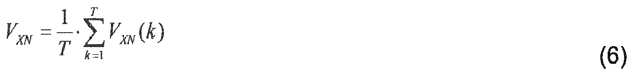
where T is the total number of counts/measurement samples per PWM cycle or per control interval (e.g., 5000 counts per PWM cycle and per control interval in a single control mode or 2500 counts per control mode in a double control mode(assuming a frequency of 5kHz and a sampling rate of 25mHz (e.g.,40ns)). - Returning to the DSP based method in
FIG. 7 , at S752, thesystem processor 120 determines a terminal voltage vector space using the present phase voltages VXN. Theprocessor 120 determines the terminal voltage vector space based on:
Theprocessor 120 splits the real and imaginary parts of the space vector Vs , in order to calculate the magnitude of the space vector Vs , based on:

By calculating the magnitude of the space vector Vs , theprocessor 120 determines the line-to-neutral terminal voltage peak (S753), which is the estimated terminal voltage, based on:
- At S755, the
system processor 120 may filter the estimated terminal voltage. Thesystem processor 120 may filter the estimated terminal voltage because the estimated terminal voltage may include undesired oscillations. Therefore, in order to provide a smoother control feedback signal, a filtering may be performed to eliminate the undesired oscillations. In one example embodiment, the filtering may be based on low-pass filtering of the estimated terminal voltage. In an example embodiment, the low-pass filtering may constitute calculating a moving average of the estimated terminal voltage. - At S756, the
system processor 120, via the threshold calculation module 127 (the threshold calculator 646), may determine a line-to-neutral peak voltage threshold (terminal voltage threshold) by:
- The square root of three is used to limit the terminal voltage to the linear region of the space vector pulse width modulation scheme. The DC bus voltage Vdc is a dynamic value and the terminal voltage will therefore also be a dynamic value dependent upon the DC bus voltage Vdc.
- Then there are two gains (terminal voltage limit gain motoring mode & terminal voltage limit gain braking mode), and depending on the operating mode, the processor selects the corresponding gain to be multiplied by the terminal voltage threshold. The gains are selected to limit the terminal voltage from a maximum value of Vterm_max down to a lower value. The value is can be different for different applications where a user may want to limit voltage to 460V, or perhaps to 440V.
- The
system processor 120 adjusts the terminal voltage threshold by a gain to further reduce maximum output voltage during motor and/or braking operating conditions (allowing a user to reduce the terminal voltage threshold to a select value) by:

- The gains may be selected by the
processor 120 in accordance with a selected maximum voltage. - The
system processor 120 may determine if the moving average filtered estimated terminal voltage is different than the actual machine terminal voltage. If so, the estimated terminal voltage can be modified by adding offset parameters to the estimated terminal voltage value. - To determine the difference, the
system processor 120 compares the estimated voltage to the actual measured (power analyzer or oscilloscope) terminal voltage. This comparison is done in an algorithm development phase to obtain offset parameters. Once the offsets have been determined, the actual voltage does not need to be measured. - The
system processor 120 determines the modified estimated terminal voltage for the motoring and braking modes by:

- The offset parameters Terminal Voltage Offset_Motoring Mode and Terminal Voltage Offset_Braking Mode may be determined by empirical data. For example, to select the offset parameter values, the
system processor 120 may disable a terminal voltage compensation enable parameter to prevent feedback control. By doing this, the estimated terminal voltage will still be calculated even though the closed loop control is disabled. Thesystem processor 120 compares the estimated terminal voltage values against the power analyzer actual machine terminal voltage values for motoring and braking conditions. Thesystem processor 120 adjusts the offset parameters Terminal Voltage Offset_Motoring Mode and Terminal Voltage Offset_Braking Mode accordingly for motoring and braking operations such that the estimated terminal voltage and the actual measured terminal voltage are equal and/or close to equal to each other. - At S757, the
system processor 120, via the terminalvoltage feedback module 108, shown inFIGS. 1A and 6, determines a terminal voltage feedback. Thesystem processor 120 may determine the terminal voltage feedback by determining a difference between a filtered estimated terminal voltage (after determining whether any offsets are to be applied) and the terminal voltage threshold (after determining whether the terminal voltage threshold is to be adjusted by a gain). In an example embodiment, the offsets and gains are always applied to the terminal voltage threshold and estimated terminal voltage. - If the filtered estimated terminal voltage exceeds the terminal voltage threshold, the
processor 120, via thecurrent adjustment module 107 and using the difference as a feedback parameter, may adjust the d-axis current command by decreasing the d-axis current command (S758). If the d-axis current needs to be modified it will change from a negative value (e.g., -110A) to a negative value having a magnitude is greater than the initial d-axis current command (e.g., -150A). - However, if the filtered estimated terminal voltage is lower than the terminal voltage threshold, the
processor 120 makes no adjustment in the d-axis current command (S759). At S760, theprocessor 120 adjusts the q-axis current command based on the adjustment of the d-axis current command so as to keep the total current magnitude constant. Therefore, if no adjustment is made to the d-axis current command at S759, then no subsequent adjustment to q-axis current command is made at S760, either. - The loop feedback described with reference to steps S757-S760 may be performed by a proportional integral (PI) controller in the
system processor 120. -
FIG. 8 illustrates adjustments to the d/q-axis current magnitudes and the corresponding angle such that the total current magnitude is kept constant, according to an example embodiment. Keeping the totalcurrent magnitude 880 the same (by adjusting the d-axiscurrent command 882 and q-axis current command 883) while changing thegamma angle 881 may enable a better control of the machine terminal voltage and avoiding excessive heating in motor windings on theinverter circuit 188. - Referring to
FIGS. 1 and 6, in one example embodiment, thecurrent adjustment module 107 may be executed by thesystem processor 120 in order to determine the d/q-axis current adjustment command and the gamma angle (designated as id adjustment command, iq adjustment command and Gamma angle adjustment in FIG. 6). - The adjustments to the d/q-axis current commands such that the total current magnitude is kept constant may be based on the following calculations:

where Is 880 ofFIG. 8 is the total current magnitude. The adjustment to the d-axiscurrent command 882 may be determined based on:
- Therefore, given (1) and (2), the adjustment to the q-axis
current command 883 may be determined based on:
- Further details regarding how the
processor 120 may determine the error as well as the adjustments to the d/q-axis current command are described in another patent application by the inventors (U.S. Pub. 2012/0217923 ), incorporated herein by reference, in its entirety. - The torque accuracy of a lookup table based control scheme is normally affected by the machine parameters variation and abnormal operating conditions such as inductances and flux linkage produced by a permanent magnet.
- Machine steel characteristics variation from different suppliers can cause different saturation behavior along d/q-axis and accordingly vary inductances Ld /Lq . These machine parameter variations can change the generated torque for a selected current operating point.
- By understanding that each machine has different characteristics and different behavior on parameter variation, it becomes difficult to achieve accurate torque production by using lookup table only based method.
- To increase the robustness to these uncertainties and maintain high accuracy torque production, the inventors have discovered a torque estimation scheme and a torque compensator. The torque observer scheme estimates an instantaneous shaft output torque. And a close-loop torque compensation scheme adjusts the current command based on the difference between the raw torque command and the estimated torque, such that the generated shaft torque can still follow the raw reference torque under machine parameter variation and different operating conditions.
- At least one example embodiment discloses a method of estimating shaft torque of an alternating current machine. The method includes determining phase current command values, estimating terminal voltage values based on actual phase current values and based on at least one of a duty cycle and a dead time ratio of the machine, transforming the terminal voltage values to derive direct and quadrature voltage representations consistent with the current command values, determining a terminal power of one or more terminals of the machine, the terminal power directly based on the direct and quadrature voltage representations of the machine and the current command values and determining an estimated shaft torque of the machine based on the terminal power in accordance with at least one efficiency value based on machine parameters from a characterization of the machine.
- In an example embodiment, the method further includes adjusting a torque command applied to the machine such that the estimated shaft torque substantially equals a torque command for a sampling interval.
- In an example embodiment, the efficiency value varies with at least one of the torque command and a voltage over speed ratio.
- In an example embodiment, the adjusting the torque command includes determining an error between the torque command and the estimated shaft torque, generating a saturated torque value based on the error and generating the adjusted torque command based on the saturated torque value.
- In an example embodiment, the adjusting the torque command includes generating the adjusted torque command based on a proportional integral (PI) function.
- In an example embodiment, the method further includes determining an operating mode, the operating mode being one of a braking mode and a motoring mode and obtaining an efficiency table associated with the operating mode, the efficiency table including efficiency values corresponding to torque command percentages and voltage-speed ratios, respectively, the efficiency table being stored in a storage device and the efficiency table including the at least one efficiency value.
- In an example embodiment, the method further includes receiving an input torque command percentage and an input voltage-speed ratio and determining an estimated shaft power based on the terminal power and the efficiency value corresponding to the input torque command percentage and the input voltage-speed ratio.
- In an example embodiment, the determining the estimated shaft torque includes determining a shaft torque based on the estimated shaft power and speed of the shaft and determining the estimated shaft torque by filtering the shaft torque.
- At least one example embodiment discloses a method of estimating shaft torque of an alternating current machine. The method includes measuring phase currents associated with one or more stator windings of the machine, estimating terminal voltage values based on the measured phase currents representations of the machine and based on at least one of a duty cycle and a dead time ratio of the machine, transforming the terminal voltage values to derive direct and quadrature voltage representations consistent with the measured phase currents, determining a terminal power of one or more terminals of the machine, the terminal power directly based on one of the estimated terminal voltage values and direct and quadrature voltage representations of the machine and current command values and determining an estimated shaft torque of the machine based on the terminal power in accordance with at least one efficiency value based on machine parameters from a characterization of the machine.
- In an example embodiment, the method further includes adjusting a torque command applied to the machine such that the estimated shaft torque substantially equals a torque command for a sampling interval.
- In an example embodiment, the efficiency value varies with at least one of the torque command and a voltage over speed ratio.
- In an example embodiment, the adjusting the torque command includes determining an error between the torque command and the estimated shaft torque, generating a saturated torque value based on the error and generating the adjusted torque command based on the saturated torque value.
- In an example embodiment, the adjusting the torque command includes generating the adjusted torque command based on a proportional integral (PI) function.
- In an example embodiment, the method further includes determining an operating mode, the operating mode being one of a braking mode and a motoring mode and obtaining an efficiency table associated with the operating mode, the efficiency table including efficiency values corresponding to torque command percentages and voltage-speed ratios, respectively, the efficiency table being stored in a storage device and the efficiency table including the at least one efficiency value.
- In an example embodiment, the method further includes receiving an input torque command percentage and an input voltage-speed ratio and determining an estimated shaft power based on the terminal power and the efficiency value corresponding to the input torque command percentage and the input voltage-speed ratio.
- In an example embodiment, the determining the estimated shaft torque includes determining a shaft torque based on the estimated shaft power and speed of the shaft and determining the estimated shaft torque by filtering the shaft torque. At least one example embodiment discloses a system including a processor configured to determine phase current command values associated with an alternating current machine, estimate terminal voltage values based on actual phase current values and based on at least one of a duty cycle and a dead time ratio of the alternating current machine, transform the terminal voltage values to derive direct and quadrature voltage representations consistent with the current command values, determine a terminal power of one or more terminals of the machine, the terminal power directly based on the direct and quadrature voltage representations of the machine and the current command values and determine an estimated shaft torque of the machine based on the terminal power in accordance with at least one efficiency value based on machine parameters from a characterization of the machine.
- In an example embodiment, the processor is configured to adjust a torque command applied to the machine such that the estimated shaft torque substantially equals a torque command for a sampling interval.
- In an example embodiment, the efficiency value varies with at least one of the torque command and a voltage over speed ratio.
- In an example embodiment, the processor is configured to determine an error between the torque command and the estimated shaft torque, generate a saturated torque value based on the error and generate the adjusted torque command based on the saturated torque value.
- In an example embodiment, the processor is configured to generate the adjusted torque command based on a proportional integral (PI) function.
- In an example embodiment, the processor is configured to determine an operating mode, the operating mode being one of a braking mode and a motoring mode and obtain an efficiency table associated with the operating mode, the efficiency table including efficiency values corresponding to torque command percentages and voltage-speed ratios, respectively, the efficiency table being stored in a storage device and the efficiency table including the at least one efficiency value.
- In an example embodiment, the processor is configured to receive an input torque command percentage and an input voltage-speed ratio and determine an estimated shaft power based on the terminal power and the efficiency value corresponding to the input torque command percentage and the input voltage-speed ratio.
- In an example embodiment, the processor is configured to determine a shaft torque based on the estimated shaft power and speed of the shaft and determine the estimated shaft torque by filtering the shaft torque.
- At least one example embodiment discloses a system including a processor configured to measure phase currents associated with one or more stator windings of an alternating current machine, estimate terminal voltage values based on the measured phase currents representations of the machine and based on at least one of a duty cycle and a dead time ratio of the machine, transform the terminal voltage values to derive direct and quadrature voltage representations consistent with the measured phase currents, determine a terminal power of one or more terminals of the machine, the terminal power directly based on one of the estimated terminal voltage values and direct and quadrature voltage representations of the machine and current command values and determine an estimated shaft torque of the machine based on the terminal power in accordance with at least one efficiency value based on machine parameters from a characterization of the machine.
- In an example embodiment, the processor is configured to adjust a torque command applied to the machine such that the estimated shaft torque substantially equals a torque command for a sampling interval.
- In an example embodiment, the efficiency value varies with at least one of the torque command and a voltage over speed ratio.
- In an example embodiment, the processor is configured to determine an error between the torque command and the estimated shaft torque, generate a saturated torque value based on the error and generate the adjusted torque command based on the saturated torque value.
- In an example embodiment, the processor is configured to generate the adjusted torque command based on a proportional integral (PI) function.
- In an example embodiment, the processor is configured to determine an operating mode, the operating mode being one of a braking mode and a motoring mode and obtain an efficiency table associated with the operating mode, the efficiency table including efficiency values corresponding to torque command percentages and voltage-speed ratios, respectively, the efficiency table being stored in a storage device and the efficiency table including the at least one efficiency value.
- In an example embodiment, the processor is configured to receive an input torque command percentage and an input voltage-speed ratio and determine an estimated shaft power based on the terminal power and the efficiency value corresponding to the input torque command percentage and the input voltage-speed ratio.
- In an example embodiment, the processor is configured to determine a shaft torque based on the estimated shaft power and speed of the shaft and determine the estimated shaft torque by filtering the shaft torque.
- Referring back to
FIG. 3 , thetorque estimation module 129 generates estimated torque data Test based on the inverter phase voltages VAN, VBN and VCN, generated from the machine terminal voltage estimation described above. - As will be described in greater detail below, the
torque estimation module 129 estimates terminal power directly based on terminal voltage and current commands. An efficiency converts the terminal power into shaft power. The current commands are used instead of actual current to reduce oscillation in estimated power. Thetorque estimation module 129 estimates machine shaft torque based on the estimated power, measured speed and operating point efficiency information. The operating point efficiency information is stored in a lookup table, which is obtained during a motor characterization stage. - During motor characterization, multiple current commands are used at different speed points, which generates MTPA (maximum torque per amp) and MTPV (maximum torque per volt) curves. Many items are recorded such as phase current, phase voltage, torque, speed, etc. Efficiency data is generated by recording machine input power (terminal power) and also shaft power. By dividing shaft power by input power for each characterized operational point, an efficiency lookup table is generated. Then the inputs to the lookup table are the torque command percentage and voltage/speed ratio. The output will be an efficiency value.
- Generally, motor characterization is a procedure used to determine d-axis and q-axis commands for a specific speed and torque command. The procedure is repeated at multiple torque commands and multiple speeds. Any know motor characterization procedure may be used.
- The
torque estimation module 129 does not need to use machine parameters information. - The
torque estimation module 129 includes the rotor position θvcalculation module 310 which determines the rotor position θv for a Park transformation on the phase voltages VAN, VBN and VCN. The rotorposition calculation module 310 determines the rotor position θv based on a rotor position used for a Park transformation on phase currents θp or an extrapolated rotor position used for an inverse Park transformation in SVPWM θe. - The rotor position θp is the actual rotor position value (from a resolver) at the same instant the phase currents are sampled. θe is calculated by the processor from θp, deadtime, PWM period, and speed.
-
FIGS. 9A-9C illustrate different examples of calculating the rotor position θv. -
FIG. 9A illustrates an example embodiment of determining the rotor position θv using double control DSP based terminal voltage estimation. -
FIG. 9A illustrates four control cycles, which are equivalent to two PWM switching cycles using double control. Using the kth control cycle as an example, thesystem processor 120 executes numerous tasks. - When the phase current information at the kth cycle, i.e., iabc [k] is ready, the
system processor 120 will get this current information. With the rotor position at this time instant after compensation, i.e., the rotor position θ P [k], Park transformation on the phase currents is performed to get the actual current idq [k]. - The
current regulation controller 111 generates voltage reference

- The
PWM module 112 generates three phase duty ratios dabc [k] based on
- For double control, the relationship between θ e [k] and θ P [k] in the PWM_Theta_Extropolation_Down Mode, can be expressed as:

where Ts stands for the period of control iteration (denote period of PWM switching cycle as T s,sw, for single control T s = T s,sw, while for double control T s = T s,sw/2). - As should be understood Up Mode and Down Mode refer to the positive and negative slopes, respectively, of the PWM waveform.
- For the PWM_Theta_Extropolation_Up Mode, the equation for position extrapolation is different, and can be expressed as:

- The machine terminal voltage estimation scheme, as described above, is performed by the
system processor 120 at this step k, which uses information such as duty ratio information dabc [k - 1], phase current information iabc [k] and DC bus voltage Vdc [k]. The estimated terminal phase voltage is VabcN [k]. - Referring to
FIG. 9A , the time instant of the rotor position θ v [k] is synchronized with the averaging time instant of VabcN [k]. Therefore, thesystem processor 120 calculates the rotor position θ v [k] as:
or determined by:
- As should be understood, k stands for index of the control iteration (cycle). The k index after variable indicates the corresponding variable is used at that control iteration. For example, the rotor position θP[k] means the rotor position θ P is used in the kth control iteration. Another example, the rotor position θ e [k] means the rotor position θ e is used in the kth control iteration. Although the rotor position θ e [k] is extrapolated position and it locates in the next control cycle, i.e., k+1th, it is calculated and used the kth control iteration.
-
FIG. 9B illustrates an example embodiment of determining the rotor position θv using double control FPGA based terminal voltage estimation. The time instant of the rotor position θ v [k] is still synchronized with the averaging time instant of VABCN [k]. - Considering the time period used for terminal voltage estimation by FPGA method, the
system processor 120 calculates the rotor position θ v [k] as:
or:
- The 23.2 us is the sum of the hardware delay and the FPGA filter delay. The filter delay is determined by the order of the filters. Therefore, the value for the sum of the delays could be varying due to different filter structure and orders.
- The bottom waveform illustrates when the DSP interrupt service routine (ISR) fires, and the maximum amount of time the DSP has to execute the entire motor control algorithm.
-
FIG. 9C illustrates an example embodiment of determining the rotor position θv using single control FPGA based terminal voltage estimation. - In the kth control cycle, the current command

system processor 120 calculates the present phase voltages VABCN [k] in the k-1th cycle, and uses them the kth control cycle. The rotor position used for voltage Park Transformation at the kth cycle is as the rotor position θ v [k], which is located in the mid-point of one Ts . The relationship between the rotor positions θ v [k] and θ P [k] can be expressed as:
or:
- Referring back to
FIG. 3 , thePark transformation module 315 obtains the rotor position θv from the rotorposition calculation module 310. ThePark transformation module 315 performs a Park transformation on the present phase voltages VABCN to generate rotating reference frame dq-axis voltages Vdq. - As should be understood, reference frame refers to a coordinate system used to represent and measure properties such as position (e.g., angular rotational position), velocity, torque, electrical parameters, and orientation of the rotor of the motor, the stator of the motor, or both. In a rotating reference frame, the instantaneous stator currents of a multi-phase motor can be expressed as a single complex stator current vector in a Cartesian coordinate system. If a Park transform or a similar transform is applied to the complex stator current vector, the reference frame has direct axis (d-axis) and quadrature axis (q-axis) components that rotate with rotor flux position (e.g., local maximum in magnetic field). For a motor with permanent magnets attached to the rotor the rotor flux position does not change with respect to the rotor, as opposed to where electromagnets are used in certain rotors.
- The
system processor 120 obtains voltage components V αβ in a two-phase stationary reference frame. In a stationary reference frame, the position (e.g., angular rotational position), rotational velocity, torque, electrical parameters and orientation of the rotor, the stator, or both are observed from a stationary observer's point of view. A stationary reference frame may refer to the case where the reference frame is aligned with the stator of the motor, or where the d-axis and the q-axis do not rotate with the rotor. For the rotor or stator, a stationary reference frame is mutually exclusive to a rotating reference frame. - The voltage components V αβ are equivalent to the voltage components Vs_real and Vs_imaginary, respectively, which are determined in the machine power estimation described above, as:


Thesystem processor 120 performs the Park transformation as:
- To further reduce the oscillation in the calculated Vdq, a moving-average may be implemented. The window length for moving average may vary according to the execution rates of the Park transform on voltage and moving average functions. For example, a 10 ms window length may be used. If the PWM frequency is 6000 Hz, 60 steps moving average is equivalent to 60/6 = 10 ms.
- The terminal
power estimation module 320 obtains the rotating reference frame dq-axis voltages Vdq from thePark transformation module 315. The terminalpower estimation module 320 generates an estimated terminal power Pest based on the voltages Vdq and the final current commands id*, iq*, which may be the current commands iq_cmd, id_cmd or adjusted values thereof if the estimated terminal voltage is above the terminal voltage threshold. - The terminal
power estimation module 320 is based on the basic relationship among machine terminal power, shaft torque, voltage and current. From mechanical standpoint, the terminal input power can be expressed as:
where ΔPlosses is the total power losses, which includes copper loss, core loss, friction & windage, etc., and ω shaft is the shaft speed, Tshaft is the shaft torque. From electrical standpoint, the terminal input power can be expressed as:
- Since the actual dq-axis current information may have large oscillations around respective reference values, the final dq-axis current commands id*, iq* are used to be used in power estimation. Therefore, the
system processor 120 calculates the estimated terminal power Pest as:
- The shaft
torque estimation module 330 obtains the estimated terminal power Pest from the terminalpower estimation module 320. The shafttorque estimation module 330 generates an estimated torque based on the estimated terminal power Pest, an interpolated efficiency η and shaft speed ωshaft. The shaft speed ωshaft may be obtained using any known method. - In an IPM characterization procedure, machine efficiency data corresponding to each torque command percentage and voltage-speed ratio combination are available. Similar to the dq-axis current lookup table, an efficiency lookup table is also created from characterization, which also uses ratio and torque command percentage as inputs. Considering the efficiency table and current lookup tables have the same inputs, efficiency lookup table is connected in parallel with the id and iq lookup tables (e.g., 109) to share the same inputs. In the case of separate motoring and braking characterization, there will be two different efficiency lookup tables for motoring and braking modes.
- The
efficiency extraction module 325 includes efficiency lookup tables (stored in the data storage device 260) for motoring and braking modes, respectively. Based on the torque command percentage, ratio and mode, theefficiency extraction module 325 utilizes the lookup table associated with the mode and produces the interpolated efficiency η. - For motoring mode,

- While for braking mode,

- The shaft torque estimation module estimates the torque Test as follows:
- Since the operating point effeciency data has been collected during the IPM characterization stage, the interpolated effciency η under any speed and loading condition can be utilized by the shaft
torque estimation module 330 to handle the power losses as:
- To further filter out noise in the estimated torque, a second order low-pass filter may be used by the shaft
torque estimation module 330. And the final expression for estimated torque by the shafttorque estimation module 330 is:
where A is the DC gain of the second order low pass filter. - The
torque compensation module 131 uses an error between estimated shaft torque and raw torque command to adjust raw torque command. Thetorque compensation module 131 reduces the error between estimated torque and raw torque command. Since only the torque command has been modified, the current command trajectory is still determined by the dq-axis current lookup table, which forces the current commands close to the optimal efficiency. - The
torque compensation module 131 is configured to generate the final torque command data Tcmd_final based on the estimated torque data Test from the shafttorque estimation module 330. Thetorque compensation module 131 may be slewing based or PI based. -
FIG. 10 illustrates a slewing based torque compensation scheme according to an example embodiment. - As shown in
FIG. 10 , atorque compensation module 131A determines a difference between the estimated torque data Test and the torque command Tcmd, which is identified as Terr. Thetorque compensation module 131A passes the difference through alimiter 1030. The limits of thelimiter 1030 are determined on a system level basis and based on empirical data. They are determined by the processor based on the machine which theinverter circuit 188 is electrically connected to. For example, if a machine has a very large rated torque the error limiter will be larger than if a machine has a much smaller rated torque. - The
limiter 1030 outputs a saturated difference Terr_sat to adetermination unit 1050. Thetorque compensation module 131A then determines whether the saturated difference Terr_sat is greater than an error margin. Similar to the limits of the limiter, the error margin is determined on a system level basis and based on empirical data. If the saturated difference Terr_sat is less than or equal to an error margin, thedetermination unit 1050 determines that the final torque command Tcmd_final for a kth cycle is the final torque command for the previous k-1th cycle. If the saturated difference Terr_sat is greater than an error margin, thedetermination unit 1050 determines that the final torque command Tcmd_adj for a kth cycle is the final torque command for the previous k-1th cycle plus the saturated difference Terr_sat. -
FIG. 11 illustrates a PI based torque compensation scheme according to an example embodiment. Atorque compensation module 131B includes aPI regulator 1105. - The
PI regulator 1105 generates an adjustment to the raw torque command Tcmd. This adjustment is added to the raw torque command Tcmd to form a compensated torque command Tcmd_compensate. - The
PI regulator 1105 obtains an error between the raw torque command Tcmd and the estimated torque Test. ThePI regulator 1105 obtains PI gains from a table 1110. The PI gains are tuned online. The PI gains are tuned in laboratory testing. The gains are set by determining values for rise time, steady state error, and other PI controller system design characteristics. Once the gains are obtained they are stored in thedata storage device 260. - The
PI regulator 1105 also obtains limits from a table 1115 and an integrator hold signal from anintegrator generator 1120. The limits from the table 1115 include both integrator and PI sum limits. The limits are set to be a percentage of the raw torque command. For example, the limits can be 10% of the raw torque command, so for a 100Nm raw torque command the integrator and sum limits are 10Nm. This will give a maximum adjusted torque command of 10Nm and a maximum final torque command of 110Nm. - The
PI regulator 1105 is also configured to obtain a reset signal. The reset signal may be generated by an OR gate whenever a PI rest enable signal, a switch control disable signal or torque compensation disable signal is received. Upon a reset the integrator value is reset. - The
PI regulator 1105 outputs a torque command adjustment term, ΔT, based on the error, PI gains and limits. - An
adder 1130 adds the raw torque command Tcmd and the torque command adjustment Tcmd_adj. The output of theadder 1130 is input to atorque command limiter 1135 which produces the adjusted compensated torque command Tcmd_compensate. Thetorque command limiter 1135 prevents the sum of raw torque command Tcmd and the torque command adjustment Tcmd_adj from exceeding a torque limit. -
FIG. 12 illustrates a method of generating the torque upper/lower limits for thetorque command limiter 1135, according to an example embodiment. - Based on speed-torque curve, customer rated torque Cust_Rated_Torq_Nm is obtained. Based on a ratio-torque curve, the base torque Base_Torq is obtained. From the motor characterization data, base torque values are respectively associated with discrete speed points with a nominal dc bus voltage level. During the IPM motor characterization procedure, each characterized rotor shaft speed has a maximum output torque which is defined as the base torque at that speed. Thus, the base torque may also be referred to a peak torque.
- The minima of customer rated torque and base torque is used as a rated torque Rated_Torq_Nm. And then the torque upper and lower limits are determined by the products of rated torque and derating torque percentage (Torq_Upper/Lower_Limit_pct_out).
- The upper and lower limits are then determined by the product of the rated torque Rated_Torq_Nm and the upper/lower derating torque percentage. These percentages range from 0% (fully derated) to 100% (no derate). There a several ways the upper/lower derating torque percentages are calculated. In an example embodiment, there can be a derating for high machine temperature, high inverter temperature, DC bus voltage, machine speed, hardware limits, etc. The derating which is the most severe (lowest percentage) is used as the final derating percentage value.
- The rated torque is limited to a peak characterized torque and also hardware toque command limit.
- Referring back to
FIG. 11 , aselector 1140 selects one of the raw torque command Tcmd and the compensated torque command Tcmd_compensate as the final torque command Tcmd_final. - The
selector 1140 receives a Torq_Comp_Enable flag to determine which torque command, raw torque command Tcmd or compensated torque Tcmd_compensate, should be used as the actual final torque command Tcmd_final. - There are several examples to determine the value of Torq_Comp_Enable, i.e., whether to enable the torque compensator or not. For testing purposes, a manually changed global flag may be used. In another example embodiment the Torq_Comp_Enable flag may be based on speed. For example, the system processor may enable the torque compensator the speed exceeds 1000 RPM. This speed dependent enable feature can be implemented by using hysteresis or relay.
-
FIG. 13 illustrates a method of torque estimation and compensation according to an example embodiment. The method ofFIG. 13 may be performed by theprocessor 120 and, more specifically, the machine terminalvoltage estimation module 127, thetorque estimation module 129 and thetorque compensation module 131. - At S1305, the
processor 120 determines phase currents (ia, ib and ic). At S1310, theprocessor 120 estimates the terminal voltage of the machine. For example, the terminal voltage may be estimated using the method shown inFIG. 7 . The processor then transforms the estimated terminal voltage at S1315. For example, thePark transformation module 315 obtains the rotor position θv from the rotorposition calculation module 310. ThePark transformation module 315 performs a Park transformation on the real and imaginary portions of the estimated terminal voltage to generate rotating reference frame dq-axis voltages Vdq. The processor then determines a terminal power at S1320. For example, the terminalpower estimation module 320 obtains the rotating reference frame dq-axis voltages Vdq from thePark transformation module 315. The terminalpower estimation module 320 generates an estimated terminal power Pest based on the voltages Vdq and the final current commands id*, iq*, which may be the current commands iq_cmd, id_cmd or adjusted values thereof if the estimated terminal voltage is above the terminal voltage threshold. - At S1325, the processor determines an estimated shaft torque. The estimated shaft torque may be estimated the interpolated effciency η under any speed and loading condition can be utilized by the shaft
torque estimation module 330 to handle the power losses as:
- To further filter out noise in the estimated torque, a second order low-pass filter may be used by the shaft
torque estimation module 330. And the final expression for estimated torque by the shafttorque estimation module 330 is:
- Example embodiments being thus described, it will be obvious that the same may be varied in many ways. Such variations are not to be regarded as a departure from the spirit and scope of example embodiments, and all such modifications as would be obvious to one skilled in the art are intended to be included within the scope of the claims.
Claims (16)
- A method of estimating shaft torque of an alternating current machine, the method comprising:determining phase current command values;estimating terminal voltage values based on actual phase current values and based on at least one of a duty cycle and a dead time ratio of the machine;transforming the terminal voltage values to derive direct and quadrature voltage representations consistent with the current command values;determining a terminal power of one or more terminals of the machine, the terminal power directly based on the direct and quadrature voltage representations of the machine and the current command values; anddetermining an estimated shaft torque of the machine based on the terminal power in accordance with at least one efficiency value based on machine parameters from a characterization of the machine.
- The method according to claim 1, further comprising:adjusting a torque command applied to the machine such that the estimated shaft torque substantially equals a torque command for a sampling interval.
- The method according to claim 2, wherein the efficiency value varies with at least one of the torque command and a voltage over speed ratio.
- The method of claims 2 or 3, wherein the adjusting the torque command includes,
determining an error between the torque command and the estimated shaft torque,
generating a saturated torque value based on the error, and
generating the adjusted torque command based on the saturated torque value. - The method of claims 2 or 3, wherein the adjusting the torque command includes,
generating the adjusted torque command based on a proportional integral (PI) function. - The method of any of claims 1 to 5, further comprising:determining an operating mode, the operating mode being one of a braking mode and a motoring mode; andobtaining an efficiency table associated with the operating mode, the efficiency table including efficiency values corresponding to torque command percentages and voltage-speed ratios, respectively, the efficiency table being stored in a storage device and the efficiency table including the at least one efficiency value.
- The method of claim 6, further comprising:receiving an input torque command percentage and an input voltage-speed ratio; anddetermining an estimated shaft power based on the terminal power and the efficiency value corresponding to the input torque command percentage and the input voltage-speed ratio.
- The method of claim 7, wherein the determining the estimated shaft torque includes,
determining a shaft torque based on the estimated shaft power and speed of the shaft, and
determining the estimated shaft torque by filtering the shaft torque. - A system comprising:a processor configured to,
determine phase current command values associated with an alternating current machine;
estimate terminal voltage values based on actual phase current values and based on at least one of a duty cycle and a dead time ratio of the alternating current machine;
transform the terminal voltage values to derive direct and quadrature voltage representations consistent with the current command values;
determine a terminal power of one or more terminals of the machine, the terminal power directly based on the direct and quadrature voltage representations of the machine and the current command values; and
determine an estimated shaft torque of the machine based on the terminal power in accordance with at least one efficiency value based on machine parameters from a characterization of the machine. - The system according to claim 9, wherein the processor is configured to,
adjust a torque command applied to the machine such that the estimated shaft torque substantially equals a torque command for a sampling interval. - The system according to claim 10, wherein the efficiency value varies with at least one of the torque command and a voltage over speed ratio.
- The system of claim 10 or 11, wherein the processor is configured to,
determine an error between the torque command and the estimated shaft torque,
generate a saturated torque value based on the error, and
generate the adjusted torque command based on the saturated torque value. - The system of claim 10, wherein the processor is configured to,
generate the adjusted torque command based on a proportional integral (PI) function. - The system of any of claims 9 to 13, wherein the processor is configured to,
determine an operating mode, the operating mode being one of a braking mode and a motoring mode, and
obtain an efficiency table associated with the operating mode, the efficiency table including efficiency values corresponding to torque command percentages and voltage-speed ratios, respectively, the efficiency table being stored in a storage device and the efficiency table including the at least one efficiency value. - The system of claim 14, wherein the processor is configured to,
receive an input torque command percentage and an input voltage-speed ratio, and
determine an estimated shaft power based on the terminal power and the efficiency value corresponding to the input torque command percentage and the input voltage-speed ratio. - The system of claim 15, wherein the processor is configured to,
determine a shaft torque based on the estimated shaft power and speed of the shaft, and
determine the estimated shaft torque by filtering the shaft torque.
Applications Claiming Priority (1)
| Application Number | Priority Date | Filing Date | Title |
|---|---|---|---|
| US14/141,709 US9442029B2 (en) | 2013-12-27 | 2013-12-27 | Methods of torque estimation and compensation and systems thereof |
Publications (2)
| Publication Number | Publication Date |
|---|---|
| EP2889999A1 true EP2889999A1 (en) | 2015-07-01 |
| EP2889999B1 EP2889999B1 (en) | 2017-09-06 |
Family
ID=52015877
Family Applications (1)
| Application Number | Title | Priority Date | Filing Date |
|---|---|---|---|
| EP14195712.6A Active EP2889999B1 (en) | 2013-12-27 | 2014-12-01 | Methods of torque estimation and compensation and systems thereof |
Country Status (4)
| Country | Link |
|---|---|
| US (1) | US9442029B2 (en) |
| EP (1) | EP2889999B1 (en) |
| CN (1) | CN104753423B (en) |
| BR (1) | BR102014032512B1 (en) |
Cited By (6)
| Publication number | Priority date | Publication date | Assignee | Title |
|---|---|---|---|---|
| CN109818542A (en) * | 2017-11-21 | 2019-05-28 | 现代自动车株式会社 | The rotary transformer offset correction device and method of environmentally friendly vehicle |
| WO2019118955A1 (en) * | 2017-12-17 | 2019-06-20 | Microchip Technology Incorporated | Closed loop torque compensation for compressor applications |
| RU2706416C1 (en) * | 2018-12-03 | 2019-11-19 | Федеральное государственное бюджетное образовательное учреждение высшего образования "Казанский национальный исследовательский технический университет им. А.Н. Туполева-КАИ" (КНИТУ-КАИ) | Valve electric drive |
| CN112564564A (en) * | 2020-11-27 | 2021-03-26 | 东风汽车集团有限公司 | Motor torque closed-loop control method based on torque estimation |
| WO2021088626A1 (en) * | 2019-11-04 | 2021-05-14 | 广州新科佳都科技有限公司 | Servo control method and apparatus for door module, electronic device and storage medium |
| SE2251104A1 (en) * | 2022-09-23 | 2024-03-24 | Volvo Truck Corp | Vehicle retardation torque control |
Families Citing this family (21)
| Publication number | Priority date | Publication date | Assignee | Title |
|---|---|---|---|---|
| US9559630B2 (en) * | 2014-03-28 | 2017-01-31 | Deere & Company | System and method for controlling modulation of an inverter |
| US9768719B2 (en) * | 2015-09-18 | 2017-09-19 | Faraday&Future Inc. | Methods and apparatus for generating current commands for an interior permanent magnet (IPM) motor |
| JP6432698B2 (en) * | 2016-01-22 | 2018-12-05 | 東芝三菱電機産業システム株式会社 | Speed control device for electric motor |
| US9748882B1 (en) * | 2016-03-28 | 2017-08-29 | Amazon Technologies, Inc. | Integrated motor driver/controller with sensorless or sensored commutation |
| KR101897327B1 (en) * | 2016-04-25 | 2018-09-11 | 국방과학연구소 | Real-time off-set removal method of force measuring sensor |
| EP3476695B1 (en) * | 2016-08-24 | 2020-11-18 | NSK Ltd. | Electric power steering device |
| US10093184B2 (en) * | 2016-09-09 | 2018-10-09 | Ford Global Technologies, Llc | Direct current voltage clamping in a vehicle |
| JP2018087535A (en) * | 2016-11-29 | 2018-06-07 | 三菱重工サーマルシステムズ株式会社 | Rotational speed control device, rotary compressor system, control system and rotational speed control method |
| US10686393B2 (en) * | 2018-02-05 | 2020-06-16 | Zhongshan Broad-Ocean Motor Co., Ltd. | Method for correcting compensation item of permanent magnet synchronous motor (PMSM) |
| JP6936171B2 (en) * | 2018-02-28 | 2021-09-15 | サンデン・オートモーティブコンポーネント株式会社 | Motor control device |
| CN108494295B (en) * | 2018-03-13 | 2021-02-19 | 江西精骏电控技术有限公司 | Model-based nonlinear compensation and temperature compensation method for alternating current motor inverter |
| CN110962631B (en) * | 2018-12-29 | 2020-11-17 | 宁德时代新能源科技股份有限公司 | Battery heating system and control method thereof |
| CN109713950B (en) * | 2019-02-20 | 2020-07-31 | 浙江大学 | Suppression system and method for torque ripple of permanent magnet synchronous motor |
| CN110729941B (en) * | 2019-10-29 | 2021-04-02 | 中车永济电机有限公司 | Control method of built-in permanent magnet synchronous motor |
| CN110843550B (en) * | 2019-11-14 | 2021-06-18 | 深圳市福瑞电气有限公司 | Method for eliminating low-speed jitter of electric automobile |
| US11670995B2 (en) | 2020-01-31 | 2023-06-06 | Deere & Company | Method and apparatus for operating a dual rotor electrical machine |
| US11609137B2 (en) * | 2020-03-30 | 2023-03-21 | Rockwell Automation Technologies, Inc. | Estimating motor drive torque and velocity |
| DE102020109481A1 (en) * | 2020-04-06 | 2021-10-07 | Audi Aktiengesellschaft | Control unit, control circuit and motor vehicle |
| JP7449471B2 (en) * | 2020-06-08 | 2024-03-14 | 株式会社ジェイテクト | motor control device |
| CN113890443B (en) | 2020-06-17 | 2023-09-05 | 台达电子工业股份有限公司 | Motor rotor frequency estimation method |
| CN111797518B (en) * | 2020-06-23 | 2023-04-18 | 电子科技大学 | Load solving method under low-frequency torque compensation of compressor |
Citations (2)
| Publication number | Priority date | Publication date | Assignee | Title |
|---|---|---|---|---|
| EP1263125A2 (en) * | 2001-05-31 | 2002-12-04 | Toyota Jidosha Kabushiki Kaisha | Drive control apparatus and method of alternating current motor |
| US20120217923A1 (en) | 2011-02-28 | 2012-08-30 | Long Wu | System for Controlling a Motor |
Family Cites Families (4)
| Publication number | Priority date | Publication date | Assignee | Title |
|---|---|---|---|---|
| DE102009046583A1 (en) * | 2009-11-10 | 2011-05-12 | Robert Bosch Gmbh | Method for plausibilizing the torque of an electrical machine and machine controller for controlling an electrical machine and for carrying out the method |
| US8519662B2 (en) * | 2010-05-26 | 2013-08-27 | Rockwell Technologies, Inc. | Method and apparatus for controlling motor torque |
| CN201910764U (en) * | 2010-12-14 | 2011-07-27 | 长春工业大学 | Permanent magnet synchronous motor (PMSM) direct torque control system based on terminal sliding mode |
| US9071186B2 (en) | 2013-04-12 | 2015-06-30 | Deere & Company | Method and apparatus for controlling an alternating current machine |
-
2013
- 2013-12-27 US US14/141,709 patent/US9442029B2/en active Active
-
2014
- 2014-12-01 EP EP14195712.6A patent/EP2889999B1/en active Active
- 2014-12-23 BR BR102014032512-3A patent/BR102014032512B1/en active IP Right Grant
- 2014-12-29 CN CN201410836342.7A patent/CN104753423B/en active Active
Patent Citations (2)
| Publication number | Priority date | Publication date | Assignee | Title |
|---|---|---|---|---|
| EP1263125A2 (en) * | 2001-05-31 | 2002-12-04 | Toyota Jidosha Kabushiki Kaisha | Drive control apparatus and method of alternating current motor |
| US20120217923A1 (en) | 2011-02-28 | 2012-08-30 | Long Wu | System for Controlling a Motor |
Cited By (9)
| Publication number | Priority date | Publication date | Assignee | Title |
|---|---|---|---|---|
| CN109818542A (en) * | 2017-11-21 | 2019-05-28 | 现代自动车株式会社 | The rotary transformer offset correction device and method of environmentally friendly vehicle |
| CN109818542B (en) * | 2017-11-21 | 2023-08-22 | 现代自动车株式会社 | Resolver offset correction apparatus and method for environment-friendly vehicle |
| WO2019118955A1 (en) * | 2017-12-17 | 2019-06-20 | Microchip Technology Incorporated | Closed loop torque compensation for compressor applications |
| US11499537B2 (en) | 2017-12-17 | 2022-11-15 | Microchip Technology Incorporated | Closed loop torque compensation for compressor applications |
| RU2706416C1 (en) * | 2018-12-03 | 2019-11-19 | Федеральное государственное бюджетное образовательное учреждение высшего образования "Казанский национальный исследовательский технический университет им. А.Н. Туполева-КАИ" (КНИТУ-КАИ) | Valve electric drive |
| WO2021088626A1 (en) * | 2019-11-04 | 2021-05-14 | 广州新科佳都科技有限公司 | Servo control method and apparatus for door module, electronic device and storage medium |
| CN112564564A (en) * | 2020-11-27 | 2021-03-26 | 东风汽车集团有限公司 | Motor torque closed-loop control method based on torque estimation |
| CN112564564B (en) * | 2020-11-27 | 2022-11-18 | 东风汽车集团有限公司 | Motor torque closed-loop control method based on torque estimation |
| SE2251104A1 (en) * | 2022-09-23 | 2024-03-24 | Volvo Truck Corp | Vehicle retardation torque control |
Also Published As
| Publication number | Publication date |
|---|---|
| BR102014032512B1 (en) | 2021-01-19 |
| CN104753423A (en) | 2015-07-01 |
| BR102014032512A2 (en) | 2016-10-18 |
| CN104753423B (en) | 2019-03-05 |
| EP2889999B1 (en) | 2017-09-06 |
| US9442029B2 (en) | 2016-09-13 |
| US20150185095A1 (en) | 2015-07-02 |
Similar Documents
| Publication | Publication Date | Title |
|---|---|---|
| EP2889999B1 (en) | Methods of torque estimation and compensation and systems thereof | |
| US9270223B2 (en) | Methods of determining machine terminal voltage and systems thereof | |
| US9071186B2 (en) | Method and apparatus for controlling an alternating current machine | |
| US8744794B2 (en) | Method and apparatus for characterizing an interior permanent magnet machine | |
| EP3002872B1 (en) | Methods of estimating rotor magnet temperature and systems thereof | |
| US8853979B2 (en) | Method and system for calibrating rotor position offset of an electric motor | |
| US9559630B2 (en) | System and method for controlling modulation of an inverter | |
| US9735722B2 (en) | Methods of controlling a machine using a torque command limit derived from a current limit and systems thereof | |
| EP2681838B1 (en) | Interior permanent magnet machine systems | |
| EP3703245B1 (en) | Method and system for controlling a permanent magnet machine without a mechanical position sensor | |
| US20140225540A1 (en) | Control apparatus for ac motor | |
| US10763769B2 (en) | Controller for power convertor and motor driving system | |
| US10044310B2 (en) | Methods of auto tuning machine parameters and systems thereof | |
| Zhao et al. | Stability and dynamic performance improvement of a sensorless IPMSM drive via adaptive estimated-speed-assisted position prediction and current quality evaluation | |
| BR112015024832B1 (en) | CONTROL DEVICE, AND, METHOD FOR CONTROLLING AN AC MACHINE |
Legal Events
| Date | Code | Title | Description |
|---|---|---|---|
| PUAI | Public reference made under article 153(3) epc to a published international application that has entered the european phase |
Free format text: ORIGINAL CODE: 0009012 |
|
| 17P | Request for examination filed |
Effective date: 20141201 |
|
| AK | Designated contracting states |
Kind code of ref document: A1 Designated state(s): AL AT BE BG CH CY CZ DE DK EE ES FI FR GB GR HR HU IE IS IT LI LT LU LV MC MK MT NL NO PL PT RO RS SE SI SK SM TR |
|
| AX | Request for extension of the european patent |
Extension state: BA ME |
|
| R17P | Request for examination filed (corrected) |
Effective date: 20160104 |
|
| RBV | Designated contracting states (corrected) |
Designated state(s): AL AT BE BG CH CY CZ DE DK EE ES FI FR GB GR HR HU IE IS IT LI LT LU LV MC MK MT NL NO PL PT RO RS SE SI SK SM TR |
|
| GRAP | Despatch of communication of intention to grant a patent |
Free format text: ORIGINAL CODE: EPIDOSNIGR1 |
|
| RIC1 | Information provided on ipc code assigned before grant |
Ipc: H02P 21/14 20160101AFI20170301BHEP |
|
| INTG | Intention to grant announced |
Effective date: 20170328 |
|
| GRAS | Grant fee paid |
Free format text: ORIGINAL CODE: EPIDOSNIGR3 |
|
| GRAA | (expected) grant |
Free format text: ORIGINAL CODE: 0009210 |
|
| AK | Designated contracting states |
Kind code of ref document: B1 Designated state(s): AL AT BE BG CH CY CZ DE DK EE ES FI FR GB GR HR HU IE IS IT LI LT LU LV MC MK MT NL NO PL PT RO RS SE SI SK SM TR |
|
| REG | Reference to a national code |
Ref country code: GB Ref legal event code: FG4D |
|
| REG | Reference to a national code |
Ref country code: CH Ref legal event code: EP Ref country code: AT Ref legal event code: REF Ref document number: 926900 Country of ref document: AT Kind code of ref document: T Effective date: 20170915 |
|
| REG | Reference to a national code |
Ref country code: IE Ref legal event code: FG4D |
|
| REG | Reference to a national code |
Ref country code: DE Ref legal event code: R096 Ref document number: 602014014108 Country of ref document: DE |
|
| REG | Reference to a national code |
Ref country code: FR Ref legal event code: PLFP Year of fee payment: 4 |
|
| REG | Reference to a national code |
Ref country code: NL Ref legal event code: MP Effective date: 20170906 |
|
| REG | Reference to a national code |
Ref country code: LT Ref legal event code: MG4D |
|
| PG25 | Lapsed in a contracting state [announced via postgrant information from national office to epo] |
Ref country code: FI Free format text: LAPSE BECAUSE OF FAILURE TO SUBMIT A TRANSLATION OF THE DESCRIPTION OR TO PAY THE FEE WITHIN THE PRESCRIBED TIME-LIMIT Effective date: 20170906 Ref country code: LT Free format text: LAPSE BECAUSE OF FAILURE TO SUBMIT A TRANSLATION OF THE DESCRIPTION OR TO PAY THE FEE WITHIN THE PRESCRIBED TIME-LIMIT Effective date: 20170906 Ref country code: NO Free format text: LAPSE BECAUSE OF FAILURE TO SUBMIT A TRANSLATION OF THE DESCRIPTION OR TO PAY THE FEE WITHIN THE PRESCRIBED TIME-LIMIT Effective date: 20171206 Ref country code: SE Free format text: LAPSE BECAUSE OF FAILURE TO SUBMIT A TRANSLATION OF THE DESCRIPTION OR TO PAY THE FEE WITHIN THE PRESCRIBED TIME-LIMIT Effective date: 20170906 Ref country code: HR Free format text: LAPSE BECAUSE OF FAILURE TO SUBMIT A TRANSLATION OF THE DESCRIPTION OR TO PAY THE FEE WITHIN THE PRESCRIBED TIME-LIMIT Effective date: 20170906 |
|
| REG | Reference to a national code |
Ref country code: AT Ref legal event code: MK05 Ref document number: 926900 Country of ref document: AT Kind code of ref document: T Effective date: 20170906 |
|
| PG25 | Lapsed in a contracting state [announced via postgrant information from national office to epo] |
Ref country code: ES Free format text: LAPSE BECAUSE OF FAILURE TO SUBMIT A TRANSLATION OF THE DESCRIPTION OR TO PAY THE FEE WITHIN THE PRESCRIBED TIME-LIMIT Effective date: 20170906 Ref country code: LV Free format text: LAPSE BECAUSE OF FAILURE TO SUBMIT A TRANSLATION OF THE DESCRIPTION OR TO PAY THE FEE WITHIN THE PRESCRIBED TIME-LIMIT Effective date: 20170906 Ref country code: RS Free format text: LAPSE BECAUSE OF FAILURE TO SUBMIT A TRANSLATION OF THE DESCRIPTION OR TO PAY THE FEE WITHIN THE PRESCRIBED TIME-LIMIT Effective date: 20170906 Ref country code: BG Free format text: LAPSE BECAUSE OF FAILURE TO SUBMIT A TRANSLATION OF THE DESCRIPTION OR TO PAY THE FEE WITHIN THE PRESCRIBED TIME-LIMIT Effective date: 20171206 Ref country code: GR Free format text: LAPSE BECAUSE OF FAILURE TO SUBMIT A TRANSLATION OF THE DESCRIPTION OR TO PAY THE FEE WITHIN THE PRESCRIBED TIME-LIMIT Effective date: 20171207 |
|
| PG25 | Lapsed in a contracting state [announced via postgrant information from national office to epo] |
Ref country code: NL Free format text: LAPSE BECAUSE OF FAILURE TO SUBMIT A TRANSLATION OF THE DESCRIPTION OR TO PAY THE FEE WITHIN THE PRESCRIBED TIME-LIMIT Effective date: 20170906 |
|
| PG25 | Lapsed in a contracting state [announced via postgrant information from national office to epo] |
Ref country code: PL Free format text: LAPSE BECAUSE OF FAILURE TO SUBMIT A TRANSLATION OF THE DESCRIPTION OR TO PAY THE FEE WITHIN THE PRESCRIBED TIME-LIMIT Effective date: 20170906 Ref country code: RO Free format text: LAPSE BECAUSE OF FAILURE TO SUBMIT A TRANSLATION OF THE DESCRIPTION OR TO PAY THE FEE WITHIN THE PRESCRIBED TIME-LIMIT Effective date: 20170906 Ref country code: CZ Free format text: LAPSE BECAUSE OF FAILURE TO SUBMIT A TRANSLATION OF THE DESCRIPTION OR TO PAY THE FEE WITHIN THE PRESCRIBED TIME-LIMIT Effective date: 20170906 |
|
| PG25 | Lapsed in a contracting state [announced via postgrant information from national office to epo] |
Ref country code: IT Free format text: LAPSE BECAUSE OF FAILURE TO SUBMIT A TRANSLATION OF THE DESCRIPTION OR TO PAY THE FEE WITHIN THE PRESCRIBED TIME-LIMIT Effective date: 20170906 Ref country code: IS Free format text: LAPSE BECAUSE OF FAILURE TO SUBMIT A TRANSLATION OF THE DESCRIPTION OR TO PAY THE FEE WITHIN THE PRESCRIBED TIME-LIMIT Effective date: 20180106 Ref country code: SK Free format text: LAPSE BECAUSE OF FAILURE TO SUBMIT A TRANSLATION OF THE DESCRIPTION OR TO PAY THE FEE WITHIN THE PRESCRIBED TIME-LIMIT Effective date: 20170906 Ref country code: AT Free format text: LAPSE BECAUSE OF FAILURE TO SUBMIT A TRANSLATION OF THE DESCRIPTION OR TO PAY THE FEE WITHIN THE PRESCRIBED TIME-LIMIT Effective date: 20170906 Ref country code: EE Free format text: LAPSE BECAUSE OF FAILURE TO SUBMIT A TRANSLATION OF THE DESCRIPTION OR TO PAY THE FEE WITHIN THE PRESCRIBED TIME-LIMIT Effective date: 20170906 Ref country code: SM Free format text: LAPSE BECAUSE OF FAILURE TO SUBMIT A TRANSLATION OF THE DESCRIPTION OR TO PAY THE FEE WITHIN THE PRESCRIBED TIME-LIMIT Effective date: 20170906 |
|
| REG | Reference to a national code |
Ref country code: DE Ref legal event code: R097 Ref document number: 602014014108 Country of ref document: DE |
|
| PLBE | No opposition filed within time limit |
Free format text: ORIGINAL CODE: 0009261 |
|
| STAA | Information on the status of an ep patent application or granted ep patent |
Free format text: STATUS: NO OPPOSITION FILED WITHIN TIME LIMIT |
|
| PG25 | Lapsed in a contracting state [announced via postgrant information from national office to epo] |
Ref country code: DK Free format text: LAPSE BECAUSE OF FAILURE TO SUBMIT A TRANSLATION OF THE DESCRIPTION OR TO PAY THE FEE WITHIN THE PRESCRIBED TIME-LIMIT Effective date: 20170906 |
|
| REG | Reference to a national code |
Ref country code: CH Ref legal event code: PL |
|
| 26N | No opposition filed |
Effective date: 20180607 |
|
| PG25 | Lapsed in a contracting state [announced via postgrant information from national office to epo] |
Ref country code: SI Free format text: LAPSE BECAUSE OF FAILURE TO SUBMIT A TRANSLATION OF THE DESCRIPTION OR TO PAY THE FEE WITHIN THE PRESCRIBED TIME-LIMIT Effective date: 20170906 |
|
| REG | Reference to a national code |
Ref country code: IE Ref legal event code: MM4A |
|
| PG25 | Lapsed in a contracting state [announced via postgrant information from national office to epo] |
Ref country code: MT Free format text: LAPSE BECAUSE OF NON-PAYMENT OF DUE FEES Effective date: 20171201 Ref country code: LU Free format text: LAPSE BECAUSE OF NON-PAYMENT OF DUE FEES Effective date: 20171201 |
|
| REG | Reference to a national code |
Ref country code: BE Ref legal event code: MM Effective date: 20171231 |
|
| PG25 | Lapsed in a contracting state [announced via postgrant information from national office to epo] |
Ref country code: IE Free format text: LAPSE BECAUSE OF NON-PAYMENT OF DUE FEES Effective date: 20171201 |
|
| PG25 | Lapsed in a contracting state [announced via postgrant information from national office to epo] |
Ref country code: BE Free format text: LAPSE BECAUSE OF NON-PAYMENT OF DUE FEES Effective date: 20171231 Ref country code: LI Free format text: LAPSE BECAUSE OF NON-PAYMENT OF DUE FEES Effective date: 20171231 Ref country code: CH Free format text: LAPSE BECAUSE OF NON-PAYMENT OF DUE FEES Effective date: 20171231 |
|
| PG25 | Lapsed in a contracting state [announced via postgrant information from national office to epo] |
Ref country code: HU Free format text: LAPSE BECAUSE OF FAILURE TO SUBMIT A TRANSLATION OF THE DESCRIPTION OR TO PAY THE FEE WITHIN THE PRESCRIBED TIME-LIMIT; INVALID AB INITIO Effective date: 20141201 Ref country code: MC Free format text: LAPSE BECAUSE OF FAILURE TO SUBMIT A TRANSLATION OF THE DESCRIPTION OR TO PAY THE FEE WITHIN THE PRESCRIBED TIME-LIMIT Effective date: 20170906 |
|
| PG25 | Lapsed in a contracting state [announced via postgrant information from national office to epo] |
Ref country code: CY Free format text: LAPSE BECAUSE OF FAILURE TO SUBMIT A TRANSLATION OF THE DESCRIPTION OR TO PAY THE FEE WITHIN THE PRESCRIBED TIME-LIMIT Effective date: 20170906 |
|
| PG25 | Lapsed in a contracting state [announced via postgrant information from national office to epo] |
Ref country code: MK Free format text: LAPSE BECAUSE OF FAILURE TO SUBMIT A TRANSLATION OF THE DESCRIPTION OR TO PAY THE FEE WITHIN THE PRESCRIBED TIME-LIMIT Effective date: 20170906 |
|
| PG25 | Lapsed in a contracting state [announced via postgrant information from national office to epo] |
Ref country code: TR Free format text: LAPSE BECAUSE OF FAILURE TO SUBMIT A TRANSLATION OF THE DESCRIPTION OR TO PAY THE FEE WITHIN THE PRESCRIBED TIME-LIMIT Effective date: 20170906 |
|
| PG25 | Lapsed in a contracting state [announced via postgrant information from national office to epo] |
Ref country code: PT Free format text: LAPSE BECAUSE OF FAILURE TO SUBMIT A TRANSLATION OF THE DESCRIPTION OR TO PAY THE FEE WITHIN THE PRESCRIBED TIME-LIMIT Effective date: 20170906 |
|
| PG25 | Lapsed in a contracting state [announced via postgrant information from national office to epo] |
Ref country code: AL Free format text: LAPSE BECAUSE OF FAILURE TO SUBMIT A TRANSLATION OF THE DESCRIPTION OR TO PAY THE FEE WITHIN THE PRESCRIBED TIME-LIMIT Effective date: 20170906 |
|
| PGFP | Annual fee paid to national office [announced via postgrant information from national office to epo] |
Ref country code: GB Payment date: 20231227 Year of fee payment: 10 |
|
| PGFP | Annual fee paid to national office [announced via postgrant information from national office to epo] |
Ref country code: FR Payment date: 20231227 Year of fee payment: 10 Ref country code: DE Payment date: 20231121 Year of fee payment: 10 |