EP2889807A2 - Bildverarbeitungsvorrichtung, Bildverarbeitungssystem, mobile Objektsteuerungsvorrichtung, Bilderverarbeitungsverfahren und Trägermedien - Google Patents
Bildverarbeitungsvorrichtung, Bildverarbeitungssystem, mobile Objektsteuerungsvorrichtung, Bilderverarbeitungsverfahren und Trägermedien Download PDFInfo
- Publication number
- EP2889807A2 EP2889807A2 EP14199381.6A EP14199381A EP2889807A2 EP 2889807 A2 EP2889807 A2 EP 2889807A2 EP 14199381 A EP14199381 A EP 14199381A EP 2889807 A2 EP2889807 A2 EP 2889807A2
- Authority
- EP
- European Patent Office
- Prior art keywords
- polarized
- image
- polarization
- image processing
- data
- Prior art date
- Legal status (The legal status is an assumption and is not a legal conclusion. Google has not performed a legal analysis and makes no representation as to the accuracy of the status listed.)
- Withdrawn
Links
Images






Classifications
-
- G—PHYSICS
- G06—COMPUTING OR CALCULATING; COUNTING
- G06T—IMAGE DATA PROCESSING OR GENERATION, IN GENERAL
- G06T5/00—Image enhancement or restoration
- G06T5/50—Image enhancement or restoration using two or more images, e.g. averaging or subtraction
-
- G—PHYSICS
- G06—COMPUTING OR CALCULATING; COUNTING
- G06T—IMAGE DATA PROCESSING OR GENERATION, IN GENERAL
- G06T5/00—Image enhancement or restoration
- G06T5/90—Dynamic range modification of images or parts thereof
- G06T5/94—Dynamic range modification of images or parts thereof based on local image properties, e.g. for local contrast enhancement
-
- G—PHYSICS
- G06—COMPUTING OR CALCULATING; COUNTING
- G06V—IMAGE OR VIDEO RECOGNITION OR UNDERSTANDING
- G06V10/00—Arrangements for image or video recognition or understanding
- G06V10/10—Image acquisition
- G06V10/12—Details of acquisition arrangements; Constructional details thereof
- G06V10/14—Optical characteristics of the device performing the acquisition or on the illumination arrangements
- G06V10/147—Details of sensors, e.g. sensor lenses
-
- G—PHYSICS
- G06—COMPUTING OR CALCULATING; COUNTING
- G06V—IMAGE OR VIDEO RECOGNITION OR UNDERSTANDING
- G06V20/00—Scenes; Scene-specific elements
- G06V20/50—Context or environment of the image
- G06V20/56—Context or environment of the image exterior to a vehicle by using sensors mounted on the vehicle
- G06V20/58—Recognition of moving objects or obstacles, e.g. vehicles or pedestrians; Recognition of traffic objects, e.g. traffic signs, traffic lights or roads
- G06V20/584—Recognition of moving objects or obstacles, e.g. vehicles or pedestrians; Recognition of traffic objects, e.g. traffic signs, traffic lights or roads of vehicle lights or traffic lights
-
- H—ELECTRICITY
- H04—ELECTRIC COMMUNICATION TECHNIQUE
- H04N—PICTORIAL COMMUNICATION, e.g. TELEVISION
- H04N23/00—Cameras or camera modules comprising electronic image sensors; Control thereof
- H04N23/70—Circuitry for compensating brightness variation in the scene
- H04N23/76—Circuitry for compensating brightness variation in the scene by influencing the image signals
-
- G—PHYSICS
- G06—COMPUTING OR CALCULATING; COUNTING
- G06T—IMAGE DATA PROCESSING OR GENERATION, IN GENERAL
- G06T2207/00—Indexing scheme for image analysis or image enhancement
- G06T2207/30—Subject of image; Context of image processing
- G06T2207/30248—Vehicle exterior or interior
- G06T2207/30252—Vehicle exterior; Vicinity of vehicle
Definitions
- Example embodiments of the present invention generally relate to an image processing device, image processing system, mobile object control apparatus, image processing method, and a carrier means.
- JP-2011-150687-A discloses a three-dimensional object recognition device capable of recognizing an object that cannot be distinguished from another object if based only on the brightness data.
- object recognition is achieved as follows.
- An area-division polarizing filter is disposed over an imaging element of a camera to change the polarization directions of the light (P-polarized light and S-polarized light), which are obtained for each pixel. Accordingly, a P-polarized image having the P-polarized component data corresponding to the intensity of the P-polarized component as polarized component data, and an S-polarized image having the S-polarized component data corresponding to the intensity of the S-polarized component as polarized component data are obtained. Then, the polarization data such as sub-degree of polarization (SDOP) is obtained from these polarized images. Using this polarization data, an object can be recognized.
- SDOP sub-degree of polarization
- JP-2011-150687-A discloses a system that alerts a driver when the vehicle is travelling outside the lane.
- the system includes a camera inside the vehicle, which uses the results of recognition performed by a three-dimensional object recognition device, and processes the polarization data of a polarized image such as the image reflecting a road condition captured through the windscreen of the vehicle.
- JP-2011-150687-A discloses the processes of electrically correcting such attenuation.
- JP-2011-150687-A also discloses the processes of increasing the P-polarized component data included in the obtained P-polarized image and the S-polarized component data included in the obtained S-polarized image by a certain degree (i.e., multiplying the S-polarized component data approximately by two and multiplying the P-polarized component data approximately by 1/0.9).
- JP-2011-150687-A discloses, for example, a configuration in which an optical element that cancels the attenuation of the P-polarized component and the S-polarized component is disposed between the windscreen and the camera.
- correction is evenly performed on the entire screen of the camera without considering dependency of polarization on the incidence angle. Accordingly, such correction is considered to be not effective. More specifically, the correction is not effective because the correction is evenly performed without considering the fact that the intensity of the polarized component of the incident light that has entered the camera through the windscreen varies as the incidence angle with reference to the optical axis of the camera varies. For the reasons described above, it is difficult to obtain accurate polarization data.
- one object of the present invention is to obtain relatively accurate polarization data that corresponds to the intensity of the polarized component of the incident light that has not passed through a transparent member such as the windscreen of a vehicle, from the polarized image obtained by the imaging device through the transparent member.
- Embodiments of the present invention described herein provide an image processing device and an image processing method.
- Each of the image processing device and the image processing method obtains a polarized image captured by an imaging device through a transparent member, and corrects pixels of the polarized image such that the intensity of the polarized component data included in the polarized image corresponds to the intensity of the polarized component of the incident light that has not passed through the transparent member, based on positions of the pixels of the polarized image and a relationship between intensity of polarized components of incident light to the positions of the pixels and an angle of inclination of the transparent member.
- relatively accurate polarization data can be obtained that corresponds to the intensity of the polarized component of the incident light that has not passed through a transparent member such as the windscreen of a vehicle, from the polarized image obtained by the imaging device through the windscreen.
- processors Central Processing Units
- DSPs digital signal processors
- ASICs application-specific-integrated-circuits
- FPGAs field programmable gate arrays
- terms such as “processing” or “computing” or “calculating” or “determining” or “displaying” or the like refer to the action and processes of a computer system, or similar electronic computing device, that manipulates and transforms data represented as physical, electronic quantities within the computer system's registers and memories into other data similarly represented as physical quantities within the computer system memories or registers or other such information storage, transmission or display devices.
- FIG. 1 is a block diagram illustrating an outline of the configuration of a mobile object control apparatus including an image processing device according to an example embodiment of the present invention.
- the mobile object control apparatus includes an imaging device 10, a windscreen correction unit 20, a brightness-polarization superposition unit 30, an image processing/image recognition unit 40, and a vehicle controller 50.
- the windscreen correction unit 20, the brightness-polarization superposition unit 30, and the image processing/image recognition unit 40 together configure an image processing device.
- the image processing device and the imaging device 10 together configure an image processing system
- the image processing device and the vehicle controller 50 together configure a mobile object control apparatus.
- the mobile object control apparatus is installed in a mobile object such as a vehicle, and when a person or another vehicle is detected in an imaging area ahead of the windscreen as a transparent member, the mobile object control apparatus reduces the speed or stops the vehicle.
- a mobile object such as a vehicle
- the mobile object control apparatus reduces the speed or stops the vehicle.
- the mobile object control apparatus according to the present example embodiment may be applied to mobile objects other than vehicles.
- the mobile object control apparatus according to the present example embodiment may be used to control robots.
- the imaging device 10 includes an imaging lens, an imaging element, and an optical filter, and serves as a polarizing camera that captures polarized images. More specifically, the imaging device 10 forms an image of the incident light from an imaging area ahead of the windscreen on the imaging element, and converts the formed image into an electrical signal. Accordingly, an image I 0 of the imaging area is obtained.
- the image I 0 consists of P-polarized images that include P-polarized component data for each pixel, and S-polarized images that include S-polarized component data for each pixel. A method for obtaining such P-polarized images and S-polarized images is described later in detail.
- the image I 0 is input to the windscreen correction unit 20 that serves as a correction unit in the present example embodiment, and at least one of the intensity of the P-polarized component data and the intensity of the S-polarized component data is corrected according to the incidence angle with reference to the optical axis of the imaging device 10. Accordingly, an image I 1 is generated where the ratio of the intensity of the S-polarized component data corresponding to the S-polarized components of light beam that have been attenuated when passing through the windscreen to the intensity of the P-polarized component data corresponding to the P-polarized components of the light beam becomes constant regardless of the incidence angle with reference to the optical axis of the imaging device 10.
- the operation of the windscreen correction unit 20 is described later in detail.
- the image I 1 is input to the brightness-polarization superposition unit 30.
- the brightness-polarization superposition unit 30 generates a brightness image and polarization data such as SDOP from the image I 1 , and superposes the generated polarization data on the generated brightness image to generate an image I 2 .
- the operation of the brightness-polarization superposition unit 30 is described later in detail.
- the image I 2 is input to the image processing/image recognition unit 40.
- the image processing/image recognition unit 40 uses the brightness data and polarization data included in the image I 2 to perform processes such as extraction of the recognized object. Because the polarization data is superposed on the brightness image in the image I 2 , any known image recognition processes for brightness images may be used to recognize vehicles or white lines. In other words, it is not necessary to newly develop image processing or image recognition processes for polarized images. Accordingly, a successful rate in recognition is improved while reducing a rate of erroneous detection according to the configuration of the present example embodiment.
- the results of the recognition by the image processing/image recognition unit 40 are input to the vehicle controller 50.
- the vehicle controller 50 controls the vehicle by applying a brake to the vehicle or assisting the steering based on the input results of the recognition.
- FIG. 2 is a block diagram of a computer system according to the present example embodiment, which is the hardware realizing the windscreen correction unit 20, the brightness-polarization superposition unit 30, the image processing/image recognition unit 40, and the vehicle controller 50 illustrated in FIG. 1 .
- the computer system 200 includes a central processing unit (CPU) 220 that performs several kinds of controlling processes and other processes, a read only memory (ROM) 230, a random access memory (RAM) 240, hard disk drive (HDD) 250, an input-output (I/O) 260, and a bus 210 to which these elements are connected. Note that the imaging device 10 is connected to the I/O 260.
- CPU central processing unit
- ROM read only memory
- RAM random access memory
- HDD hard disk drive
- I/O input-output
- bus 210 to which these elements are connected. Note that the imaging device 10 is connected to the I/O 260.
- the RAM 240 serves as a working area of the CPU 220.
- the ROM 230 (including rewritable memory) is used as a storage area of various control programs or fixed data such as tables and parameters.
- Any desired recording medium such as digital versatile disk (DVD) ROM that stores the image processing programs that implement the windscreen correction unit 20, the brightness-polarization superposition unit 30, the image processing/image recognition unit 40, and the vehicle controller 50 may be set to an optical drive of the computer system 200, to store the image processing programs onto the HDD 250. These image processing programs are executed as necessary upon being loaded onto the RAM 240. Polarized images to be processed are input to the I/O 260 from the imaging device 10.
- DVD digital versatile disk
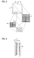
- FIG. 3 is a front view of an optical filter provided for the imaging device 10 illustrated in FIG. 1 , according to the present example embodiment.
- FIG. 4 is a sectional view of an optical filter, an imaging element, and a substrate provided for the imaging device 10 illustrated in FIG. 1 , according to the present example embodiment.
- a filter substrate 131 is a transparent substrate that transmits the incident light that has entered the optical filter 13 through an imaging lens.
- a polarizing-filter layer 132 is formed on the side of an imaging element 12 of the filter substrate 131. Further, a packed bed 133 is formed so as to cover the polarizing-filter layer 132.
- the light that has passed through the polarizing-filter layer 132 enters the pixels of the imaging element 12 on a substrate ST.
- An area-division polarizing filter with sub-wavelength structure (SWS) is provided for the polarizing-filter layer 132 by a polarizer corresponding to the pixel size of the imaging element 12.
- rectangular S-polarized-component transmissive areas POL1 and P-polarized-component transmissive areas POL2 are alternately arranged in a lateral direction (i.e, row direction) as a polarizer. Accordingly, vertically-arranged pixels PC1 and PC2 of the imaging element 12 face the S-polarized-component transmissive area POL1, and vertically-arranged PC3 and PC4 placed next to the pixels PC1 and PC2 on the right side face the P-polarized-component transmissive area POL2.
- the output of the photoelectric conversion from the pixels PC1 and PC2 includes S-polarized component data, and does not include P-polarized component data
- the output of the photoelectric conversion from the pixels PC3 and PC4 includes P-polarized component data, and does not include S-polarized component data.
- a mean value of the P-polarized component data of the two pixels on both sides i.e., a mean value of the output of the photoelectric conversion from the two pixels PC3 and PC4 on the right side and the output of the photoelectric conversion from the two pixels on the left side of the pixels PC1 and PC2, is used as the P-polarized component data of the pixels PC1 and PC2.
- a mean value of the S-polarized component data of the two pixels on both sides i.e., a mean value of the output of the photoelectric conversion from the two pixels PC1 and PC2 on the left side and the output of the photoelectric conversion from the two pixels on the right side of the pixels PC3 and PC4, is used as the S-polarized component data of the pixels PC3 and PC4. Similar processes are applied to the other pixels,
- the P-polarized image is the output of the photoelectric conversion including the P-polarized component data
- the S-polarized image is the output of the photoelectric conversion including the S-polarized component data.
- a differential polarized image is formed by the output of the photoelectric conversion from the pixels PC1 and PC2 not including the P-polarized component data and the output of the photoelectric conversion from the pixels PC3 and PC4 not including the S-polarized component data.
- Such a differential polarized image is used for various kinds of data detection.
- a monochrome sensor is assumed as an imaging element, but no limitation is indicated therein and a color sensor may be used.
- FIG. 5 is a functional block diagram of the windscreen correction unit 20 illustrated in FIG. 1 , according to the present example embodiment. As illustrated in FIG. 5 , the windscreen correction unit 20 includes an amplifier 21, and an amplification factor calculation unit 22.
- a pixel position data generator 15 is provided inside the imaging device 10.
- the pixel position data generator 15 generates pixel position data indicating the on-image positions of the pixels of an S-polarized image I 0 S, and transmits the generated pixel position data to the amplifier 21 through the amplification factor calculation unit 22.
- a parameter storage unit 230a that serves as a correction parameter storage unit is arranged in the ROM 230.
- the amplification factor calculation unit 22 reads correction parameters that are set and stored in advance in the parameter storage unit 230a, from the parameter storage unit 230a.
- the pixel position data generator 15 may be provided in the computer system 200.
- the amplification factor calculation unit 22 refers to the pixel position data and the correction parameters to calculate an amplification factor of the amplifier 21, and sets the calculated amplification factor to the amplifier 21.
- the S-polarized image I 0 S is input to the amplifier 21, and the intensity of the S-polarized component data of the S-polarized image I 0 S is amplified at a prescribed amplification factor set by the amplification factor calculation unit 22. As a result, an S-polarized image I 1 S is generated and output.
- a P-polarized image I 0 P is directly output as a P-polarized image I 1 P.
- a P-polarized image may be attenuated at a prescribed attenuation factor and an S-polarized image may be directly output just as it is, or both a P-polarized image and an S-polarized image may be processed, as will be described later.
- the correction parameters stored in the parameter storage unit 230a are prescribed in view of the on-image positions of the pixels of the S-polarized image I 0 S, the angle of inclination of the windscreen, or the like. Note that these positions of the pixels of the S-polarized image I 0 S correspond to the angles of incidence with reference to the optical axis of the imaging device 10.
- the correction parameters and the calculation algorithm used by the amplification factor calculation unit 22 are described later in detail.
- FIG. 6 illustrates a light beam that passes through a windscreen and enters the imaging device 10 horizontally to the optical axis of the imaging device 10 (i.e., a light beam directed to the center of the vertical angle of view of the imaging device 10), according to the present example embodiment.
- FIG. 7 illustrates a light beam that passes through a windscreen and enters the imaging device 10 obliquely to the optical axis of the imaging device 10 (i.e., a light beam not directed to the center of the vertical angle of view of the imaging device 10), according to the present example embodiment.
- the reflective index of the windscreen 60, and the angle of inclination of the windscreen 60 are referred to as n and ⁇ f , respectively.
- the incidence angle of a light beam 71 that enters the imaging device horizontally to the optical axis of the imaging device 10 with reference to a first surface 60, and the incidence angle with reference to the air (i.e., the exiting angle with reference to a second surface 62) are referred to as ⁇ i1 and ⁇ i2 , respectively.
- R 1S and R1P of the S-polarized component and P-polarized component on the first surface 61 are expressed by the following Equations (3) and (4).
- R 1 ⁇ S cos ⁇ i ⁇ 1 - ncos ⁇ i ⁇ 2 / cos ⁇ i ⁇ 1 + ncos ⁇ i ⁇ 2 2
- R 1 ⁇ P cos ⁇ i ⁇ 2 - ncos ⁇ i ⁇ 1 / cos ⁇ i ⁇ 1 + ncos ⁇ i ⁇ 2 2
- R 2S and R 2P of the S-polarized component and P-polarized component on the second surface 62 are expressed by the following Equations (5) and (6), respectively.
- R 2 ⁇ S ncos ⁇ i ⁇ 2 - cos ⁇ i ⁇ 1 / ncos ⁇ i ⁇ 2 + cos ⁇ i ⁇ 1 2
- R 2 ⁇ P ncos ⁇ i ⁇ 1 - cos ⁇ i ⁇ 2 / ncos ⁇ i ⁇ 2 + cos ⁇ i ⁇ 1 2
- T S 1 - R 1 ⁇ S ⁇ 1 - R 2 ⁇ S
- T P 1 - R 1 ⁇ P ⁇ 1 - R 2 ⁇ P
- Equation (9) an incidence angle ⁇ s defined by the following Equation (9) is used,
- Equations (2) to (8) are applicable to the case of FIG. 7 .
- ⁇ i ⁇ 1 ⁇ / 2 - ⁇ f + ⁇ s
- Ts, T P transmittance
- SDOP square-OP
- P/S polarization ratio
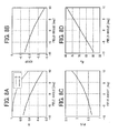
- "Field angle" of the lateral axis of the graph indicates the angle of view of the imaging device 10 (i.e., the inclination from the optical axis) in the vertical direction, where positive and negative values indicate upward directions (corresponding to the upper half of the screen) and downward directions (corresponding to the down half of the screen), respectively.
- P/S ranges from about 2.2 to 1.3 between the upper half and the down half of the screen. Because very slight difference is to be detected in the polarization data, this range is considered significantly large. This is because the incidence angle ⁇ i1 to the windscreen 60 is about 60° to 80° (see FIG. 8D ), and the reflectivity of the S-polarized component is large.
- the influence of the windscreen 60 on the intensity of polarized components varies widely depending on the vertical position of the screen, i.e., the incidence angle of the light beam. For this reason, the conventional technology in which correction is evenly performed over the screen is not sufficient to achieve desired effects.
- the incidence angle ⁇ i1 to the windscreen 60 is about 50° to 70° (see FIG. 9D ), which is smaller than the incidence angle ⁇ i1 of FIG. 8D .
- the amount of change in P/S illustrated in FIG. 9C is smaller than that of FIG. 8C .
- the range of P/S is still large.
- the amplifier 21 of the windscreen correction unit 20 amplifies the intensity of the S-polarized component such that the values of P/S illustrated in FIG. 8C and FIG. 9C , i.e., the ratio of the intensity of the P-polarized component to the intensity of the S-polarized component in the light beam that has passed through the windscreen, become constant regardless of the value of "Field angle".
- P/S may be set to any fixed value.
- Equation (10) may be used to correct the S-polarized image I 0 S.
- I 1 ⁇ S x y I 0 ⁇ S x y * d s * y / y max + c s
- I 0 S(x, y) and I 1 S(x, y) indicate the intensity of the S-polarized component data in the pixels at the screen coordinates (x, y) of the S-polarized images I 0 S and I 1 S, respectively.
- the point of origin of the screen coordinates (x, y) are at the top-left end of the screen.
- d s and c s are the parameters that define the inclination and y intercept of the linear function
- y max indicates the y coordinates of the bottom end of the screen.
- (y/y max ) is obtained by converting angle of view (Field angle) of the imaging device 10 so as to be 0 and 1 at the top end and bottom end of the screen, respectively.
- (y/y max ) is a correction parameter that indicates the relationship between the pixel position data of the S-polarized image and incidence angle formed with the optical axis of the imaging device 10.
- d s and c s are uniquely determined values by, for example, experiments, for the type of the windscreen.
- y max is determined such that the value of ⁇ d s *(y/y max )+c s ⁇ becomes equal to or greater than 0 and equal to or less than 1.
- y max ranges from 0 to 1 if the maximum value is set to 1, but if the maximum value has a fixed value as described above, y max has a value according to that fixed value.
- the amplification factor calculation unit 22 of the windscreen correction unit 20 calculates the value of ⁇ d s *(y/y max )+c s ⁇ as an amplification factor of the amplifier 21, and sets the calculated amplification factor to the amplifier 21.
- y max is prescribed and is stored in the parameter storage unit 230a in advance.
- y is input as pixel position data.
- the P-polarized image I 0 P may be attenuated by using the following Equation (11).
- I 1 ⁇ P x y I 0 ⁇ P x y * d P * y / y max + c P
- a correction table where d s as described above or d P in Equation (11) is the function of y may be used. If a plurality of pairs of d s or c s are set to the parameter storage unit 230a according to the angle ⁇ f of the windscreen, it becomes possible to deal with cases where the angle ⁇ f of the windscreen varies. In a similar manner, if a plurality of pairs of d s or c s are set to the parameter storage unit 230a according to the angles of view or the number of the pixels in the vertical direction of the imaging device 10, it becomes possible to deal with cases where the angles of view or the number of the pixels in the vertical direction of the imaging device 10 varies.
- the intensity of the polarized component data is corrected based on the positions of the pixels of a polarized image and the relationship between the intensity of the polarized components of the incident light to these positions of the pixels and the angle of inclination of the windscreen 60. Accordingly, the intensity of the polarized component data included in the polarized image is corrected to correspond to the intensity of the polarized component of the incident light that has not passed through the windscreen 60.
- the reflectance characteristic of the surface of object is expressed by bi-directional reflectance distribution function (BRDF).
- BRDF bi-directional reflectance distribution function
- FIG. 10 illustrates a model of reflection on an object OB, according to the present example embodiment of the present invention.
- N indicates the "outward normal vector" at a reflection point on the object OB.
- L indicates the "light source vector” that is directed to the light source from the reflection point.
- V indicates the "line-of-vision vector” that is directed to the observation position from the reflection point.
- H indicates the "bisection vector” that bisects the angle which the light source vector L forms with the line-of-vision vector V. Note that the vectors: N, L, V, and H are coplanar. On the same plane, angles: ⁇ , ⁇ L , ⁇ , ⁇ i , and ⁇ are defined as follows as illustrated in FIG. 10 .
- S-polarized light BRDF: ⁇ s( ⁇ , ⁇ )" by the object OB is defined by the following Equation (12), and "P-polarized light BRDF: ⁇ P ( ⁇ , ⁇ ) by the object OB is defined by the following Equation (13).
- ⁇ S ⁇ ⁇ k S ⁇ R S ⁇ i ⁇ D + k d ⁇ cos ⁇ L
- P ⁇ ⁇ k P ⁇ R P ⁇ i ⁇ D + k d ⁇ cos ⁇ L
- the first members of the right side of the Equations (12) and (13) are members of specular reflection model (Torrance-Sparrow model), and the second members of the right side of the Equations (12) and (13) are members of diffuse reflection model (Lambert model).
- the members ks, k P , and k d indicate a specular reflection coefficient of the S-polarized light, a specular reflection coefficient of the P-polarized light, and a diffuse reflection coefficient, respectively.
- R S ( ⁇ i ) and R P ( ⁇ i ) indicate the "Fresnel reflection formula" with reference to the S-polarized light and the P-polarized light, respectively.
- R S ( ⁇ i ) and R P ( ⁇ i ) are defined by the following Equations (14) and (15).
- n 1 and n 2 indicate the reflective indexes of the air and the object OB, respectively.
- the angle: ⁇ i ' has a relationship with the angle: ⁇ i and the reflective indexes: n 1 and n 2 as in the following Equation (16).
- ⁇ i ' is defined as in the following Equation (17).
- ⁇ i ⁇ ⁇ sin - 1 n 1 / n 2 ⁇ sin ⁇ i
- Equation (12) The member D in the Equations (12) and (13) indicates the "normal-line distribution member" of a minute area at the reflection point, and is defined by the following Equation (18).
- D exp - ⁇ 2 / 2 ⁇ a 2
- ⁇ indicates the central coordinate value of the distribution function, and corresponds to the angle parameter: ⁇ illustrated in FIG. 10 .
- a indicates a standard deviation in the distribution function, “a” also serves as a "parameter of angular distribution” on the minute area.
- the normal-line distribution: D is a Gaussian distribution that has a normal distribution.
- polarization data to be superposed on a brightness image is described.
- Various kinds of polarization data may be used, but “degree of polarization”, “sub-degree of polarization (SDOP)”, and “polarization ratio” are described below as the polarization data.
- the degree of polarization is defined by known Stokes parameters: S 0 , S1, S 2 , and S3, which relate to the polarization.
- the DOP is defined by the following Equation (19) with the Stokes parameters: S 0 , S 1 , S 2 , and S 3 .
- DOP ⁇ S 1 2 + S 2 2 + S 3 2 / S 0
- I(0, ⁇ ) and I(90, ⁇ ) indicate the light intensity through a polarizer when the axial angle is zero degree and the light intensity through a polarizer when the axial angle is ninety degree, respectively.
- I(0, ⁇ ) and I(90, ⁇ ) indicate the light-receptive intensity of a pixel that has received the transmission light through the S-polarized-component transmissive area POL1, and the light-receptive intensity of a pixel that has received the transmission light through the P-polarized-component transmissive area.
- the SDOP in this case is also referred to as "degree of polarization”.
- Polarization ratio is a ratio of I(0, ( ⁇ ) to I(90, ⁇ ), and is defined by the following Equation (22).
- Polarization Ratio I 0 ⁇ / I 90 ⁇
- the polarization ratio is a ratio of I(0, ⁇ ) to I(90, ⁇ ) as described above, the polarization ratio may be defined by the following Equation (23) in place of Equation (22).
- Polarization Ratio I 90 ⁇ / I 0 ⁇
- the brightness-polarization superposition unit 30 may superimpose any desired one of the three kinds of polarization data (DOP, SDOP, and polarization ratio) on the brightness data to obtain the output image I 2 described above.
- the brightness data may be obtained as follows.
- the polarizing-filter layer 132 provided for the imaging device 10 illustrated in FIG. 1 is an "area-division polarizing filter".
- polarizing-filter elements that transmit the P-polarized components and polarizing-filter elements that transmit the S-polarized components are two-dimensionally arranged on the polarizing-filter layer 132.
- the imaging area of the imaging element 12 is expressed by two-dimensional (x, y) coordinates (i.e., the screen coordinates described above), and the intensity of the S-polarized component and the P-polarized component received by the pixel at the position: (x, y) is referred to by I S (x, y) and I P (x, y), respectively.
- I bright (x, y) is expressed by the following Equation (24).
- I bright x y I S x y + I P x y / 2
- any of the DOP, SDOP, and polarization ratio may be used as the polarization data.
- the superposition may be performed by various types of calculation. In particular, calculating a linear sum and multiplication are easily achieved.
- a linear-sum method is expressed by the following Equation (26).
- I bright x y ⁇ SPI ⁇ Polarization Data I bright x y + Kx Polarization Data
- a multiplication method is expressed by the following Equation (27).
- I bright x y ⁇ SPI ⁇ Polarization Data I bright x y + xKx Polarization Data
- Equations (26) and (27) the polarization data is superposed on a brightness image as a change in brightness on each pixel. Accordingly, in the right side of Equations (26) and (27), a pixel to be added or multiplied has equal coordinates (x, y). Note that K in the right side of Equations (26) and (27) is a constant indicating the degree of the superposition and may have a desired value according to specific conditions of the superposition.
- the polarization state of the reflection light may be expressed by variables of the material of the object OB (reflective index, state of surface, inner-dispersion coefficient), the angle which the light source forms with the object, and the angle which the object forms with the observation point.
- the polarization state may be expressed by the following Equation (28).
- Polarization State F ⁇ Light - source State , Material , Angle
- Equation (28) F indicates a function.
- Equation (28) the variables are defined as follows. When any two of the light-source state, the material, and the angle are determined, the other one is determined accordingly.
- the members (Rs, Rp) that indicate "specular light of regular reflection" on the surface of the object OB characterize the polarization state.
- the imaging device 10 and the light source form the same angle with the object OB to be observed, almost no specular light is reflected. As a result, "polarization data is not obtained”.
- the polarization state is defined as in Equation (28), in vehicle-installed cameras that do not project irradiation light, "the polarization data of a polarized image” varies depending on the light-source state.
- the polarization data e.g., SDOP
- the polarization data also varies depending on the angle, the variations in polarization data due to the angle may be ignored when "objects on the road with the same angle" are to be observed.
- the intensity of reflection (rotatory power) of the S-polarized component and P-polarized component varies depending on the angle of the light (i.e., angle: ⁇ in FIG. 10 determined by angle: ⁇ L ).
- the rotatory power of the P-polarized light is always greater than that of the S-polarized light.
- the "difference in rotatory power" between the S-polarized component and the P-polarized component is greater as the surface reflection is greater (i.e., as the inner dispersion is smaller).
- the SDOP greatly varies depending on the angle: ⁇ of the light source. However, when the relationship between materials A and B with a certain angle is A>B in size, A>B holds true with other angles.
- the SDOP is greatly dependent on Kd of the material of an object to be captured and "the degree of Kd". For example, when an offset is zero with reference to the SDOP of the material A, whether the SDOP of the material B is on the positive side or on the negative side is not usually dependent on the angle of the light source.
- the SDOP becomes close to zero in a direct-light state. For this reason, when the SDOP is used as polarization data, a feature becomes no longer influenced by polarization as the light-source state shifts to a direct-light state and the polarization data becomes no longer useful.
- I bright_por (x, y) to which polarization data is added is defined as in the following Equation (29).
- I bright_por x y I bright x y + k ⁇ SDOP x y - ⁇ x X ⁇ y Y SDOP x y X ⁇ Y
- SDOP(x, y) I S x y - I P x y / I S x y + I P x y
- FIG. 11 is a functional block diagram of a brightness-polarization superposition unit that performs the processes of Formula 25 described above, according to the present example embodiment.
- the brightness-polarization superposition unit 30 includes a data generator 31, an offset removal unit 32, a superimposition unit 33, and a direct-light/back-light determination unit 34.
- the data generator 31 generates a brightness image and polarization data from the input image I 1 .
- the brightness image is generated using Equation (24).
- the SDOP as the polarization data is generated using Equation (30).
- I S (x, y) and I P (x, y) in these equations correspond to I 1 S(x, y) and I 1 P(x, y) described above in " ⁇ Intensity Correction of Polarized Component Data>".
- the brightness image is input to the superimposition unit 33 just as it is.
- the polarization data is input to the offset removal unit 32.
- the functions of the direct-light/back-light determination unit 34 are described later.
- the offset removal unit 32 performs "the second member in the square brackets" in the second member on the right side of Equation (29) for the input polarization data (SDOP). Then, the obtained calculation result is subtracted from the input polarization data (SDOP).
- Equation (29) With the second member in the square brackets on the right side of Equation (29), "an average of the SDOP" within an area determined by X and Y on an image is calculated. Note that any area of X and Y may be determined.
- the image area determined by X and Y is an area from which the area of the sky is removed from the entirety of the screen.
- Such an average of an image area as calculated above is an "offset", and the offset removal unit 32 subtracts the offset from the polarization data.
- the polarization data from which the offset has been removed is input to the superimposition unit 33, and is superimposed on the brightness data.
- This superimposition is performed by calculating a linear sum of the brightness data: I bright (x, y) and "the value in the square brackets on the right side of Equation (29)" from which the offset has been removed, as depicted in the right side of Equation (29).
- Equation (29) the value in the square brackets is multiplied by the coefficient: k that is placed before the square brackets of the second member on the right side of Equation (29).
- the coefficient: k is defined by the following Equations (31) and (32).
- SDOP x y - ⁇ x X ⁇ y Y SDOP x y X ⁇ Y k k 1 if ⁇ TH except cases of direct light
- SDOP x y - ⁇ x X ⁇ y Y SDOP x y X ⁇ Y k k 2 if ⁇ TH cases of direct light
- Equation (31) and (32) The calculation of Equation (31) and (32) is performed by the direct-light/back-light determination unit 34.
- k1 and k2 are "polarization data superimposition coefficients”.
- TH indicates a "threshold” that is determined such that "the direct-light state is recognizable”.
- the direct-light/back-light determination unit 34 determines that the light-source state is in the direct-light state when the "offset" is smaller than the threshold: TH, and sets the polarization data superimposition coefficient: k to k2.
- the direct-light/back-light determination unit 34 determines that the light-source state is not in the direct-light state when the "offset" is greater than the threshold: TH, and sets the polarization data superimposition coefficient: k to k1.
- the image area determined by X and Y used for calculating an average (i.e., an offset) may be the entirety of the screen including the area of the sky.
- an offset i.e., an offset
- the SDOP is used as the polarization data.
- the DOP or polarization ratio described above may be used as the polarization data in Formula (29).
- noise reduction processes be performed for the obtained image with "polarization data such as SDOP". For example, calculation of a weighted average, a median filter, or a " ⁇ filter” may be used to perform such noise reduction processes.
- the obtained polarized image includes , for example, a "saturated area" in the obtained polarized image.
- a "saturated area" in the obtained polarized image.
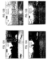
- FIGS. 12A and 12B are examples of the brightness image and the polarized-light superposed image, respectively, which are directly captured without any windscreen by the imaging device 10 without operating the windscreen correction unit 20, according to the present example embodiment.
- FIGS. 13A and 13B are examples of the brightness image and the polarized-light superposed image, respectively, which are captured through a windscreen by the imaging device 10 without operating the windscreen correction unit 20, according to the present example embodiment.
- FIGS. 14A and 14B are examples of the polarized-light superposed image, which are captured through a windscreen by the imaging device 10 with operating the windscreen correction unit 20, according to the present example embodiment.
- the location is a parking lot. There are trees ahead of the parking lot, and an apartment building is located on the right side of the trees. When these pictures were taken, the weather was light rain, and the road was wet. There were two vehicles in the parking lot.
- FIG. 12A is a brightness image
- FIG. 12B is a polarized-light superposed image.
- the road surface of the parking lot is very bright, and the trees ahead of the road is very dark in the brightness image.
- the apartment building is slightly dark in the brightness image.
- the road surface of the parking lot is quite dark, and the trees ahead of the road is slightly bright, in the polarized-light superposed image.
- the contrast between the road surface and the other areas is clear. Accordingly, it is easy to extract the area of the road surface.
- FIG. 13A is a brightness image
- FIG. 13B is a polarized-light superposed image.
- both the road surface and the other areas are darker than those of the brightness image of FIG. 12A .
- the contrast between the road surface and the other areas is still sufficient to extract the area of the road surface easily.
- the road surface and the other areas are almost equally dark, and the contrast between the road surface and the other areas is not clear. Accordingly, it is difficult to extract the area of the road surface.
- c s 1.2
- the contrast between the road surface and the other areas is improved in the polarized-light superposed images of FIGS. 14A and 14B .
- the data generator 31 of the brightness-polarization superposition unit 30 generates a brightness image from the average of the S-polarized image and the P-polarized image.
- the generation of such a brightness image may be performed by the imaging device 10 or the combination between the imaging device 10 and the windscreen correction unit 20.
- the windscreen correction unit 20 corrects the S-polarized image or the P-polarized image, but the windscreen correction unit 20 may correct the polarization data (SDOP, DOP) that are not yet superimposed on a brightness image.
- the imaging device 10 obtains a P-polarized component for the pixel that includes the S-polarized component but the P-polarized component, and obtains a P-polarized component for the pixel that includes the P-polarized component but the S-polarized component.
- obtaining processes of a P-polarized component may be performed by the combination between the imaging device 10 and the windscreen correction unit 20.
- the windscreen correction unit 20, the brightness-polarization superposition unit 30, the image processing/image recognition unit 40, and the vehicle controller 50 may be integrated into the imaging device 10.
- a device that includes an area-division polarizing filter with sub-wavelength structure (SWS) is used as the imaging device 10.
- the imaging device 10 may be used as the imaging device 10 as long as a polarized image can be captured.
- various kinds of polarizing cameras e.g., a camera having a polarizer in front of the lens for capturing a plurality of images whose polarizing angles are different from each other
- JP-2011-150687 may be used as the imaging device 10.
- actual windscreens are slightly bent in the lateral direction. For this reason, more precise polarization data may be obtained if correction is performed in view of the lateral positions on an image (x-coordinate).
- any one of the above-described and other methods of the present invention may be embodied in the form of a computer program stored in any kind of storage medium.
- storage mediums include, but are not limited to, flexible disk, hard disk, optical discs, magneto-optical discs, magnetic tapes, nonvolatile memory cards, ROM, etc.
- any one of the above-described and other methods of the present invention may be implemented by ASICs, prepared by interconnecting an appropriate network of conventional component circuits, or by a combination thereof with one or more conventional general-purpose microprocessors and/or signal processors programmed accordingly.
- the present invention can be implemented in any convenient form, for example using dedicated hardware, or a mixture of dedicated hardware and software.
- the present invention may be implemented as computer software implemented by one or more networked processing apparatuses.
- the network can comprise any conventional terrestrial or wireless communications network, such as the Internet.
- the processing apparatuses can compromise any suitably programmed apparatuses such as a general purpose computer, personal digital assistant, mobile telephone (such as a WAP or 3G-compliant phone) and so on. Since the present invention can be implemented as software, each and every aspect of the present invention thus encompasses computer software implementable on a programmable device.
- the computer software can be provided to the programmable device using any conventional carrier medium.
- the carrier medium can compromise a transient carrier medium such as an electrical, optical, microwave, acoustic or radio frequency signal carrying the computer code.
- a transient carrier medium such as an electrical, optical, microwave, acoustic or radio frequency signal carrying the computer code.
- An example of such a transient medium is a TCP/IP signal carrying computer code over an IP network, such as the Internet.
- the carrier medium can also comprise a storage medium for storing processor readable code such as a floppy disk, hard disk, CD ROM, magnetic tape device or solid state memory device.
- the hardware platform includes any desired kind of hardware resources including, for example, a central processing unit (CPU), a random access memory (RAM), and a hard disk drive (HDD).
- the CPU may be implemented by any desired kind of any desired number of processor.
- the RAM may be implemented by any desired kind of volatile or non-volatile memory.
- the HDD may be implemented by any desired kind of non-volatile memory capable of storing a large amount of data.
- the hardware resources may additionally include an input device, an output device, or a network device, depending on the type of the apparatus. Alternatively, the HDD may be provided outside of the apparatus as long as the HDD is accessible.
- the CPU such as a cache memory of the CPU
- the RAM may function as a physical memory or a primary memory of the apparatus, while the HDD may function as a secondary memory of the apparatus.
Landscapes
- Engineering & Computer Science (AREA)
- Physics & Mathematics (AREA)
- General Physics & Mathematics (AREA)
- Theoretical Computer Science (AREA)
- Multimedia (AREA)
- General Health & Medical Sciences (AREA)
- Health & Medical Sciences (AREA)
- Vascular Medicine (AREA)
- Signal Processing (AREA)
- Studio Devices (AREA)
- Microscoopes, Condenser (AREA)
- Image Processing (AREA)
- Length Measuring Devices By Optical Means (AREA)
Applications Claiming Priority (2)
| Application Number | Priority Date | Filing Date | Title |
|---|---|---|---|
| JP2013266073 | 2013-12-24 | ||
| JP2014208293A JP6379966B2 (ja) | 2013-12-24 | 2014-10-09 | 画像処理装置、画像処理システム、画像処理方法、画像処理プログラム、及び移動体制御装置 |
Publications (2)
| Publication Number | Publication Date |
|---|---|
| EP2889807A2 true EP2889807A2 (de) | 2015-07-01 |
| EP2889807A3 EP2889807A3 (de) | 2015-08-05 |
Family
ID=52146262
Family Applications (1)
| Application Number | Title | Priority Date | Filing Date |
|---|---|---|---|
| EP14199381.6A Withdrawn EP2889807A3 (de) | 2013-12-24 | 2014-12-19 | Bildverarbeitungsvorrichtung, Bildverarbeitungssystem, mobile Objektsteuerungsvorrichtung, Bilderverarbeitungsverfahren und Trägermedien |
Country Status (2)
| Country | Link |
|---|---|
| EP (1) | EP2889807A3 (de) |
| JP (1) | JP6379966B2 (de) |
Cited By (6)
| Publication number | Priority date | Publication date | Assignee | Title |
|---|---|---|---|---|
| CN111639638A (zh) * | 2020-05-29 | 2020-09-08 | 佛山市南海区广工大数控装备协同创新研究院 | 一种识别透明平板的系统以及识别方法 |
| CN112637387A (zh) * | 2019-10-07 | 2021-04-09 | 索尼半导体解决方案公司 | 电子设备 |
| CN112651911A (zh) * | 2020-12-01 | 2021-04-13 | 广东工业大学 | 一种基于偏振图像的高动态范围成像生成方法 |
| US11062170B2 (en) | 2017-02-15 | 2021-07-13 | Sony Corporation | Information processing apparatus, information processing method, and imaging apparatus |
| CN113557709A (zh) * | 2019-04-19 | 2021-10-26 | 索尼集团公司 | 成像装置、图像处理装置和图像处理方法 |
| CN114556132A (zh) * | 2019-10-16 | 2022-05-27 | 伟摩有限责任公司 | 用于红外感测的系统和方法 |
Families Citing this family (2)
| Publication number | Priority date | Publication date | Assignee | Title |
|---|---|---|---|---|
| JP7013651B2 (ja) * | 2017-02-06 | 2022-02-01 | 株式会社リコー | サーバ装置、判別プログラム及び判別システム |
| JP7732420B2 (ja) * | 2022-08-25 | 2025-09-02 | トヨタ自動車株式会社 | 車載撮像装置 |
Citations (1)
| Publication number | Priority date | Publication date | Assignee | Title |
|---|---|---|---|---|
| JP2011150687A (ja) | 2009-12-25 | 2011-08-04 | Ricoh Co Ltd | 立体物識別装置、並びに、これを備えた移動体制御装置及び情報提供装置 |
Family Cites Families (2)
| Publication number | Priority date | Publication date | Assignee | Title |
|---|---|---|---|---|
| JP3341664B2 (ja) * | 1997-12-15 | 2002-11-05 | トヨタ自動車株式会社 | 車両用ライン検出装置及び路上ライン検出方法並びにプログラムを記録した媒体 |
| JP2011258144A (ja) * | 2010-06-11 | 2011-12-22 | Toshiba Corp | 画像撮影装置、画像補正処理方法及び画像補正処理プログラム |
-
2014
- 2014-10-09 JP JP2014208293A patent/JP6379966B2/ja not_active Expired - Fee Related
- 2014-12-19 EP EP14199381.6A patent/EP2889807A3/de not_active Withdrawn
Patent Citations (1)
| Publication number | Priority date | Publication date | Assignee | Title |
|---|---|---|---|---|
| JP2011150687A (ja) | 2009-12-25 | 2011-08-04 | Ricoh Co Ltd | 立体物識別装置、並びに、これを備えた移動体制御装置及び情報提供装置 |
Cited By (8)
| Publication number | Priority date | Publication date | Assignee | Title |
|---|---|---|---|---|
| US11062170B2 (en) | 2017-02-15 | 2021-07-13 | Sony Corporation | Information processing apparatus, information processing method, and imaging apparatus |
| CN113557709A (zh) * | 2019-04-19 | 2021-10-26 | 索尼集团公司 | 成像装置、图像处理装置和图像处理方法 |
| CN112637387A (zh) * | 2019-10-07 | 2021-04-09 | 索尼半导体解决方案公司 | 电子设备 |
| CN114556132A (zh) * | 2019-10-16 | 2022-05-27 | 伟摩有限责任公司 | 用于红外感测的系统和方法 |
| CN111639638A (zh) * | 2020-05-29 | 2020-09-08 | 佛山市南海区广工大数控装备协同创新研究院 | 一种识别透明平板的系统以及识别方法 |
| CN111639638B (zh) * | 2020-05-29 | 2023-04-18 | 佛山市南海区广工大数控装备协同创新研究院 | 一种识别透明平板的系统以及识别方法 |
| CN112651911A (zh) * | 2020-12-01 | 2021-04-13 | 广东工业大学 | 一种基于偏振图像的高动态范围成像生成方法 |
| CN112651911B (zh) * | 2020-12-01 | 2023-10-13 | 广东工业大学 | 一种基于偏振图像的高动态范围成像生成方法 |
Also Published As
| Publication number | Publication date |
|---|---|
| JP2015144421A (ja) | 2015-08-06 |
| JP6379966B2 (ja) | 2018-08-29 |
| EP2889807A3 (de) | 2015-08-05 |
Similar Documents
| Publication | Publication Date | Title |
|---|---|---|
| EP2889807A2 (de) | Bildverarbeitungsvorrichtung, Bildverarbeitungssystem, mobile Objektsteuerungsvorrichtung, Bilderverarbeitungsverfahren und Trägermedien | |
| EP3731180B1 (de) | Verfahren und vorrichtung zur zieldetektion | |
| CN105247847B (zh) | 图像处理系统 | |
| US8396319B2 (en) | Separation and contrast enhancement of overlapping cast shadow components and target detection in shadow using polarization | |
| US8099213B2 (en) | Road-edge detection | |
| JP5664152B2 (ja) | 撮像装置、車載用撮像システム及び物体識別装置 | |
| US8319854B2 (en) | Shadow removal in an image captured by a vehicle based camera using a non-linear illumination-invariant kernel | |
| US8983126B2 (en) | Method and system for detecting vehicle position by employing polarization image | |
| KR102383066B1 (ko) | 편광 이미지를 이용한 이미지 내 안개 제거 방법 및 시스템 | |
| JP2011165050A (ja) | 白線認識装置 | |
| CN106780385B (zh) | 一种基于湍流红外辐射模型的雾天降质图像清晰化方法 | |
| EP2889806A2 (de) | Bildverarbeitungsvorrichtung, Bildverarbeitungssystem, mobile Objektsteuerungsvorrichtung, Bilderkennungsverfahren und Trägeranordnung | |
| KR101348681B1 (ko) | 영상탐지시스템의 다중센서 영상정렬방법 및 이를 이용한 영상탐지시스템의 다중센서 영상정렬장치 | |
| Ren et al. | Investigation on principle of polarization-difference imaging in turbid conditions | |
| Wang et al. | Digital image forgery detection based on the consistency of defocus blur | |
| CN103559479B (zh) | 一种基于偏振度椭圆拟合的中性点识别方法 | |
| Buckel et al. | Spatially variant scattering-based single-image dust removal in agriculture | |
| CN108447025B (zh) | 一种基于单幅图像采集的偏振图像去雾方法 | |
| Gundawar et al. | Improved single image dehazing by fusion | |
| CN105678713A (zh) | 基于线性扩散板与反射分量分离理论的高光去除方法 | |
| JP2002286862A (ja) | 路面状態判別方法およびその装置 | |
| CN110146112A (zh) | 一种二维相敏解调方法及装置 | |
| JP2012185602A (ja) | 画像処理システム、画像処理装置、方法、プログラムおよび記録媒体 | |
| JP3495980B2 (ja) | 地表上に存在する人工物の検出方法および検出装置 | |
| CN1963391A (zh) | 基于偏振相位检测野外水体障碍物的方法 |
Legal Events
| Date | Code | Title | Description |
|---|---|---|---|
| PUAI | Public reference made under article 153(3) epc to a published international application that has entered the european phase |
Free format text: ORIGINAL CODE: 0009012 |
|
| 17P | Request for examination filed |
Effective date: 20141219 |
|
| AK | Designated contracting states |
Kind code of ref document: A2 Designated state(s): AL AT BE BG CH CY CZ DE DK EE ES FI FR GB GR HR HU IE IS IT LI LT LU LV MC MK MT NL NO PL PT RO RS SE SI SK SM TR |
|
| AX | Request for extension of the european patent |
Extension state: BA ME |
|
| PUAL | Search report despatched |
Free format text: ORIGINAL CODE: 0009013 |
|
| AK | Designated contracting states |
Kind code of ref document: A3 Designated state(s): AL AT BE BG CH CY CZ DE DK EE ES FI FR GB GR HR HU IE IS IT LI LT LU LV MC MK MT NL NO PL PT RO RS SE SI SK SM TR |
|
| AX | Request for extension of the european patent |
Extension state: BA ME |
|
| RIC1 | Information provided on ipc code assigned before grant |
Ipc: G01J 4/00 20060101ALI20150626BHEP Ipc: G06T 5/50 20060101ALI20150626BHEP Ipc: H04N 5/235 20060101ALI20150626BHEP Ipc: G06K 9/20 20060101ALI20150626BHEP Ipc: G06K 9/00 20060101AFI20150626BHEP |
|
| STAA | Information on the status of an ep patent application or granted ep patent |
Free format text: STATUS: EXAMINATION IS IN PROGRESS |
|
| 17Q | First examination report despatched |
Effective date: 20170306 |
|
| STAA | Information on the status of an ep patent application or granted ep patent |
Free format text: STATUS: THE APPLICATION IS DEEMED TO BE WITHDRAWN |
|
| 18D | Application deemed to be withdrawn |
Effective date: 20210701 |