EP2889708B1 - Elektronische Steuerung für eine Umwälzpumpe, Umwälzpumpe und entsprechendes Verfahren - Google Patents
Elektronische Steuerung für eine Umwälzpumpe, Umwälzpumpe und entsprechendes Verfahren Download PDFInfo
- Publication number
- EP2889708B1 EP2889708B1 EP14200222.9A EP14200222A EP2889708B1 EP 2889708 B1 EP2889708 B1 EP 2889708B1 EP 14200222 A EP14200222 A EP 14200222A EP 2889708 B1 EP2889708 B1 EP 2889708B1
- Authority
- EP
- European Patent Office
- Prior art keywords
- control
- data
- module
- parameterization
- electronic control
- Prior art date
- Legal status (The legal status is an assumption and is not a legal conclusion. Google has not performed a legal analysis and makes no representation as to the accuracy of the status listed.)
- Active
Links
Images
Classifications
-
- G—PHYSICS
- G05—CONTROLLING; REGULATING
- G05B—CONTROL OR REGULATING SYSTEMS IN GENERAL; FUNCTIONAL ELEMENTS OF SUCH SYSTEMS; MONITORING OR TESTING ARRANGEMENTS FOR SUCH SYSTEMS OR ELEMENTS
- G05B19/00—Programme-control systems
- G05B19/02—Programme-control systems electric
- G05B19/04—Programme control other than numerical control, i.e. in sequence controllers or logic controllers
- G05B19/042—Programme control other than numerical control, i.e. in sequence controllers or logic controllers using digital processors
- G05B19/0426—Programming the control sequence
-
- F—MECHANICAL ENGINEERING; LIGHTING; HEATING; WEAPONS; BLASTING
- F04—POSITIVE - DISPLACEMENT MACHINES FOR LIQUIDS; PUMPS FOR LIQUIDS OR ELASTIC FLUIDS
- F04D—NON-POSITIVE-DISPLACEMENT PUMPS
- F04D15/00—Control, e.g. regulation, of pumps, pumping installations or systems
- F04D15/0027—Varying behaviour or the very pump
-
- F—MECHANICAL ENGINEERING; LIGHTING; HEATING; WEAPONS; BLASTING
- F04—POSITIVE - DISPLACEMENT MACHINES FOR LIQUIDS; PUMPS FOR LIQUIDS OR ELASTIC FLUIDS
- F04D—NON-POSITIVE-DISPLACEMENT PUMPS
- F04D13/00—Pumping installations or systems
- F04D13/02—Units comprising pumps and their driving means
- F04D13/06—Units comprising pumps and their driving means the pump being electrically driven
Definitions
- the invention relates to an electronic control for a circulation pump.
- the invention further relates to a circulation pump and a method of controlling a circulation pump motor.
- a circulation pump also called a circulator
- Such pumps are thus present in domestic hot water installations or in domestic heating installations, whether heating oil, gas or solar energy.
- Such installations are carried out at the user's home, directly in the private part of the home or in the common areas of a co-ownership of the user's home.
- EP2573403A1 discloses an electric pump provided with a control device, said device having storage means and a microprocessor and being configured to receive data information.
- GILSON "333 and 334 Pumps User's Guide” (2000-02-01, XP055144342 ) discloses instructions for the safe use of Gilson brand pumps.
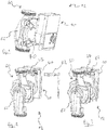
- FIG 1 shows a perspective view of a pump 60 comprising an electronic control 10 for controlling the driving motor 70 of the pump 60.
- the driving motor 70 drives a rotor provided with a blade wheel, not shown, for impelling the circulation of a fluid in the hydraulic body 62 of the pump 60.
- figure 2 shows a rear view of such a pump 60.
- the electronic control 10 comprises a number of connectors.
- the electronic control 10 comprises a first connector 47 for the power supply of the entire pump.
- the electronic control 10 further comprises electronic communication connectors with external members to the pump.
- These electronic communication connectors with external members to the pump comprise on the one hand the connector 40 for driving communication of the pump.
- This connector 40 is provided to receive a connection cable 82, as illustrated in FIG. figure 3 .
- This connection cable makes it possible, for example, to connect the electronic control unit 10 with a boiler of the domestic hydraulic installation which can transmit control data for example according to a thermostat of the domestic hydraulic installation.
- these electrical communication connectors with external members to the pump 60 also include a parametering connector.
- this parametering connector 45 allows the communication of parameterization data 90 to the electronic control 10.
- the electronic control 10 comprises a module 30 which receives its data 90 to allow the parameterization of a control module 20 of the control 10.
- the data control 80 received by the connector 40 are converted by the control module 20 into a hydraulic setpoint, from which the control module 20 drives the motor 70, the power being transmitted via a power connector 49 to the motor.
- These setting data 90 may be provided by an operator such as the hydraulic installation manufacturer depending on the characteristics of the pump and hydraulic installation envisaged. This data is typically communicated during factory assembly of the pump 60.
- the parametering connector 45 is not visible on the Figures 2 and 3 because this connector is rendered inaccessible to the user for aesthetic reasons. This inaccessibility poses a problem when a new parameterization of the pump 60 is necessary or when the parameterization of the pump does not take place in the factory but on the user's site.
- the electronic control is devoid of an electronic communication connector other than the connector to which the communication module is connected.
- control module is parameterized by the parameterization module for converting the control data distributed by the communication module into a hydraulic setpoint for controlling the driving motor of the pump.
- control module is adapted to receive control data, and, preferably, to transmit return data in the form of flow, power and pressure.
- control module is adapted to receive the control data in the form of pulse width modulation.
- the parameterization module is adapted to receive the parameterization data in the form of a universal asynchronous transceiver signal.
- the communication module is adapted to identify, by default, the received data as control data, and to identify, after reception of a switching signal, the received data as parameter data, at least for a period of determined time.
- the switching signal is a signal of frequency greater than 5000 Hz, preferably greater than or equal to 20000 Hz, and of duration greater than or equal to 100 ms.
- the communication module is adapted to identify the data as parameterization data following the switching signal and until no signal has been received for a predetermined period of time, preferably greater than or equal to 1 minute.
- the invention also proposes a circulation pump for a domestic hydraulic installation, said pump comprising a drive motor and the preceding electronic control adapted to control the drive motor.
- a circulation pump also designated by the term "hydraulic circulator" of a domestic hydraulic system for domestic hot water or for heating, that is to say in particular the hydraulic installations installed in the user's home.
- a hydraulic installation can thus correspond to a domestic hot water or heating system of any building, such as a residential building or office and especially such as a factory.
- This hydraulic installation does not, however, correspond to an industrial hydraulic installation.
- the nominal hydraulic power of the pump of the installation to be serviced can be between 1 and 2500 W.
- the circulation pump to be controlled corresponds to the circulation pump 60 illustrated in FIG. figure 1 to 3 , with the difference that the electronic control 10 is replaced by the proposed electronic control.
- the proposed electronic control is thus adapted to control a driving motor of the circulation pump.
- the drive motor drives a rotor equipped with a paddle wheel to impel the circulation of a fluid in the hydraulic body of the pump.
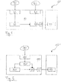
- the figure 5 shows a schematic view of the proposed electronic control 110 for controlling the pump 160 provided with the drive motor 170.
- the pump comprising the drive motor 170 and the proposed electronic control 110 for controlling the motor 170 is also provided.
- the electronic control 110 comprises a control module 120 of the motor 170 of the pump 160.
- the control module 120 converts control data, such as those sent by a boiler of the installation hydraulic, a hydraulic setpoint used to control the motor 170 of the pump 160.
- a hydraulic setpoint used to control the motor 170 of the pump 160.
- the control module 120 drives the engine 170 by a hydraulic setpoint, such as a hydraulic curve setpoint , a flow or pressure.
- the control module 120 can in particular be adapted to communicate bidirectionally.
- the control module can send data to the boiler of the hydraulic system such as the flow rate in the pump, the power consumed by the pump, or any other useful data for the boiler. and can be determined by the pump.
- the conversion of the control data into a hydraulic setpoint takes place according to the parameterization of this module 120.
- the operation of the pump 160 is indeed in particular conditioned by the programming parameters of the pump 160. These programming parameters of the pump 160 are chosen in particular according to the physical characteristics of the pump 160 and the characteristics of the hydraulic installation on the pump 160. which pump 160 is installed.
- the proposed command 110 comprises a parameterization module 130. According to the parameterization data received by the parameterization module 130, this module 130 parameterizes the control module 120, or modifies the parameterization of the control module 120.
- the proposed command 110 comprises an electronic communication connector 140 which receives both the parameterization data and both the control data.
- the control 110 comprises a communication module 150 connected to this connector 140.
- the modules 120, 130, and 150 can be integrated on the same electronic card , the notion of modules being particularly functional and not necessarily physical.
- This communication module 150 is adapted to distribute the setting data and control data, respectively to the parameterization module 130 and to the control module 120.
- the communication module 150 identifies the nature of the data provided.
- Such a method for controlling the motor 170 is also proposed by means of the proposed command 110 and comprising the supply of the data to the communication module 150 and the identification of the nature of these data by the communication module 150.
- 180 data supplied to the communication module 150 are identified as parameter data, the communication module 150 transmits these data to the parameterization module 130 which parameterizes the control module 120 or modifies the parameters of the control module 120.
- the communication module 150 transmits these data to the control module 120, which converts these data into a hydraulic setpoint according to its setting.
- the identification of the nature of the data 180 performed by the communication module 150 allows the proposed electronic control to include only one electronic communication connector with external organs to the pump.
- This single connector is the connector 140 and corresponds to the union of the connectors 45 and 40 previously illustrated in FIG. figure 4 .
- the connector 140 concentrates both the function of the parametering connector and the function of the control connector 40.
- this meeting of the external communication connectors in the only external communication connector 140 makes it possible to make the connector allowing the parameterization of the pump 160 more accessible to the user.
- the parameterization can then notably be envisaged on site, such as when troubleshooting and especially when replacing a pump damaged by a generic pump to set according to the characteristics of the hydraulic system to troubleshoot.
- the use of a single external communication connector as proposed also facilitates the design of the electronic control, including its housing, also designated housing. Even though the connector 140 is the only external communication connector, the proposed electronic control may also include connectors other than communication connectors.
- the command 110 can thus comprise a power transmission connector 149 to the pump motor 170, the transmitted power being controlled by the control module as a function of the received control data, via the hydraulic setpoint.
- the electronic control 110 may also include a power supply connector, similar to the known connector 47 illustrated in FIG. Figures 2 and 3 . According to the illustrated embodiment, since the connector 149 and the power supply connector are not communication connectors, the electronic control 110 does not have an electronic communication connector other than the connector 140. In other words, the control 110 may be devoid of electronic communication connector other than the connector 140 to which the communication module is connected.
- the control module 120 of the proposed electronic control 110 can in particular be adapted to receive control data in the form of pulse width modulation (also referred to as Pulse Width Modulation, abbreviated as PWM).
- the parameterization module 130 can be adapted to receive the parameterization data in the form of a universal asynchronous transceiver signal (signal or protocol also designated by the English term Universal Asynchronous Receiver Transmitter, abbreviated UART).
- UART Universal Asynchronous Receiver Transmitter
- the connector 140 is in any case designed to receive both types of data, control and parameterization.
- the connector 140 may in particular be of the PWM type, in particular bidirectional, the UART signals being able to pass through this type of connector.
- the communication module 150 identifies the data 180 as control data to be communicated to the control module 120. This identification can cease upon receipt of a switching signal in the data 180.
- the switching signal corresponds for example to a frequency signal greater than 5000 Hz, which corresponds to the upper limit of the PWM type signals.
- the switching signal may have a frequency greater than or equal to 20000Hz to differentiate well from the control signal frequencies which may be PWM signals. The frequency pitch alone may be sufficient to identify the switching signal.
- the frequency height may be associated with a certain duration of a switching signal, such as greater than or equal to 100 ms.
- the data 180 is identified by the communication module 150 as parameterization data to be transmitted to the parameterization module 130.
- Such an identification may remain for at least a predetermined duration and preferably for a predetermined period of time. after the absence of any signal.
- the communication module 150 identifies new data 180 as control data. This period of absence of received data 180, switching period, can be chosen greater than or equal to 1 minute.
- the pump 160 can be disconnected and then reconnected for the electronic control 110 to recognize the data supplied as control data by default.
- the present invention is not limited to the examples and the embodiment described and shown, but it is capable of many variants.
- the communication module 150 can identify the data 180 as parameterization data to be communicated to the parameterization module 120 and this for a certain predetermined duration, such as of the order of one minute. .
- This initial period of temporary and default identification of the data 180 as parameterization data makes it possible to simplify the communication module 150 which may not discriminate any differences in frequencies between control data and parameterization data.
Landscapes
- Engineering & Computer Science (AREA)
- Mechanical Engineering (AREA)
- General Engineering & Computer Science (AREA)
- Physics & Mathematics (AREA)
- General Physics & Mathematics (AREA)
- Automation & Control Theory (AREA)
- Control Of Electric Motors In General (AREA)
- Control Of Positive-Displacement Pumps (AREA)
Claims (9)
- Elektronische Steuerung (110) für eine Umwälzpumpe (160), umfassend einen Antriebsmotor (170), wobei die Steuerung aufweist:- ein Steuermodul (120) des Antriebsmotors (170) der Umwälzpumpe,- ein Parametrierungsmodul (130) des Steuermoduls,- einen elektrischen Kommunikationsstecker (140),- ein Kommunikationsmodul (150), das einerseits an den Stecker und andererseits an das Parametrierungs- und an das Steuermodul angeschlossen ist, wobei das Kommunikationsmodul geeignet ist, um∘ Parametrierdaten und Steuerdaten, die von dem Stecker empfangen werden, jeweils an das Parametrierungsmodul und an das Steuermodul zu verteilen und∘ standardmäßig die empfangenen Daten als Steuerdaten zu identifizieren und nach dem Empfangen eines Schaltsignals die empfangenen Daten mindestens während eines bestimmten Zeitraumes als Parametrierdaten zu identifizieren.
- Elektronische Steuerung (110) nach Anspruch 1, wobei das Steuermodul durch das Parametrierungsmodul konfiguriert ist, um die Steuerdaten, die von dem Kommunikationsmodul verteilt werden, in einen hydraulischen Sollwert zum Steuern des Antriebsmotors der Pumpe umzuwandeln.
- Elektronische Steuerung (110) nach Anspruch 2, wobei das Steuermodul geeignet ist, Steuerdaten zu empfangen und vorzugsweise Rückgabedaten in Form von Durchsatz, Leistung und Druck zu senden.
- Elektronische Steuerung (110) nach einem der Ansprüche 1 bis 3, wobei das Steuermodul geeignet ist, die Steuerdaten in Form von Pulsweitenmodulation zu empfangen.
- Elektronische Steuerung (110) nach einem der Ansprüche 1 bis 4, wobei das Parametrierungsmodul geeignet ist, die Parametrierdaten in Form von einem universellen asynchronen Sender-/Empfänger-Signal zu empfangen.
- Elektronische Steuerung (110) nach einem der Ansprüche 1 bis 5, wobei das Schaltsignal ein Signal mit einer Frequenz ist, die höher als 5.000 Hz, vorzugsweise höher als oder gleich 20.000 Hz ist, und mit einer Dauer, die größer oder gleich 100 ms ist.
- Elektronische Steuerung (110) nach einem der Ansprüche 1 bis 6, wobei das Kommunikationsmodul geeignet ist, die Daten als Parametrierdaten infolge des Schaltsignals und bis zur Abwesenheit des Empfangens von jeglichem Signal in einem vorgegebenen Zeitraum, vorzugsweise von gleich oder länger als 1 Minute, zu identifizieren.
- Umwälzpumpe (160) einer häuslichen Hydraulikanlage, wobei die Pumpe einen Antriebsmotor (170) und eine elektronische Steuerung nach einem der Ansprüche 1 bis 7 aufweist, die geeignet ist, den Antriebsmotor (170) zu steuern.
- Verfahren zum Steuern eines Antriebsmotors (170) einer Umwälzpumpe (160) mit Hilfe von einer elektronischen Steuerung (110) nach einem der Ansprüche 1 bis 7, wobei das Verfahren aufweist:- das Bereitstellen durch den Stecker (140) der elektronischen Steuerung der Parametrierdaten und der Steuerdaten dem Kommunikationsmodul (150) der elektronischen Steuerung,- das standardmäßige Identifizieren durch das Kommunikationsmodul (150) der bereitgestellten Daten als Steuerdaten,- das Identifizieren der bereitgestellten Daten als Parametrierdaten nach dem Empfangen eines Schaltsignals durch das Kommunikationsmodul (150) mindestens während eines bestimmten Zeitraumes,- das Parametrieren des Steuermoduls (120) mit Hilfe von dem Parametrierungsmodul (130), wenn die Daten, die dem Kommunikationsmodul bereitgestellt werden, als Parametrierdaten identifiziert werden, oder- das Steuern des Antriebsmotors (170) mit Hilfe von dem Steuermodul, wenn die Daten, die dem Kommunikationsmodul bereitgestellt werden, als Steuerdaten identifiziert werden.
Applications Claiming Priority (1)
| Application Number | Priority Date | Filing Date | Title |
|---|---|---|---|
| FR1363563A FR3015587B1 (fr) | 2013-12-24 | 2013-12-24 | Commande electronique pour une pompe de circulation, pompe de circulation et procede correspondant |
Publications (2)
| Publication Number | Publication Date |
|---|---|
| EP2889708A1 EP2889708A1 (de) | 2015-07-01 |
| EP2889708B1 true EP2889708B1 (de) | 2019-07-10 |
Family
ID=50473494
Family Applications (1)
| Application Number | Title | Priority Date | Filing Date |
|---|---|---|---|
| EP14200222.9A Active EP2889708B1 (de) | 2013-12-24 | 2014-12-23 | Elektronische Steuerung für eine Umwälzpumpe, Umwälzpumpe und entsprechendes Verfahren |
Country Status (2)
| Country | Link |
|---|---|
| EP (1) | EP2889708B1 (de) |
| FR (1) | FR3015587B1 (de) |
Families Citing this family (1)
| Publication number | Priority date | Publication date | Assignee | Title |
|---|---|---|---|---|
| CN105545763B (zh) * | 2015-12-13 | 2017-07-04 | 渤海大学 | 供水压力罐远程控制装置与控制方法 |
Citations (1)
| Publication number | Priority date | Publication date | Assignee | Title |
|---|---|---|---|---|
| EP2610500A1 (de) * | 2011-12-27 | 2013-07-03 | Grundfos Holding A/S | Pumpenaggregat |
Family Cites Families (2)
| Publication number | Priority date | Publication date | Assignee | Title |
|---|---|---|---|---|
| FR2815147B1 (fr) * | 2000-10-09 | 2003-09-05 | A F C A | Dispositif de commande de moyens d'entrainement ou d'actionnement comprenant une platine electronique de commande avec une memoire de transfert |
| EP2573403B1 (de) * | 2011-09-20 | 2017-12-06 | Grundfos Holding A/S | Pumpe |
-
2013
- 2013-12-24 FR FR1363563A patent/FR3015587B1/fr active Active
-
2014
- 2014-12-23 EP EP14200222.9A patent/EP2889708B1/de active Active
Patent Citations (1)
| Publication number | Priority date | Publication date | Assignee | Title |
|---|---|---|---|---|
| EP2610500A1 (de) * | 2011-12-27 | 2013-07-03 | Grundfos Holding A/S | Pumpenaggregat |
Also Published As
| Publication number | Publication date |
|---|---|
| FR3015587B1 (fr) | 2019-05-31 |
| FR3015587A1 (fr) | 2015-06-26 |
| EP2889708A1 (de) | 2015-07-01 |
Similar Documents
| Publication | Publication Date | Title |
|---|---|---|
| CN102003374B (zh) | 用于电机驱动器控制面板和驱动器终端的系统和方法 | |
| EP2265458A1 (de) | Hybridantrieb für hydraulikleistung | |
| CN102003375A (zh) | 用于泵和电机的安全系统和方法 | |
| EP1844230B1 (de) | Betriebssteuerung eines alterno-anlassers für ein kraftfahrzeug | |
| EP2889708B1 (de) | Elektronische Steuerung für eine Umwälzpumpe, Umwälzpumpe und entsprechendes Verfahren | |
| US8950446B2 (en) | Geneset fuel transfer system and method | |
| US20040187620A1 (en) | Low power, high torque actuator retention | |
| US7509945B2 (en) | Fuel pump speed control system | |
| EP2889488B1 (de) | Fehlerbehebungsverfahren einer heizungsumwälzpumpe | |
| EP2873560A2 (de) | Steuervorrichtung von mehreren Leuchtblöcken eines Kraftfahrzeugs | |
| EP4555188A1 (de) | Aktuator zur ansteuerung eines bildschirms | |
| EP1498643A3 (de) | Hydraulisches Getriebesteuersystem und -methode für Kraftfahrzeug mit einer automatischen Motor-start/stop-Funktion | |
| EP3050188B1 (de) | Koordination der steuerung eines elektrischen gerätes durch infrarotkontrollsignale | |
| FR2949281A1 (fr) | Dispositif de commande de declenchement et procede pour celui-ci. | |
| KR101490914B1 (ko) | 하이브리드 자동차의 오일펌프 시스템 및 그 제어방법 | |
| CN102635541B (zh) | 工程船柴油发电机驱动对外消防泵的控制装置和方法 | |
| GB2315132A (en) | Limiting engine torque during fault in automatic transmission. | |
| EP3008399B1 (de) | Steuerung der stromversorgung eines systems zur warmwasserversorgung | |
| US10119610B2 (en) | Method for controlling line pressure of automatic transmission | |
| CN221226759U (zh) | 一种基于光敏感应器监控插头状态的车载obd设备 | |
| EP4307520A1 (de) | Aktuator für den antrieb eines bildschirms mit externer stromversorgung | |
| CN102180090A (zh) | 一种液压混合动力系统和液压控制单元 | |
| KR20160118632A (ko) | 시동 오프 상태에서 건설장비의 배터리 자동충전시스템 및 방법 | |
| FR3137708A1 (fr) | Actionneur pour l’entrainement d’un ecran | |
| FR3146927A1 (fr) | Actionneur pour l’entrainement d’un ecran |
Legal Events
| Date | Code | Title | Description |
|---|---|---|---|
| PUAI | Public reference made under article 153(3) epc to a published international application that has entered the european phase |
Free format text: ORIGINAL CODE: 0009012 |
|
| 17P | Request for examination filed |
Effective date: 20141223 |
|
| AK | Designated contracting states |
Kind code of ref document: A1 Designated state(s): AL AT BE BG CH CY CZ DE DK EE ES FI FR GB GR HR HU IE IS IT LI LT LU LV MC MK MT NL NO PL PT RO RS SE SI SK SM TR |
|
| AX | Request for extension of the european patent |
Extension state: BA ME |
|
| R17P | Request for examination filed (corrected) |
Effective date: 20160104 |
|
| RBV | Designated contracting states (corrected) |
Designated state(s): AL AT BE BG CH CY CZ DE DK EE ES FI FR GB GR HR HU IE IS IT LI LT LU LV MC MK MT NL NO PL PT RO RS SE SI SK SM TR |
|
| STAA | Information on the status of an ep patent application or granted ep patent |
Free format text: STATUS: EXAMINATION IS IN PROGRESS |
|
| 17Q | First examination report despatched |
Effective date: 20170119 |
|
| GRAP | Despatch of communication of intention to grant a patent |
Free format text: ORIGINAL CODE: EPIDOSNIGR1 |
|
| STAA | Information on the status of an ep patent application or granted ep patent |
Free format text: STATUS: GRANT OF PATENT IS INTENDED |
|
| INTG | Intention to grant announced |
Effective date: 20190204 |
|
| GRAS | Grant fee paid |
Free format text: ORIGINAL CODE: EPIDOSNIGR3 |
|
| GRAA | (expected) grant |
Free format text: ORIGINAL CODE: 0009210 |
|
| STAA | Information on the status of an ep patent application or granted ep patent |
Free format text: STATUS: THE PATENT HAS BEEN GRANTED |
|
| AK | Designated contracting states |
Kind code of ref document: B1 Designated state(s): AL AT BE BG CH CY CZ DE DK EE ES FI FR GB GR HR HU IE IS IT LI LT LU LV MC MK MT NL NO PL PT RO RS SE SI SK SM TR |
|
| REG | Reference to a national code |
Ref country code: GB Ref legal event code: FG4D Free format text: NOT ENGLISH |
|
| REG | Reference to a national code |
Ref country code: CH Ref legal event code: EP Ref country code: AT Ref legal event code: REF Ref document number: 1154223 Country of ref document: AT Kind code of ref document: T Effective date: 20190715 |
|
| REG | Reference to a national code |
Ref country code: DE Ref legal event code: R096 Ref document number: 602014049764 Country of ref document: DE |
|
| REG | Reference to a national code |
Ref country code: IE Ref legal event code: FG4D Free format text: LANGUAGE OF EP DOCUMENT: FRENCH |
|
| REG | Reference to a national code |
Ref country code: NL Ref legal event code: MP Effective date: 20190710 |
|
| REG | Reference to a national code |
Ref country code: LT Ref legal event code: MG4D |
|
| REG | Reference to a national code |
Ref country code: AT Ref legal event code: MK05 Ref document number: 1154223 Country of ref document: AT Kind code of ref document: T Effective date: 20190710 |
|
| PG25 | Lapsed in a contracting state [announced via postgrant information from national office to epo] |
Ref country code: SE Free format text: LAPSE BECAUSE OF FAILURE TO SUBMIT A TRANSLATION OF THE DESCRIPTION OR TO PAY THE FEE WITHIN THE PRESCRIBED TIME-LIMIT Effective date: 20190710 Ref country code: BG Free format text: LAPSE BECAUSE OF FAILURE TO SUBMIT A TRANSLATION OF THE DESCRIPTION OR TO PAY THE FEE WITHIN THE PRESCRIBED TIME-LIMIT Effective date: 20191010 Ref country code: NO Free format text: LAPSE BECAUSE OF FAILURE TO SUBMIT A TRANSLATION OF THE DESCRIPTION OR TO PAY THE FEE WITHIN THE PRESCRIBED TIME-LIMIT Effective date: 20191010 Ref country code: AT Free format text: LAPSE BECAUSE OF FAILURE TO SUBMIT A TRANSLATION OF THE DESCRIPTION OR TO PAY THE FEE WITHIN THE PRESCRIBED TIME-LIMIT Effective date: 20190710 Ref country code: NL Free format text: LAPSE BECAUSE OF FAILURE TO SUBMIT A TRANSLATION OF THE DESCRIPTION OR TO PAY THE FEE WITHIN THE PRESCRIBED TIME-LIMIT Effective date: 20190710 Ref country code: LT Free format text: LAPSE BECAUSE OF FAILURE TO SUBMIT A TRANSLATION OF THE DESCRIPTION OR TO PAY THE FEE WITHIN THE PRESCRIBED TIME-LIMIT Effective date: 20190710 Ref country code: PT Free format text: LAPSE BECAUSE OF FAILURE TO SUBMIT A TRANSLATION OF THE DESCRIPTION OR TO PAY THE FEE WITHIN THE PRESCRIBED TIME-LIMIT Effective date: 20191111 Ref country code: FI Free format text: LAPSE BECAUSE OF FAILURE TO SUBMIT A TRANSLATION OF THE DESCRIPTION OR TO PAY THE FEE WITHIN THE PRESCRIBED TIME-LIMIT Effective date: 20190710 Ref country code: HR Free format text: LAPSE BECAUSE OF FAILURE TO SUBMIT A TRANSLATION OF THE DESCRIPTION OR TO PAY THE FEE WITHIN THE PRESCRIBED TIME-LIMIT Effective date: 20190710 |
|
| PG25 | Lapsed in a contracting state [announced via postgrant information from national office to epo] |
Ref country code: LV Free format text: LAPSE BECAUSE OF FAILURE TO SUBMIT A TRANSLATION OF THE DESCRIPTION OR TO PAY THE FEE WITHIN THE PRESCRIBED TIME-LIMIT Effective date: 20190710 Ref country code: GR Free format text: LAPSE BECAUSE OF FAILURE TO SUBMIT A TRANSLATION OF THE DESCRIPTION OR TO PAY THE FEE WITHIN THE PRESCRIBED TIME-LIMIT Effective date: 20191011 Ref country code: ES Free format text: LAPSE BECAUSE OF FAILURE TO SUBMIT A TRANSLATION OF THE DESCRIPTION OR TO PAY THE FEE WITHIN THE PRESCRIBED TIME-LIMIT Effective date: 20190710 Ref country code: AL Free format text: LAPSE BECAUSE OF FAILURE TO SUBMIT A TRANSLATION OF THE DESCRIPTION OR TO PAY THE FEE WITHIN THE PRESCRIBED TIME-LIMIT Effective date: 20190710 Ref country code: IS Free format text: LAPSE BECAUSE OF FAILURE TO SUBMIT A TRANSLATION OF THE DESCRIPTION OR TO PAY THE FEE WITHIN THE PRESCRIBED TIME-LIMIT Effective date: 20191110 Ref country code: RS Free format text: LAPSE BECAUSE OF FAILURE TO SUBMIT A TRANSLATION OF THE DESCRIPTION OR TO PAY THE FEE WITHIN THE PRESCRIBED TIME-LIMIT Effective date: 20190710 |
|
| PG25 | Lapsed in a contracting state [announced via postgrant information from national office to epo] |
Ref country code: TR Free format text: LAPSE BECAUSE OF FAILURE TO SUBMIT A TRANSLATION OF THE DESCRIPTION OR TO PAY THE FEE WITHIN THE PRESCRIBED TIME-LIMIT Effective date: 20190710 |
|
| PG25 | Lapsed in a contracting state [announced via postgrant information from national office to epo] |
Ref country code: DK Free format text: LAPSE BECAUSE OF FAILURE TO SUBMIT A TRANSLATION OF THE DESCRIPTION OR TO PAY THE FEE WITHIN THE PRESCRIBED TIME-LIMIT Effective date: 20190710 Ref country code: IT Free format text: LAPSE BECAUSE OF FAILURE TO SUBMIT A TRANSLATION OF THE DESCRIPTION OR TO PAY THE FEE WITHIN THE PRESCRIBED TIME-LIMIT Effective date: 20190710 Ref country code: EE Free format text: LAPSE BECAUSE OF FAILURE TO SUBMIT A TRANSLATION OF THE DESCRIPTION OR TO PAY THE FEE WITHIN THE PRESCRIBED TIME-LIMIT Effective date: 20190710 Ref country code: PL Free format text: LAPSE BECAUSE OF FAILURE TO SUBMIT A TRANSLATION OF THE DESCRIPTION OR TO PAY THE FEE WITHIN THE PRESCRIBED TIME-LIMIT Effective date: 20190710 Ref country code: RO Free format text: LAPSE BECAUSE OF FAILURE TO SUBMIT A TRANSLATION OF THE DESCRIPTION OR TO PAY THE FEE WITHIN THE PRESCRIBED TIME-LIMIT Effective date: 20190710 |
|
| PG25 | Lapsed in a contracting state [announced via postgrant information from national office to epo] |
Ref country code: CZ Free format text: LAPSE BECAUSE OF FAILURE TO SUBMIT A TRANSLATION OF THE DESCRIPTION OR TO PAY THE FEE WITHIN THE PRESCRIBED TIME-LIMIT Effective date: 20190710 Ref country code: SK Free format text: LAPSE BECAUSE OF FAILURE TO SUBMIT A TRANSLATION OF THE DESCRIPTION OR TO PAY THE FEE WITHIN THE PRESCRIBED TIME-LIMIT Effective date: 20190710 Ref country code: SM Free format text: LAPSE BECAUSE OF FAILURE TO SUBMIT A TRANSLATION OF THE DESCRIPTION OR TO PAY THE FEE WITHIN THE PRESCRIBED TIME-LIMIT Effective date: 20190710 Ref country code: IS Free format text: LAPSE BECAUSE OF FAILURE TO SUBMIT A TRANSLATION OF THE DESCRIPTION OR TO PAY THE FEE WITHIN THE PRESCRIBED TIME-LIMIT Effective date: 20200224 |
|
| REG | Reference to a national code |
Ref country code: DE Ref legal event code: R097 Ref document number: 602014049764 Country of ref document: DE |
|
| PLBE | No opposition filed within time limit |
Free format text: ORIGINAL CODE: 0009261 |
|
| STAA | Information on the status of an ep patent application or granted ep patent |
Free format text: STATUS: NO OPPOSITION FILED WITHIN TIME LIMIT |
|
| PG2D | Information on lapse in contracting state deleted |
Ref country code: IS |
|
| REG | Reference to a national code |
Ref country code: CH Ref legal event code: PL |
|
| 26N | No opposition filed |
Effective date: 20200603 |
|
| REG | Reference to a national code |
Ref country code: BE Ref legal event code: MM Effective date: 20191231 |
|
| PG25 | Lapsed in a contracting state [announced via postgrant information from national office to epo] |
Ref country code: SI Free format text: LAPSE BECAUSE OF FAILURE TO SUBMIT A TRANSLATION OF THE DESCRIPTION OR TO PAY THE FEE WITHIN THE PRESCRIBED TIME-LIMIT Effective date: 20190710 Ref country code: MC Free format text: LAPSE BECAUSE OF FAILURE TO SUBMIT A TRANSLATION OF THE DESCRIPTION OR TO PAY THE FEE WITHIN THE PRESCRIBED TIME-LIMIT Effective date: 20190710 |
|
| GBPC | Gb: european patent ceased through non-payment of renewal fee |
Effective date: 20191223 |
|
| PG25 | Lapsed in a contracting state [announced via postgrant information from national office to epo] |
Ref country code: LU Free format text: LAPSE BECAUSE OF NON-PAYMENT OF DUE FEES Effective date: 20191223 Ref country code: IE Free format text: LAPSE BECAUSE OF NON-PAYMENT OF DUE FEES Effective date: 20191223 Ref country code: GB Free format text: LAPSE BECAUSE OF NON-PAYMENT OF DUE FEES Effective date: 20191223 |
|
| PG25 | Lapsed in a contracting state [announced via postgrant information from national office to epo] |
Ref country code: BE Free format text: LAPSE BECAUSE OF NON-PAYMENT OF DUE FEES Effective date: 20191231 Ref country code: LI Free format text: LAPSE BECAUSE OF NON-PAYMENT OF DUE FEES Effective date: 20191231 Ref country code: CH Free format text: LAPSE BECAUSE OF NON-PAYMENT OF DUE FEES Effective date: 20191231 |
|
| PG25 | Lapsed in a contracting state [announced via postgrant information from national office to epo] |
Ref country code: CY Free format text: LAPSE BECAUSE OF FAILURE TO SUBMIT A TRANSLATION OF THE DESCRIPTION OR TO PAY THE FEE WITHIN THE PRESCRIBED TIME-LIMIT Effective date: 20190710 |
|
| PG25 | Lapsed in a contracting state [announced via postgrant information from national office to epo] |
Ref country code: HU Free format text: LAPSE BECAUSE OF FAILURE TO SUBMIT A TRANSLATION OF THE DESCRIPTION OR TO PAY THE FEE WITHIN THE PRESCRIBED TIME-LIMIT; INVALID AB INITIO Effective date: 20141223 Ref country code: MT Free format text: LAPSE BECAUSE OF FAILURE TO SUBMIT A TRANSLATION OF THE DESCRIPTION OR TO PAY THE FEE WITHIN THE PRESCRIBED TIME-LIMIT Effective date: 20190710 |
|
| PG25 | Lapsed in a contracting state [announced via postgrant information from national office to epo] |
Ref country code: MK Free format text: LAPSE BECAUSE OF FAILURE TO SUBMIT A TRANSLATION OF THE DESCRIPTION OR TO PAY THE FEE WITHIN THE PRESCRIBED TIME-LIMIT Effective date: 20190710 |
|
| PGFP | Annual fee paid to national office [announced via postgrant information from national office to epo] |
Ref country code: DE Payment date: 20241230 Year of fee payment: 11 |
|
| PGFP | Annual fee paid to national office [announced via postgrant information from national office to epo] |
Ref country code: FR Payment date: 20251217 Year of fee payment: 12 |