EP2889661A1 - Verteilerrahmen - Google Patents
Verteilerrahmen Download PDFInfo
- Publication number
- EP2889661A1 EP2889661A1 EP13306896.5A EP13306896A EP2889661A1 EP 2889661 A1 EP2889661 A1 EP 2889661A1 EP 13306896 A EP13306896 A EP 13306896A EP 2889661 A1 EP2889661 A1 EP 2889661A1
- Authority
- EP
- European Patent Office
- Prior art keywords
- distribution frame
- frame module
- locking lever
- connecting edge
- guide hole
- Prior art date
- Legal status (The legal status is an assumption and is not a legal conclusion. Google has not performed a legal analysis and makes no representation as to the accuracy of the status listed.)
- Granted
Links
- 238000009826 distribution Methods 0.000 title claims abstract description 105
- 229910052751 metal Inorganic materials 0.000 claims abstract description 7
- 239000002184 metal Substances 0.000 claims abstract description 7
- 238000012886 linear function Methods 0.000 claims abstract description 6
- 230000004308 accommodation Effects 0.000 claims abstract description 5
- 230000003993 interaction Effects 0.000 claims abstract description 3
- 239000000463 material Substances 0.000 claims description 5
- 229910052782 aluminium Inorganic materials 0.000 claims description 3
- XAGFODPZIPBFFR-UHFFFAOYSA-N aluminium Chemical compound [Al] XAGFODPZIPBFFR-UHFFFAOYSA-N 0.000 claims description 3
- 229910001220 stainless steel Inorganic materials 0.000 claims description 3
- 239000010935 stainless steel Substances 0.000 claims description 3
- 230000000284 resting effect Effects 0.000 claims 1
- 230000003287 optical effect Effects 0.000 description 5
- 239000013307 optical fiber Substances 0.000 description 5
- 230000008901 benefit Effects 0.000 description 4
- 238000004519 manufacturing process Methods 0.000 description 4
- 238000009434 installation Methods 0.000 description 3
- 239000007769 metal material Substances 0.000 description 2
- 238000003490 calendering Methods 0.000 description 1
- 238000010276 construction Methods 0.000 description 1
- 238000005520 cutting process Methods 0.000 description 1
- 230000007812 deficiency Effects 0.000 description 1
- 238000005553 drilling Methods 0.000 description 1
- 230000014759 maintenance of location Effects 0.000 description 1
- 238000000034 method Methods 0.000 description 1
- 238000003825 pressing Methods 0.000 description 1
- 238000004080 punching Methods 0.000 description 1
- 238000005096 rolling process Methods 0.000 description 1
Images


Classifications
-
- H—ELECTRICITY
- H04—ELECTRIC COMMUNICATION TECHNIQUE
- H04Q—SELECTING
- H04Q1/00—Details of selecting apparatus or arrangements
- H04Q1/02—Constructional details
- H04Q1/14—Distribution frames
- H04Q1/142—Terminal blocks for distribution frames
-
- G—PHYSICS
- G02—OPTICS
- G02B—OPTICAL ELEMENTS, SYSTEMS OR APPARATUS
- G02B6/00—Light guides; Structural details of arrangements comprising light guides and other optical elements, e.g. couplings
- G02B6/44—Mechanical structures for providing tensile strength and external protection for fibres, e.g. optical transmission cables
- G02B6/4439—Auxiliary devices
- G02B6/444—Systems or boxes with surplus lengths
- G02B6/4452—Distribution frames
- G02B6/44526—Panels or rackmounts covering a whole width of the frame or rack
-
- G—PHYSICS
- G02—OPTICS
- G02B—OPTICAL ELEMENTS, SYSTEMS OR APPARATUS
- G02B6/00—Light guides; Structural details of arrangements comprising light guides and other optical elements, e.g. couplings
- G02B6/44—Mechanical structures for providing tensile strength and external protection for fibres, e.g. optical transmission cables
- G02B6/4439—Auxiliary devices
- G02B6/444—Systems or boxes with surplus lengths
- G02B6/44528—Patch-cords; Connector arrangements in the system or in the box
Definitions
- This invention pertains in general to a distribution frame system, such as a distribution frame, a distribution frame module, and appliances for interconnecting such distribution frame modules.
- distribution frames In telecommunications it is since long well known to use distribution frames as passive devices which terminates cables, allowing for arbitrary interconnections to be made.
- These kind of distribution frames may for example be a Main Distribution Frame (MDF) located at a telephone central office terminating the cables leading to subscribers on the one hand, and cables leading to active equipment (such as DSLAMs and telephone switches) on the other.
- MDF Main Distribution Frame
- ODF Optical Distribution Frame
- distribution frame modules are arranged, onto which specific cables are arranged, said distribution frame being adapted for receiving these modules.
- These modules are fixed in the frame through screw retention, or simply slid into predefined tracks.
- known solutions require time consuming fasteners during installation, such as small screws etc.
- the present invention preferably seeks to mitigate, alleviate or eliminate one or more of the above-identified deficiencies in the art and disadvantages singly or in any combination and solves at least the above mentioned problems by providing a distribution frame module comprising: a first side wall configured with at least one punch bridge and a locking lever; a bottom; and a second side wall configured with at least one guide hole and a connecting edge, said guide hole and connecting edge being configured to mate with a punch bridge and a locking lever, respectively, on another distribution frame module; wherein the distribution frame module has an accommodation area for linear function inside the second side wall, and the distribution frame module can be snapped together with another distribution frame module, through interaction between said guide hole and connecting edge and said punch bridge and locking lever, respectively, on another distribution frame module.
- the locking lever At the end of the locking lever is an edge protruding outwards from the first side wall and with the elastic properties of the locking lever, it can snap over a connecting edge of another distribution frame module, locking the units together.
- the locking lever can be accessed from the side of the distribution frame module facing the operator, enabling tool-free operation of the locking and unlocking mechanism.
- the material of distribution frame modules is sheet metal, such as sheet aluminum or stainless steel.
- the material thickness is in the range of be from 0.4 to 2 mm and a distribution frame module can be manufactured from a single piece of sheet metal.
- Distribution frame modules can be interconnected with each other or connected to a male or female wall plate. Where distribution frame modules are interconnected, several units can be arranged to fit into a ODF 19" standard rack box.
- a male or female wall plate is also provided, where one or several distribution frame modules can be snapped to the wall plate.
- the male wall plate contains at least one guide hole and a connecting edge, configured to connect to a punch bridge and a locking lever, respectively, on a distribution frame module
- the female wall plate contains at least one punch bridge and a locking lever, configured to connect to a guide hole and a connecting edge, respectively, on a distribution frame module.
- the present invention relates to a distribution frame module 1 for allowing snap on unit installation.
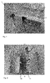
- Fig. 1 shows a distribution frame module 1 consisting of a first side wall 2, a bottom 3 and a second side wall 4.
- the second side wall 4 consists of an inner wall 5 and one outer wall 6.
- the cross sectional view of the second side wall may thus be shaped like a "U", turned upside down.
- Within the second side wall 4 an accommodation space for linear function 7 is formed inside the second side wall 4.
- the free space for linear function is in the range of 5 to 30 mm, preferably 10 to 20 mm, most preferably 15 mm.
- the distribution frame module 1 takes the general shape of a u-shaped box with an open front, back and top.
- the first side wall 2 is configured with a plurality of punch bridges 8 and a locking lever 9.
- the second side wall is configured with a plurality of guide holes 10 and a connecting edge 11.
- the punch bridges 8 are extending outwards from the first side wall, forming a female member 12.
- the punch bridge 8 is shaped to fit inside a guide hole 10.
- a guide hole 10 on the second side wall 4 contains a male member 13.
- the male member is preferably shaped as a capped triangle, to help guide the male member into the corresponding female member 12.
- Fig. 2 shows two distribution frame modules 1 aligned besides each other before assembly.
- the punch bridges 8 of one distribution frame module 1 corresponds to the guide holes 10 of the second distribution frame module 1.
- the punch bridges 8 of one distribution frame module 1 are placed inside the guide holes 10 of another distribution frame module 1, after which the male members 13 can be slid into the female members 12 with a sliding movement.
- the lever shape of the locking lever 9 together with its material properties will give the locking lever elastic properties.
- At the end of the locking lever is an edge protruding outwards from the first side wall 2.
- the distribution frame modules 1 can be manufactured from sheet metal, such as sheet aluminum or stainless steel.
- the thickness may be from 0.4 to 2 mm.
- the production method may be calendaring, rolling, cutting, pressing, punching, stamping, drilling, or a combination of these.
- the sheet metal material will both provide shielding properties for the distribution frame module 1, both for optical (light) and electrical (magnetic) applications.
- the sheet metal material will also provide the elastic properties of the locking lever 9.
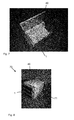
- Fig 3 shows a male wall plate 30, with a plurality of guide holes 31 and connecting edges 32.
- the wall plate allows a multitude of distribution frame modules 1 to connect to the male wall plate 30 through the punch bridges 8 and locking lever 9 located on the first side wall 2. Thus all the distribution frame modules 1 connected to the wall plate 30 will have the same orientation.
- Fig 4 shows a female wall plate 40, with a plurality of punch bridges 41 and locking levers 42.
- the wall plate allows a multitude of distribution frame modules 1 to connect to the female wall plate 40 through the guide holes 10 and connecting edges 11 located on the second side wall 4. Thus all the distribution frame modules 1 connected to the wall plate 40 will have the same orientation.
- Fig 5 shows an example of a complete optical distribution frame unit 50 wherein elements for handling optical fibers 51 are mounted on the distribution frame module 1.
- the elements for handling optical fibers 51 comprises elements for accommodating spliced joints between optical fibers 52 and/or patch connections between optical fibers 52 and/or optical splitters and/or wave division filters are mounted in the front of the distribution frame module 1 for easy access.
- the locking lever 9 is located in the front of the distribution frame module 1, allowing the user to snap in or remove the distribution frame module 1 from the front without use of any tools.
- Fig. 6 shows an example of three distribution frame modules 1 interconnected in an ODF 19" standard rack box 60.
- the distribution frame modules 1 will have the same orientation after being interconnected, allowing the user to reach the locking lever 9 of each distribution frame module 1 for easy snapping in and out a distribution frame unit 1 without use of any tools.
- Fig. 7 shows a modular combination of a distribution frame module 1 connected to a female wall plate 40.
- the the locking levers 42 of the female wall plate 40 are facing the user for easy snapping in and out a distribution frame unit 1 without use of any tools.
- Fig. 8 shows a modular combination 70 where three distribution frame modules 1 are connected to a female wall plate 40 and further shielded by a shield wall 71.
- the height of a distribution frame module 1 can be specified in a units (U) measure or rack unit (RU), where 1U (or 1RU) is 1.75 inches from top to bottom.
- U units
- RU rack unit
- the height of the distribution frame module 1 is in the range of 0.5 to 3 U, more preferable 1 to 2 U and most preferably 1 U.
- the height of the distribution frame module (1) is in the range of 20 to 135 mm, preferably 40 to 50 mm, while the width of the distribution frame module (1) is in the range of 100 to 500 mm, preferably 150 to 170 mm.
- the present invention has the advantage over the prior art that it provides a distribution frame module system with tool free snap on connection into several possible modular combinations, whereas known solutions requires time consuming fasteners during installation (small screws etc). Being a single piece sheet metal construction, it also provides significant advantages over prior module systems due to low cost production and few parts.
Landscapes
- Physics & Mathematics (AREA)
- General Physics & Mathematics (AREA)
- Optics & Photonics (AREA)
- Engineering & Computer Science (AREA)
- Computer Networks & Wireless Communication (AREA)
- Light Guides In General And Applications Therefor (AREA)
- Casings For Electric Apparatus (AREA)
Priority Applications (1)
| Application Number | Priority Date | Filing Date | Title |
|---|---|---|---|
| EP13306896.5A EP2889661B1 (de) | 2013-12-30 | 2013-12-30 | Verteilerrahmen |
Applications Claiming Priority (1)
| Application Number | Priority Date | Filing Date | Title |
|---|---|---|---|
| EP13306896.5A EP2889661B1 (de) | 2013-12-30 | 2013-12-30 | Verteilerrahmen |
Publications (2)
| Publication Number | Publication Date |
|---|---|
| EP2889661A1 true EP2889661A1 (de) | 2015-07-01 |
| EP2889661B1 EP2889661B1 (de) | 2019-10-02 |
Family
ID=49998032
Family Applications (1)
| Application Number | Title | Priority Date | Filing Date |
|---|---|---|---|
| EP13306896.5A Active EP2889661B1 (de) | 2013-12-30 | 2013-12-30 | Verteilerrahmen |
Country Status (1)
| Country | Link |
|---|---|
| EP (1) | EP2889661B1 (de) |
Citations (4)
| Publication number | Priority date | Publication date | Assignee | Title |
|---|---|---|---|---|
| US4497411A (en) * | 1982-04-19 | 1985-02-05 | Northern Telecom Limited | Distributing frame for telecommunications systems |
| EP2159613A2 (de) * | 2008-08-29 | 2010-03-03 | Corning Cable Systems LLC | Rückwärts verschiebbare Erweiterung in einem Glasfaserausrüstungstablett |
| WO2011130000A1 (en) * | 2010-04-16 | 2011-10-20 | Ccs Technology, Inc. | System comprising a plurality of distribution devices and distribution device |
| US20120294581A1 (en) * | 2011-05-18 | 2012-11-22 | Telect, Inc. | Adjustable Trough-Couplers |
-
2013
- 2013-12-30 EP EP13306896.5A patent/EP2889661B1/de active Active
Patent Citations (4)
| Publication number | Priority date | Publication date | Assignee | Title |
|---|---|---|---|---|
| US4497411A (en) * | 1982-04-19 | 1985-02-05 | Northern Telecom Limited | Distributing frame for telecommunications systems |
| EP2159613A2 (de) * | 2008-08-29 | 2010-03-03 | Corning Cable Systems LLC | Rückwärts verschiebbare Erweiterung in einem Glasfaserausrüstungstablett |
| WO2011130000A1 (en) * | 2010-04-16 | 2011-10-20 | Ccs Technology, Inc. | System comprising a plurality of distribution devices and distribution device |
| US20120294581A1 (en) * | 2011-05-18 | 2012-11-22 | Telect, Inc. | Adjustable Trough-Couplers |
Also Published As
| Publication number | Publication date |
|---|---|
| EP2889661B1 (de) | 2019-10-02 |
Similar Documents
| Publication | Publication Date | Title |
|---|---|---|
| US8687933B2 (en) | Field terminated fiber patch panel for rack and wall mounting | |
| EP1733462B1 (de) | Vertikal-kabel-manager | |
| EP2476261B1 (de) | Durchgangsrinne | |
| US8424827B2 (en) | Cable and box support plate | |
| CN102340942A (zh) | 服务器机柜 | |
| EP3048865A1 (de) | Schrank | |
| EP2738584A1 (de) | Glasfaserverteilungsvorrichtung | |
| US9516781B2 (en) | Fiber optic shelf with a removable roof panel | |
| US10187706B2 (en) | Snap clip fastener assembly | |
| EP2849550B1 (de) | Anpassungsvorrichtung für Kabelführungsarm | |
| US10485133B1 (en) | Fastening device | |
| EP2889661B1 (de) | Verteilerrahmen | |
| EP3062135A1 (de) | Faseroptischer abstreifer und kommunikationsvorrichtung | |
| US20140263868A1 (en) | Adjustable Trough-Couplers | |
| CN104160715A (zh) | 用于形成模块化配电板的系统以及用于组装所述模块化配电板的方法 | |
| CN208795771U (zh) | 一种电力通信信息接收器专用支架 | |
| CN214626220U (zh) | 通信信号机房综合布线固定装置 | |
| CN215816952U (zh) | 一种用于配电柜的卡固式安装盖板 | |
| CN205179570U (zh) | 用于通信设备的面板卡扣装置 | |
| US20070267563A1 (en) | Modular support structure for a medical device | |
| SE419684B (sv) | Anordning vid montering av en anslutningsplint i en kapa | |
| JP5767089B2 (ja) | 据付板 | |
| CN203734975U (zh) | 一种电气元件固定结构 | |
| EP2629129B1 (de) | Verteilungsvorrichtung | |
| JP2016201487A (ja) | 機器取付構造 |
Legal Events
| Date | Code | Title | Description |
|---|---|---|---|
| PUAI | Public reference made under article 153(3) epc to a published international application that has entered the european phase |
Free format text: ORIGINAL CODE: 0009012 |
|
| 17P | Request for examination filed |
Effective date: 20131230 |
|
| AK | Designated contracting states |
Kind code of ref document: A1 Designated state(s): AL AT BE BG CH CY CZ DE DK EE ES FI FR GB GR HR HU IE IS IT LI LT LU LV MC MK MT NL NO PL PT RO RS SE SI SK SM TR |
|
| AX | Request for extension of the european patent |
Extension state: BA ME |
|
| R17P | Request for examination filed (corrected) |
Effective date: 20160104 |
|
| RBV | Designated contracting states (corrected) |
Designated state(s): AL AT BE BG CH CY CZ DE DK EE ES FI FR GB GR HR HU IE IS IT LI LT LU LV MC MK MT NL NO PL PT RO RS SE SI SK SM TR |
|
| RAP1 | Party data changed (applicant data changed or rights of an application transferred) |
Owner name: NEXANS |
|
| GRAP | Despatch of communication of intention to grant a patent |
Free format text: ORIGINAL CODE: EPIDOSNIGR1 |
|
| STAA | Information on the status of an ep patent application or granted ep patent |
Free format text: STATUS: GRANT OF PATENT IS INTENDED |
|
| INTG | Intention to grant announced |
Effective date: 20190426 |
|
| GRAS | Grant fee paid |
Free format text: ORIGINAL CODE: EPIDOSNIGR3 |
|
| GRAA | (expected) grant |
Free format text: ORIGINAL CODE: 0009210 |
|
| STAA | Information on the status of an ep patent application or granted ep patent |
Free format text: STATUS: THE PATENT HAS BEEN GRANTED |
|
| AK | Designated contracting states |
Kind code of ref document: B1 Designated state(s): AL AT BE BG CH CY CZ DE DK EE ES FI FR GB GR HR HU IE IS IT LI LT LU LV MC MK MT NL NO PL PT RO RS SE SI SK SM TR |
|
| REG | Reference to a national code |
Ref country code: GB Ref legal event code: FG4D |
|
| REG | Reference to a national code |
Ref country code: CH Ref legal event code: EP Ref country code: AT Ref legal event code: REF Ref document number: 1186837 Country of ref document: AT Kind code of ref document: T Effective date: 20191015 |
|
| REG | Reference to a national code |
Ref country code: DE Ref legal event code: R096 Ref document number: 602013061201 Country of ref document: DE |
|
| REG | Reference to a national code |
Ref country code: IE Ref legal event code: FG4D |
|
| REG | Reference to a national code |
Ref country code: SE Ref legal event code: TRGR |
|
| REG | Reference to a national code |
Ref country code: NL Ref legal event code: MP Effective date: 20191002 |
|
| REG | Reference to a national code |
Ref country code: NO Ref legal event code: T2 Effective date: 20191002 |
|
| REG | Reference to a national code |
Ref country code: LT Ref legal event code: MG4D |
|
| REG | Reference to a national code |
Ref country code: AT Ref legal event code: MK05 Ref document number: 1186837 Country of ref document: AT Kind code of ref document: T Effective date: 20191002 |
|
| PG25 | Lapsed in a contracting state [announced via postgrant information from national office to epo] |
Ref country code: ES Free format text: LAPSE BECAUSE OF FAILURE TO SUBMIT A TRANSLATION OF THE DESCRIPTION OR TO PAY THE FEE WITHIN THE PRESCRIBED TIME-LIMIT Effective date: 20191002 Ref country code: LV Free format text: LAPSE BECAUSE OF FAILURE TO SUBMIT A TRANSLATION OF THE DESCRIPTION OR TO PAY THE FEE WITHIN THE PRESCRIBED TIME-LIMIT Effective date: 20191002 Ref country code: PL Free format text: LAPSE BECAUSE OF FAILURE TO SUBMIT A TRANSLATION OF THE DESCRIPTION OR TO PAY THE FEE WITHIN THE PRESCRIBED TIME-LIMIT Effective date: 20191002 Ref country code: GR Free format text: LAPSE BECAUSE OF FAILURE TO SUBMIT A TRANSLATION OF THE DESCRIPTION OR TO PAY THE FEE WITHIN THE PRESCRIBED TIME-LIMIT Effective date: 20200103 Ref country code: BG Free format text: LAPSE BECAUSE OF FAILURE TO SUBMIT A TRANSLATION OF THE DESCRIPTION OR TO PAY THE FEE WITHIN THE PRESCRIBED TIME-LIMIT Effective date: 20200102 Ref country code: LT Free format text: LAPSE BECAUSE OF FAILURE TO SUBMIT A TRANSLATION OF THE DESCRIPTION OR TO PAY THE FEE WITHIN THE PRESCRIBED TIME-LIMIT Effective date: 20191002 Ref country code: PT Free format text: LAPSE BECAUSE OF FAILURE TO SUBMIT A TRANSLATION OF THE DESCRIPTION OR TO PAY THE FEE WITHIN THE PRESCRIBED TIME-LIMIT Effective date: 20200203 Ref country code: FI Free format text: LAPSE BECAUSE OF FAILURE TO SUBMIT A TRANSLATION OF THE DESCRIPTION OR TO PAY THE FEE WITHIN THE PRESCRIBED TIME-LIMIT Effective date: 20191002 Ref country code: NL Free format text: LAPSE BECAUSE OF FAILURE TO SUBMIT A TRANSLATION OF THE DESCRIPTION OR TO PAY THE FEE WITHIN THE PRESCRIBED TIME-LIMIT Effective date: 20191002 Ref country code: AT Free format text: LAPSE BECAUSE OF FAILURE TO SUBMIT A TRANSLATION OF THE DESCRIPTION OR TO PAY THE FEE WITHIN THE PRESCRIBED TIME-LIMIT Effective date: 20191002 |
|
| PG25 | Lapsed in a contracting state [announced via postgrant information from national office to epo] |
Ref country code: RS Free format text: LAPSE BECAUSE OF FAILURE TO SUBMIT A TRANSLATION OF THE DESCRIPTION OR TO PAY THE FEE WITHIN THE PRESCRIBED TIME-LIMIT Effective date: 20191002 Ref country code: CZ Free format text: LAPSE BECAUSE OF FAILURE TO SUBMIT A TRANSLATION OF THE DESCRIPTION OR TO PAY THE FEE WITHIN THE PRESCRIBED TIME-LIMIT Effective date: 20191002 Ref country code: IS Free format text: LAPSE BECAUSE OF FAILURE TO SUBMIT A TRANSLATION OF THE DESCRIPTION OR TO PAY THE FEE WITHIN THE PRESCRIBED TIME-LIMIT Effective date: 20200224 Ref country code: HR Free format text: LAPSE BECAUSE OF FAILURE TO SUBMIT A TRANSLATION OF THE DESCRIPTION OR TO PAY THE FEE WITHIN THE PRESCRIBED TIME-LIMIT Effective date: 20191002 |
|
| PG25 | Lapsed in a contracting state [announced via postgrant information from national office to epo] |
Ref country code: AL Free format text: LAPSE BECAUSE OF FAILURE TO SUBMIT A TRANSLATION OF THE DESCRIPTION OR TO PAY THE FEE WITHIN THE PRESCRIBED TIME-LIMIT Effective date: 20191002 |
|
| REG | Reference to a national code |
Ref country code: DE Ref legal event code: R119 Ref document number: 602013061201 Country of ref document: DE |
|
| PG2D | Information on lapse in contracting state deleted |
Ref country code: IS |
|
| PG25 | Lapsed in a contracting state [announced via postgrant information from national office to epo] |
Ref country code: RO Free format text: LAPSE BECAUSE OF FAILURE TO SUBMIT A TRANSLATION OF THE DESCRIPTION OR TO PAY THE FEE WITHIN THE PRESCRIBED TIME-LIMIT Effective date: 20191002 Ref country code: EE Free format text: LAPSE BECAUSE OF FAILURE TO SUBMIT A TRANSLATION OF THE DESCRIPTION OR TO PAY THE FEE WITHIN THE PRESCRIBED TIME-LIMIT Effective date: 20191002 Ref country code: DK Free format text: LAPSE BECAUSE OF FAILURE TO SUBMIT A TRANSLATION OF THE DESCRIPTION OR TO PAY THE FEE WITHIN THE PRESCRIBED TIME-LIMIT Effective date: 20191002 Ref country code: IS Free format text: LAPSE BECAUSE OF FAILURE TO SUBMIT A TRANSLATION OF THE DESCRIPTION OR TO PAY THE FEE WITHIN THE PRESCRIBED TIME-LIMIT Effective date: 20200202 |
|
| REG | Reference to a national code |
Ref country code: CH Ref legal event code: PL |
|
| PLBE | No opposition filed within time limit |
Free format text: ORIGINAL CODE: 0009261 |
|
| STAA | Information on the status of an ep patent application or granted ep patent |
Free format text: STATUS: NO OPPOSITION FILED WITHIN TIME LIMIT |
|
| REG | Reference to a national code |
Ref country code: BE Ref legal event code: MM Effective date: 20191231 |
|
| PG25 | Lapsed in a contracting state [announced via postgrant information from national office to epo] |
Ref country code: SM Free format text: LAPSE BECAUSE OF FAILURE TO SUBMIT A TRANSLATION OF THE DESCRIPTION OR TO PAY THE FEE WITHIN THE PRESCRIBED TIME-LIMIT Effective date: 20191002 Ref country code: SK Free format text: LAPSE BECAUSE OF FAILURE TO SUBMIT A TRANSLATION OF THE DESCRIPTION OR TO PAY THE FEE WITHIN THE PRESCRIBED TIME-LIMIT Effective date: 20191002 Ref country code: IT Free format text: LAPSE BECAUSE OF FAILURE TO SUBMIT A TRANSLATION OF THE DESCRIPTION OR TO PAY THE FEE WITHIN THE PRESCRIBED TIME-LIMIT Effective date: 20191002 Ref country code: MC Free format text: LAPSE BECAUSE OF FAILURE TO SUBMIT A TRANSLATION OF THE DESCRIPTION OR TO PAY THE FEE WITHIN THE PRESCRIBED TIME-LIMIT Effective date: 20191002 |
|
| 26N | No opposition filed |
Effective date: 20200703 |
|
| GBPC | Gb: european patent ceased through non-payment of renewal fee |
Effective date: 20200102 |
|
| PG25 | Lapsed in a contracting state [announced via postgrant information from national office to epo] |
Ref country code: FR Free format text: LAPSE BECAUSE OF NON-PAYMENT OF DUE FEES Effective date: 20191231 Ref country code: LU Free format text: LAPSE BECAUSE OF NON-PAYMENT OF DUE FEES Effective date: 20191230 Ref country code: IE Free format text: LAPSE BECAUSE OF NON-PAYMENT OF DUE FEES Effective date: 20191230 Ref country code: GB Free format text: LAPSE BECAUSE OF NON-PAYMENT OF DUE FEES Effective date: 20200102 Ref country code: DE Free format text: LAPSE BECAUSE OF NON-PAYMENT OF DUE FEES Effective date: 20200701 |
|
| PG25 | Lapsed in a contracting state [announced via postgrant information from national office to epo] |
Ref country code: SI Free format text: LAPSE BECAUSE OF FAILURE TO SUBMIT A TRANSLATION OF THE DESCRIPTION OR TO PAY THE FEE WITHIN THE PRESCRIBED TIME-LIMIT Effective date: 20191002 Ref country code: BE Free format text: LAPSE BECAUSE OF NON-PAYMENT OF DUE FEES Effective date: 20191231 Ref country code: CH Free format text: LAPSE BECAUSE OF NON-PAYMENT OF DUE FEES Effective date: 20191231 Ref country code: LI Free format text: LAPSE BECAUSE OF NON-PAYMENT OF DUE FEES Effective date: 20191231 |
|
| PG25 | Lapsed in a contracting state [announced via postgrant information from national office to epo] |
Ref country code: CY Free format text: LAPSE BECAUSE OF FAILURE TO SUBMIT A TRANSLATION OF THE DESCRIPTION OR TO PAY THE FEE WITHIN THE PRESCRIBED TIME-LIMIT Effective date: 20191002 |
|
| PG25 | Lapsed in a contracting state [announced via postgrant information from national office to epo] |
Ref country code: HU Free format text: LAPSE BECAUSE OF FAILURE TO SUBMIT A TRANSLATION OF THE DESCRIPTION OR TO PAY THE FEE WITHIN THE PRESCRIBED TIME-LIMIT; INVALID AB INITIO Effective date: 20131230 Ref country code: MT Free format text: LAPSE BECAUSE OF FAILURE TO SUBMIT A TRANSLATION OF THE DESCRIPTION OR TO PAY THE FEE WITHIN THE PRESCRIBED TIME-LIMIT Effective date: 20191002 |
|
| PG25 | Lapsed in a contracting state [announced via postgrant information from national office to epo] |
Ref country code: TR Free format text: LAPSE BECAUSE OF FAILURE TO SUBMIT A TRANSLATION OF THE DESCRIPTION OR TO PAY THE FEE WITHIN THE PRESCRIBED TIME-LIMIT Effective date: 20191002 |
|
| PG25 | Lapsed in a contracting state [announced via postgrant information from national office to epo] |
Ref country code: MK Free format text: LAPSE BECAUSE OF FAILURE TO SUBMIT A TRANSLATION OF THE DESCRIPTION OR TO PAY THE FEE WITHIN THE PRESCRIBED TIME-LIMIT Effective date: 20191002 |
|
| PGFP | Annual fee paid to national office [announced via postgrant information from national office to epo] |
Ref country code: SE Payment date: 20231220 Year of fee payment: 11 Ref country code: NO Payment date: 20231222 Year of fee payment: 11 |