EP2889402A1 - Inner cylindrical body of drafting roller, roller member of drafting roller, drafting roller, drafting device, and air-jet spinning machine - Google Patents
Inner cylindrical body of drafting roller, roller member of drafting roller, drafting roller, drafting device, and air-jet spinning machine Download PDFInfo
- Publication number
- EP2889402A1 EP2889402A1 EP14195447.9A EP14195447A EP2889402A1 EP 2889402 A1 EP2889402 A1 EP 2889402A1 EP 14195447 A EP14195447 A EP 14195447A EP 2889402 A1 EP2889402 A1 EP 2889402A1
- Authority
- EP
- European Patent Office
- Prior art keywords
- cylindrical body
- roller
- drafting
- coating
- inner cylindrical
- Prior art date
- Legal status (The legal status is an assumption and is not a legal conclusion. Google has not performed a legal analysis and makes no representation as to the accuracy of the status listed.)
- Withdrawn
Links
- 238000010042 air jet spinning Methods 0.000 title claims description 14
- 239000011248 coating agent Substances 0.000 claims abstract description 103
- 238000000576 coating method Methods 0.000 claims abstract description 101
- 230000002093 peripheral effect Effects 0.000 claims abstract description 87
- 238000004804 winding Methods 0.000 claims description 18
- 229910052751 metal Inorganic materials 0.000 claims description 16
- 239000002184 metal Substances 0.000 claims description 16
- 239000000835 fiber Substances 0.000 claims description 13
- 239000000463 material Substances 0.000 claims description 12
- OKTJSMMVPCPJKN-UHFFFAOYSA-N Carbon Chemical compound [C] OKTJSMMVPCPJKN-UHFFFAOYSA-N 0.000 claims description 8
- 150000002222 fluorine compounds Chemical class 0.000 claims description 8
- 229910002804 graphite Inorganic materials 0.000 claims description 8
- 239000010439 graphite Substances 0.000 claims description 8
- CWQXQMHSOZUFJS-UHFFFAOYSA-N molybdenum disulfide Chemical compound S=[Mo]=S CWQXQMHSOZUFJS-UHFFFAOYSA-N 0.000 claims description 8
- 229910052982 molybdenum disulfide Inorganic materials 0.000 claims description 8
- 238000009987 spinning Methods 0.000 description 32
- 125000006850 spacer group Chemical group 0.000 description 13
- 238000011176 pooling Methods 0.000 description 11
- 239000000314 lubricant Substances 0.000 description 7
- 230000002265 prevention Effects 0.000 description 7
- 238000005304 joining Methods 0.000 description 6
- 238000011144 upstream manufacturing Methods 0.000 description 6
- 239000007787 solid Substances 0.000 description 5
- 230000007547 defect Effects 0.000 description 3
- 239000002932 luster Substances 0.000 description 3
- 230000003287 optical effect Effects 0.000 description 3
- 238000001514 detection method Methods 0.000 description 2
- 239000004519 grease Substances 0.000 description 2
- 238000000034 method Methods 0.000 description 2
- 229910000975 Carbon steel Inorganic materials 0.000 description 1
- 230000002159 abnormal effect Effects 0.000 description 1
- 230000002411 adverse Effects 0.000 description 1
- 239000004411 aluminium Substances 0.000 description 1
- 229910052782 aluminium Inorganic materials 0.000 description 1
- XAGFODPZIPBFFR-UHFFFAOYSA-N aluminium Chemical compound [Al] XAGFODPZIPBFFR-UHFFFAOYSA-N 0.000 description 1
- 230000003139 buffering effect Effects 0.000 description 1
- 239000010962 carbon steel Substances 0.000 description 1
- 230000006835 compression Effects 0.000 description 1
- 238000007906 compression Methods 0.000 description 1
- 238000010276 construction Methods 0.000 description 1
- 238000007598 dipping method Methods 0.000 description 1
- 238000005516 engineering process Methods 0.000 description 1
- 238000004519 manufacturing process Methods 0.000 description 1
- 238000012986 modification Methods 0.000 description 1
- 230000004048 modification Effects 0.000 description 1
- 230000009972 noncorrosive effect Effects 0.000 description 1
- 238000007789 sealing Methods 0.000 description 1
- 238000005507 spraying Methods 0.000 description 1
- 239000000126 substance Substances 0.000 description 1
- 239000002699 waste material Substances 0.000 description 1
Images


Classifications
-
- D—TEXTILES; PAPER
- D01—NATURAL OR MAN-MADE THREADS OR FIBRES; SPINNING
- D01H—SPINNING OR TWISTING
- D01H5/00—Drafting machines or arrangements ; Threading of roving into drafting machine
- D01H5/18—Drafting machines or arrangements without fallers or like pinned bars
- D01H5/70—Constructional features of drafting elements
- D01H5/74—Rollers or roller bearings
-
- D—TEXTILES; PAPER
- D01—NATURAL OR MAN-MADE THREADS OR FIBRES; SPINNING
- D01H—SPINNING OR TWISTING
- D01H4/00—Open-end spinning machines or arrangements for imparting twist to independently moving fibres separated from slivers; Piecing arrangements therefor; Covering endless core threads with fibres by open-end spinning techniques
- D01H4/30—Arrangements for separating slivers into fibres; Orienting or straightening fibres, e.g. using guide-rolls
Definitions
- the present invention mainly relates to a configuration of a drafting roller for use in a drafting device of a spinning machine.
- a typical spinning machine includes a drafting device that stretches a sliver, which serves as a base material of a yarn, until the sliver reaches a state that is appropriate for spinning.
- a drafting device includes plural drafting rollers.
- the sliver is nipped between the rotating drafting rollers and stretched until a fiber bundle of a predetermined thickness is formed.
- the drafting roller includes a cylindrical roller member and a shaft member (arbor).
- a bearing that rotatably supports the roller member is mounted on the shaft member.
- An outer peripheral surface of the roller member of the drafting roller is made of rubber, and a metal cylindrical body (sleeve) is arranged on an inner periphery of the roller member.
- Such a structure is disclosed, for example, in Japanese Patent Application Laid-open No. H11-247036 .
- bearings bearings (bearings 20 and 21) are arranged between a cylindrical body of the roller member (roller cylindrical body 12) and a shaft member (shaft 10). The cylindrical body of the roller member is fitted onto the bearings and thereby, the roller member is supported to be rotatable relative to the shaft member.
- roller member The rubber on the outer peripheral surface of the roller member tends to wear out with use. Hence, it is preferable that the roller member is easy to replace. To achieve this, in the conventional drafting roller, a small gap is secured between the cylindrical body of the roller member and the bearings. In this structure, the worn out roller member can be easily pulled out and removed from the bearings, and a new roller member (unworn) can then be easily fitted by inserting the roller member onto the bearings.
- An inner cylindrical body according to an aspect of the present invention is arranged in a drafting roller inside an outer cylindrical body of a roller member that is rotatably supported via a bearing, and the outer cylindrical body is made of rubber.
- a coating is applied on at least a portion of an inner peripheral surface of the inner cylindrical body.
- a roller member according to another aspect of the present invention includes the above inner cylindrical body, and an outer cylindrical body that is made of rubber and that is arranged outside the inner cylindrical body.
- a drafting roller according to still another aspect of the present invention includes the above roller member, and an arbor that includes a bearing that freely rotatably supports the roller member.
- a drafting roller includes a cylindrical roller member and an arbor that rotatably supports the roller member.
- a coating is applied on at least the portion of the outer peripheral surface of the arbor.
- a drafting device includes a roller pair constituted by the above drafting roller and a roller arranged opposing the drafting roller.
- An air-jet spinning machine includes the above drafting device, an air-jet spinning device that twists the fiber bundle supplied from the drafting device by the action of a swirling air current to form a spun yarn, and a winding device that winds the spun yarn.
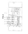
- a spinning frame 1 that is a spinning machine includes plural spinning units 2 arranged side by side and a yarn joining carrier 3.
- each of the spinning units 2 includes, arranged sequentially from upstream to downstream, a drafting device 7, a spinning device (spinning section) 9, a yarn pooling device 12, and a winding device 13.
- upstream and downstream refer to upstream and downstream in a running direction of a fiber bundle and a yarn during spinning.
- the spinning device 9 of each of the spinning units 2 spins a fiber bundle 8 conveyed from the drafting device 7 to form a spun yarn 10.
- the spun yarn 10 is wound by the winding device 13 to form a package 45.
- the drafting device 7 is arranged near an upper edge of the spinning frame 1.
- the drafting device 7 includes plural drafting rollers 16, 17, 19, 20, 66, 67, 69, and 70.
- the drafting rollers 66, 67, 69, and 70 are made of metal and are called bottom rollers. Each of the bottom rollers 66, 67, 69, and 70 is driven to rotate about an axis thereof by a not shown driving source.
- the drafting device 7 according to the present embodiment includes four bottom rollers, which are, sequentially from upstream, a back bottom roller 66, a third bottom roller 67, a middle bottom roller 69 with a rubber apron belt 68 stretched thereon, and a front bottom roller 70.
- the drafting rollers 16, 17, 19, and 20 are called top rollers.
- the drafting device 7 according to the present embodiment includes four top rollers, which are, sequentially from upstream, a back top roller 16, a third top roller 17, a middle top roller 19 with an apron belt 18 stretched thereon, and a front top roller 20.
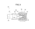
- FIG. 3 is a drawing of a structure of the front top roller 20.
- the structures of the other top rollers 16, 17, and 19 are identical to that of the front top roller 20.
- the top roller 20 includes a cylindrical roller member 26 and an arbor (shaft member) 27.
- the outer peripheral surface of the roller member 26 is made of rubber.
- a bearing member 28 that rotatably supports the roller member 26 is mounted on the arbor 27.
- the drafting device 7 is configured as a so-called four-line drafting device that includes four drafting roller pairs, namely, a back roller pair constituted by the drafting rollers 16 and 66, a third roller pair constituted by the drafting rollers 17 and 67, a middle roller pair constituted by the drafting rollers 19 and 69, and a front roller pair constituted by the drafting rollers 20 and 70.
- the top roller and the bottom roller of each of the drafting roller pairs are arranged opposite to each other.
- Each of the top rollers 16, 17, 19, and 20 is arranged more to the front of the device than their respective opposing bottom rollers 66, 67, 69, and 70.
- the drafting device 7 further includes a not shown urging member that urges each of the top rollers 16, 17, 19, and 20 toward their respective opposing bottom rollers 66, 67, 69, and 70.
- the outer peripheral surface of the roller member 26 of each of the top rollers 16, 17, 19, and 20 is pressed against the outer peripheral surface of each of the bottom rollers 66, 67, 69, and 70, respectively.
- the rotating drafting roller pairs nip a sliver 15 therebetween and convey it downstream.
- the rotational speed of each drafting roller pair is higher than the rotational speed of the adjacent drafting roller pair upstream thereof.
- the sliver 15 is stretched while being conveyed by the drafting roller pairs, and converted into the fiber bundle 8 having a predetermined width.
- the spinning device 9 is arranged immediately downstream of the front roller pair.
- the fiber bundle 8 is supplied from the drafting device 7 to the spinning device 9.
- the spinning device 9 twists the fiber bundle 8 supplied from the drafting device 7 to create the spun yarn 10.
- an air-jet spinning device that twists the fiber bundle 8 by using a swirling air current has been used.
- the winding device 13 is arranged downstream of the spinning device 9.
- the winding device 13 includes a cradle arm 71 that is supported to be swingable about a shaft 73.
- the cradle arm 71 rotatably supports a bobbin 48 onto which the spun yarn 10 is wound.
- the winding device 13 includes a winding drum 72 and a traverse device 75.
- the winding drum 72 is driven while being in contact with the outer peripheral surface of the bobbin 48 or the outer peripheral surface of the package 45 that is formed by winding the spun yarn 10 onto an outer peripheral surface of the bobbin 48.
- the traverse device 75 includes a traverse guide 76 that is engageable with the spun yarn 10.
- the yarn pooling device 12 is arranged between the spinning device 9 and the winding device 13. As shown in FIG. 2 , the yarn pooling device 12 includes a yarn pooling roller 14 and an electric motor 25 that drives the yarn pooling roller 14 to rotate.
- a certain amount of the spun yarn 10 can be wound on an outer peripheral surface of the yarn pooling roller 14 to temporarily pool the yarn. Because the spun yarn 10 can be temporarily pooled in the yarn pooling device 12, the yarn pooling device 12 can be made to function as a kind of a buffer. The buffering function of the yarn pooling device 12 prevents troubles (for example, slackening of the spun yarn 10) that can occur because of a mismatch in a spinning speed of the spinning device 9 and a winding speed of the winding device 13 due to some reason.
- a yarn clearer (yarn quality measuring device) 52 is arranged between the spinning device 9 and the yarn pooling device 12.
- the spun yarn 10 that is spun in the spinning device 9 passes through the yarn clearer 52 before being wound in the yarn pooling device 12.
- the yarn clearer 52 monitors the running spun yarn 10 with a not shown optical sensor.
- the optical sensor detects a yarn defect (a portion of the spun yarn 10 having an abnormal thickness) in the spun yarn 10
- the yarn clearer 52 transmits a yarn defect detection signal to a not shown unit controller.
- the sensor of the yarn clearer 52 is not limited to the optical sensor; it can be an electrostatic capacitive sensor.
- the yarn clearer 52 can also detect foreign substance included in the spun yarn 10 as a yarn defect.
- the yarn joining carrier 3 includes a splicer (yarn joining device) 43 and yarn catching members 44 and 46.
- a splicer yarn joining device
- yarn catching members 44 and 46 When yarn cut or yarn breakage occurs in a certain spinning unit 2, the yarn joining carrier 3 travels up to that spinning unit 2. Then, the yarn joining carrier 3 catches the cut ends of the spun yarn 10 by using the yarn catching members 44 and 46 and guides the yarn ends to the splicer 43.
- the splicer 43 joins the guided yarn ends together (yarn joining).
- the front top roller 20 of the drafting device 7 is explained below in detail.
- the front top roller 20 includes the roller member 26 and the arbor 27.
- the arbor 27 includes a shaft member 29 and a bearing member 28.
- the bearing member 28 is arranged at the end of the shaft member 29.
- the bearing member 28 is arranged at each end of the arbor 27. That is, the arbor 27 includes two bearing members 28. Only one bearing member 28, however, is shown in FIGS. 3 and 4 .
- the bearing member 28 includes two bearings 30 and 31 and a spacer 32.
- Each of the bearings 30 and 31 has a known configuration in which a rotating body is arranged between an outer ring and an inner ring.
- the outer ring, the inner ring, and the rotating body of each of the bearings 30 and 31 are made of metal.
- the spacer 32 is arranged between the outer ring of the bearing 30 and the outer ring of the bearing 31.
- a washer 33 is fixed to an end face of the shaft member 29 with a bolt 51.
- a pressure receiving surface 34 that opposes the washer 33 is formed in the shaft member 29.
- the inner ring of the bearing 30 and the inner ring of the bearing 31 are arranged between the pressure receiving surface 34 and the washer 33.
- An urging member 35 (concretely, a compression coil spring) is arranged between the inner ring of the bearing 30 and the inner ring of the bearing 31.
- the spacer 32 is a substantially cylindrical member made of metal.
- An outer diameter of the spacer 32 is substantially identical to outer diameters of the outer rings of the bearings 30 and 31.
- the outer peripheral surface of the outer ring of the bearing 30, the outer peripheral surface of the outer ring of the bearing 31 and the outer peripheral surface of the spacer 32 are substantially flush with each other. Accordingly, the outer peripheral surface of the outer ring of the bearing 30, the outer peripheral surface of the outer ring of the bearing 31 and the outer peripheral surface of the spacer 32 are together referred to as an "outer peripheral surface of the bearing member 28".
- the outer peripheral surface of the bearing member 28 can be said to be made of metal.
- the outer peripheral surface of the bearing member 28 has no coating (later-explained).
- the spacer 32 rotates integrally with the outer ring of the bearing 30 and the outer ring of the bearing 31.
- a C ring 37 is fitted onto the outer periphery of the spacer 32.
- the roller member 26 is overall cylindrical and is constituted by plural concentric layers. As shown in FIG. 4 , the roller member 26 according to the present embodiment includes, sequentially from outer periphery, an outer cylindrical body 38, an intermediate cylindrical body 39, and an inner cylindrical body 40.
- the outer cylindrical body 38 is made of rubber and is substantially cylindrical.
- the outer cylindrical body 38 is directly in contact with the sliver 15.
- the inner cylindrical body 40 is arranged on the inner periphery of the outer cylindrical body 38.
- the inner cylindrical body 40 is made of metal (in the present embodiment, carbon steel for machine structure) and is substantially cylindrical.
- the inner cylindrical body 40 is longer (the length in its axial direction) than the outer cylindrical body 38. Accordingly, the inner cylindrical body 40 includes a part that is located on the inner periphery of the outer cylindrical body 38 and a part that projects along the axial direction from the end face of the outer cylindrical body 38. As shown in FIG. 4 , the part of the inner cylindrical body 40 that is located on the inner periphery of the outer cylindrical body 38 is called an inner peripheral portion 41 and the part of the inner cylindrical body 40 that projects along the axial direction from the end face of the outer cylindrical body 38 is called a projecting portion 42. Furthermore, as shown in FIG. 3 , the roller member 26 is arranged such that the projecting portion 42 projects towards the side opposite to the end face of the shaft member 29.
- a substantially cylindrical intermediate cylindrical body 39 is arranged between the inner peripheral portion 41 of the inner cylindrical body 40 and the outer cylindrical body 38.
- the intermediate cylindrical body 39 is made of metal (in the present embodiment, the metal is aluminium) and is substantially cylindrical.
- the intermediate cylindrical body 39 is bonded to the inner peripheral surface of the outer cylindrical body 38 in an appropriate manner. Furthermore, the intermediate cylindrical body 39 is fitted onto the outer peripheral surface of the inner peripheral portion 41 of the inner cylindrical body 40.
- cylindrical or “cylindrical body” is not limited to a cylindrical shape with a perfect circular cross-section but also includes a wide range of rotor-shaped bodies having an inner peripheral surface and an outer peripheral surface. Accordingly, even if steps and/or grooves are formed on the outer peripheral surface and/or the inner peripheral surface of the outer cylindrical body 38 or the intermediate cylindrical body 39 or the inner cylindrical body 40, they would still be referred to as “cylindrical” or “cylindrical body”. For example, as shown in FIG. 4 , steps are formed on the outer peripheral surface of the outer cylindrical body 38 according to the present embodiment.
- the bearing member 28 is arranged on the inner periphery of the inner peripheral portion 41 of the inner cylindrical body 40.
- the outer peripheral surface of the bearing member 28 almost touches the inner peripheral surface of the inner peripheral portion 41 of the inner cylindrical body 40.
- a small gap is secured between the outer peripheral surface of the bearing member 28 and the inner peripheral surface of the inner cylindrical body 40. This gap allows the roller member 26 to be easily removed from and fitted onto the bearing member 28 (indicated by the bold arrow in FIG. 4 ).
- a positioning groove 47 is formed on the inner peripheral surface of the inner peripheral portion 41.
- the C ring 37 of the bearing member 28 is fitted into the positioning groove 47.
- the roller member 26 is positioned relative to the bearing member 28 along the axial direction (the state shown in FIG. 3 ).
- a cap 49 that covers an end face portion of the front top roller 20 is fitted onto the roller member 26.
- An O ring 50 is arranged on the outer periphery of the shaft member 29 on the inner side of the projecting portion 42 of the inner cylindrical body 40. The cap 49 and the O ring 50 prevent yarn waste, and the like, from entering the bearing member 28.
- a coating 53 is applied on the inner peripheral surface of the inner cylindrical body 40 of the roller member 26 according to the present embodiment.
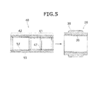
- the portions where the coating 53 is applied are indicated by the bold dotted lines.
- a material that is slippery (having low resistance) is used for the coating 53. Accordingly, the portion where the coating 53 is applied has a relatively lower coefficient of friction than the inner peripheral surface of the inner cylindrical body 40 prior to the application of the coating 53.
- the type of the coating 53 is not particularly limited.
- a film of solid lubricant dry coating film lubricant that has excellent lubricity, such as molybdenum disulfide, graphite, fluorine compounds, and the like, can be used as the coating 53.
- the portion where the coating 53 is applied has a different color than the original color (metallic luster) of the inner cylindrical body 40.
- the coated portion looks black when molybdenum disulfide or graphite is used and looks white or orange when a fluorine compound is used.
- the coated portion can be easily differentiated visually from the non-coated portion. This allows easy detection of any peeling of the coating 53.
- the method of application of the coating 53 on the inner cylindrical body 40 is not particularly limited. Known methods such as spraying and/or dipping can be used to apply the coating.
- the two metal layers (the inner cylindrical body 40 and the bearing member 28) can be prevented from coming into direct contact, and the friction between the inner cylindrical body 40 and the bearing member 28 can be reduced. With this structure, fretting between the inner cylindrical body 40 and the bearing member 28 can be prevented.
- the coating 53 can be applied on the portion of the inner cylindrical body 40 that comes into contact with the bearing member 28 during rotation.
- the coating 53 can be applied only on the inner peripheral surface of the inner peripheral portion 41 of the inner cylindrical body 40. That is, the coating 53 need not be applied on the inner peripheral surface of the projecting portion 42 of the inner cylindrical body 40. By applying the coating only on the required portion, coating material can be saved.
- the coating 53 is applied on the inner peripheral surface of the projecting portion 42 of the inner cylindrical body 40. Even though the coating 53 on this portion does not have a bearing on the prevention of fretting, it can be expected to be effective in improving the ease of replaceability of the roller member 26. That is, when the roller member 26 is fitted onto the bearing member 28, as indicated by the bold double-headed arrow in FIG. 4 , the bearing member 28 is inserted inside the inner cylindrical body 40 from the projecting portion 42 side of the inner cylindrical body 40. Accordingly, if the coating 53 is also applied on the inner peripheral surface of the projecting portion 42 of the inner cylindrical body 40 as it is done in the present embodiment, the bearing member 28 can be easily inserted into the inner cylindrical body 40.
- a technology related to coating in the field of drafting rollers is disclosed, for example, in Japanese Translation of PCT International Publication for Patent Application No. 2012-508828 .
- this patent document discloses a top roller with a coating in the form of a non-abrasive non-corrosive member applied on a shaft body (middle shaft member 2).
- the coating disclosed in this patent document is not applied on the portion that is in contact with a rotating roller member (in the first place, it is not mentioned in that application that the roller member is replaceable). Accordingly, the coating mentioned in this patent document has no relevance to prevention of fretting.
- the inner cylindrical body 40 of the front top roller 20 is more expensive than the conventional inner cylindrical body (that is devoid of coating). Consequently, if the inner cylindrical body 40 can be reused when replacing the roller member 26, it would be advantageous from cost perspective. If, during replacement, the outer cylindrical body 38 (and the intermediate cylindrical body 39 that is bonded to the outer cylindrical body 38) that is worn out due to use can be removed from the inner cylindrical body 40, the inner cylindrical body 40 can be reused.
- the coating 53 is also applied on the outer peripheral surface of the inner cylindrical body 40. Consequently, a frictional resistance between the inner cylindrical body 40 and the intermediate cylindrical body 39 fitted onto the outside of the inner cylindrical body 40 is reduced. Accordingly, the intermediate cylindrical body 39 (and the outer cylindrical body 38 bonded to the intermediate cylindrical body 39) can be easily removed from the inner cylindrical body 40 (as indicated by the bold arrow in FIG. 5 ). Consequently, the inner cylindrical body 40 can be reused, and thereby a replacement cost of the roller member 26 can be reduced.
- the coating 53 is applied on both the inner peripheral surface and the outer peripheral surface of the inner cylindrical body 40. Consequently, multiple advantages, namely, prevention of fretting, easy replaceability of the roller member 26, reuse of the inner cylindrical body 40, and the resulting replacement cost reduction, can be gained. Furthermore, because the coating 53 is applied on the entire inner cylindrical body 40, there is no need to apply a mask during the coating operation. Consequently, the coating operation can be easily performed and a manufacturing cost of the inner cylindrical body 40 can be reduced.
- the coating 53 is applied on the inner peripheral surface of the inner cylindrical body 40 according to the present embodiment.
- the coating 53 is applied on the inner peripheral surface of the inner cylindrical body 40, fretting between the inner cylindrical body 40 and the bearing member 28 can be prevented.
- the portion where the coating 53 is applied has less coefficient of friction than the inner peripheral surface of the inner cylindrical body 40 devoid of the coating 53.
- the inner cylindrical body 40 is made of metal and the coating 53 is non-metallic. Consequently, the portion where the coating 53 is applied has a different color than the original color (metallic luster) of the inner cylindrical body 40. Accordingly, any peeling of the coating 53 can be easily confirmed visually.
- the material of the coating 53 of the inner cylindrical body 40 is at least any one of molybdenum disulfide, graphite, and fluorine compounds. Because the coating 53 of any of the above coating agents is slippery and durable, fretting between the inner cylindrical body 40 and the bearing member 28 can be reliably prevented.
- the coating 53 is also applied on the outer peripheral surface of the inner cylindrical body 40. Consequently, the outer cylindrical body 38 (and the intermediate cylindrical body 39 bonded to the outer cylindrical body 38) can be easily removed from the inner cylindrical body 40. Consequently, the inner cylindrical body 40 can be reused. Furthermore, because the coating 53 is applied on the entire inner cylindrical body 40, there is no need to apply a mask, and the like, during the coating operation. Consequently, the coating operation can be simplified.
- the roller member 26 includes the inner cylindrical body 40, and the outer cylindrical body 38 that is made of rubber and that is arranged outside of the inner cylindrical body 40.
- fretting can be prevented.
- the front top roller 20 includes the roller member 26, and the arbor 27 that includes the bearing member 28 that rotatably supports the roller member 26.
- the front top roller 20 By configuring the front top roller 20 in this manner, fretting between the inner cylindrical body 40 of the roller member 26 and the bearing member 28 is prevented.
- the drafting device 7 includes the roller pair constituted by the front top roller 20 and the front bottom roller 70 that opposes the front top roller 20.
- fretting of the front top roller 20 is prevented, and thereby, the front top roller 20 can be rotated smoothly and at a uniform speed. Consequently, a quality of the fiber bundle 8 being formed by the drafting device 7 can be improved.
- the spinning frame 1 includes the drafting device 7, the air-jet spinning device 9 that twists the fiber bundle 8 supplied from the drafting device 7 by the action of the swirling air current to form the spun yarn 10, and the winding device 13 that winds the spun yarn 10.
- the spinning speed of an air-jet spinning machine is high and consequently, the rotational speed of the drafting roller also tends to be high, leading to fretting of the drafting roller.
- prevention of fretting of the drafting roller can be ideally demonstrated.
- the coating 53 is applied on the inner peripheral surface (inner peripheral surface of the inner cylindrical body 40) of the roller member 26.
- the coating 53 can be applied on the arbor 27. That is, by applying the coating 53 on the portion of the outer peripheral surface of the arbor 27 that comes into contact with the inner peripheral surface of the rotating roller member 26 (concretely, the outer peripheral surface of the bearing member 28), prevention of fretting in a manner similar to that of the above embodiment can be effectively demonstrated.
- the coating of the outer peripheral surface of the bearing member 28 will make the bearings 30 and 31 exclusive components and disadvantageously increase the overall cost of the spinning frame 1. Accordingly, it is preferable from cost perspective that the coating 53 is applied only on the inner peripheral surface of the roller member 26.
- a material that is slippery should be used for coating, as in the above embodiment.
- a non-metallic coating would be preferable because any peeling of the coating can be easily confirmed visually.
- the intermediate cylindrical body 39 can be omitted and the inner cylindrical body 40 can be directly arranged inside the outer cylindrical body 38.
- the configuration of the bearing member 28 is not limited to what is shown in the accompanying drawings and can be suitably modified.
- the front top roller 20 is explained.
- the structures of other top rollers 16, 17, and 19 are also identical to that of the front top roller 20. Accordingly, as in the front top roller 20, fretting can also be prevented in the other top rollers 16, 17, and 19 by applying the coating 53 on the inner cylindrical body 40 and/or the arbor 27.
- the front top roller 20 has the highest rotational speed, and is therefore most prone to fretting. Accordingly, by applying the coating 53 on the inner cylindrical body 40 and/or the arbor 27 of the front top roller 20, as in the above embodiment, the advantage of prevention of fretting can be particularly ideally demonstrated.
- An O ring, or a similar sealing member, can be arranged between the outer ring of the bearing 30 and the spacer 32, and the outer ring of the bearing 31 and the spacer 32.
- the gaps between the outer ring of the bearing 30 and the spacer 32, and the outer ring of the bearing 31 and the spacer 32 can be filled by the O ring.
- An inner cylindrical body according to an aspect of the present invention is arranged in a drafting roller inside an outer cylindrical body of a roller member that is rotatably supported via a bearing, and the outer cylindrical body is made of rubber.
- a coating is applied on at least a portion of an inner peripheral surface of the inner cylindrical body.
- the portion of the inner peripheral surface of the inner cylindrical body where the coating is applied has a lower coefficient of friction than the portion of the inner peripheral surface of the inner cylindrical body devoid of the coating.
- the material used for the coating is slippery.
- a friction between the inner cylindrical body and the bearing can be reduced, and thereby, fretting between the inner cylindrical body and the bearing can be prevented.
- the inner cylindrical body is made of metal, and the coating has a non-metallic color.
- the coating-applied portion has a different color than the original color (metallic luster) of the inner cylindrical body. Consequently, any peeling of the coating can be easily confirmed visually.
- a material used for the coating is at least any one of molybdenum disulfide, graphite, and fluorine compounds.
- a coating can be applied also on at least a portion of an outer peripheral surface of the inner cylindrical body.
- the outer cylindrical body By also applying the coating on the outer peripheral surface of the inner cylindrical body, the outer cylindrical body can be easily removed from the inner cylindrical body. Consequently, the inner cylindrical body can be reused. Furthermore, because the coating is applied on the entire inner cylindrical body, there is no need to apply a mask and the like during the coating operation. Consequently, the coating operation can be simplified.
- a roller member according to another aspect of the present invention includes the above inner cylindrical body, and an outer cylindrical body that is made of rubber and that is arranged outside the inner cylindrical body.
- roller member By configuring the roller member to include the inner cylindrical body with the coating applied on the inner peripheral surface thereof, fretting can be prevented.
- a drafting roller according to still another aspect of the present invention includes the above roller member, and an arbor that includes a bearing that freely rotatably supports the roller member.
- a drafting roller includes a cylindrical roller member and an arbor that rotatably supports the roller member.
- a coating is applied on at least the portion of the outer peripheral surface of the arbor.
- the coating can be applied on the side of the arbor that supports the roller member.
- fretting between the arbor and the roller member can be prevented.
- the portion of the outer peripheral surface of the arbor where the coating is applied has a lower coefficient of friction than the outer peripheral surface of the arbor devoid of the coating.
- the outer peripheral surface of the arbor is made of metal, and the coating has a non-metallic color.
- a material used for the coating is at least any one of molybdenum disulfide, graphite, and fluorine compounds.
- a drafting device includes a roller pair constituted by the above drafting roller and a roller arranged opposing the drafting roller.
- An air-jet spinning machine includes the above drafting device, an air-jet spinning device that twists the fiber bundle supplied from the drafting device by the action of a swirling air current to form a spun yarn, and a winding device that winds the spun yarn.
- a spinning speed of the air-jet spinning machine is high and consequently, the rotational speed of the drafting roller also tends to be high, leading to fretting of the drafting roller.
Landscapes
- Engineering & Computer Science (AREA)
- Mechanical Engineering (AREA)
- Textile Engineering (AREA)
- Spinning Or Twisting Of Yarns (AREA)
Abstract
A front top roller (20) includes a roller member (26) that is rotatably supported via a bearing member (28). The roller member (26) includes an outer cylindrical body (38) made of rubber and an inner cylindrical body (40) arranged inside the outer cylindrical body (38). A coating (53) is applied on an inner peripheral surface of the inner cylindrical body (40).
Description
- The present invention mainly relates to a configuration of a drafting roller for use in a drafting device of a spinning machine.
- A typical spinning machine includes a drafting device that stretches a sliver, which serves as a base material of a yarn, until the sliver reaches a state that is appropriate for spinning. Such a drafting device includes plural drafting rollers. In the drafting device, the sliver is nipped between the rotating drafting rollers and stretched until a fiber bundle of a predetermined thickness is formed.
- The drafting roller includes a cylindrical roller member and a shaft member (arbor). A bearing that rotatably supports the roller member is mounted on the shaft member. An outer peripheral surface of the roller member of the drafting roller is made of rubber, and a metal cylindrical body (sleeve) is arranged on an inner periphery of the roller member. Such a structure is disclosed, for example, in Japanese Patent Application Laid-open No.
H11-247036 bearings 20 and 21) are arranged between a cylindrical body of the roller member (roller cylindrical body 12) and a shaft member (shaft 10). The cylindrical body of the roller member is fitted onto the bearings and thereby, the roller member is supported to be rotatable relative to the shaft member. - The rubber on the outer peripheral surface of the roller member tends to wear out with use. Hence, it is preferable that the roller member is easy to replace. To achieve this, in the conventional drafting roller, a small gap is secured between the cylindrical body of the roller member and the bearings. In this structure, the worn out roller member can be easily pulled out and removed from the bearings, and a new roller member (unworn) can then be easily fitted by inserting the roller member onto the bearings.
- However, along with an increased speed of the spinning devices in recent years, the drafting rollers are required to rotate at a higher rotational speed, resulting in fretting (wearing out) between the cylindrical body of the roller member and the bearings of the arbor.
- Fretting can be prevented by not leaving a gap between the cylindrical body of the roller member and the bearings of the arbor. However, the absence of such a gap will not allow for easy replaceability of the roller member.
- It is an object of the present invention to provide a structure that prevents fretting without adversely affecting the replaceability of the drafting roller.
- An inner cylindrical body according to an aspect of the present invention is arranged in a drafting roller inside an outer cylindrical body of a roller member that is rotatably supported via a bearing, and the outer cylindrical body is made of rubber. A coating is applied on at least a portion of an inner peripheral surface of the inner cylindrical body.
- A roller member according to another aspect of the present invention includes the above inner cylindrical body, and an outer cylindrical body that is made of rubber and that is arranged outside the inner cylindrical body.
- A drafting roller according to still another aspect of the present invention includes the above roller member, and an arbor that includes a bearing that freely rotatably supports the roller member.
- A drafting roller according to still another aspect of the present invention includes a cylindrical roller member and an arbor that rotatably supports the roller member. A coating is applied on at least the portion of the outer peripheral surface of the arbor.
- A drafting device according to still another aspect of the present invention includes a roller pair constituted by the above drafting roller and a roller arranged opposing the drafting roller.
- An air-jet spinning machine according to still another aspect of the prevent invention includes the above drafting device, an air-jet spinning device that twists the fiber bundle supplied from the drafting device by the action of a swirling air current to form a spun yarn, and a winding device that winds the spun yarn.
- The above and other objects, features, advantages and the technical and industrial significance of this invention will be better understood by reading the following detailed description of presently preferred embodiments of the invention, when considered in connection with the accompanying drawings.
-
-
FIG. 1 is a front view of an overall structure of a spinning frame according to an embodiment of the present invention; -
FIG. 2 is a side view of a spinning unit; -
FIG. 3 is a top cross-sectional view of a front top roller; -
FIG. 4 is a top cross-sectional view showing an arbor and a roller member in a separated state; and -
FIG. 5 is a top cross-sectional view showing an outer cylindrical body and an intermediate cylindrical body in a separated state from an inner cylindrical body. - Exemplary embodiments of a spinning frame (air-jet spinning machine) according to the present invention are explained in detail below with reference to the accompanying drawings. As shown in
FIG. 1 , a spinning frame 1 that is a spinning machine includesplural spinning units 2 arranged side by side and ayarn joining carrier 3. - As shown in
FIG. 1 , each of thespinning units 2 includes, arranged sequentially from upstream to downstream, adrafting device 7, a spinning device (spinning section) 9, ayarn pooling device 12, and awinding device 13. In this specification, the terms "upstream" and "downstream" refer to upstream and downstream in a running direction of a fiber bundle and a yarn during spinning. Thespinning device 9 of each of thespinning units 2 spins afiber bundle 8 conveyed from thedrafting device 7 to form aspun yarn 10. Thespun yarn 10 is wound by thewinding device 13 to form apackage 45. - The
drafting device 7 is arranged near an upper edge of the spinning frame 1. Thedrafting device 7 includesplural drafting rollers - The
drafting rollers bottom rollers drafting device 7 according to the present embodiment includes four bottom rollers, which are, sequentially from upstream, aback bottom roller 66, athird bottom roller 67, amiddle bottom roller 69 with arubber apron belt 68 stretched thereon, and afront bottom roller 70. - The
drafting rollers drafting device 7 according to the present embodiment includes four top rollers, which are, sequentially from upstream, aback top roller 16, a thirdtop roller 17, a middle top roller 19 with an apron belt 18 stretched thereon, and afront top roller 20. -
FIG. 3 is a drawing of a structure of the fronttop roller 20. The structures of the othertop rollers front top roller 20. As shown inFIG. 3 , thetop roller 20 includes acylindrical roller member 26 and an arbor (shaft member) 27. The outer peripheral surface of theroller member 26 is made of rubber. Abearing member 28 that rotatably supports theroller member 26 is mounted on thearbor 27. - The bottom rollers and top rollers are arranged as pairs. That is, the
drafting device 7 according to the present embodiment is configured as a so-called four-line drafting device that includes four drafting roller pairs, namely, a back roller pair constituted by thedrafting rollers drafting rollers drafting rollers 19 and 69, and a front roller pair constituted by thedrafting rollers - The top roller and the bottom roller of each of the drafting roller pairs are arranged opposite to each other. Each of the
top rollers opposing bottom rollers drafting device 7 further includes a not shown urging member that urges each of thetop rollers bottom rollers roller member 26 of each of thetop rollers bottom rollers bottom rollers opposing roller members 26 of thetop rollers bottom rollers - In such a
drafting device 7, the rotating drafting roller pairs nip asliver 15 therebetween and convey it downstream. In thedrafting device 7, the rotational speed of each drafting roller pair is higher than the rotational speed of the adjacent drafting roller pair upstream thereof. Hence, thesliver 15 is stretched while being conveyed by the drafting roller pairs, and converted into thefiber bundle 8 having a predetermined width. - The
spinning device 9 is arranged immediately downstream of the front roller pair. Thefiber bundle 8 is supplied from thedrafting device 7 to thespinning device 9. Thespinning device 9 twists thefiber bundle 8 supplied from thedrafting device 7 to create the spunyarn 10. In the present embodiment, an air-jet spinning device that twists thefiber bundle 8 by using a swirling air current has been used. - The winding
device 13 is arranged downstream of thespinning device 9. The windingdevice 13 includes acradle arm 71 that is supported to be swingable about ashaft 73. Thecradle arm 71 rotatably supports abobbin 48 onto which the spunyarn 10 is wound. - The winding
device 13 includes a windingdrum 72 and atraverse device 75. The windingdrum 72 is driven while being in contact with the outer peripheral surface of thebobbin 48 or the outer peripheral surface of thepackage 45 that is formed by winding the spunyarn 10 onto an outer peripheral surface of thebobbin 48. Thetraverse device 75 includes atraverse guide 76 that is engageable with the spunyarn 10. By driving the windingdrum 72 with a not shown electric motor while causing thetraverse guide 76 to move back and forth with a not shown driving device, the windingdevice 13 causes thepackage 45 that is in contact with the windingdrum 72 to rotate and winds the spunyarn 10 onto thebobbin 48 while traversing the spunyarn 10. - The
yarn pooling device 12 is arranged between the spinningdevice 9 and the windingdevice 13. As shown inFIG. 2 , theyarn pooling device 12 includes ayarn pooling roller 14 and anelectric motor 25 that drives theyarn pooling roller 14 to rotate. - A certain amount of the spun
yarn 10 can be wound on an outer peripheral surface of theyarn pooling roller 14 to temporarily pool the yarn. Because the spunyarn 10 can be temporarily pooled in theyarn pooling device 12, theyarn pooling device 12 can be made to function as a kind of a buffer. The buffering function of theyarn pooling device 12 prevents troubles (for example, slackening of the spun yarn 10) that can occur because of a mismatch in a spinning speed of thespinning device 9 and a winding speed of the windingdevice 13 due to some reason. - A yarn clearer (yarn quality measuring device) 52 is arranged between the spinning
device 9 and theyarn pooling device 12. The spunyarn 10 that is spun in thespinning device 9 passes through theyarn clearer 52 before being wound in theyarn pooling device 12. Theyarn clearer 52 monitors the running spunyarn 10 with a not shown optical sensor. When the optical sensor detects a yarn defect (a portion of the spunyarn 10 having an abnormal thickness) in the spunyarn 10, theyarn clearer 52 transmits a yarn defect detection signal to a not shown unit controller. The sensor of theyarn clearer 52 is not limited to the optical sensor; it can be an electrostatic capacitive sensor. Moreover, theyarn clearer 52 can also detect foreign substance included in the spunyarn 10 as a yarn defect. - As shown in
FIGS. 1 and2 , theyarn joining carrier 3 includes a splicer (yarn joining device) 43 andyarn catching members certain spinning unit 2, theyarn joining carrier 3 travels up to thatspinning unit 2. Then, theyarn joining carrier 3 catches the cut ends of the spunyarn 10 by using theyarn catching members splicer 43. Thesplicer 43 joins the guided yarn ends together (yarn joining). - The front
top roller 20 of thedrafting device 7 is explained below in detail. - As mentioned above, the front
top roller 20 includes theroller member 26 and thearbor 27. - As shown in
FIG. 4 , thearbor 27 includes ashaft member 29 and a bearingmember 28. The bearingmember 28 is arranged at the end of theshaft member 29. In the present embodiment, the bearingmember 28 is arranged at each end of thearbor 27. That is, thearbor 27 includes two bearingmembers 28. Only one bearingmember 28, however, is shown inFIGS. 3 and4 . - As shown in
FIG. 4 , the bearingmember 28 includes twobearings spacer 32. Each of thebearings bearings spacer 32 is arranged between the outer ring of thebearing 30 and the outer ring of thebearing 31. - A
washer 33 is fixed to an end face of theshaft member 29 with abolt 51. Apressure receiving surface 34 that opposes thewasher 33 is formed in theshaft member 29. The inner ring of thebearing 30 and the inner ring of thebearing 31 are arranged between thepressure receiving surface 34 and thewasher 33. An urging member 35 (concretely, a compression coil spring) is arranged between the inner ring of thebearing 30 and the inner ring of thebearing 31. By the action of the urging force of the urgingmember 35, the inner ring of thebearing 30 presses against thepressure receiving surface 34, and the inner ring of thebearing 31 presses against thewasher 33. With the above structure, the inner ring of thebearing 30 and the inner ring of thebearing 31 are fixed to theshaft member 29. - The
spacer 32 is a substantially cylindrical member made of metal. An outer diameter of thespacer 32 is substantially identical to outer diameters of the outer rings of thebearings FIG. 4 , the outer peripheral surface of the outer ring of thebearing 30, the outer peripheral surface of the outer ring of thebearing 31 and the outer peripheral surface of thespacer 32 are substantially flush with each other. Accordingly, the outer peripheral surface of the outer ring of thebearing 30, the outer peripheral surface of the outer ring of thebearing 31 and the outer peripheral surface of thespacer 32 are together referred to as an "outer peripheral surface of the bearingmember 28". Because the outer ring of thebearing 30, the outer ring of thebearing 31, and thespacer 32 are made of metal, the outer peripheral surface of the bearingmember 28 can be said to be made of metal. In the present embodiment, the outer peripheral surface of the bearingmember 28 has no coating (later-explained). Thespacer 32 rotates integrally with the outer ring of thebearing 30 and the outer ring of thebearing 31.A C ring 37 is fitted onto the outer periphery of thespacer 32. - The
roller member 26 is overall cylindrical and is constituted by plural concentric layers. As shown inFIG. 4 , theroller member 26 according to the present embodiment includes, sequentially from outer periphery, an outercylindrical body 38, an intermediatecylindrical body 39, and an innercylindrical body 40. - The outer
cylindrical body 38 is made of rubber and is substantially cylindrical. The outercylindrical body 38 is directly in contact with thesliver 15. - The inner
cylindrical body 40 is arranged on the inner periphery of the outercylindrical body 38. The innercylindrical body 40 is made of metal (in the present embodiment, carbon steel for machine structure) and is substantially cylindrical. - The inner
cylindrical body 40 is longer (the length in its axial direction) than the outercylindrical body 38. Accordingly, the innercylindrical body 40 includes a part that is located on the inner periphery of the outercylindrical body 38 and a part that projects along the axial direction from the end face of the outercylindrical body 38. As shown inFIG. 4 , the part of the innercylindrical body 40 that is located on the inner periphery of the outercylindrical body 38 is called an innerperipheral portion 41 and the part of the innercylindrical body 40 that projects along the axial direction from the end face of the outercylindrical body 38 is called a projectingportion 42. Furthermore, as shown inFIG. 3 , theroller member 26 is arranged such that the projectingportion 42 projects towards the side opposite to the end face of theshaft member 29. - In the
roller member 26, a substantially cylindrical intermediatecylindrical body 39 is arranged between the innerperipheral portion 41 of the innercylindrical body 40 and the outercylindrical body 38. The intermediatecylindrical body 39 is made of metal (in the present embodiment, the metal is aluminium) and is substantially cylindrical. The intermediatecylindrical body 39 is bonded to the inner peripheral surface of the outercylindrical body 38 in an appropriate manner. Furthermore, the intermediatecylindrical body 39 is fitted onto the outer peripheral surface of the innerperipheral portion 41 of the innercylindrical body 40. - In the present specification, the term "cylindrical" or "cylindrical body" is not limited to a cylindrical shape with a perfect circular cross-section but also includes a wide range of rotor-shaped bodies having an inner peripheral surface and an outer peripheral surface. Accordingly, even if steps and/or grooves are formed on the outer peripheral surface and/or the inner peripheral surface of the outer
cylindrical body 38 or the intermediatecylindrical body 39 or the innercylindrical body 40, they would still be referred to as "cylindrical" or "cylindrical body". For example, as shown inFIG. 4 , steps are formed on the outer peripheral surface of the outercylindrical body 38 according to the present embodiment. - As shown in
FIG. 3 , in the fronttop roller 20, the bearingmember 28 is arranged on the inner periphery of the innerperipheral portion 41 of the innercylindrical body 40. The outer peripheral surface of the bearingmember 28 almost touches the inner peripheral surface of the innerperipheral portion 41 of the innercylindrical body 40. With this structure, theroller member 26 is rotatably supported by the bearingmember 28. - A small gap is secured between the outer peripheral surface of the bearing
member 28 and the inner peripheral surface of the innercylindrical body 40. This gap allows theroller member 26 to be easily removed from and fitted onto the bearing member 28 (indicated by the bold arrow inFIG. 4 ). - As shown in
FIG. 4 , apositioning groove 47 is formed on the inner peripheral surface of the innerperipheral portion 41. TheC ring 37 of the bearingmember 28 is fitted into thepositioning groove 47. With this structure, theroller member 26 is positioned relative to the bearingmember 28 along the axial direction (the state shown inFIG. 3 ). - As shown in
FIG. 3 , acap 49 that covers an end face portion of the fronttop roller 20 is fitted onto theroller member 26. AnO ring 50 is arranged on the outer periphery of theshaft member 29 on the inner side of the projectingportion 42 of the innercylindrical body 40. Thecap 49 and theO ring 50 prevent yarn waste, and the like, from entering the bearingmember 28. - Some features of the present embodiment are explained below.
- A
coating 53 is applied on the inner peripheral surface of the innercylindrical body 40 of theroller member 26 according to the present embodiment. InFIG. 5 , the portions where thecoating 53 is applied are indicated by the bold dotted lines. A material that is slippery (having low resistance) is used for thecoating 53. Accordingly, the portion where thecoating 53 is applied has a relatively lower coefficient of friction than the inner peripheral surface of the innercylindrical body 40 prior to the application of thecoating 53. - The type of the
coating 53 is not particularly limited. For example, a film of solid lubricant (dry coating film lubricant) that has excellent lubricity, such as molybdenum disulfide, graphite, fluorine compounds, and the like, can be used as thecoating 53. Because the solid lubricants are typically non-metallic, the portion where thecoating 53 is applied has a different color than the original color (metallic luster) of the innercylindrical body 40. For example, the coated portion looks black when molybdenum disulfide or graphite is used and looks white or orange when a fluorine compound is used. By using a coating of a non-metallic solid lubricant, the coated portion can be easily differentiated visually from the non-coated portion. This allows easy detection of any peeling of thecoating 53. - The method of application of the
coating 53 on the innercylindrical body 40 is not particularly limited. Known methods such as spraying and/or dipping can be used to apply the coating. - As explained above, by applying the
coating 53 on the inner peripheral surface of the innercylindrical body 40, the two metal layers (the innercylindrical body 40 and the bearing member 28) can be prevented from coming into direct contact, and the friction between the innercylindrical body 40 and the bearingmember 28 can be reduced. With this structure, fretting between the innercylindrical body 40 and the bearingmember 28 can be prevented. - From the viewpoint of preventing the two metal layers from coming into direct contact and to lower the friction, for example, grease can be applied between the inner
cylindrical body 40 and the bearingmember 28. However, this would necessitate application of grease every time theroller member 26 is to be replaced, and therefore cost a user time and effort. The solid lubricant as thecoating 53, being semi-permanent, is preferable as it saves user time and effort. - From the viewpoint of preventing fretting between the inner
cylindrical body 40 and the bearingmember 28, thecoating 53 can be applied on the portion of the innercylindrical body 40 that comes into contact with the bearingmember 28 during rotation. Concretely, thecoating 53 can be applied only on the inner peripheral surface of the innerperipheral portion 41 of the innercylindrical body 40. That is, thecoating 53 need not be applied on the inner peripheral surface of the projectingportion 42 of the innercylindrical body 40. By applying the coating only on the required portion, coating material can be saved. - However, in the present embodiment, as shown in
FIG. 5 , thecoating 53 is applied on the inner peripheral surface of the projectingportion 42 of the innercylindrical body 40. Even though thecoating 53 on this portion does not have a bearing on the prevention of fretting, it can be expected to be effective in improving the ease of replaceability of theroller member 26. That is, when theroller member 26 is fitted onto the bearingmember 28, as indicated by the bold double-headed arrow inFIG. 4 , the bearingmember 28 is inserted inside the innercylindrical body 40 from the projectingportion 42 side of the innercylindrical body 40. Accordingly, if thecoating 53 is also applied on the inner peripheral surface of the projectingportion 42 of the innercylindrical body 40 as it is done in the present embodiment, the bearingmember 28 can be easily inserted into the innercylindrical body 40. - A technology related to coating in the field of drafting rollers is disclosed, for example, in Japanese Translation of PCT International Publication for Patent Application No.
2012-508828 - Because of the
coating 53, the innercylindrical body 40 of the fronttop roller 20 according to the present embodiment is more expensive than the conventional inner cylindrical body (that is devoid of coating). Consequently, if the innercylindrical body 40 can be reused when replacing theroller member 26, it would be advantageous from cost perspective. If, during replacement, the outer cylindrical body 38 (and the intermediatecylindrical body 39 that is bonded to the outer cylindrical body 38) that is worn out due to use can be removed from the innercylindrical body 40, the innercylindrical body 40 can be reused. - However, because the inner
cylindrical body 40 is fitted onto the intermediatecylindrical body 39, in the conventional drafting roller, it is not easy to remove the intermediate cylindrical body 39 (and the outercylindrical body 38 bonded to the intermediate cylindrical body 39) from the innercylindrical body 40 during replacement. - In the present embodiment, as shown in
FIG. 5 , thecoating 53 is also applied on the outer peripheral surface of the innercylindrical body 40. Consequently, a frictional resistance between the innercylindrical body 40 and the intermediatecylindrical body 39 fitted onto the outside of the innercylindrical body 40 is reduced. Accordingly, the intermediate cylindrical body 39 (and the outercylindrical body 38 bonded to the intermediate cylindrical body 39) can be easily removed from the inner cylindrical body 40 (as indicated by the bold arrow inFIG. 5 ). Consequently, the innercylindrical body 40 can be reused, and thereby a replacement cost of theroller member 26 can be reduced. - As explained above, in the present embodiment, the
coating 53 is applied on both the inner peripheral surface and the outer peripheral surface of the innercylindrical body 40. Consequently, multiple advantages, namely, prevention of fretting, easy replaceability of theroller member 26, reuse of the innercylindrical body 40, and the resulting replacement cost reduction, can be gained. Furthermore, because thecoating 53 is applied on the entire innercylindrical body 40, there is no need to apply a mask during the coating operation. Consequently, the coating operation can be easily performed and a manufacturing cost of the innercylindrical body 40 can be reduced. - As explained above, the
coating 53 is applied on the inner peripheral surface of the innercylindrical body 40 according to the present embodiment. By applying thecoating 53 on the inner peripheral surface of the innercylindrical body 40, fretting between the innercylindrical body 40 and the bearingmember 28 can be prevented. - As explained above, the portion where the
coating 53 is applied has less coefficient of friction than the inner peripheral surface of the innercylindrical body 40 devoid of thecoating 53. By applying thecoating 53 that is slippery, friction between the innercylindrical body 40 and the bearingmember 28 can be reduced, and thereby fretting between the innercylindrical body 40 and the bearingmember 28 can be prevented. - Furthermore, as explained above, the inner
cylindrical body 40 is made of metal and thecoating 53 is non-metallic. Consequently, the portion where thecoating 53 is applied has a different color than the original color (metallic luster) of the innercylindrical body 40. Accordingly, any peeling of thecoating 53 can be easily confirmed visually. - As explained above, it is preferable that the material of the
coating 53 of the innercylindrical body 40 is at least any one of molybdenum disulfide, graphite, and fluorine compounds. Because thecoating 53 of any of the above coating agents is slippery and durable, fretting between the innercylindrical body 40 and the bearingmember 28 can be reliably prevented. - As explained above, the
coating 53 is also applied on the outer peripheral surface of the innercylindrical body 40. Consequently, the outer cylindrical body 38 (and the intermediatecylindrical body 39 bonded to the outer cylindrical body 38) can be easily removed from the innercylindrical body 40. Consequently, the innercylindrical body 40 can be reused. Furthermore, because thecoating 53 is applied on the entire innercylindrical body 40, there is no need to apply a mask, and the like, during the coating operation. Consequently, the coating operation can be simplified. - As explained above, the
roller member 26 according to the present embodiment includes the innercylindrical body 40, and the outercylindrical body 38 that is made of rubber and that is arranged outside of the innercylindrical body 40. By configuring theroller member 26 to include the innercylindrical body 40 with thecoating 53 applied on the inner peripheral surface thereof, fretting can be prevented. - As explained above, the front
top roller 20 according to the present embodiment includes theroller member 26, and thearbor 27 that includes the bearingmember 28 that rotatably supports theroller member 26. By configuring the fronttop roller 20 in this manner, fretting between the innercylindrical body 40 of theroller member 26 and the bearingmember 28 is prevented. - As explained above, the
drafting device 7 according to the present embodiment includes the roller pair constituted by the fronttop roller 20 and thefront bottom roller 70 that opposes the fronttop roller 20. By configuring thedrafting device 7 in this manner, fretting of the fronttop roller 20 is prevented, and thereby, the fronttop roller 20 can be rotated smoothly and at a uniform speed. Consequently, a quality of thefiber bundle 8 being formed by thedrafting device 7 can be improved. - As explained above, the spinning frame 1 according to the present embodiment includes the
drafting device 7, the air-jet spinning device 9 that twists thefiber bundle 8 supplied from thedrafting device 7 by the action of the swirling air current to form the spunyarn 10, and the windingdevice 13 that winds the spunyarn 10. - The spinning speed of an air-jet spinning machine is high and consequently, the rotational speed of the drafting roller also tends to be high, leading to fretting of the drafting roller. By adopting the configuration of the air-jet spinning machine according to the present invention, prevention of fretting of the drafting roller can be ideally demonstrated.
- Exemplary embodiments of the present invention are explained above; however, the structures explained above can be modified as follows.
- In the drafting roller according to the above embodiment, the
coating 53 is applied on the inner peripheral surface (inner peripheral surface of the inner cylindrical body 40) of theroller member 26. Instead of the inner peripheral surface of theroller member 26 or in addition to the inner peripheral surface of theroller member 26, thecoating 53 can be applied on thearbor 27. That is, by applying thecoating 53 on the portion of the outer peripheral surface of thearbor 27 that comes into contact with the inner peripheral surface of the rotating roller member 26 (concretely, the outer peripheral surface of the bearing member 28), prevention of fretting in a manner similar to that of the above embodiment can be effectively demonstrated. However, the coating of the outer peripheral surface of the bearingmember 28 will make thebearings coating 53 is applied only on the inner peripheral surface of theroller member 26. - When coating the outer peripheral surface of the arbor 27 (concretely, the outer peripheral surface of the bearing member 28), a material that is slippery should be used for coating, as in the above embodiment. A non-metallic coating, as in the above embodiment, would be preferable because any peeling of the coating can be easily confirmed visually. Concretely, it is preferable that a coating of a coating film (dry coating film lubricant) of a solid lubricant that has excellent lubricity, such as molybdenum disulfide, graphite, fluorine compounds, and the like, is applied on the outer peripheral surface of the
arbor 27. - The intermediate
cylindrical body 39 can be omitted and the innercylindrical body 40 can be directly arranged inside the outercylindrical body 38. - The configuration of the bearing
member 28 is not limited to what is shown in the accompanying drawings and can be suitably modified. - In the above embodiment, mainly, the front
top roller 20 is explained. The structures of othertop rollers top roller 20. Accordingly, as in the fronttop roller 20, fretting can also be prevented in the othertop rollers coating 53 on the innercylindrical body 40 and/or thearbor 27. However, among the fourtop rollers drafting device 7, the fronttop roller 20 has the highest rotational speed, and is therefore most prone to fretting. Accordingly, by applying thecoating 53 on the innercylindrical body 40 and/or thearbor 27 of the fronttop roller 20, as in the above embodiment, the advantage of prevention of fretting can be particularly ideally demonstrated. - An O ring, or a similar sealing member, can be arranged between the outer ring of the
bearing 30 and thespacer 32, and the outer ring of thebearing 31 and thespacer 32. The gaps between the outer ring of thebearing 30 and thespacer 32, and the outer ring of thebearing 31 and thespacer 32 can be filled by the O ring. - An inner cylindrical body according to an aspect of the present invention is arranged in a drafting roller inside an outer cylindrical body of a roller member that is rotatably supported via a bearing, and the outer cylindrical body is made of rubber. A coating is applied on at least a portion of an inner peripheral surface of the inner cylindrical body.
- By applying the coating on the inner peripheral surface of the inner cylindrical body, fretting between the inner cylindrical body and the bearing can be prevented.
- It is preferable that the portion of the inner peripheral surface of the inner cylindrical body where the coating is applied has a lower coefficient of friction than the portion of the inner peripheral surface of the inner cylindrical body devoid of the coating.
- That is, the material used for the coating is slippery. By using a slippery material for the coating, a friction between the inner cylindrical body and the bearing can be reduced, and thereby, fretting between the inner cylindrical body and the bearing can be prevented.
- It is preferable that the inner cylindrical body is made of metal, and the coating has a non-metallic color.
- When a non-metallic coating material is used, the coating-applied portion has a different color than the original color (metallic luster) of the inner cylindrical body. Consequently, any peeling of the coating can be easily confirmed visually.
- In the inner cylindrical body, it is preferable that a material used for the coating is at least any one of molybdenum disulfide, graphite, and fluorine compounds.
- Because the coating of any of the above coating agents is slippery and durable, fretting between the inner cylindrical body and the bearing can be reliably prevented.
- A coating can be applied also on at least a portion of an outer peripheral surface of the inner cylindrical body.
- By also applying the coating on the outer peripheral surface of the inner cylindrical body, the outer cylindrical body can be easily removed from the inner cylindrical body. Consequently, the inner cylindrical body can be reused. Furthermore, because the coating is applied on the entire inner cylindrical body, there is no need to apply a mask and the like during the coating operation. Consequently, the coating operation can be simplified.
- A roller member according to another aspect of the present invention includes the above inner cylindrical body, and an outer cylindrical body that is made of rubber and that is arranged outside the inner cylindrical body.
- By configuring the roller member to include the inner cylindrical body with the coating applied on the inner peripheral surface thereof, fretting can be prevented.
- A drafting roller according to still another aspect of the present invention includes the above roller member, and an arbor that includes a bearing that freely rotatably supports the roller member.
- By configuring the drafting roller in this manner, fretting between the inner cylindrical body of the roller member and the bearing is prevented.
- A drafting roller according to still another aspect of the present invention includes a cylindrical roller member and an arbor that rotatably supports the roller member. A coating is applied on at least the portion of the outer peripheral surface of the arbor.
- In this manner, the coating can be applied on the side of the arbor that supports the roller member. By configuring the drafting roller in this manner, fretting between the arbor and the roller member can be prevented.
- It is preferable that, in the drafting roller, the portion of the outer peripheral surface of the arbor where the coating is applied has a lower coefficient of friction than the outer peripheral surface of the arbor devoid of the coating.
- It is preferable that, in the drafting roller, the outer peripheral surface of the arbor is made of metal, and the coating has a non-metallic color.
- It is preferable that, in the drafting roller, a material used for the coating is at least any one of molybdenum disulfide, graphite, and fluorine compounds.
- A drafting device according to still another aspect of the present invention includes a roller pair constituted by the above drafting roller and a roller arranged opposing the drafting roller.
- By configuring the drafting device in this manner, fretting of the drafting roller can be prevented, and thereby, the roller member of the drafting roller can be rotated smoothly and at a uniform speed. Consequently, a quality of the fiber bundle being formed by the drafting device can be improved.
- An air-jet spinning machine according to still another aspect of the prevent invention includes the above drafting device, an air-jet spinning device that twists the fiber bundle supplied from the drafting device by the action of a swirling air current to form a spun yarn, and a winding device that winds the spun yarn.
- A spinning speed of the air-jet spinning machine is high and consequently, the rotational speed of the drafting roller also tends to be high, leading to fretting of the drafting roller. By adopting the configuration of the air-jet spinning machine according to the present invention, prevention of fretting of the drafting roller can be ideally demonstrated.
- Although the invention has been described with respect to specific embodiments for a complete and clear disclosure, the appended claims are not to be thus limited but are to be construed as embodying all modifications and alternative constructions that may occur to one skilled in the art that fairly fall within the basic teaching of the claims.
Claims (13)
- An inner cylindrical body(40) arranged in a drafting roller(20) inside an outer cylindrical body(38) of a roller member (26) that is rotatably supported via a bearing(30,31), the outer cylindrical body being made of rubber, wherein
a coating(53) is applied on at least a portion of an inner peripheral surface of the inner cylindrical body(40). - The inner cylindrical body(40) as claimed in Claim 1, wherein the portion of the inner peripheral surface of the inner cylindrical body(40) where the coating(53) is applied has a lower coefficient of friction than a portion of the inner peripheral surface of the inner cylindrical body(40) devoid of the coating(53).
- The inner cylindrical body(40) as claimed in Claim 1 or 2, wherein the inner cylindrical body (40) is made of metal, and
the coating(53) has a non-metallic color. - The inner cylindrical body (40) as claimed in any one of Claims 1 to 3, wherein a material used for the coating (53) is at least any one of molybdenum disulfide, graphite, and fluorine compounds.
- The inner cylindrical body (40) as claimed in any one of Claims 1 to 4, wherein a coating (53) is applied also on at least a portion of an outer peripheral surface of the inner cylindrical body(40).
- A roller member(26) comprising:the inner cylindrical body(40) as claimed in any one of Claims 1 to 5; andan outer cylindrical body(38) that is made of rubber and that is arranged outside the inner cylindrical body(40).
- A drafting roller(20) comprising:the roller member(26) as claimed in Claim 6; andan arbor (27) that includes a bearing(30,31) that freely rotatably supports the roller member.
- A drafting roller(20) comprising:a cylindrical roller member(26); andan arbor(27) that rotatably supports the roller member(26),wherein a coating(53) is applied on at least a portion of an outer peripheral surface of the arbor(27) that comes into contact with an inner peripheral surface of the roller member (26).
- The drafting roller(20) as claimed in Claim 8, wherein the portion of the outer peripheral surface of the arbor(27) where the coating (53) is applied has a lower coefficient of friction than a portion of the outer peripheral surface of the arbor (27) devoid of the coating(53).
- The drafting roller(20) as claimed in Claim 8 or 9, wherein
the outer peripheral surface of the arbor(27) is made of metal, and
the coating(53) has a non-metallic color. - The drafting roller(20) as claimed in any one of Claims 8 to 10, wherein a material used for the coating(53) is at least any one of molybdenum disulfide, graphite, and fluorine compounds.
- A drafting device(7) comprising a roller pair(20,70) that includes
the drafting roller(20) as claimed in any one of Claims 7 to 11, and
a roller(70) that is arranged opposing the drafting roller. - An air-jet spinning machine(1) comprising:the drafting device(7) as claimed in Claim 12;an air-jet spinning device(9) that twists a fiber bundle supplied from the drafting device(7) by an action of a swirling air current and forms a spun yarn; anda winding device(13) that winds the spun yarn.
Applications Claiming Priority (1)
| Application Number | Priority Date | Filing Date | Title |
|---|---|---|---|
| JP2013258568A JP2015113551A (en) | 2013-12-13 | 2013-12-13 | Inner cylinder of draft roller, roller part of draft roller, draft roller, draft machine, and air spinning machine |
Publications (1)
| Publication Number | Publication Date |
|---|---|
| EP2889402A1 true EP2889402A1 (en) | 2015-07-01 |
Family
ID=52020970
Family Applications (1)
| Application Number | Title | Priority Date | Filing Date |
|---|---|---|---|
| EP14195447.9A Withdrawn EP2889402A1 (en) | 2013-12-13 | 2014-11-28 | Inner cylindrical body of drafting roller, roller member of drafting roller, drafting roller, drafting device, and air-jet spinning machine |
Country Status (3)
| Country | Link |
|---|---|
| EP (1) | EP2889402A1 (en) |
| JP (1) | JP2015113551A (en) |
| CN (1) | CN104711722A (en) |
Cited By (1)
| Publication number | Priority date | Publication date | Assignee | Title |
|---|---|---|---|---|
| WO2019081512A1 (en) * | 2017-10-23 | 2019-05-02 | Hendrickson United Kingdom Ltd | Heavy-duty connections e.g. for axle/suspension systems |
Citations (6)
| Publication number | Priority date | Publication date | Assignee | Title |
|---|---|---|---|---|
| JPS5931867A (en) * | 1982-08-17 | 1984-02-21 | Usui Internatl Ind Co Ltd | Formation of heat resistant and abrasion resistant coating layer on inside circumferential surface of metallic cylindrical body |
| JPH0753134A (en) * | 1993-08-11 | 1995-02-28 | Toray Ind Inc | Bobbin for winding yarn |
| DE19542804A1 (en) * | 1995-11-16 | 1997-05-22 | Rieter Ag Maschf | Comber outlet detaching pressure roller |
| JPH11247036A (en) | 1998-03-05 | 1999-09-14 | Murata Mach Ltd | Top roller of draft machine |
| CN201793837U (en) * | 2010-05-20 | 2011-04-13 | 董林轶 | Plastic inserted cot for spinning machine |
| JP2012508828A (en) | 2008-11-13 | 2012-04-12 | エーリコン テクスタイル コンポーネンツ ゲゼルシャフト ミット ベシュレンクテル ハフツング | Top roller for drafting equipment |
-
2013
- 2013-12-13 JP JP2013258568A patent/JP2015113551A/en active Pending
-
2014
- 2014-11-24 CN CN201410680446.3A patent/CN104711722A/en active Pending
- 2014-11-28 EP EP14195447.9A patent/EP2889402A1/en not_active Withdrawn
Patent Citations (6)
| Publication number | Priority date | Publication date | Assignee | Title |
|---|---|---|---|---|
| JPS5931867A (en) * | 1982-08-17 | 1984-02-21 | Usui Internatl Ind Co Ltd | Formation of heat resistant and abrasion resistant coating layer on inside circumferential surface of metallic cylindrical body |
| JPH0753134A (en) * | 1993-08-11 | 1995-02-28 | Toray Ind Inc | Bobbin for winding yarn |
| DE19542804A1 (en) * | 1995-11-16 | 1997-05-22 | Rieter Ag Maschf | Comber outlet detaching pressure roller |
| JPH11247036A (en) | 1998-03-05 | 1999-09-14 | Murata Mach Ltd | Top roller of draft machine |
| JP2012508828A (en) | 2008-11-13 | 2012-04-12 | エーリコン テクスタイル コンポーネンツ ゲゼルシャフト ミット ベシュレンクテル ハフツング | Top roller for drafting equipment |
| CN201793837U (en) * | 2010-05-20 | 2011-04-13 | 董林轶 | Plastic inserted cot for spinning machine |
Cited By (3)
| Publication number | Priority date | Publication date | Assignee | Title |
|---|---|---|---|---|
| WO2019081512A1 (en) * | 2017-10-23 | 2019-05-02 | Hendrickson United Kingdom Ltd | Heavy-duty connections e.g. for axle/suspension systems |
| US11518190B2 (en) | 2017-10-23 | 2022-12-06 | Hendrickson United Kingdom Ltd | Heavy-duty connections e.g. for axle/suspension systems |
| AU2018355693B2 (en) * | 2017-10-23 | 2024-01-18 | Hendrickson United Kingdom Ltd | Heavy-duty connections e.g. for axle/suspension systems |
Also Published As
| Publication number | Publication date |
|---|---|
| CN104711722A (en) | 2015-06-17 |
| JP2015113551A (en) | 2015-06-22 |
Similar Documents
| Publication | Publication Date | Title |
|---|---|---|
| US10132011B2 (en) | Suction drum with seal | |
| EP2876193B1 (en) | Cleaning device, drafting device, and spinning unit | |
| JP2017510723A (en) | Focusing device with suction drum | |
| CN105463634A (en) | Hollow guide shaft, air-jet spinning device | |
| CN106868655B (en) | False twisting device of ring spinning frame lappet | |
| GB2505304A (en) | A drafting mechanism | |
| KR102297263B1 (en) | Thread head rotor | |
| CN102691148B (en) | Stretcher with compaction device on a spinning frame | |
| CN103354798A (en) | Yarn storage device and yarn winding device | |
| US7140172B2 (en) | Covering for drafting rollers | |
| JP2015113551A (en) | Inner cylinder of draft roller, roller part of draft roller, draft roller, draft machine, and air spinning machine | |
| EP2937303B1 (en) | Winding drum, winding device and yarn winding machine | |
| CN203890545U (en) | Twister head rotors for twisting machines | |
| EP2947188B1 (en) | Delivery roller, drafting device, and spinning machine | |
| CN111441114A (en) | Method and spinning machine for introducing a false twist into a yarn and device for introducing a false twist into a yarn | |
| CN102345191B (en) | Drafting system for staple fibre complex and the spinning machine for this drafting system | |
| KR101403802B1 (en) | Method for selecting deflection rail of a roller drafting apparatus for spinning machine | |
| EP1686085B1 (en) | Device for unwinding yarn from package | |
| CN207957377U (en) | A kind of yarn-twisting machine fiber barrel seat | |
| CN107523904B (en) | Winding device | |
| CN212450082U (en) | Wire guide mechanism | |
| US20240286865A1 (en) | Sleeve plate | |
| CN221822423U (en) | Drafting roller bearing device of textile machinery | |
| JP6120602B2 (en) | Draft device for drafting roving yarn | |
| CN221000009U (en) | Double-core-spun yarn device |
Legal Events
| Date | Code | Title | Description |
|---|---|---|---|
| PUAI | Public reference made under article 153(3) epc to a published international application that has entered the european phase |
Free format text: ORIGINAL CODE: 0009012 |
|
| 17P | Request for examination filed |
Effective date: 20141128 |
|
| AK | Designated contracting states |
Kind code of ref document: A1 Designated state(s): AL AT BE BG CH CY CZ DE DK EE ES FI FR GB GR HR HU IE IS IT LI LT LU LV MC MK MT NL NO PL PT RO RS SE SI SK SM TR |
|
| AX | Request for extension of the european patent |
Extension state: BA ME |
|
| STAA | Information on the status of an ep patent application or granted ep patent |
Free format text: STATUS: THE APPLICATION HAS BEEN WITHDRAWN |
|
| 18W | Application withdrawn |
Effective date: 20151110 |