EP2889235A1 - Stocker provided with purging functionality, stocker unit, and method for supplying cleaning gas - Google Patents
Stocker provided with purging functionality, stocker unit, and method for supplying cleaning gas Download PDFInfo
- Publication number
- EP2889235A1 EP2889235A1 EP13830946.3A EP13830946A EP2889235A1 EP 2889235 A1 EP2889235 A1 EP 2889235A1 EP 13830946 A EP13830946 A EP 13830946A EP 2889235 A1 EP2889235 A1 EP 2889235A1
- Authority
- EP
- European Patent Office
- Prior art keywords
- stocker
- cleaning gas
- columns
- purge function
- attached
- Prior art date
- Legal status (The legal status is an assumption and is not a legal conclusion. Google has not performed a legal analysis and makes no representation as to the accuracy of the status listed.)
- Granted
Links
Images
Classifications
-
- B—PERFORMING OPERATIONS; TRANSPORTING
- B08—CLEANING
- B08B—CLEANING IN GENERAL; PREVENTION OF FOULING IN GENERAL
- B08B5/00—Cleaning by methods involving the use of air flow or gas flow
- B08B5/02—Cleaning by the force of jets, e.g. blowing-out cavities
-
- B—PERFORMING OPERATIONS; TRANSPORTING
- B65—CONVEYING; PACKING; STORING; HANDLING THIN OR FILAMENTARY MATERIAL
- B65G—TRANSPORT OR STORAGE DEVICES, e.g. CONVEYORS FOR LOADING OR TIPPING, SHOP CONVEYOR SYSTEMS OR PNEUMATIC TUBE CONVEYORS
- B65G1/00—Storing articles, individually or in orderly arrangement, in warehouses or magazines
- B65G1/02—Storage devices
- B65G1/14—Stack holders or separators
-
- B—PERFORMING OPERATIONS; TRANSPORTING
- B65—CONVEYING; PACKING; STORING; HANDLING THIN OR FILAMENTARY MATERIAL
- B65G—TRANSPORT OR STORAGE DEVICES, e.g. CONVEYORS FOR LOADING OR TIPPING, SHOP CONVEYOR SYSTEMS OR PNEUMATIC TUBE CONVEYORS
- B65G45/00—Lubricating, cleaning, or clearing devices
-
- B—PERFORMING OPERATIONS; TRANSPORTING
- B65—CONVEYING; PACKING; STORING; HANDLING THIN OR FILAMENTARY MATERIAL
- B65G—TRANSPORT OR STORAGE DEVICES, e.g. CONVEYORS FOR LOADING OR TIPPING, SHOP CONVEYOR SYSTEMS OR PNEUMATIC TUBE CONVEYORS
- B65G1/00—Storing articles, individually or in orderly arrangement, in warehouses or magazines
-
- H—ELECTRICITY
- H10—SEMICONDUCTOR DEVICES; ELECTRIC SOLID-STATE DEVICES NOT OTHERWISE PROVIDED FOR
- H10P—GENERIC PROCESSES OR APPARATUS FOR THE MANUFACTURE OR TREATMENT OF DEVICES COVERED BY CLASS H10
- H10P72/00—Handling or holding of wafers, substrates or devices during manufacture or treatment thereof
- H10P72/10—Handling or holding of wafers, substrates or devices during manufacture or treatment thereof using carriers specially adapted therefor, e.g. front opening unified pods [FOUP]
- H10P72/19—Handling or holding of wafers, substrates or devices during manufacture or treatment thereof using carriers specially adapted therefor, e.g. front opening unified pods [FOUP] closed carriers
- H10P72/1924—Handling or holding of wafers, substrates or devices during manufacture or treatment thereof using carriers specially adapted therefor, e.g. front opening unified pods [FOUP] closed carriers characterised by atmosphere control
- H10P72/1926—Handling or holding of wafers, substrates or devices during manufacture or treatment thereof using carriers specially adapted therefor, e.g. front opening unified pods [FOUP] closed carriers characterised by atmosphere control characterised by the presence of atmosphere modifying elements inside or attached to the closed carrier
-
- H—ELECTRICITY
- H10—SEMICONDUCTOR DEVICES; ELECTRIC SOLID-STATE DEVICES NOT OTHERWISE PROVIDED FOR
- H10P—GENERIC PROCESSES OR APPARATUS FOR THE MANUFACTURE OR TREATMENT OF DEVICES COVERED BY CLASS H10
- H10P72/00—Handling or holding of wafers, substrates or devices during manufacture or treatment thereof
- H10P72/30—Handling or holding of wafers, substrates or devices during manufacture or treatment thereof for conveying, e.g. between different workstations
- H10P72/34—Handling or holding of wafers, substrates or devices during manufacture or treatment thereof for conveying, e.g. between different workstations the wafers being stored in a carrier, involving loading and unloading
- H10P72/3404—Storage means
-
- H—ELECTRICITY
- H10—SEMICONDUCTOR DEVICES; ELECTRIC SOLID-STATE DEVICES NOT OTHERWISE PROVIDED FOR
- H10P—GENERIC PROCESSES OR APPARATUS FOR THE MANUFACTURE OR TREATMENT OF DEVICES COVERED BY CLASS H10
- H10P72/00—Handling or holding of wafers, substrates or devices during manufacture or treatment thereof
- H10P72/30—Handling or holding of wafers, substrates or devices during manufacture or treatment thereof for conveying, e.g. between different workstations
- H10P72/34—Handling or holding of wafers, substrates or devices during manufacture or treatment thereof for conveying, e.g. between different workstations the wafers being stored in a carrier, involving loading and unloading
- H10P72/3408—Docking arrangements
-
- Y—GENERAL TAGGING OF NEW TECHNOLOGICAL DEVELOPMENTS; GENERAL TAGGING OF CROSS-SECTIONAL TECHNOLOGIES SPANNING OVER SEVERAL SECTIONS OF THE IPC; TECHNICAL SUBJECTS COVERED BY FORMER USPC CROSS-REFERENCE ART COLLECTIONS [XRACs] AND DIGESTS
- Y10—TECHNICAL SUBJECTS COVERED BY FORMER USPC
- Y10T—TECHNICAL SUBJECTS COVERED BY FORMER US CLASSIFICATION
- Y10T137/00—Fluid handling
- Y10T137/4238—With cleaner, lubrication added to fluid or liquid sealing at valve interface
Definitions
- This invention relates to a stocker having a purge function, a stocker unit, and a method for supplying cleaning gas to a container in a stocker.
- a clean room such as semiconductor wafers and reticles
- a container such as an SMIF (Standard Mechanical Interface) pod or an FOUP (Front Opened Unified Pod).
- a cleaning gas such as nitrogen (N 2 gas) or cleaned and dried air through a gas inlet of the container.
- Nitrogen gas in particular also serves the role of preventing the formation of an oxide film on the surface of semiconductor wafers.
- Patent Literature 1 JP 2010-241515A proposes a stocker having a nozzle that supplies cleaning gas to a container
- Patent Literature 2 proposes an SMIF pod having a gas inlet for storing reticles.
- An object of this invention is to provide a stocker in which cells having a purge function and cells not having the purge function may coexist, and a cell not having the purge function may be easily changed to a cell that has the purge function.
- a stocker having a purge function according to this invention includes:
- a stocker unit according to this invention includes:
- a method for supplying cleaning gas to a container according to this invention, with respect to a stocker having a frame to which a plurality of cell supports not having a cleaning gas supplying nozzle are configured to be attached along the vertical direction or the horizontal direction comprising:
- the purge function for supplying cleaning gas to a container through a nozzle may be added by attaching the stocker unit to the frame of the stocker.
- the stocker unit having the purge function and cell supports not having the purge function may be attached to the frame of the stocker.
- the stocker unit having the purge function may be incorporated into an existing stocker. Note that in this specification, descriptions regarding the stocker directly apply to the stocker unit and the method for supplying a cleaning gas as well, and descriptions regarding the stocker unit directly apply to the stocker as well.
- the frame includes a container accommodating space and at least a pair of first columns at a rear end of the space,
- the stocker unit may be easily attached to the stocker by incorporating the stocker unit into the stocker such that the second columns of the stocker unit are located diagonally forward of the first columns of the frame of the stocker, and then attaching the second columns to the first columns.
- the cell supports having a purge function further include a branch line that supplies cleaning gas from the pipe to the nozzle, and a valve that controls the flow rate of cleaning gas in the branch line, and in a view from ahead of the container accommodating space, the pipe and the valve are provided rearward of front ends of the second columns and forward of rear ends of the first columns.
- a space-saving stocker unit may be achieved by providing the pipe and the valve in this space.
- a plurality of cell supports not having a cleaning gas supplying nozzle are attached to the frame, and the stocker unit is attached to the frame.
- cell supports not having the cleaning gas supplying nozzle and cell supports having the purge function and including the cleaning gas supplying nozzle coexist in the same stocker.
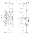
- FIGS. 1 to 3 show a stocker 2 and stocker units 12 according to an embodiment.
- FIG. 1 shows the overall structure of the stocker 2.
- the space between a pair of shelves 4, 4 is a transport device space, and a transport device such as stocker crane (not shown) travels through this space.
- some of the shelves 4, 4 are provided with a load port (not shown) for loading and unloading, and containers such as FOUPs or SMIF pods are exchanged with an overhead traveling vehicle (not shown) or the like.
- the transport device transports containers between a load port and a shelf 4, and between shelves 4, 4, for example.
- the front side of the shelves 4, 4 is the space 6 side, and the rear side of the shelves 4, 4 is the opposite side.
- Each stocker unit 12 includes a pair of vertical columns 14, 14 at the rear end, and also a purging line 18 constituted by a tube approximately parallel with the columns 14. Cleaning gas such as dry nitrogen or cleaned and dried air may be supplied from a pipeline or the like provided in the facility to the interior of containers.
- Multiple cell supports 16 are provided in a vertical arrangement in a state of being supported by a pair of columns 14, 14, and the purging line 18 vertically passes through the cell supports 16.
- Each cell support 16 is provided with nozzles 19, 19 for blowing cleaning gas into the container and a nozzle 20 for discharging cleaning gas from the container.
- each cell support 16 may be provided with one nozzle 19, and may also be provided with two nozzles 20 for discharge on the left and right sides. It should also be noted that in the case where the cleaning gas is naturally discharged through a gap between the body and the lid of the container, the nozzle 20 for discharge is not needed.
- 22 indicates load presence sensors that detect the presence and absence of a container supported on the cell support 16. Although each cell support 16 is provided with two load presence sensors 22, it may be provided with three or more, or one. Also, a configuration is possible in which the load presence sensors 22 are not provided, and the presence and absence of containers is determined based on data indicating the loading and unloading of containers onto and from the cell supports 16 by the transport device.
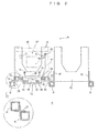
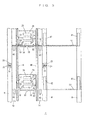
- FIGS. 2 and 3 show details of the stocker unit 12.
- the rear end portion of the cell support 16 is bent vertically upward and constitutes a vertical plate 24.
- a controller 26, a flow meter 36, and a valve 38 are attached to the vertical plate 24.
- a branch line 34 of each cell support 16 is connected to a purging line 18 via a joint 32, the controller 26 opens the valve 38 in accordance with a signal from the load presence sensors 22, and the flow rate in the branch line 34 is monitored by the flow meter 36 and fed back to the valve 38 such that the cleaning gas flows through the branch line 34 with a constant flow rate.
- the branch line 34 is bifurcated by a joint 39, and the nozzles 19, 19 introduce the cleaning gas into an FOUP 44 via gas introduction holes in the FOUP 44.
- the columns 8 correspond to the first columns in the claims
- the columns 14 correspond to the second columns in the claims
- the columns 8 are main parts of the frame of the stocker 2.
- the space between the front end of a column 14 and the rear end of a column 8, and particularly the space between the rear end of the FOUP 44 and the rear end of a column 8, tends to be empty space.
- the purging line 18, the controller 26, the flow meter 36, the valve 38, and the like are accommodated in this space.
- the columns 14, 14 are arranged diagonally forward of the columns 8, 8, and the gap between the columns 14, 14 is narrower than the gap between the columns 8, 8.
- the columns 14 are fastened to the respective columns 8 using an L-shaped member 28 and fastening members 30.
- the rear side of the FOUP 44 is shaped so as to be tapered toward the rear end in a plan view, that is to say is shaped such that the horizontal width decreases toward the rear end.
- a cutout shape may be formed by chamfering the left and right sides. This shape makes it possible to provide the columns 14 at positions that do not interfere with the FOUP 44.
- the L-shaped member may be arranged on the rear end side of each column 14 as shown by dashed lines 29 in FIG. 2 , or a cross-shaped attachment piece 31, for example, may be used as shown in the enlargement at the bottom of FIG. 2 .
- Appropriate design modification may be made according to the configuration of the stocker, for example.
- the horizontal width of the stocker unit 12 is approximately the same as the width of the cell supports 10, and the stocker unit 12 may be disposed between a pair of columns 8, 8 of a shelf 4.
- the purge function may be added to an existing stocker that does not have the purge function, for example, by incorporating the stocker unit 12.
- the stocker 2 may be provided with cell supports 16 having the purge function and cell supports 10 not having the purge function, and it is possible to remove a cell support 10 and replace it with a stocker unit 12, or remove a stocker unit 12 and replace it with a cell support 10.
- multiple cell supports 16 are aligned vertically in the stocker unit 12, they may be aligned horizontally.
- a pair of beams are provided in a vertically overlapping manner in place of the columns 14, 14, and the pair of beams are attached to beams or the like of the stocker frame.
- the tops and bottoms of the vertical plates 24 are then attached to the pair of horizontal beams.
- multiple cell supports 10 are aligned in the lengthwise direction of the beams.
- Cleaning gas is supplied to the purging line 18 by a pipeline provided in the facility.
- a portable gas bomb or the like may be used.
- a bomb or the like for supplying cleaning gas to the purging line 18 is arranged at an appropriate location, such as directly below a stocker unit 12.
- the stocker unit 12 may be manufactured separately from the stocker 2 and attached to the stocker 2 using the columns 8, 8.
Landscapes
- Engineering & Computer Science (AREA)
- Mechanical Engineering (AREA)
- Container, Conveyance, Adherence, Positioning, Of Wafer (AREA)
- Warehouses Or Storage Devices (AREA)
Abstract
Description
- This invention relates to a stocker having a purge function, a stocker unit, and a method for supplying cleaning gas to a container in a stocker.
- Workpieces handled in a clean room, such as semiconductor wafers and reticles, are transported and stored while being housed in a container such as an SMIF (Standard Mechanical Interface) pod or an FOUP (Front Opened Unified Pod). It has been proposed to keep the interior of the container locally clean by introducing a cleaning gas such as nitrogen (N2 gas) or cleaned and dried air through a gas inlet of the container. Nitrogen gas in particular also serves the role of preventing the formation of an oxide film on the surface of semiconductor wafers. Patent Literature 1 (
JP 2010-241515A WO 2008/106622 ) proposes an SMIF pod having a gas inlet for storing reticles. - With the stocker proposed in Patent Literature 1, all of the cells are compatible with the purge function, and it is not possible for cells compatible with the purge function and cells not compatible with the purge function to coexist. If some of the cells are not provided with a purging tube (purging line), those cells cannot be used for purging. If the purge function is to be added to an existing stocker that does not have purging lines, it is necessary to replace the existing stocker with a new stocker. In the case of altering the stocker in a clean room instead of replacing it with a new stocker, there are limits on the work time and work space, and the raising of dust needs to be prevented, thus making alteration difficult.
-
- Patent Literature 1:
JP 2010-241515A - Patent Literature 2:
WO 2008/106622 (JP 2010-520625A - An object of this invention is to provide a stocker in which cells having a purge function and cells not having the purge function may coexist, and a cell not having the purge function may be easily changed to a cell that has the purge function.
- A stocker having a purge function according to this invention includes:
- a frame to which a plurality of cell supports not having a cleaning gas supplying nozzle are configured to be attached along the vertical direction or the horizontal direction; and
- a stocker unit,
- the stocker unit comprising
- a base that comprises a column or a beam and is attached to the frame,
- a pipe for supplying cleaning gas that is provided along the base, and
- a plurality of cell supports having a purge function,
- the cell supports having a purge function being attached to the base, aligned along the vertical direction or the horizontal direction, configured to support a container, and each including a nozzle that supplies cleaning gas from the pipe to the container.
- Also, a stocker unit according to this invention includes:
- a base that is constituted by a column or a beam and is configured to be attached to a frame of a stocker;
- a pipe for supplying cleaning gas that is provided along the base; and
- a plurality of cell supports having a purge function that are attached to the base and are aligned along the vertical direction or the horizontal direction,
- the cell supports having a purge function being configured to support a container, and each including a nozzle that supplies cleaning gas from the pipe to the container.
- A method for supplying cleaning gas to a container according to this invention, with respect to a stocker having a frame to which a plurality of cell supports not having a cleaning gas supplying nozzle are configured to be attached along the vertical direction or the horizontal direction comprising:
- a step of attaching a stocker unit to the stocker, the stocker unit including a base constituted by a column or a beam, a pipe for supplying cleaning gas that is provided along the base, and a plurality of cell supports having a purge function that are attached to the base along the vertical direction or the horizontal direction and each include a nozzle that supplies cleaning gas from the pipe, and the stocker unit being attached to the stocker by attaching the base to the frame; and
- a step of supplying cleaning gas from the nozzles to the containers supported by the cell supports having a purge function.
- According to this invention, the purge function for supplying cleaning gas to a container through a nozzle may be added by attaching the stocker unit to the frame of the stocker. The stocker unit having the purge function and cell supports not having the purge function may be attached to the frame of the stocker. Also, the stocker unit having the purge function may be incorporated into an existing stocker. Note that in this specification, descriptions regarding the stocker directly apply to the stocker unit and the method for supplying a cleaning gas as well, and descriptions regarding the stocker unit directly apply to the stocker as well.
- It is preferable that the frame includes a container accommodating space and at least a pair of first columns at a rear end of the space,
- the base is constituted by at least a pair of second columns at a rear end of the container accommodating space,
- a gap between the second columns is narrower than a gap between the first columns, and
- the second columns are located diagonally forward of the first columns in a view from ahead of the container accommodating space, and are attached to the first columns.
- The stocker unit may be easily attached to the stocker by incorporating the stocker unit into the stocker such that the second columns of the stocker unit are located diagonally forward of the first columns of the frame of the stocker, and then attaching the second columns to the first columns.
- It is preferable that the cell supports having a purge function further include a branch line that supplies cleaning gas from the pipe to the nozzle, and a valve that controls the flow rate of cleaning gas in the branch line, and
in a view from ahead of the container accommodating space, the pipe and the valve are provided rearward of front ends of the second columns and forward of rear ends of the first columns. - The space rearward of the front ends of the second columns and forward of the rear ends of the first columns tends to be empty space that does not interfere with the container. A space-saving stocker unit may be achieved by providing the pipe and the valve in this space.
- It is preferable that a plurality of cell supports not having a cleaning gas supplying nozzle are attached to the frame, and the stocker unit is attached to the frame. In other words, cell supports not having the cleaning gas supplying nozzle and cell supports having the purge function and including the cleaning gas supplying nozzle coexist in the same stocker.
-
-
FIG. 1 is a plan view of a relevant portion of a stocker according to an embodiment. -
FIG. 2 is an enlarged plan view of a relevant portion ofFIG. 1 . -
FIG. 3 is an enlarged front view of a relevant portion of stocker shelves according to the embodiment. - The following describes a best mode for carrying out the present invention. The scope of the present invention is based on the recitation of the claims, and is intended to be determined in accordance with the understanding of a person skilled in the art with reference to the description of the present invention and well-known techniques in the field of the present invention.
-
FIGS. 1 to 3 show a stocker 2 andstocker units 12 according to an embodiment.FIG. 1 shows the overall structure of the stocker 2. For example, the space between a pair ofshelves shelves shelf 4, and betweenshelves shelves space 6 side, and the rear side of theshelves -
Multiple columns 8 are provided at the rear ends of theshelves columns stocker unit 12 having a purge function is attached to each pair ofcolumns stocker unit 12 includes a pair ofvertical columns purging line 18 constituted by a tube approximately parallel with thecolumns 14. Cleaning gas such as dry nitrogen or cleaned and dried air may be supplied from a pipeline or the like provided in the facility to the interior of containers. Multiple cell supports 16 are provided in a vertical arrangement in a state of being supported by a pair ofcolumns purging line 18 vertically passes through the cell supports 16. Eachcell support 16 is provided withnozzles nozzle 20 for discharging cleaning gas from the container. Note that eachcell support 16 may be provided with onenozzle 19, and may also be provided with twonozzles 20 for discharge on the left and right sides. It should also be noted that in the case where the cleaning gas is naturally discharged through a gap between the body and the lid of the container, thenozzle 20 for discharge is not needed. 22 indicates load presence sensors that detect the presence and absence of a container supported on thecell support 16. Although eachcell support 16 is provided with twoload presence sensors 22, it may be provided with three or more, or one. Also, a configuration is possible in which theload presence sensors 22 are not provided, and the presence and absence of containers is determined based on data indicating the loading and unloading of containers onto and from the cell supports 16 by the transport device. -
FIGS. 2 and3 show details of thestocker unit 12. The rear end portion of thecell support 16 is bent vertically upward and constitutes avertical plate 24. Acontroller 26, aflow meter 36, and avalve 38 are attached to thevertical plate 24. Abranch line 34 of eachcell support 16 is connected to apurging line 18 via a joint 32, thecontroller 26 opens thevalve 38 in accordance with a signal from theload presence sensors 22, and the flow rate in thebranch line 34 is monitored by theflow meter 36 and fed back to thevalve 38 such that the cleaning gas flows through thebranch line 34 with a constant flow rate. Thebranch line 34 is bifurcated by a joint 39, and thenozzles FOUP 44 via gas introduction holes in theFOUP 44. Note that 45 indicates a lid of theFOUP nozzle 20 is recovered via adischarge pipe 47 and adischarge line 48 constituted by a tube approximately parallel with thecolumns 14. Also, 42 indicates attachment members for attaching thecell support 10 to thecolumns 8. - The
columns 8 correspond to the first columns in the claims, thecolumns 14 correspond to the second columns in the claims, and thecolumns 8 are main parts of the frame of the stocker 2. The space between the front end of acolumn 14 and the rear end of acolumn 8, and particularly the space between the rear end of theFOUP 44 and the rear end of acolumn 8, tends to be empty space. In view of this, the purgingline 18, thecontroller 26, theflow meter 36, thevalve 38, and the like are accommodated in this space. Thecolumns columns columns columns columns 14 are fastened to therespective columns 8 using an L-shapedmember 28 andfastening members 30. Also, the rear side of theFOUP 44 is shaped so as to be tapered toward the rear end in a plan view, that is to say is shaped such that the horizontal width decreases toward the rear end. For example, even in the case of being arc-shaped in a plan view, a cutout shape may be formed by chamfering the left and right sides. This shape makes it possible to provide thecolumns 14 at positions that do not interfere with theFOUP 44. Note that the L-shaped member may be arranged on the rear end side of eachcolumn 14 as shown by dashedlines 29 inFIG. 2 , or across-shaped attachment piece 31, for example, may be used as shown in the enlargement at the bottom ofFIG. 2 . Appropriate design modification may be made according to the configuration of the stocker, for example. - The horizontal width of the
stocker unit 12 is approximately the same as the width of the cell supports 10, and thestocker unit 12 may be disposed between a pair ofcolumns shelf 4. For this reason, the purge function may be added to an existing stocker that does not have the purge function, for example, by incorporating thestocker unit 12. Also, the stocker 2 may be provided with cell supports 16 having the purge function and cell supports 10 not having the purge function, and it is possible to remove acell support 10 and replace it with astocker unit 12, or remove astocker unit 12 and replace it with acell support 10. - Although multiple cell supports 16 are aligned vertically in the
stocker unit 12, they may be aligned horizontally. In this case, a pair of beams are provided in a vertically overlapping manner in place of thecolumns vertical plates 24 are then attached to the pair of horizontal beams. In this case, multiple cell supports 10 are aligned in the lengthwise direction of the beams. - Cleaning gas is supplied to the
purging line 18 by a pipeline provided in the facility. Note that a portable gas bomb or the like may be used. In this case, a bomb or the like for supplying cleaning gas to thepurging line 18 is arranged at an appropriate location, such as directly below astocker unit 12. Also, thestocker unit 12 may be manufactured separately from the stocker 2 and attached to the stocker 2 using thecolumns - The following effects are obtained by the embodiment.
- 1) An existing stocker not having the purge function may be easily modified into a stocker 2 having the purge function.
- 2) Cell supports 16 having the purge function and cell supports 10 not having the purge function may be arranged in any ratio in the stocker 2.
- 3) By setting the gap between the
columns columns stocker unit 12 may be easily incorporated into the stocker 2 using the L-shapedmember 28. - 4) The
pipe 18, thecontroller 26, theflow meter 36, thevalve 38, and the like may be arranged in the empty space rearward of theFOUP 44. -
- 2
- Stocker
- 4
- Shelf
- 6
- Transport device space
- 8, 14
- Column
- 10, 16
- Cell support
- 12
- Stocker unit
- 18
- Purging line
- 19, 20
- Nozzle
- 22
- Load presence sensor
- 24
- Vertical plate
- 26
- Controller
- 28
- L-shaped member
- 30
- Fastening member
- 32, 39
- Joint
- 34
- Branch line
- 36
- Flow meter
- 38
- Valve
- 40, 42
- Attachment member
- 44
- FOUP
- 46
- Handle
- 47
- Discharge pipe
- 48
- Discharge line
Claims (6)
- A stocker having a purge function comprising:a frame to which a plurality of cell supports not having a cleaning gas supplying nozzle are configured to be attached along the vertical direction or the horizontal direction; anda stocker unit,the stocker unit comprisinga base that comprises a column or a beam and is attached to the frame,a pipe for supplying cleaning gas that is provided along the base, anda plurality of cell supports having a purge function,the cell supports having a purge function being attached to the base, aligned along the vertical direction or the horizontal direction, configured to support a container, and each including a nozzle that supplies cleaning gas from the pipe to the container.
- The stocker having a purge function according to claim 1,
wherein the frame includes a container accommodating space and at least a pair of first columns at a rear end of the space,
the base is constituted by at least a pair of second columns at a rear end of the container accommodating space,
a gap between the second columns is narrower than a gap between the first columns, and
the second columns are located diagonally forward of the first columns in a view from ahead of the container accommodating space, and are attached to the first columns. - The stocker having a purge function according to claim 2,
wherein the cell supports having a purge function further include a branch line that supplies cleaning gas from the pipe to the nozzle, and a valve that controls the flow rate of cleaning gas in the branch line, and
in a view from ahead of the container accommodating space, the pipe and the valve are provided rearward of front ends of the second columns and forward of rear ends of the first columns. - The stocker having a purge function according to claim 2 or 3, wherein a plurality of cell supports not having a cleaning gas supplying nozzle are attached to the frame, and the stocker unit is attached to the frame.
- A stocker unit comprising:a base that comprises a column or a beam and is configured to be attached to a frame of a stocker;a pipe for supplying cleaning gas that is provided along the base; anda plurality of cell supports having a purge function that are attached to the base and are aligned along the vertical direction or the horizontal direction,the cell supports having a purge function being configured to support a container, and each including a nozzle that supplies cleaning gas from the pipe to the container.
- A method for supplying cleaning gas to a container with respect to a stocker having a frame to which a plurality of cell supports not having a cleaning gas supplying nozzle are configured to be attached along the vertical direction or the horizontal direction comprising:a step for attaching a stocker unit to the stocker, the stocker unit including a base constituted by a column or a beam, a pipe for supplying cleaning gas that is provided along the base, and a plurality of cell supports having a purge function that are attached to the base along the vertical direction or the horizontal direction and each include a nozzle that supplies cleaning gas from the pipe, and the stocker unit being attached to the stocker by attaching the base to the frame; anda step for supplying cleaning gas from the nozzles to the containers supported by the cell supports having a purge function.
Applications Claiming Priority (2)
| Application Number | Priority Date | Filing Date | Title |
|---|---|---|---|
| JP2012182191 | 2012-08-21 | ||
| PCT/JP2013/067083 WO2014030421A1 (en) | 2012-08-21 | 2013-06-21 | Stocker provided with purging functionality, stocker unit, and method for supplying cleaning gas |
Publications (3)
| Publication Number | Publication Date |
|---|---|
| EP2889235A1 true EP2889235A1 (en) | 2015-07-01 |
| EP2889235A4 EP2889235A4 (en) | 2016-04-27 |
| EP2889235B1 EP2889235B1 (en) | 2020-08-05 |
Family
ID=50149738
Family Applications (1)
| Application Number | Title | Priority Date | Filing Date |
|---|---|---|---|
| EP13830946.3A Active EP2889235B1 (en) | 2012-08-21 | 2013-06-21 | Stocker provided with purging functionality, stocker unit, and method for supplying cleaning gas |
Country Status (8)
| Country | Link |
|---|---|
| US (1) | US9878353B2 (en) |
| EP (1) | EP2889235B1 (en) |
| JP (1) | JP6021046B2 (en) |
| KR (1) | KR101679734B1 (en) |
| CN (1) | CN104603032B (en) |
| IL (1) | IL236345A (en) |
| TW (1) | TWI570042B (en) |
| WO (1) | WO2014030421A1 (en) |
Families Citing this family (17)
| Publication number | Priority date | Publication date | Assignee | Title |
|---|---|---|---|---|
| KR101418812B1 (en) * | 2012-10-31 | 2014-07-16 | 크린팩토메이션 주식회사 | Apparatus for stocking and purging wafer at ceiling |
| JP5874691B2 (en) * | 2013-06-26 | 2016-03-02 | 株式会社ダイフク | Inert gas supply equipment |
| JP6217855B2 (en) * | 2014-06-16 | 2017-10-25 | 村田機械株式会社 | Purge apparatus, purge system, purge method, and control method in purge system |
| KR101593386B1 (en) | 2014-09-01 | 2016-02-15 | 로체 시스템즈(주) | Purge module and load port having the same |
| KR101609338B1 (en) * | 2015-03-16 | 2016-04-05 | 크린팩토메이션 주식회사 | Apparatus for storing and handling wafer carrier at ceiling |
| WO2016189975A1 (en) * | 2015-05-26 | 2016-12-01 | 村田機械株式会社 | Multistage shelf and overhead traveling vehicle system using same |
| US10586721B2 (en) * | 2015-08-25 | 2020-03-10 | Murata Machinery, Ltd. | Purge device, purge stocker, and purge method |
| JP6414525B2 (en) * | 2015-09-02 | 2018-10-31 | 株式会社ダイフク | Storage facilities |
| CN106505023B (en) * | 2015-09-08 | 2020-04-10 | 华景电通股份有限公司 | Wafer conveying device with blowing-clean function |
| JP6551240B2 (en) * | 2016-01-06 | 2019-07-31 | 株式会社ダイフク | Article storage rack and article storage facility provided with the same |
| JP6794898B2 (en) * | 2017-03-29 | 2020-12-02 | 株式会社ダイフク | Storage rack |
| KR101866788B1 (en) | 2018-01-22 | 2018-06-18 | 보은에스앤씨 주식회사 | Welding tip processing method for semiconductor pipe welding |
| KR101878363B1 (en) | 2018-01-22 | 2018-07-16 | 보은에스앤씨 주식회사 | Cap for easy welding |
| KR102128483B1 (en) * | 2018-09-27 | 2020-06-30 | 크린팩토메이션 주식회사 | Shelf assembly eanble to purge wafer and buffer module having the same |
| KR102764783B1 (en) * | 2020-03-05 | 2025-02-11 | 무라다기카이가부시끼가이샤 | Storage Shelf |
| US12030091B2 (en) | 2020-07-30 | 2024-07-09 | Changxin Memory Technologies, Inc. | Cleaning system for semiconductor storage shelf |
| KR102808258B1 (en) * | 2021-03-11 | 2025-05-14 | 세메스 주식회사 | Material storage apparatus and logistics management equipment including the same |
Family Cites Families (15)
| Publication number | Priority date | Publication date | Assignee | Title |
|---|---|---|---|---|
| US6579052B1 (en) * | 1997-07-11 | 2003-06-17 | Asyst Technologies, Inc. | SMIF pod storage, delivery and retrieval system |
| JPH11168135A (en) * | 1997-12-03 | 1999-06-22 | Toshiba Corp | Substrate storage device and substrate storage method |
| US6079927A (en) * | 1998-04-22 | 2000-06-27 | Varian Semiconductor Equipment Associates, Inc. | Automated wafer buffer for use with wafer processing equipment |
| JPH11314703A (en) * | 1998-04-30 | 1999-11-16 | Ebara Corp | Substrate storage device |
| JP4308975B2 (en) * | 1999-05-27 | 2009-08-05 | 株式会社日立国際電気 | Substrate processing apparatus, substrate processing method, and semiconductor element forming method |
| US6506009B1 (en) * | 2000-03-16 | 2003-01-14 | Applied Materials, Inc. | Apparatus for storing and moving a cassette |
| US6745908B2 (en) * | 2001-06-30 | 2004-06-08 | Applied Materials, Inc. | Shelf module adapted to store substrate carriers |
| JP2003292118A (en) * | 2002-04-05 | 2003-10-15 | Murata Mach Ltd | Automatic storage and retrieval warehouse |
| JP4670808B2 (en) * | 2006-12-22 | 2011-04-13 | ムラテックオートメーション株式会社 | Container transport system and measuring container |
| JP4378652B2 (en) * | 2007-01-10 | 2009-12-09 | 株式会社ダイフク | Purified air ventilation-type goods storage facility |
| US8146623B2 (en) | 2007-02-28 | 2012-04-03 | Entegris, Inc. | Purge system for a substrate container |
| JP4688000B2 (en) * | 2008-02-06 | 2011-05-25 | 株式会社ダイフク | Goods storage equipment |
| TWI357474B (en) * | 2008-10-14 | 2012-02-01 | Gudeng Prec Industral Co Ltd | Gas filling socket, gas filling socket set, and ga |
| JP5236518B2 (en) * | 2009-02-03 | 2013-07-17 | 株式会社ダン・タクマ | Storage system and storage method |
| JP2010241515A (en) | 2009-04-01 | 2010-10-28 | Murata Machinery Ltd | Storage warehouse |
-
2013
- 2013-06-21 WO PCT/JP2013/067083 patent/WO2014030421A1/en not_active Ceased
- 2013-06-21 CN CN201380043277.6A patent/CN104603032B/en active Active
- 2013-06-21 KR KR1020157004131A patent/KR101679734B1/en active Active
- 2013-06-21 EP EP13830946.3A patent/EP2889235B1/en active Active
- 2013-06-21 JP JP2014531533A patent/JP6021046B2/en active Active
- 2013-06-21 US US14/421,215 patent/US9878353B2/en active Active
- 2013-08-15 TW TW102129259A patent/TWI570042B/en active
-
2014
- 2014-12-18 IL IL236345A patent/IL236345A/en active IP Right Grant
Also Published As
| Publication number | Publication date |
|---|---|
| KR20150034272A (en) | 2015-04-02 |
| CN104603032B (en) | 2016-12-07 |
| IL236345A (en) | 2016-11-30 |
| CN104603032A (en) | 2015-05-06 |
| US9878353B2 (en) | 2018-01-30 |
| EP2889235B1 (en) | 2020-08-05 |
| TWI570042B (en) | 2017-02-11 |
| JPWO2014030421A1 (en) | 2016-07-28 |
| EP2889235A4 (en) | 2016-04-27 |
| KR101679734B1 (en) | 2016-11-25 |
| TW201418121A (en) | 2014-05-16 |
| US20150202664A1 (en) | 2015-07-23 |
| WO2014030421A1 (en) | 2014-02-27 |
| JP6021046B2 (en) | 2016-11-02 |
| IL236345A0 (en) | 2015-02-26 |
Similar Documents
| Publication | Publication Date | Title |
|---|---|---|
| US9878353B2 (en) | Stocker provided with purging functionality, stocker unit, and method for supplying cleaning gas | |
| TWI644266B (en) | Ceiling storage system and method for storing goods in ceiling space | |
| CN103171843B (en) | Article storage apparatus and article keeping method | |
| KR20180082380A (en) | Wafer transfer pod for reducing wafer particulate contamination | |
| CN103171854B (en) | Article keeping apparatus and article keeping method | |
| TWI610866B (en) | Item storage equipment | |
| JP6614174B2 (en) | Flow measurement system | |
| US20080170932A1 (en) | Apparatus and method for supplying articles to processing tool | |
| JP6217281B2 (en) | Automatic warehouse and gas supply method | |
| US20090022575A1 (en) | Article storing apparatus | |
| US20150340253A1 (en) | Semiconductor processing assembly and facility | |
| KR20160034402A (en) | Substrate processing device, manufacturing method for semiconductor device, and recording medium | |
| KR102839878B1 (en) | Article storage facility | |
| TWI236999B (en) | Processing and keeping apparatus | |
| US20240317492A1 (en) | Distribution storage system | |
| KR102419509B1 (en) | Article transport facility | |
| JP2006186095A (en) | Tray transport system | |
| JP2006114561A (en) | Wafer transfer cart |
Legal Events
| Date | Code | Title | Description |
|---|---|---|---|
| PUAI | Public reference made under article 153(3) epc to a published international application that has entered the european phase |
Free format text: ORIGINAL CODE: 0009012 |
|
| 17P | Request for examination filed |
Effective date: 20150313 |
|
| AK | Designated contracting states |
Kind code of ref document: A1 Designated state(s): AL AT BE BG CH CY CZ DE DK EE ES FI FR GB GR HR HU IE IS IT LI LT LU LV MC MK MT NL NO PL PT RO RS SE SI SK SM TR |
|
| AX | Request for extension of the european patent |
Extension state: BA ME |
|
| DAX | Request for extension of the european patent (deleted) | ||
| RA4 | Supplementary search report drawn up and despatched (corrected) |
Effective date: 20160331 |
|
| RIC1 | Information provided on ipc code assigned before grant |
Ipc: H01L 21/677 20060101ALI20160323BHEP Ipc: B65G 1/14 20060101AFI20160323BHEP Ipc: B65G 1/00 20060101ALI20160323BHEP Ipc: H01L 21/673 20060101ALI20160323BHEP Ipc: B08B 5/02 20060101ALI20160323BHEP Ipc: B65G 45/00 20060101ALI20160323BHEP |
|
| GRAP | Despatch of communication of intention to grant a patent |
Free format text: ORIGINAL CODE: EPIDOSNIGR1 |
|
| STAA | Information on the status of an ep patent application or granted ep patent |
Free format text: STATUS: GRANT OF PATENT IS INTENDED |
|
| INTG | Intention to grant announced |
Effective date: 20200227 |
|
| GRAS | Grant fee paid |
Free format text: ORIGINAL CODE: EPIDOSNIGR3 |
|
| GRAA | (expected) grant |
Free format text: ORIGINAL CODE: 0009210 |
|
| STAA | Information on the status of an ep patent application or granted ep patent |
Free format text: STATUS: THE PATENT HAS BEEN GRANTED |
|
| AK | Designated contracting states |
Kind code of ref document: B1 Designated state(s): AL AT BE BG CH CY CZ DE DK EE ES FI FR GB GR HR HU IE IS IT LI LT LU LV MC MK MT NL NO PL PT RO RS SE SI SK SM TR |
|
| REG | Reference to a national code |
Ref country code: GB Ref legal event code: FG4D |
|
| REG | Reference to a national code |
Ref country code: CH Ref legal event code: EP |
|
| REG | Reference to a national code |
Ref country code: AT Ref legal event code: REF Ref document number: 1298432 Country of ref document: AT Kind code of ref document: T Effective date: 20200815 |
|
| REG | Reference to a national code |
Ref country code: DE Ref legal event code: R096 Ref document number: 602013071403 Country of ref document: DE |
|
| REG | Reference to a national code |
Ref country code: IE Ref legal event code: FG4D |
|
| REG | Reference to a national code |
Ref country code: LT Ref legal event code: MG4D |
|
| REG | Reference to a national code |
Ref country code: NL Ref legal event code: MP Effective date: 20200805 |
|
| REG | Reference to a national code |
Ref country code: AT Ref legal event code: MK05 Ref document number: 1298432 Country of ref document: AT Kind code of ref document: T Effective date: 20200805 |
|
| PG25 | Lapsed in a contracting state [announced via postgrant information from national office to epo] |
Ref country code: HR Free format text: LAPSE BECAUSE OF FAILURE TO SUBMIT A TRANSLATION OF THE DESCRIPTION OR TO PAY THE FEE WITHIN THE PRESCRIBED TIME-LIMIT Effective date: 20200805 Ref country code: PT Free format text: LAPSE BECAUSE OF FAILURE TO SUBMIT A TRANSLATION OF THE DESCRIPTION OR TO PAY THE FEE WITHIN THE PRESCRIBED TIME-LIMIT Effective date: 20201207 Ref country code: FI Free format text: LAPSE BECAUSE OF FAILURE TO SUBMIT A TRANSLATION OF THE DESCRIPTION OR TO PAY THE FEE WITHIN THE PRESCRIBED TIME-LIMIT Effective date: 20200805 Ref country code: LT Free format text: LAPSE BECAUSE OF FAILURE TO SUBMIT A TRANSLATION OF THE DESCRIPTION OR TO PAY THE FEE WITHIN THE PRESCRIBED TIME-LIMIT Effective date: 20200805 Ref country code: ES Free format text: LAPSE BECAUSE OF FAILURE TO SUBMIT A TRANSLATION OF THE DESCRIPTION OR TO PAY THE FEE WITHIN THE PRESCRIBED TIME-LIMIT Effective date: 20200805 Ref country code: GR Free format text: LAPSE BECAUSE OF FAILURE TO SUBMIT A TRANSLATION OF THE DESCRIPTION OR TO PAY THE FEE WITHIN THE PRESCRIBED TIME-LIMIT Effective date: 20201106 Ref country code: NO Free format text: LAPSE BECAUSE OF FAILURE TO SUBMIT A TRANSLATION OF THE DESCRIPTION OR TO PAY THE FEE WITHIN THE PRESCRIBED TIME-LIMIT Effective date: 20201105 Ref country code: BG Free format text: LAPSE BECAUSE OF FAILURE TO SUBMIT A TRANSLATION OF THE DESCRIPTION OR TO PAY THE FEE WITHIN THE PRESCRIBED TIME-LIMIT Effective date: 20201105 Ref country code: SE Free format text: LAPSE BECAUSE OF FAILURE TO SUBMIT A TRANSLATION OF THE DESCRIPTION OR TO PAY THE FEE WITHIN THE PRESCRIBED TIME-LIMIT Effective date: 20200805 Ref country code: AT Free format text: LAPSE BECAUSE OF FAILURE TO SUBMIT A TRANSLATION OF THE DESCRIPTION OR TO PAY THE FEE WITHIN THE PRESCRIBED TIME-LIMIT Effective date: 20200805 |
|
| PG25 | Lapsed in a contracting state [announced via postgrant information from national office to epo] |
Ref country code: IS Free format text: LAPSE BECAUSE OF FAILURE TO SUBMIT A TRANSLATION OF THE DESCRIPTION OR TO PAY THE FEE WITHIN THE PRESCRIBED TIME-LIMIT Effective date: 20201205 Ref country code: NL Free format text: LAPSE BECAUSE OF FAILURE TO SUBMIT A TRANSLATION OF THE DESCRIPTION OR TO PAY THE FEE WITHIN THE PRESCRIBED TIME-LIMIT Effective date: 20200805 Ref country code: LV Free format text: LAPSE BECAUSE OF FAILURE TO SUBMIT A TRANSLATION OF THE DESCRIPTION OR TO PAY THE FEE WITHIN THE PRESCRIBED TIME-LIMIT Effective date: 20200805 Ref country code: PL Free format text: LAPSE BECAUSE OF FAILURE TO SUBMIT A TRANSLATION OF THE DESCRIPTION OR TO PAY THE FEE WITHIN THE PRESCRIBED TIME-LIMIT Effective date: 20200805 Ref country code: RS Free format text: LAPSE BECAUSE OF FAILURE TO SUBMIT A TRANSLATION OF THE DESCRIPTION OR TO PAY THE FEE WITHIN THE PRESCRIBED TIME-LIMIT Effective date: 20200805 |
|
| PG25 | Lapsed in a contracting state [announced via postgrant information from national office to epo] |
Ref country code: SM Free format text: LAPSE BECAUSE OF FAILURE TO SUBMIT A TRANSLATION OF THE DESCRIPTION OR TO PAY THE FEE WITHIN THE PRESCRIBED TIME-LIMIT Effective date: 20200805 Ref country code: RO Free format text: LAPSE BECAUSE OF FAILURE TO SUBMIT A TRANSLATION OF THE DESCRIPTION OR TO PAY THE FEE WITHIN THE PRESCRIBED TIME-LIMIT Effective date: 20200805 Ref country code: DK Free format text: LAPSE BECAUSE OF FAILURE TO SUBMIT A TRANSLATION OF THE DESCRIPTION OR TO PAY THE FEE WITHIN THE PRESCRIBED TIME-LIMIT Effective date: 20200805 Ref country code: EE Free format text: LAPSE BECAUSE OF FAILURE TO SUBMIT A TRANSLATION OF THE DESCRIPTION OR TO PAY THE FEE WITHIN THE PRESCRIBED TIME-LIMIT Effective date: 20200805 Ref country code: CZ Free format text: LAPSE BECAUSE OF FAILURE TO SUBMIT A TRANSLATION OF THE DESCRIPTION OR TO PAY THE FEE WITHIN THE PRESCRIBED TIME-LIMIT Effective date: 20200805 |
|
| REG | Reference to a national code |
Ref country code: DE Ref legal event code: R097 Ref document number: 602013071403 Country of ref document: DE |
|
| PG25 | Lapsed in a contracting state [announced via postgrant information from national office to epo] |
Ref country code: AL Free format text: LAPSE BECAUSE OF FAILURE TO SUBMIT A TRANSLATION OF THE DESCRIPTION OR TO PAY THE FEE WITHIN THE PRESCRIBED TIME-LIMIT Effective date: 20200805 |
|
| PLBE | No opposition filed within time limit |
Free format text: ORIGINAL CODE: 0009261 |
|
| STAA | Information on the status of an ep patent application or granted ep patent |
Free format text: STATUS: NO OPPOSITION FILED WITHIN TIME LIMIT |
|
| PG25 | Lapsed in a contracting state [announced via postgrant information from national office to epo] |
Ref country code: SK Free format text: LAPSE BECAUSE OF FAILURE TO SUBMIT A TRANSLATION OF THE DESCRIPTION OR TO PAY THE FEE WITHIN THE PRESCRIBED TIME-LIMIT Effective date: 20200805 |
|
| 26N | No opposition filed |
Effective date: 20210507 |
|
| PG25 | Lapsed in a contracting state [announced via postgrant information from national office to epo] |
Ref country code: IT Free format text: LAPSE BECAUSE OF FAILURE TO SUBMIT A TRANSLATION OF THE DESCRIPTION OR TO PAY THE FEE WITHIN THE PRESCRIBED TIME-LIMIT Effective date: 20200805 |
|
| PG25 | Lapsed in a contracting state [announced via postgrant information from national office to epo] |
Ref country code: SI Free format text: LAPSE BECAUSE OF FAILURE TO SUBMIT A TRANSLATION OF THE DESCRIPTION OR TO PAY THE FEE WITHIN THE PRESCRIBED TIME-LIMIT Effective date: 20200805 |
|
| PG25 | Lapsed in a contracting state [announced via postgrant information from national office to epo] |
Ref country code: MC Free format text: LAPSE BECAUSE OF FAILURE TO SUBMIT A TRANSLATION OF THE DESCRIPTION OR TO PAY THE FEE WITHIN THE PRESCRIBED TIME-LIMIT Effective date: 20200805 |
|
| REG | Reference to a national code |
Ref country code: CH Ref legal event code: PL |
|
| GBPC | Gb: european patent ceased through non-payment of renewal fee |
Effective date: 20210621 |
|
| REG | Reference to a national code |
Ref country code: BE Ref legal event code: MM Effective date: 20210630 |
|
| PG25 | Lapsed in a contracting state [announced via postgrant information from national office to epo] |
Ref country code: LU Free format text: LAPSE BECAUSE OF NON-PAYMENT OF DUE FEES Effective date: 20210621 |
|
| PG25 | Lapsed in a contracting state [announced via postgrant information from national office to epo] |
Ref country code: LI Free format text: LAPSE BECAUSE OF NON-PAYMENT OF DUE FEES Effective date: 20210630 Ref country code: GB Free format text: LAPSE BECAUSE OF NON-PAYMENT OF DUE FEES Effective date: 20210621 Ref country code: CH Free format text: LAPSE BECAUSE OF NON-PAYMENT OF DUE FEES Effective date: 20210630 |
|
| PG25 | Lapsed in a contracting state [announced via postgrant information from national office to epo] |
Ref country code: FR Free format text: LAPSE BECAUSE OF NON-PAYMENT OF DUE FEES Effective date: 20210630 |
|
| PG25 | Lapsed in a contracting state [announced via postgrant information from national office to epo] |
Ref country code: BE Free format text: LAPSE BECAUSE OF NON-PAYMENT OF DUE FEES Effective date: 20210630 |
|
| PG25 | Lapsed in a contracting state [announced via postgrant information from national office to epo] |
Ref country code: HU Free format text: LAPSE BECAUSE OF FAILURE TO SUBMIT A TRANSLATION OF THE DESCRIPTION OR TO PAY THE FEE WITHIN THE PRESCRIBED TIME-LIMIT; INVALID AB INITIO Effective date: 20130621 |
|
| PG25 | Lapsed in a contracting state [announced via postgrant information from national office to epo] |
Ref country code: CY Free format text: LAPSE BECAUSE OF FAILURE TO SUBMIT A TRANSLATION OF THE DESCRIPTION OR TO PAY THE FEE WITHIN THE PRESCRIBED TIME-LIMIT Effective date: 20200805 |
|
| PG25 | Lapsed in a contracting state [announced via postgrant information from national office to epo] |
Ref country code: MK Free format text: LAPSE BECAUSE OF FAILURE TO SUBMIT A TRANSLATION OF THE DESCRIPTION OR TO PAY THE FEE WITHIN THE PRESCRIBED TIME-LIMIT Effective date: 20200805 |
|
| PG25 | Lapsed in a contracting state [announced via postgrant information from national office to epo] |
Ref country code: TR Free format text: LAPSE BECAUSE OF FAILURE TO SUBMIT A TRANSLATION OF THE DESCRIPTION OR TO PAY THE FEE WITHIN THE PRESCRIBED TIME-LIMIT Effective date: 20200805 |
|
| PG25 | Lapsed in a contracting state [announced via postgrant information from national office to epo] |
Ref country code: MT Free format text: LAPSE BECAUSE OF FAILURE TO SUBMIT A TRANSLATION OF THE DESCRIPTION OR TO PAY THE FEE WITHIN THE PRESCRIBED TIME-LIMIT Effective date: 20200805 |
|
| PGFP | Annual fee paid to national office [announced via postgrant information from national office to epo] |
Ref country code: DE Payment date: 20250520 Year of fee payment: 13 |
|
| PGFP | Annual fee paid to national office [announced via postgrant information from national office to epo] |
Ref country code: IE Payment date: 20250522 Year of fee payment: 13 |