EP2889224A1 - Portion capsule for preparing a brewed product and method for producing the same - Google Patents
Portion capsule for preparing a brewed product and method for producing the same Download PDFInfo
- Publication number
- EP2889224A1 EP2889224A1 EP13199515.1A EP13199515A EP2889224A1 EP 2889224 A1 EP2889224 A1 EP 2889224A1 EP 13199515 A EP13199515 A EP 13199515A EP 2889224 A1 EP2889224 A1 EP 2889224A1
- Authority
- EP
- European Patent Office
- Prior art keywords
- collar
- lid
- base body
- capsule
- circumferential
- Prior art date
- Legal status (The legal status is an assumption and is not a legal conclusion. Google has not performed a legal analysis and makes no representation as to the accuracy of the status listed.)
- Granted
Links
- 239000002775 capsule Substances 0.000 title claims abstract description 72
- 238000004519 manufacturing process Methods 0.000 title claims abstract description 16
- 238000000034 method Methods 0.000 claims abstract description 20
- 238000003466 welding Methods 0.000 claims abstract description 19
- 238000000605 extraction Methods 0.000 claims abstract description 14
- 239000000463 material Substances 0.000 claims abstract description 14
- 238000002604 ultrasonography Methods 0.000 claims abstract description 3
- 230000008569 process Effects 0.000 claims description 10
- 239000004033 plastic Substances 0.000 claims description 8
- 229920003023 plastic Polymers 0.000 claims description 8
- 230000007704 transition Effects 0.000 claims description 8
- 238000001746 injection moulding Methods 0.000 claims description 5
- 230000002093 peripheral effect Effects 0.000 abstract description 2
- -1 Polypropylene Polymers 0.000 description 4
- 239000004743 Polypropylene Substances 0.000 description 4
- 235000016213 coffee Nutrition 0.000 description 4
- 235000013353 coffee beverage Nutrition 0.000 description 4
- 229920001155 polypropylene Polymers 0.000 description 4
- 230000004888 barrier function Effects 0.000 description 3
- 230000008901 benefit Effects 0.000 description 3
- 235000013361 beverage Nutrition 0.000 description 3
- 238000004806 packaging method and process Methods 0.000 description 3
- 229920000219 Ethylene vinyl alcohol Polymers 0.000 description 2
- 241001122767 Theaceae Species 0.000 description 2
- XAGFODPZIPBFFR-UHFFFAOYSA-N aluminium Chemical compound [Al] XAGFODPZIPBFFR-UHFFFAOYSA-N 0.000 description 2
- 229910052782 aluminium Inorganic materials 0.000 description 2
- QVGXLLKOCUKJST-UHFFFAOYSA-N atomic oxygen Chemical compound [O] QVGXLLKOCUKJST-UHFFFAOYSA-N 0.000 description 2
- 238000004049 embossing Methods 0.000 description 2
- 229910052760 oxygen Inorganic materials 0.000 description 2
- 239000001301 oxygen Substances 0.000 description 2
- 238000002360 preparation method Methods 0.000 description 2
- 238000007789 sealing Methods 0.000 description 2
- 239000006228 supernatant Substances 0.000 description 2
- 235000013616 tea Nutrition 0.000 description 2
- 230000008719 thickening Effects 0.000 description 2
- 230000009286 beneficial effect Effects 0.000 description 1
- 230000000295 complement effect Effects 0.000 description 1
- 238000009792 diffusion process Methods 0.000 description 1
- 238000005265 energy consumption Methods 0.000 description 1
- 238000005516 engineering process Methods 0.000 description 1
- 235000015114 espresso Nutrition 0.000 description 1
- 239000004715 ethylene vinyl alcohol Substances 0.000 description 1
- 230000001771 impaired effect Effects 0.000 description 1
- 239000007788 liquid Substances 0.000 description 1
- 230000007246 mechanism Effects 0.000 description 1
- 239000012528 membrane Substances 0.000 description 1
- 239000000047 product Substances 0.000 description 1
- 238000004080 punching Methods 0.000 description 1
- 238000000926 separation method Methods 0.000 description 1
- 238000004513 sizing Methods 0.000 description 1
- 239000003351 stiffener Substances 0.000 description 1
- 238000003856 thermoforming Methods 0.000 description 1
- XLYOFNOQVPJJNP-UHFFFAOYSA-N water Substances O XLYOFNOQVPJJNP-UHFFFAOYSA-N 0.000 description 1
Images

Classifications
-
- B—PERFORMING OPERATIONS; TRANSPORTING
- B29—WORKING OF PLASTICS; WORKING OF SUBSTANCES IN A PLASTIC STATE IN GENERAL
- B29C—SHAPING OR JOINING OF PLASTICS; SHAPING OF MATERIAL IN A PLASTIC STATE, NOT OTHERWISE PROVIDED FOR; AFTER-TREATMENT OF THE SHAPED PRODUCTS, e.g. REPAIRING
- B29C65/00—Joining or sealing of preformed parts, e.g. welding of plastics materials; Apparatus therefor
- B29C65/02—Joining or sealing of preformed parts, e.g. welding of plastics materials; Apparatus therefor by heating, with or without pressure
- B29C65/08—Joining or sealing of preformed parts, e.g. welding of plastics materials; Apparatus therefor by heating, with or without pressure using ultrasonic vibrations
-
- B—PERFORMING OPERATIONS; TRANSPORTING
- B29—WORKING OF PLASTICS; WORKING OF SUBSTANCES IN A PLASTIC STATE IN GENERAL
- B29C—SHAPING OR JOINING OF PLASTICS; SHAPING OF MATERIAL IN A PLASTIC STATE, NOT OTHERWISE PROVIDED FOR; AFTER-TREATMENT OF THE SHAPED PRODUCTS, e.g. REPAIRING
- B29C66/00—General aspects of processes or apparatus for joining preformed parts
- B29C66/01—General aspects dealing with the joint area or with the area to be joined
- B29C66/05—Particular design of joint configurations
- B29C66/10—Particular design of joint configurations particular design of the joint cross-sections
- B29C66/13—Single flanged joints; Fin-type joints; Single hem joints; Edge joints; Interpenetrating fingered joints; Other specific particular designs of joint cross-sections not provided for in groups B29C66/11 - B29C66/12
- B29C66/131—Single flanged joints, i.e. one of the parts to be joined being rigid and flanged in the joint area
- B29C66/1312—Single flange to flange joints, the parts to be joined being rigid
-
- B—PERFORMING OPERATIONS; TRANSPORTING
- B29—WORKING OF PLASTICS; WORKING OF SUBSTANCES IN A PLASTIC STATE IN GENERAL
- B29C—SHAPING OR JOINING OF PLASTICS; SHAPING OF MATERIAL IN A PLASTIC STATE, NOT OTHERWISE PROVIDED FOR; AFTER-TREATMENT OF THE SHAPED PRODUCTS, e.g. REPAIRING
- B29C66/00—General aspects of processes or apparatus for joining preformed parts
- B29C66/01—General aspects dealing with the joint area or with the area to be joined
- B29C66/05—Particular design of joint configurations
- B29C66/20—Particular design of joint configurations particular design of the joint lines, e.g. of the weld lines
- B29C66/24—Particular design of joint configurations particular design of the joint lines, e.g. of the weld lines said joint lines being closed or non-straight
- B29C66/242—Particular design of joint configurations particular design of the joint lines, e.g. of the weld lines said joint lines being closed or non-straight said joint lines being closed, i.e. forming closed contours
- B29C66/2424—Particular design of joint configurations particular design of the joint lines, e.g. of the weld lines said joint lines being closed or non-straight said joint lines being closed, i.e. forming closed contours being a closed polygonal chain
- B29C66/24243—Particular design of joint configurations particular design of the joint lines, e.g. of the weld lines said joint lines being closed or non-straight said joint lines being closed, i.e. forming closed contours being a closed polygonal chain forming a quadrilateral
- B29C66/24244—Particular design of joint configurations particular design of the joint lines, e.g. of the weld lines said joint lines being closed or non-straight said joint lines being closed, i.e. forming closed contours being a closed polygonal chain forming a quadrilateral forming a rectangle
- B29C66/24245—Particular design of joint configurations particular design of the joint lines, e.g. of the weld lines said joint lines being closed or non-straight said joint lines being closed, i.e. forming closed contours being a closed polygonal chain forming a quadrilateral forming a rectangle forming a square
-
- B—PERFORMING OPERATIONS; TRANSPORTING
- B29—WORKING OF PLASTICS; WORKING OF SUBSTANCES IN A PLASTIC STATE IN GENERAL
- B29C—SHAPING OR JOINING OF PLASTICS; SHAPING OF MATERIAL IN A PLASTIC STATE, NOT OTHERWISE PROVIDED FOR; AFTER-TREATMENT OF THE SHAPED PRODUCTS, e.g. REPAIRING
- B29C66/00—General aspects of processes or apparatus for joining preformed parts
- B29C66/50—General aspects of joining tubular articles; General aspects of joining long products, i.e. bars or profiled elements; General aspects of joining single elements to tubular articles, hollow articles or bars; General aspects of joining several hollow-preforms to form hollow or tubular articles
- B29C66/51—Joining tubular articles, profiled elements or bars; Joining single elements to tubular articles, hollow articles or bars; Joining several hollow-preforms to form hollow or tubular articles
- B29C66/54—Joining several hollow-preforms, e.g. half-shells, to form hollow articles, e.g. for making balls, containers; Joining several hollow-preforms, e.g. half-cylinders, to form tubular articles
- B29C66/542—Joining several hollow-preforms, e.g. half-shells, to form hollow articles, e.g. for making balls, containers; Joining several hollow-preforms, e.g. half-cylinders, to form tubular articles joining hollow covers or hollow bottoms to open ends of container bodies
-
- B—PERFORMING OPERATIONS; TRANSPORTING
- B29—WORKING OF PLASTICS; WORKING OF SUBSTANCES IN A PLASTIC STATE IN GENERAL
- B29C—SHAPING OR JOINING OF PLASTICS; SHAPING OF MATERIAL IN A PLASTIC STATE, NOT OTHERWISE PROVIDED FOR; AFTER-TREATMENT OF THE SHAPED PRODUCTS, e.g. REPAIRING
- B29C66/00—General aspects of processes or apparatus for joining preformed parts
- B29C66/70—General aspects of processes or apparatus for joining preformed parts characterised by the composition, physical properties or the structure of the material of the parts to be joined; Joining with non-plastics material
- B29C66/71—General aspects of processes or apparatus for joining preformed parts characterised by the composition, physical properties or the structure of the material of the parts to be joined; Joining with non-plastics material characterised by the composition of the plastics material of the parts to be joined
-
- B—PERFORMING OPERATIONS; TRANSPORTING
- B29—WORKING OF PLASTICS; WORKING OF SUBSTANCES IN A PLASTIC STATE IN GENERAL
- B29C—SHAPING OR JOINING OF PLASTICS; SHAPING OF MATERIAL IN A PLASTIC STATE, NOT OTHERWISE PROVIDED FOR; AFTER-TREATMENT OF THE SHAPED PRODUCTS, e.g. REPAIRING
- B29C66/00—General aspects of processes or apparatus for joining preformed parts
- B29C66/70—General aspects of processes or apparatus for joining preformed parts characterised by the composition, physical properties or the structure of the material of the parts to be joined; Joining with non-plastics material
- B29C66/72—General aspects of processes or apparatus for joining preformed parts characterised by the composition, physical properties or the structure of the material of the parts to be joined; Joining with non-plastics material characterised by the structure of the material of the parts to be joined
- B29C66/723—General aspects of processes or apparatus for joining preformed parts characterised by the composition, physical properties or the structure of the material of the parts to be joined; Joining with non-plastics material characterised by the structure of the material of the parts to be joined being multi-layered
- B29C66/7234—General aspects of processes or apparatus for joining preformed parts characterised by the composition, physical properties or the structure of the material of the parts to be joined; Joining with non-plastics material characterised by the structure of the material of the parts to be joined being multi-layered comprising a barrier layer
-
- B—PERFORMING OPERATIONS; TRANSPORTING
- B29—WORKING OF PLASTICS; WORKING OF SUBSTANCES IN A PLASTIC STATE IN GENERAL
- B29C—SHAPING OR JOINING OF PLASTICS; SHAPING OF MATERIAL IN A PLASTIC STATE, NOT OTHERWISE PROVIDED FOR; AFTER-TREATMENT OF THE SHAPED PRODUCTS, e.g. REPAIRING
- B29C66/00—General aspects of processes or apparatus for joining preformed parts
- B29C66/70—General aspects of processes or apparatus for joining preformed parts characterised by the composition, physical properties or the structure of the material of the parts to be joined; Joining with non-plastics material
- B29C66/73—General aspects of processes or apparatus for joining preformed parts characterised by the composition, physical properties or the structure of the material of the parts to be joined; Joining with non-plastics material characterised by the intensive physical properties of the material of the parts to be joined, by the optical properties of the material of the parts to be joined, by the extensive physical properties of the parts to be joined, by the state of the material of the parts to be joined or by the material of the parts to be joined being a thermoplastic or a thermoset
- B29C66/739—General aspects of processes or apparatus for joining preformed parts characterised by the composition, physical properties or the structure of the material of the parts to be joined; Joining with non-plastics material characterised by the intensive physical properties of the material of the parts to be joined, by the optical properties of the material of the parts to be joined, by the extensive physical properties of the parts to be joined, by the state of the material of the parts to be joined or by the material of the parts to be joined being a thermoplastic or a thermoset characterised by the material of the parts to be joined being a thermoplastic or a thermoset
- B29C66/7392—General aspects of processes or apparatus for joining preformed parts characterised by the composition, physical properties or the structure of the material of the parts to be joined; Joining with non-plastics material characterised by the intensive physical properties of the material of the parts to be joined, by the optical properties of the material of the parts to be joined, by the extensive physical properties of the parts to be joined, by the state of the material of the parts to be joined or by the material of the parts to be joined being a thermoplastic or a thermoset characterised by the material of the parts to be joined being a thermoplastic or a thermoset characterised by the material of at least one of the parts being a thermoplastic
- B29C66/73921—General aspects of processes or apparatus for joining preformed parts characterised by the composition, physical properties or the structure of the material of the parts to be joined; Joining with non-plastics material characterised by the intensive physical properties of the material of the parts to be joined, by the optical properties of the material of the parts to be joined, by the extensive physical properties of the parts to be joined, by the state of the material of the parts to be joined or by the material of the parts to be joined being a thermoplastic or a thermoset characterised by the material of the parts to be joined being a thermoplastic or a thermoset characterised by the material of at least one of the parts being a thermoplastic characterised by the materials of both parts being thermoplastics
-
- B—PERFORMING OPERATIONS; TRANSPORTING
- B29—WORKING OF PLASTICS; WORKING OF SUBSTANCES IN A PLASTIC STATE IN GENERAL
- B29C—SHAPING OR JOINING OF PLASTICS; SHAPING OF MATERIAL IN A PLASTIC STATE, NOT OTHERWISE PROVIDED FOR; AFTER-TREATMENT OF THE SHAPED PRODUCTS, e.g. REPAIRING
- B29C66/00—General aspects of processes or apparatus for joining preformed parts
- B29C66/80—General aspects of machine operations or constructions and parts thereof
- B29C66/81—General aspects of the pressing elements, i.e. the elements applying pressure on the parts to be joined in the area to be joined, e.g. the welding jaws or clamps
- B29C66/814—General aspects of the pressing elements, i.e. the elements applying pressure on the parts to be joined in the area to be joined, e.g. the welding jaws or clamps characterised by the design of the pressing elements, e.g. of the welding jaws or clamps
- B29C66/8141—General aspects of the pressing elements, i.e. the elements applying pressure on the parts to be joined in the area to be joined, e.g. the welding jaws or clamps characterised by the design of the pressing elements, e.g. of the welding jaws or clamps characterised by the surface geometry of the part of the pressing elements, e.g. welding jaws or clamps, coming into contact with the parts to be joined
- B29C66/81427—General aspects of the pressing elements, i.e. the elements applying pressure on the parts to be joined in the area to be joined, e.g. the welding jaws or clamps characterised by the design of the pressing elements, e.g. of the welding jaws or clamps characterised by the surface geometry of the part of the pressing elements, e.g. welding jaws or clamps, coming into contact with the parts to be joined comprising a single ridge, e.g. for making a weakening line; comprising a single tooth
-
- B—PERFORMING OPERATIONS; TRANSPORTING
- B29—WORKING OF PLASTICS; WORKING OF SUBSTANCES IN A PLASTIC STATE IN GENERAL
- B29C—SHAPING OR JOINING OF PLASTICS; SHAPING OF MATERIAL IN A PLASTIC STATE, NOT OTHERWISE PROVIDED FOR; AFTER-TREATMENT OF THE SHAPED PRODUCTS, e.g. REPAIRING
- B29C66/00—General aspects of processes or apparatus for joining preformed parts
- B29C66/80—General aspects of machine operations or constructions and parts thereof
- B29C66/83—General aspects of machine operations or constructions and parts thereof characterised by the movement of the joining or pressing tools
- B29C66/832—Reciprocating joining or pressing tools
- B29C66/8322—Joining or pressing tools reciprocating along one axis
- B29C66/83221—Joining or pressing tools reciprocating along one axis cooperating reciprocating tools, each tool reciprocating along one axis
-
- B—PERFORMING OPERATIONS; TRANSPORTING
- B65—CONVEYING; PACKING; STORING; HANDLING THIN OR FILAMENTARY MATERIAL
- B65B—MACHINES, APPARATUS OR DEVICES FOR, OR METHODS OF, PACKAGING ARTICLES OR MATERIALS; UNPACKING
- B65B29/00—Packaging of materials presenting special problems
- B65B29/02—Packaging of substances, e.g. tea, which are intended to be infused in the package
- B65B29/022—Packaging of substances, e.g. tea, which are intended to be infused in the package packaging infusion material into capsules
-
- B—PERFORMING OPERATIONS; TRANSPORTING
- B65—CONVEYING; PACKING; STORING; HANDLING THIN OR FILAMENTARY MATERIAL
- B65B—MACHINES, APPARATUS OR DEVICES FOR, OR METHODS OF, PACKAGING ARTICLES OR MATERIALS; UNPACKING
- B65B51/00—Devices for, or methods of, sealing or securing package folds or closures; Devices for gathering or twisting wrappers, or necks of bags
- B65B51/10—Applying or generating heat or pressure or combinations thereof
- B65B51/22—Applying or generating heat or pressure or combinations thereof by friction or ultrasonic or high-frequency electrical means, i.e. by friction or ultrasonic or induction welding
- B65B51/225—Applying or generating heat or pressure or combinations thereof by friction or ultrasonic or high-frequency electrical means, i.e. by friction or ultrasonic or induction welding by ultrasonic welding
-
- B—PERFORMING OPERATIONS; TRANSPORTING
- B65—CONVEYING; PACKING; STORING; HANDLING THIN OR FILAMENTARY MATERIAL
- B65B—MACHINES, APPARATUS OR DEVICES FOR, OR METHODS OF, PACKAGING ARTICLES OR MATERIALS; UNPACKING
- B65B7/00—Closing containers or receptacles after filling
- B65B7/16—Closing semi-rigid or rigid containers or receptacles not deformed by, or not taking-up shape of, contents, e.g. boxes or cartons
- B65B7/28—Closing semi-rigid or rigid containers or receptacles not deformed by, or not taking-up shape of, contents, e.g. boxes or cartons by applying separate preformed closures, e.g. lids, covers
- B65B7/2842—Securing closures on containers
- B65B7/2878—Securing closures on containers by heat-sealing
-
- B—PERFORMING OPERATIONS; TRANSPORTING
- B65—CONVEYING; PACKING; STORING; HANDLING THIN OR FILAMENTARY MATERIAL
- B65D—CONTAINERS FOR STORAGE OR TRANSPORT OF ARTICLES OR MATERIALS, e.g. BAGS, BARRELS, BOTTLES, BOXES, CANS, CARTONS, CRATES, DRUMS, JARS, TANKS, HOPPERS, FORWARDING CONTAINERS; ACCESSORIES, CLOSURES, OR FITTINGS THEREFOR; PACKAGING ELEMENTS; PACKAGES
- B65D1/00—Containers having bodies formed in one piece, e.g. by casting metallic material, by moulding plastics, by blowing vitreous material, by throwing ceramic material, by moulding pulped fibrous material, by deep-drawing operations performed on sheet material
- B65D1/22—Boxes or like containers with side walls of substantial depth for enclosing contents
-
- B—PERFORMING OPERATIONS; TRANSPORTING
- B65—CONVEYING; PACKING; STORING; HANDLING THIN OR FILAMENTARY MATERIAL
- B65D—CONTAINERS FOR STORAGE OR TRANSPORT OF ARTICLES OR MATERIALS, e.g. BAGS, BARRELS, BOTTLES, BOXES, CANS, CARTONS, CRATES, DRUMS, JARS, TANKS, HOPPERS, FORWARDING CONTAINERS; ACCESSORIES, CLOSURES, OR FITTINGS THEREFOR; PACKAGING ELEMENTS; PACKAGES
- B65D77/00—Packages formed by enclosing articles or materials in preformed containers, e.g. boxes, cartons, sacks or bags
- B65D77/10—Container closures formed after filling
- B65D77/20—Container closures formed after filling by applying separate lids or covers, i.e. flexible membrane or foil-like covers
- B65D77/2024—Container closures formed after filling by applying separate lids or covers, i.e. flexible membrane or foil-like covers the cover being welded or adhered to the container
-
- B—PERFORMING OPERATIONS; TRANSPORTING
- B65—CONVEYING; PACKING; STORING; HANDLING THIN OR FILAMENTARY MATERIAL
- B65D—CONTAINERS FOR STORAGE OR TRANSPORT OF ARTICLES OR MATERIALS, e.g. BAGS, BARRELS, BOTTLES, BOXES, CANS, CARTONS, CRATES, DRUMS, JARS, TANKS, HOPPERS, FORWARDING CONTAINERS; ACCESSORIES, CLOSURES, OR FITTINGS THEREFOR; PACKAGING ELEMENTS; PACKAGES
- B65D85/00—Containers, packaging elements or packages, specially adapted for particular articles or materials
- B65D85/70—Containers, packaging elements or packages, specially adapted for particular articles or materials for materials not otherwise provided for
- B65D85/804—Disposable containers or packages with contents which are mixed, infused or dissolved in situ, i.e. without having been previously removed from the package
- B65D85/8043—Packages adapted to allow liquid to pass through the contents
-
- B—PERFORMING OPERATIONS; TRANSPORTING
- B29—WORKING OF PLASTICS; WORKING OF SUBSTANCES IN A PLASTIC STATE IN GENERAL
- B29L—INDEXING SCHEME ASSOCIATED WITH SUBCLASS B29C, RELATING TO PARTICULAR ARTICLES
- B29L2031/00—Other particular articles
- B29L2031/712—Containers; Packaging elements or accessories, Packages
- B29L2031/7174—Capsules
Definitions
- the invention relates to the preparation of beverages or the like from an extraction material contained in a capsule, for example ground coffee.
- a capsule for example ground coffee.
- it relates in particular to a process for producing a capsule filled with an extraction material and to a capsule produced by this process.
- Extraction devices for preparing beverages from an extraction material present in a portion packaging are known, for example, as coffee, espresso or tea machines and continue to enjoy increasing popularity.
- the portion packages are designed as capsules, in which the extraction material, for example, is airtight.
- the capsule is pierced on two opposite sides. On the first side, a brewing liquid - generally hot water - is introduced. On the second page, the brewing product is discharged from the capsule.
- a considerable pressure of, for example, 5-20 bar - for filter coffee or tea - must prevail inside the capsule.
- capsule materials in particular aluminum and plastics, for example.
- Polypropylene have become known.
- Aluminum capsules provide a very good durability (aroma protection) of the extraction material, but are very energy-consuming to produce.
- Polypropylene capsules are advantageous in terms of energy consumption and disposal, but make increased demands on the piercing mechanism and the aroma protection.
- a coffee-portion capsule which has approximately a cube shape and, in contrast to the known cup-shaped capsules on the level of a (top) top surface circumferential collar.
- a circumferential collar is required in capsule systems according to the prior art inter alia for closing the capsule by a flat lid (which is typically formed as a membrane or film).
- a flat lid which is typically formed as a membrane or film.
- the collar is necessary so that the lid rests on a sufficiently large surface.
- a domed lid is used, and the closure is carried out, for example, by means of ultrasonic separation welding.
- the capsule produced has a swirling brow circulating between the planes defined by the top surface and forming only a minimal collar, but whose extension / lateral protrusion is markedly reduced in comparison to the collar of known capsules.
- the capsule according to WO 2010/118543 has important advantages, which are also described in this document. However, it is a challenge to securely fasten the lid to the body, taking into account limitations in the sizing of the rotating brow. In the case of a closure by means of ultrasonic welding, there is also the challenge To position the energy directors on the circumscribed in his dimension after production clearly circumscribed collar, especially when the capsule is to be made by deep drawing.
- the object of the present invention is therefore to provide a method for producing capsules of the type described in US Pat WO 2010/118543 further developed type so that a simpler manufacturability and a reliable and particularly pressure-resistant closure of the capsule is made possible.
- the method is characterized in that the lid is provided with an energy director, which focuses the ultrasonic energy during the ultrasonic welding.
- the present invention helps to keep the edge narrow and thus, for example, to improve the stackability and compactness of the finished capsule.
- the shape of the capsule is such that the base body in the region of the collar in cross-section is substantially rectangular, for example substantially square.
- the collar itself - for example, the outer edge - may be substantially rectangular, in particular square.
- “Substantially rectangular” or “substantially square” does not exclude in particular rounded corners.
- the capsule as a whole - except for the collar and a possible offset of the lid curl, see below - have the shape of a cube or cuboid, in particular a cube.
- the collar can protrude laterally at least 0.8 mm, in particular at least 1 mm and / or at most 2 mm, in particular at most 1.5 mm.
- An advantage of this dimensioning is that it gives you the best compromise between stackability / compactness (small outer packaging) and reliable sealing.
- the narrow edge helps to guide and hold in a brewing unit in the correct orientation, without taking the disadvantages of the known large collars (external volume and corresponding space stress in packaging and brewing unit, optics) in purchasing. This is true regardless of the dimensions of the capsule as a whole, i. the dimensioning of the collar is chosen in embodiments for smaller capsules in the same range as for larger capsules.
- the cube shape excludes an inclination of the circumferential side surfaces to the axis (perpendicular to the bottom and / or top surface), for example in deep-drawn capsules of, for example, not more than 3 °, in particular not more than 2 ° or not more than 1.5 °.
- the outer length of the cube edges is between 24 and 30 mm for a filling amount of between about 6 g and about 10 g of coffee.
- a filling amount of between about 6 g and about 10 g of coffee.
- larger quantities even larger dimensions, for example. Up to 35 mm, not excluded.
- the main body has a bottom portion and a circumferential side wall and thus forms a kind of cup, which is closed by the lid.
- the floor area can be flat, but this is not necessary.
- the shape of the lid may have, from the outside inwards, the lid collar, a curved transition region and a central flat region which forms the actual top-side cover surface.
- a flat area is due to the transition region which causes the curvature, offset from the plane of the lid collar to the outside.
- the transition region can, for example, be curved in an S shape or extend continuously from an outer part standing at an angle to the collar plane to the central flat region curved.
- the dimensioning is chosen, for example, such that the central flat area optically dominates by being smaller than the floor area, for example, the same size as or only negligibly (for example, at most 10%). It may be provided in particular in one embodiment of the capsule as a total cuboid or cube-shaped that this flat area occupies more than 60% of the diameter and correspondingly at least 40% of the area.
- the lid collar will generally form a circumferential, lid-facing surface extending from an outer edge of the collar to a lug of the bulge. It may be provided in embodiments that the approach of the buckle is offset inwardly compared to the portion of the side wall to which the collar adjoins. Such an offset can be, for example, at least 0.2 mm.
- Both the base body and the lid are generally made of plastic. It can be provided in particular that the base body and lid are made of the same plastic.
- a material is polypropylene called, wherein a barrier layer may be incorporated, which has a barrier property for oxygen and prevents diffusion of oxygen into the capsule.
- a barrier layer has, for example, an ethylene-vinyl alcohol copolymer (EVOH).
- EVOH ethylene-vinyl alcohol copolymer
- the wall thickness in the region of the base body is in particular 0.1 mm and 0.7 mm, preferably between 0.2 mm and 0.4 mm, for example between 0.25 mm and 0.35 mm.
- the wall thickness of the lid approximately corresponds to the wall thickness of the base body.
- the energy director can, as is known, have the shape of a rib, for example a V-shaped profile. Such a rib may be arranged circumferentially parallel to the collar profile. Also, two or more such ribs may be present; a non-parallel to the collar course is - for one or more ribs - also not excluded. Other types of energy directors are also conceivable, for example in the form of a circumferential arrangement of individual hill-like elevations, etc.
- the lid when the lid is made by deep drawing (due to its limited depth, the deep-drawing process can be considered as this embossing process), he has in the region of the lid collar on the outside, ie the side facing away from the base body, under certain circumstances, an energy directors inverse structure on, which is still visible on the finished capsule.
- a structure may have a circumferential groove.
- This structure arises in the manufacture of the lid in Deep-drawing process (or the embossing process), by impressing the energy directors, and can also serve as a centering when welding the capsule.
- a groove complementary to the circumferential rib may be provided on the sonotrode, with the aid of which the lid can then be centered on the capsule.
- an injection molding process is also suitable for the production of the lid.
- the main body can be made by deep drawing or alternatively by injection molding.
- either base body and lid are both ever deep-drawn or injection-molded, but also combinations with injection-molded body and deep-drawn lid and vice versa are possible.
- the main body collar and / or the lid collar can be provided with an oversize. Following the welding or simultaneously with the welding, the protruding areas are then separated, for example by ultrasound or by punching.
- the cover or the main body, but in particular the lid be provided with a positioning aid.
- a positioning aid is formed by a shoulder in a region of the cover collar or of the main body collar, the region with the shoulder subsequently being severed.
- Such a shoulder can cooperate with the main body collar or the lid collar to align the lid relative to the base body when the lid is placed.
- a positioning aid can have an inwardly projecting positioning projection, which is arranged inside the capsule volume and also aligns the lid relative to the main body. Such a projection can be attached in particular during production by injection molding.
- Such positioning aid is used in embodiments not only the orientation of the lid relative to the base body, but also the better stackability of a plurality of lids after their production.
- the capsule 1 according to FIG. 1 has essentially the shape of a cube with rounded edges. However, the expansion increases slightly towards the upper side, so that strictly speaking, the capsule has a truncated pyramidal shape.
- the angle of inclination of the lateral surfaces in the figure with respect to the vertical to the base 5 - meaning of course the plane perpendicular to the base plane passing through the edge between the base and the corresponding lateral surface - is very small, preferably not more than 2 °, for example only about 1 °.
- the height of the capsule over the base corresponds approximately to the length of the base edges.
- the capsule has a base body (or cup) 2 and a lid 3 attached thereto along a circumferential collar 4.
- the main body forms a capsule bottom 5 and a circumferential side wall 6, which is closed at its in relation to the axial directions (axis 10) outer, in the figure upper end by the collar 4.
- the cover is arched outwards, in that the cover surface 9, which is essentially parallel to the capsule bottom 5, is displaced outwards in comparison to the circumferential collar 4.
- FIG. 2 shows the main body 2 (cup) before filling and before closing.
- the main body collar 41 has an extension which is greater than that of the collar 4 of the finished capsule.
- FIGS. 3 and 4 show an embodiment of a lid 3, which is made by deep drawing.
- the formed in the region of the lid collar 34 energy directors 23 has the shape of a circumferential rib, which is approximately V-shaped in cross section.
- the lid has a lateral projection 31, which is separated during or after attachment to the body. At the supernatant, a stepped portion is present, so that a shoulder 32 is formed.
- the lid is dimensioned so that the body collar 41 extends to this shoulder when the lid is positioned on the body so that the shoulder serves as an aid in positioning relative to the body.
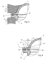
- FIG. 5 When closing the capsule, as in FIG. 5 shown very schematically, the main body collar supported from below by a first tool 21 (anvil) while the lid is placed, and from above, a second tool 22 (sonotrode) couples ultrasonic energy into the lid collar, so that welding takes place.
- FIG. 6 illustrates the location of the weld after disconnecting the supernatant.
- the area shown with cross-hatching illustrates the original position of the energy director 23; in reality, after the closure of the main body collar and the lid collar, they are also welded together next to this area.
- the circumferential collar forms a cover side facing surface 8, which extends from the Aussekante 7 of the collar to the projection 12 of the curvature.
- the projection 12 may be offset relative to the circumferential side wall formed by the base body 2 inwards.
- Such an offset v may be relevant in comparison to the thickness of the capsule wall; in particular, it is at least 0.2 mm.
- the offset v becomes as in FIG. 6 illustrated measured between the outer surface of the body in the region of the collar 4 parallel planes through the location of maximum concave curvature in the transition between the lid-side surface 8 and the base body surface 18 of the collar 4 and the curvature of the lid or the outer surface of the body go.
- the lid 8 forms between the Kragenbereicll and the actual top surface 9 a transition region 13, in which the wall has a curvature and thus forms the curvature.
- this goes from a lot, which is an almost right angle to the collar plane and the top surface 9, in a continuous convex curvature in the flat, the top surface forming area.
- the concave curvature is large (i.e., the radius of curvature) small.
- the concave and convex curvatures it would also be conceivable for the concave and convex curvatures to more closely match one another, which would then result in an S-shaped profile in cross-section.
- the areal restriction of the transition area ensures that the central flat area makes up a major part of the cover area (at least 40%) and therefore the cube or cuboid shape as a whole is not impaired.
- FIG. 6 visible is an optional thickening 14 in the transition between the circumferential side wall and the collar. Such a thickening serves the additional stiffening.
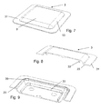
- Figures 7-9 show a cover not produced by thermoforming, but by injection molding 3.
- an inwardly projecting web 33 is formed. This serves as a mechanical stiffener and as a stacking aid.
- molded positioning projections 35 act in the region of the corners.
Abstract
Ein Verfahren zum Herstellen einer Kapsel weist die folgenden Schritte auf:
- Zur-Verfügung-stellen eines Grundkörpers (2) mit einem Bodenbereich (5), einer umlaufenden Seitenwand und einem an die umlaufende Seitenwand anschliessenden umlaufenden Grundkörper-Kragen (41), wobei der Grundkörper im Bereich des Grundkörper-Kragens (41) einen im Wesentlichen rechteckigen Querschnitt hat;
- Zur-Verfügung-stellen eines Deckels (3) zum Verschliessen der Kapsel, d.h. zum Bilden einer geschlossenen Kapsel mit dem Grundkörper (2) zusammen, wobei der Deckel (3) anschliessend an einen umlaufenden Deckel-Kragen (34) eine Wölbung nach aussen bildet, wobei der umlaufende Deckel-Kragen in seiner Dimensionierung auf den Grundkörper-Kragen (41) abgestimmt ist;
- Befüllen des Grundkörpers (2) mit einem Extraktionsgut; und
- Aufsetzen des Deckels (3) auf den Grundkörper (2), so, dass der Deckel-Kragen (34) auf dem Grundkörper-Kragen (41) aufliegt und Befestigen des Deckel-Kragens am Grundkörper-Kragen mittels Ultraschallschweissen,
- Wobei der Deckel (3) mit einem Energierichtungsgeber (23) versehen ist, der während des Ultraschallschweissens die Ultraschallenergie fokussiert.

- To make available a base body (2) having a bottom portion (5), a circumferential side wall and a peripheral side wall adjoining the circumferential base body collar (41), wherein the base body in the region of the main body collar (41) has an im Has substantially rectangular cross-section;
- Providing a cover (3) for closing the capsule, ie for forming a closed capsule with the base body (2) together, wherein the lid (3) subsequent to a circumferential cover collar (34) a curvature outwards forms, with the encircling cover collar is matched in its dimensions on the main body collar (41);
- filling the base body (2) with an extraction material; and
- placing the lid (3) on the base body (2), so that the lid collar (34) rests on the main body collar (41) and attaching the lid collar on the main body collar by means of ultrasonic welding,
- Wherein the lid (3) is provided with an energy directors (23), which focuses the ultrasound energy during the ultrasonic welding.
Description
Die Erfindung betrifft die Zubereitung von Getränken oder dergleichen aus einem in einer Kapsel enthaltenen Extraktionsgut, beispielsweise gemahlenem Kaffee. Sie betrifft insbesondere insbesondere ein Verfahren zum Herstellen einer mit einem Extraktionsgut gefüllten Kapsel sowie eine mit diesem Verfahren hergestellte Kapsel.The invention relates to the preparation of beverages or the like from an extraction material contained in a capsule, for example ground coffee. In particular, it relates in particular to a process for producing a capsule filled with an extraction material and to a capsule produced by this process.
Extraktionsgeräte zum Zubereiten von Getränken aus einem in einer Portionsverpackung vorhandenen Extraktionsgut sind beispielsweise als Kaffee-, Espresso- oder auch Teemaschinen bekannt und erfreuen sich nach wie vor steigender Beliebtheit. In vielen entsprechenden Systemen sind die Portionsverpackungen als Kapseln ausgebildet, in denen das Extraktionsgut bspw. luftdicht abgeschlossen ist. Für die Extraktion wird die Kapsel an zwei einander gegenüberliegenden Seiten angestochen. Auf der ersten Seite wird eine Brühflüssigkeit - im Allgemeinen heisses Wasser - eingeleitet. Auf der zweiten Seite wird das Brüherzeugnis aus der Kapsel ausgeleitet. Je nach zuzubereitendem Getränk und System muss dabei im Innern der Kapsel ein erheblicher Druck von beispielsweise 5-20 bar - für Filterkaffee oder Tee auch weniger - herrschen.Extraction devices for preparing beverages from an extraction material present in a portion packaging are known, for example, as coffee, espresso or tea machines and continue to enjoy increasing popularity. In many corresponding systems, the portion packages are designed as capsules, in which the extraction material, for example, is airtight. For extraction, the capsule is pierced on two opposite sides. On the first side, a brewing liquid - generally hot water - is introduced. On the second page, the brewing product is discharged from the capsule. Depending on the beverage and system to be prepared, a considerable pressure of, for example, 5-20 bar - for filter coffee or tea - must prevail inside the capsule.
Als Kapselmaterialien sind insbesondere Aluminium und Kunststoffe, bspw. Polypropylen bekannt geworden. Aluminiumkapseln bringen eine sehr gute Haltbarkeit (Aromaschutz) des Extraktionsguts, sind aber in der Herstellung sehr energieaufwändig. Polypropylenkapseln sind betreffend Energieaufwand und Entsorgung vorteilhaft, stellen aber erhöhte Anforderungen an den Anstechmechanismus und den Aromaschutz.As capsule materials in particular aluminum and plastics, for example. Polypropylene have become known. Aluminum capsules provide a very good durability (aroma protection) of the extraction material, but are very energy-consuming to produce. Polypropylene capsules are advantageous in terms of energy consumption and disposal, but make increased demands on the piercing mechanism and the aroma protection.
Aus der
Die Kapsel gemäss
Der vorliegenden Erfindung stellt sich demnach die Aufgabe, ein Verfahren zum Herstellen von Kapseln der in
Gemäss einem Aspekt der Erfindung weist ein Verfahren zum Herstellen einer Kapsel die folgenden Schritte auf:
- Zur-Verfügung-stellen eines Grundkörpers mit einem Bodenbereich, einer umlaufenden Seitenwand und einem an die umlaufende Seitenwand anschliessenden umlaufenden Grundkörper-Kragen, wobei der Grundkörper im Bereich des Kragens einen im Wesentlichen rechteckigen Querschnitt hat;
- Zur-Verfügung-stellen eines Deckels zum Verschliessen der Kapsel, d.h. zum Bilden einer geschlossenen Kapsel mit dem Grundkörper zusammen, wobei der Deckel anschliessend an einen umlaufenden Deckel-Kragen eine Wölbung nach aussen bildet, wobei der umlaufende Deckel-Kragen in seiner Dimensionierung auf den Grundkörper-Kragen abgestimmt ist;
- Befüllen des Grundkörpers mit einem Extraktionsgut; und
- Aufsetzen des Deckels auf den Grundkörper, so, dass der Deckel-Kragen auf dem Grundkörper-Kragen aufliegt und Befestigen des Deckel-Kragens am Grundkörper-Kragen mittels Ultraschallschweissen.
- To make available a base body having a bottom region, a circumferential side wall and a circumferential base body collar adjoining the circumferential side wall, the base body having a substantially rectangular cross section in the region of the collar;
- To provide a lid for closing the capsule, ie for forming a closed capsule together with the main body, wherein the lid then forms a curvature to the outside on a circumferential lid collar, wherein the encircling lid collar in its dimensioning on the Basic body collar is tuned;
- Filling the body with an extraction material; and
- Placing the lid on the body, so that the lid collar rests on the body collar and attaching the lid collar on the body collar by means of ultrasonic welding.
Das Verfahren zeichnet sich dadurch aus, dass der Deckel mit einem Energierichtungsgeber versehen ist, der während des Ultraschallschweissens die Ultraschallenergie fokussiert.The method is characterized in that the lid is provided with an energy director, which focuses the ultrasonic energy during the ultrasonic welding.
Eine mit einem solchen Verfahren herstellbare Kapsel mit einem Extraktionsgut weist auf:
- Einen Grundkörper mit einem Bodenbereich und einer umlaufenden Seitenwand; und
- einen am Grundkörper befestigten Deckel;
- wobei der Deckel entlang eines umlaufenden Kragens am Grundkörper befestigt ist, wobei der Kragen durch Ultraschall-Verschweissen eines zur Deckelseite hin an die umlaufende Seitenwand anschliessenden Grundkörper-Kragens und eines Deckel-Kragens hergestellt ist;
- wobei der Grundkörper im Bereich des Kragens einen im Wesentlichen rechteckigen Querschnitt hat;
- wobei der Deckel eine Wölbung nach aussen bildet, so dass der Deckel zu einem Kapselvolumen beiträgt;
- und wobei ein Energierichtungsgeber in den Deckel-Kragen integriert ist.
- A base body with a bottom portion and a circumferential side wall; and
- a lid attached to the body;
- wherein the lid is secured along a circumferential collar on the base body, wherein the collar is made by ultrasonic welding a to the lid side to the circumferential side wall subsequent base body collar and a lid collar;
- wherein the base body in the region of the collar has a substantially rectangular cross-section;
- wherein the lid forms a bulge outwardly, so that the lid contributes to a capsule volume;
- and wherein an energy director is integrated in the lid collar.
Energierichtungsgeber für Ultraschallschweissverfahren zum Verschliessen von Portionenkapseln sind längst bekannt und bspw. auch in der
Dies bringt unter anderem folgende Vorteile:
- Erstens hat sich gezeigt, dass sich ein Energierichtungsgeber am Deckel leichter herstellbar ist, insbesondere, wenn die Kapsel tiefgezogen ist. Es hat sich nämlich herausgestellt, dass es für das Tiefziehen eines Grundkörpers - zumal in der im Querschnitt rechteckigen Form - relativ herausfordernd ist, einen Energierichtungsgeber auf einem schmalen Kragen, nahe an der umlaufenden Seitenwand zu platzieren.
- First, it has been found that an energy director on the lid is easier to manufacture, especially when the capsule is deep-drawn. It has been found that it is relatively challenging for the deep drawing of a base body - especially in the rectangular in cross-section shape - to place an energy directors on a narrow collar, close to the peripheral side wall.
Mit dem vorgeschlagenen Vorgehen trägt die vorliegende Erfindung dazu bei, den Rand schmaler zu halten und damit bspw. die Stapelbarkeit und Kompaktheit der fertigen Kapsel zu verbessern.With the proposed approach, the present invention helps to keep the edge narrow and thus, for example, to improve the stackability and compactness of the finished capsule.
Zweitens hat sich gezeigt, dass das Ultraschallschweissen mindestens bei Kapseln der hier beschriebenen Art besser funktioniert, wenn der Energierichtungsgeber auf Seite der Sonotrode liegt. Aufgrund der Befüllung des Grundkörpers ist es jedoch nicht möglich, eine Sonotrode von unten, also vom Grundköper her, angreifen zu lassen. Die vorliegende Erfindung schafft hier durch Vorsehen des Energierichtungsgebers am Deckel Abhilfe.Second, it has been found that ultrasonic welding works better, at least for capsules of the type described here, when the energy director is on the side of the sonotrode. Due to the filling of the body, however, it is not possible to have a sonotrode attacked from below, ie from the parent body. The present invention provides a remedy by providing the energy director on the lid.
Die Form der Kapsel ist so, dass der Grundkörper im Bereich des Kragens im Querschnitt im Wesentlichen rechteckig, bspw. im Wesentlichen quadratisch ist. Auch der Kragen selbst - bspw. dessen Aussenkante - kann im Wesentlichen rechteckig, insbesondere quadratisch sein. ,Im Wesentlichen rechteckig' bzw. ,im Wesentlichen quadratisch' schliesst insbesondere abgerundete Ecken nicht aus.The shape of the capsule is such that the base body in the region of the collar in cross-section is substantially rectangular, for example substantially square. Also, the collar itself - for example, the outer edge - may be substantially rectangular, in particular square. "Substantially rectangular" or "substantially square" does not exclude in particular rounded corners.
Die Kapsel kann als Ganze - bis auf den Kragen und einen eventuellen Versatz der Deckelwölbung, siehe unten - die Form eines Würfels oder Quaders, insbesondere eines Würfels haben. In Ausführungsformen kann der Kragen seitlich mindestens 0.8 mm, insbesondere mindestens 1 mm und und/oder maximal 2 mm, insbesondere maximal 1.5 mm hervorstehen. Ein Vorteil dieser Dimensionierung (Breite zwischen 0.8 mm und 2 mm) ist, dass man hier den besten Kompromiss aus Stapelbarkeit / Kompaktheit (kleine Umverpackung) und zuverlässiger Versiegelung erhält. Ausserdem hilft der schmale Rand beim Führen und halten in eine Brüheinheit in der korrekte Orientierung, ohne dabei die Nachteile der bekannten grossen Krägen (Aussenvolumen und entsprechende Platzbeanspruchung in Verpackung und Brühheinheit; Optik) in Kauf zu nehmen. Das gilt unabhängig von den Dimensionen der Kapsel als Ganzer, d.h. die Dimensionierung des Kragens wird in Ausführungsformen für kleinere Kapseln genauso im genannten Bereich gewählt wie für grössere Kapseln.The capsule as a whole - except for the collar and a possible offset of the lid curl, see below - have the shape of a cube or cuboid, in particular a cube. In embodiments, the collar can protrude laterally at least 0.8 mm, in particular at least 1 mm and / or at most 2 mm, in particular at most 1.5 mm. An advantage of this dimensioning (width between 0.8 mm and 2 mm) is that it gives you the best compromise between stackability / compactness (small outer packaging) and reliable sealing. In addition, the narrow edge helps to guide and hold in a brewing unit in the correct orientation, without taking the disadvantages of the known large collars (external volume and corresponding space stress in packaging and brewing unit, optics) in purchasing. This is true regardless of the dimensions of the capsule as a whole, i. the dimensioning of the collar is chosen in embodiments for smaller capsules in the same range as for larger capsules.
Die Würfelform schliesst eine - bspw. bei tiefgezogenen Kapseln herstellungsbedingte - Neigung der umlaufenden Seitenflächen zur Achse (Senkrechten auf die Boden- und/oder Deckelfläche) von bspw. maximal 3°, insbesondere maximal 2° oder maximal 1.5° nicht aus.The cube shape excludes an inclination of the circumferential side surfaces to the axis (perpendicular to the bottom and / or top surface), for example in deep-drawn capsules of, for example, not more than 3 °, in particular not more than 2 ° or not more than 1.5 °.
Bei einer Ausführung im Wesentlichen in Würfelform beträgt die äussere Länge der Würfelkanten beispielsweise zwischen 24 und 30 mm für eine Füllmenge von zwischen ca. 6 g und ca. 10 g Kaffee. Für grössere Füllmengen sind auch grössere Abmessungen, bspw. von bis zu 35 mm, nicht ausgeschlossen.For example, in an essentially cube-shaped embodiment, the outer length of the cube edges is between 24 and 30 mm for a filling amount of between about 6 g and about 10 g of coffee. For larger quantities even larger dimensions, for example. Up to 35 mm, not excluded.
Der Grundkörper weist einen Bodenbereich und eine umlaufende Seitenwand auf und bildet so eine Art Becher, der durch den Deckel verschlossen wird. Dabei kann der Bodenbereich flach sein, das ist jedoch keine Notwendigkeit.The main body has a bottom portion and a circumferential side wall and thus forms a kind of cup, which is closed by the lid. The floor area can be flat, but this is not necessary.
Die Form des Deckels kann von aussen nach innen den Deckel-Kragen, einen gekrümmten Übergangsbereich und einen mittigen flachen Bereich aufweisen, der die eigentliche oberseitige Deckfläche bildet. Ein solcher flacher Bereich ist aufgrund des Übergangsbereichs, der die Wölbung bewirkt, von der Ebene des Deckel-Kragens nach aussen abgesetzt. Der Übergangsbereich kann bspw. S-förmig gekrümmt sein oder stetig von einer in einem Winkel zur Kragenebene stehenden äusseren Partie hin zum mittigen flachen Bereich gekrümmt verlaufen. Dabei ist die Dimensionierung beispielsweise so gewählt, dass der mittige flache Bereich optisch dominiert, indem er bspw. gleich gross wie oder nur unwesentlich (bspw. maximal 10%) kleiner als die Bodenfläche ist. Es kann insbesondere bei einer Ausführung der Kapsel als insgesamt quader- oder würfelförmig vorgesehen sein, dass dieser flache Bereich mehr als 60% des Durchmessers und entsprechend mindestens 40% der Fläche, einnimmt.The shape of the lid may have, from the outside inwards, the lid collar, a curved transition region and a central flat region which forms the actual top-side cover surface. Such a flat area is due to the transition region which causes the curvature, offset from the plane of the lid collar to the outside. The transition region can, for example, be curved in an S shape or extend continuously from an outer part standing at an angle to the collar plane to the central flat region curved. In this case, the dimensioning is chosen, for example, such that the central flat area optically dominates by being smaller than the floor area, for example, the same size as or only negligibly (for example, at most 10%). It may be provided in particular in one embodiment of the capsule as a total cuboid or cube-shaped that this flat area occupies more than 60% of the diameter and correspondingly at least 40% of the area.
Der Deckel-Kragen wird im Allgemeinen eine umlaufende, zur Deckelseite hin gewandte Fläche bilden, die sich von einer Aussenkante des Kragens bis zu einem Ansatz der Wölbung erstreckt. Es kann in Ausführungsformen vorgesehen sein, dass der Ansatz der Wölbung im Vergleich zu der Partie der Seitenwand, an welche der Kragen anschliesst, nach innen versetzt ist. Ein solcher Versatz kann bspw. mindestens 0.2 mm betragen.The lid collar will generally form a circumferential, lid-facing surface extending from an outer edge of the collar to a lug of the bulge. It may be provided in embodiments that the approach of the buckle is offset inwardly compared to the portion of the side wall to which the collar adjoins. Such an offset can be, for example, at least 0.2 mm.
Sowohl der Grundkörper als auch der Deckel sind im Allgemeinen aus Kunststoff gefertigt. Es kann insbesondere vorgesehen sein, dass Grundkörper und Deckel aus demselben Kunststoff bestehen. Als Beispiel für ein Material sei Polypropylen genannt, wobei eine Sperrschicht eingearbeitet sein kann, die eine Barriereneigenschaft für Sauerstoff hat und eine Diffusion von Sauerstoff in die Kapsel verhindert. Eine solche Sperrschicht weist bspw. ein Ethylen-Vinylalkohol-Copolymer (EVOH) auf. Die Wandstärke im Bereich des Grundkörpers beträgt insbesondere 0.1 mm und 0.7 mm, vorzugsweise zwischen 0.2 mm und 0.4 mm, bspw. zwischen 0.25 mm und 0.35 mm. Dasselbe kann auch für die Wandstärke des Deckels gelten. In einer Ausführungsform entspricht die Wandstärke des Deckels ungefähr der Wandstärke des Grundkörpers.Both the base body and the lid are generally made of plastic. It can be provided in particular that the base body and lid are made of the same plastic. As an example of a material is polypropylene called, wherein a barrier layer may be incorporated, which has a barrier property for oxygen and prevents diffusion of oxygen into the capsule. Such a barrier layer has, for example, an ethylene-vinyl alcohol copolymer (EVOH). The wall thickness in the region of the base body is in particular 0.1 mm and 0.7 mm, preferably between 0.2 mm and 0.4 mm, for example between 0.25 mm and 0.35 mm. The same can also apply to the wall thickness of the lid. In one embodiment, the wall thickness of the lid approximately corresponds to the wall thickness of the base body.
Anstelle von Polypropylen kommen auch andere Kunststoffe in Frage. Auch die Anwendung der Erfindung auf ultraschallverschweissbare Nicht-Kunststoffe ist nicht ausgeschlossen.Instead of polypropylene, other plastics come into question. The application of the invention to ultrasonically weldable non-plastics is not excluded.
Der Energierichtungsgeber kann wie an sich bekannt die Form einer Rippe haben, beispielsweise mit einem V-förmigen Profil. Eine solche Rippe kann parallel zum Kragenverlauf umlaufend angeordnet sein. Auch zwei oder mehr solcher Rippen können vorhanden sein; ein zum Kragen nicht-paralleler Verlauf ist - für eine oder mehrere Rippen - ebenfalls nicht ausgeschlossen. Auch andere Energierichtungsgeberformen sind denkbar, bspw. in der Form einer umlaufenden Anordnung von einzelnen hügelartigen Erhebungen etc.The energy director can, as is known, have the shape of a rib, for example a V-shaped profile. Such a rib may be arranged circumferentially parallel to the collar profile. Also, two or more such ribs may be present; a non-parallel to the collar course is - for one or more ribs - also not excluded. Other types of energy directors are also conceivable, for example in the form of a circumferential arrangement of individual hill-like elevations, etc.
Insbesondere wenn der Deckel durch Tiefziehen hergestellt ist (aufgrund von dessen beschränkter Tiefe kann das Tiefziehverfahren an diesem auch als Prägeverfahren aufgefasst werden), weist er im Bereich des Deckelkragens auf der Aussenseite, d.h. der vom Grundkörper abgewandten Seite, unter Umständen eine zum Energierichtungsgeber inverse Struktur auf, welche auch an der fertig hergestellten Kapsel noch sichtbar ist. Insbesondere kann eine solche Struktur eine umlaufende Nut aufweisen. Diese Struktur entsteht bei der Herstellung des Deckels im Tiefziehverfahren (bzw. dem Prägeverfahren), durch das Einprägen des Energierichtungsgebers, und kann beim Verschweissen der Kapsel auch als Zentrierhilfe dienen. So kann z.B. eine zu der Nut komplementäre umlaufende Rippe an der Sonotrode vorgesehen sein, mit deren Hilfe der Deckel dann auf der Kapsel zentriert werden kann.In particular, when the lid is made by deep drawing (due to its limited depth, the deep-drawing process can be considered as this embossing process), he has in the region of the lid collar on the outside, ie the side facing away from the base body, under certain circumstances, an energy directors inverse structure on, which is still visible on the finished capsule. In particular, such a structure may have a circumferential groove. This structure arises in the manufacture of the lid in Deep-drawing process (or the embossing process), by impressing the energy directors, and can also serve as a centering when welding the capsule. Thus, for example, a groove complementary to the circumferential rib may be provided on the sonotrode, with the aid of which the lid can then be centered on the capsule.
Anstelle eines Tiefziehverfahrens kommt für die Herstellung des Deckels auch ein Spritzgiessverfahren in Frage.Instead of a deep drawing process, an injection molding process is also suitable for the production of the lid.
Auch der Grundkörper kann im Tiefziehverfahren oder alternativ durch Spritzgiessen hergestellt sein. Im Allgemeinen werden entweder Grundkörper und Deckel beide je tiefgezogen oder spritzgegossen sein, aber auch Kombinationen mit spritzgegossenem Grundkörper und tiefgezogenem Deckel und umgekehrt sind möglich.Also, the main body can be made by deep drawing or alternatively by injection molding. In general, either base body and lid are both ever deep-drawn or injection-molded, but also combinations with injection-molded body and deep-drawn lid and vice versa are possible.
Der Grundkörper-Kragen und/oder der Deckel-Kragen kann/können mit einem Übermass zur Verfügung gestellt werden. Anschliessend an das Verschweissen oder gleichzeitig mit dem Verschweissen werden die überstehenden Bereiche dann abgetrennt, bspw. durch Ultraschall oder durch Stanzen.The main body collar and / or the lid collar can be provided with an oversize. Following the welding or simultaneously with the welding, the protruding areas are then separated, for example by ultrasound or by punching.
In Ausführungsformen kann der Deckel oder der Grundkörper, insbesondere aber der Deckel, mit einer Positionierungshilfe versehen sein. Eine solche kann insbesondere einen über die Ebene, in welcher der Grundkörper-Kragen und der Deckel-Kragen aneinander stossen, hinaus ragenden Vorsprung aufweisen. Gemäss einer ersten Ausführungsform wird eine Positionierungshilfe durch eine Schulter in einem Bereich des Deckel-Kragens oder des Grundkörper-Kragens gebildet, wobei der Bereich mit der Schulter anschliessend abgetrennt wird. Eine solche Schulter kann mit dem Grundkörper-Kragen bzw. dem Deckel-Kragen zusammenwirken, um den Deckel relativ zum Grundkörper auszurichten, wenn der Deckel platziert wird. Eine solche Schulter ist insbesondere bei Fertigung durch Tiefziehen günstig, da sie einfach herstellbar ist. Gemäss einer zweiten Ausführungsform kann eine Positionierungshilfe einen nach innen ragenden Positionierungsvorsprung aufweisen, der im Innern des Kapselvolumens angeordnet ist und ebenfalls den Deckel relativ zum Grundkörper ausrichtet. Ein solcher Vorsprung kann insbesondere bei einer Fertigung durch Spritzgiessen angebracht werden.In embodiments, the cover or the main body, but in particular the lid, be provided with a positioning aid. Such may, in particular, have a protrusion projecting beyond the plane in which the main body collar and the lid collar abut each other. According to a first embodiment, a positioning aid is formed by a shoulder in a region of the cover collar or of the main body collar, the region with the shoulder subsequently being severed. Such a shoulder can cooperate with the main body collar or the lid collar to align the lid relative to the base body when the lid is placed. Such a shoulder is particularly low in production by deep drawing, since it is easy to produce. According to a second embodiment, a positioning aid can have an inwardly projecting positioning projection, which is arranged inside the capsule volume and also aligns the lid relative to the main body. Such a projection can be attached in particular during production by injection molding.
Eine solche Positionierungshilfe dient in Ausführungsformen nicht nur der Ausrichtung des Deckels relativ zum Grundkörper, sondern auch der besseren Stapelbarkeit einer Vielzahl von Deckeln nach deren Fertigung.Such positioning aid is used in embodiments not only the orientation of the lid relative to the base body, but also the better stackability of a plurality of lids after their production.
Ausführungsbeispiele der Erfindung werden nachfolgend anhand von Zeichnungen beschrieben. In den Zeichnungen bezeichnen gleiche Bezugszeichen gleiche oder analoge Elemente. Die Zeichnungen sind nicht massstäblich und zeigen teilweise einander entsprechende Elemente in von Figur zu Figur unterschiedlichen Grössen. Es zeigen:
-
Fig. 1 eine Kapsel; -
Fig. 2 einen Grundkörper für die Herstellung einer Kapsel gemässFig. 1 ; -
Fig. 3 einen Deckel für die Herstellung der Kapsel; -
Fig. 4 den Deckel gemässFig. 3 , angeschnitten gezeichnet; -
Fig. 5 und 6 je eine Schnittdarstellung eines Details der Kapsel gemässFig. 4 im Bereich des Kragens; -
Fig. 7 einen weiteren Deckel; -
Fig. 8 den Deckel gemässFig. 7 , angeschnitten gezeichnet; und -
Fig. 9 eine Unteransicht des Deckels gemässFig. 7 , ebenfalls angeschnitten dargestellt.
-
Fig. 1 a capsule; -
Fig. 2 a basic body for the preparation of a capsule according toFig. 1 ; -
Fig. 3 a lid for the production of the capsule; -
Fig. 4 the lid according toFig. 3 drawn with a cut; -
FIGS. 5 and 6 each a sectional view of a detail of the capsule according toFig. 4 in the area of the collar; -
Fig. 7 another lid; -
Fig. 8 the lid according toFig. 7 drawn with a cut; and -
Fig. 9 a bottom view of the lid according toFig. 7 , also shown cut.
Die Kapsel 1 gemäss
Die Kapsel weist einen Grundkörper (oder Becher) 2 und einen entlang eines umlaufenden Kragens 4 daran befestigten Deckel 3 auf. Der Grundkörper bildet einen Kapselboden 5 und eine umlaufende Seitenwand 6, welche an ihrem in Bezug auf axiale Richtungen (Achse 10) äusseren, in der Figur oberen, Ende durch den Kragen 4 abgeschlossen wird. Der Deckel ist nach aussen gewölbt, indem die zum Kapselboden 5 im Wesentlichen parallele Deckelfläche 9 im Vergleich zum umlaufenden Kragen 4 nach aussen versetzt ist.The capsule has a base body (or cup) 2 and a
Bei der Kapselherstellung wird zunächst der Grundkörper 2 mit dem Extraktionsgut befüllt, und anschliessend wird der Deckel 3 positioniert.
Der Deckel weist einen seitlichen Überstand 31 auf, der bei oder nach der Befestigung am Grundkörper abgetrennt wird. Am Überstand ist ein abgesetzter Bereich vorhanden, so dass eine Schulter 32 gebildet wird. Der Deckel ist so dimensioniert, dass der Grundkörper-Kragen 41 bis zu dieser Schulter reicht, wenn der Deckel auf dem Grundkörper positioniert wird, so dass die Schulter als Hilfe bei der Positionierung relativ zum Grundkörper dient.The lid has a
Beim Verschliessen der Kapsel wird, wie in
Der umlaufende Kragen bildet eine zu Deckelseite hin gewandte Fläche 8, die sich von der Aussekante 7 des Kragens bis zum Ansatz 12 der Wölbung erstreckt. Wie man in
Der Deckel 8 bildet zwischen dem Kragenbereicll und der eigentlichen Deckfläche 9 einen Übergangsbereich 13, in welchem die Wand eine Krümmung aufweist und so die Wölbung bildet. Im gezeichneten Beispiel geht dieser ausgehend von einer Partie, die einem fast rechten Winkel zur Kragenebene und der Deckfläche 9 steht, in stetiger konvexer Krümmung in den flachen, die Deckfläche bildenden Bereich über. Am Ansatz 12 ist daher die konkave Krümmung gross (d.h. der Krümmungsradius) klein. Es wäre aber auch denkbar, die konkave und die konvexe Krümmung einander mehr anzugleichen, wodurch dann ein im Querschnitt S-förmiger Verlauf resultieren würde. Durch die flächenmässige Beschränkung des Übergangsbereichs ist gewährleistet, dass der mittige flache Bereich einen Grossteil der Deckelfläche (mindestens 40%) ausmacht und daher die Würfel- oder Quaderform als Ganze nicht beeinträchtigt ist.The
Ebenfalls in
Claims (15)
Priority Applications (19)
| Application Number | Priority Date | Filing Date | Title |
|---|---|---|---|
| EP13199515.1A EP2889224B1 (en) | 2013-12-24 | 2013-12-24 | Portion capsule for preparing a brewed product and method for producing the same |
| PL13199515T PL2889224T3 (en) | 2013-12-24 | 2013-12-24 | Portion capsule for preparing a brewed product and method for producing the same |
| ES13199515.1T ES2572682T3 (en) | 2013-12-24 | 2013-12-24 | Ration capsules for the preparation of a scalded product and procedure for its manufacture |
| DK13199515.1T DK2889224T3 (en) | 2013-12-24 | 2013-12-24 | Serving capsule for preparing a brewing product and method for making it |
| HUE13199515A HUE028613T2 (en) | 2013-12-24 | 2013-12-24 | Portion capsule for preparing a brewed product and method for producing the same |
| BR112016014918-1A BR112016014918B1 (en) | 2013-12-24 | 2014-12-11 | METHOD FOR MANUFACTURING DOSE CAPSULE AND DOSE CAPSULE |
| KR1020167020213A KR102394744B1 (en) | 2013-12-24 | 2014-12-11 | Portion capsule for preparing a brewed product and method for producing said portion capsule |
| AU2014372756A AU2014372756B2 (en) | 2013-12-24 | 2014-12-11 | Portion capsule for preparing a brewed product and method for producing said portion capsule |
| SG11201605142XA SG11201605142XA (en) | 2013-12-24 | 2014-12-11 | Portion capsule for preparing a brewed product and method for producing said portion capsule |
| CA2934746A CA2934746C (en) | 2013-12-24 | 2014-12-11 | Portion capsule for preparing a brewed product and a method for producing said portion capsule |
| US15/104,441 US9957102B2 (en) | 2013-12-24 | 2014-12-11 | Portion capsule for preparing a brewed product and a method for producing said portion capsule |
| RU2016129303A RU2664314C2 (en) | 2013-12-24 | 2014-12-11 | Portion capsule for preparation of brewed product and method of its manufacture |
| CN201480070631.9A CN106061848B (en) | 2013-12-24 | 2014-12-11 | It is used to prepare the portioning capsule and its manufacturing method for brewing product |
| JP2016542719A JP6545689B2 (en) | 2013-12-24 | 2014-12-11 | Portion capsules for making an extract product and method for manufacturing the portion capsules |
| PCT/EP2014/077351 WO2015096990A1 (en) | 2013-12-24 | 2014-12-11 | Portion capsule for preparing a brewed product and method for producing said portion capsule |
| MX2016008412A MX2016008412A (en) | 2013-12-24 | 2014-12-11 | Portion capsule for preparing a brewed product and method for producing said portion capsule. |
| IL246200A IL246200B (en) | 2013-12-24 | 2016-06-14 | Portion capsule for preparing a brewed product and method for producing said portion capsule |
| CL2016001626A CL2016001626A1 (en) | 2013-12-24 | 2016-06-23 | Mono-portion capsule to prepare an elaborated products and a method to produce said mono-portion capsule with a cap with a groove that is peripheral on an outer side, in a region of the cap collar with an energy director that centers the ultrasonic energy during ultrasonic welding. |
| ZA2016/04607A ZA201604607B (en) | 2013-12-24 | 2016-07-06 | Portion capsule for preparing a brewed product and method for producing said portion capsule |
Applications Claiming Priority (1)
| Application Number | Priority Date | Filing Date | Title |
|---|---|---|---|
| EP13199515.1A EP2889224B1 (en) | 2013-12-24 | 2013-12-24 | Portion capsule for preparing a brewed product and method for producing the same |
Publications (2)
| Publication Number | Publication Date |
|---|---|
| EP2889224A1 true EP2889224A1 (en) | 2015-07-01 |
| EP2889224B1 EP2889224B1 (en) | 2016-02-24 |
Family
ID=49880613
Family Applications (1)
| Application Number | Title | Priority Date | Filing Date |
|---|---|---|---|
| EP13199515.1A Active EP2889224B1 (en) | 2013-12-24 | 2013-12-24 | Portion capsule for preparing a brewed product and method for producing the same |
Country Status (19)
| Country | Link |
|---|---|
| US (1) | US9957102B2 (en) |
| EP (1) | EP2889224B1 (en) |
| JP (1) | JP6545689B2 (en) |
| KR (1) | KR102394744B1 (en) |
| CN (1) | CN106061848B (en) |
| AU (1) | AU2014372756B2 (en) |
| BR (1) | BR112016014918B1 (en) |
| CA (1) | CA2934746C (en) |
| CL (1) | CL2016001626A1 (en) |
| DK (1) | DK2889224T3 (en) |
| ES (1) | ES2572682T3 (en) |
| HU (1) | HUE028613T2 (en) |
| IL (1) | IL246200B (en) |
| MX (1) | MX2016008412A (en) |
| PL (1) | PL2889224T3 (en) |
| RU (1) | RU2664314C2 (en) |
| SG (1) | SG11201605142XA (en) |
| WO (1) | WO2015096990A1 (en) |
| ZA (1) | ZA201604607B (en) |
Families Citing this family (12)
| Publication number | Priority date | Publication date | Assignee | Title |
|---|---|---|---|---|
| EP3031749A1 (en) | 2014-12-11 | 2016-06-15 | Qbo Coffee GmbH | Beverage capsule, beverage preparation system and method for identifying a beverage capsule |
| EP3031748A1 (en) | 2014-12-11 | 2016-06-15 | Qbo Coffee GmbH | Beverage capsule, beverage preparation system and method for identifying a beverage capsule |
| EP3031750A1 (en) | 2014-12-11 | 2016-06-15 | Qbo Coffee GmbH | Beverage capsule, beverage preparation system and method for identifying a beverage capsule |
| JP6888399B2 (en) * | 2017-04-28 | 2021-06-16 | 凸版印刷株式会社 | Paper container and its manufacturing method |
| ES2929995T3 (en) * | 2018-07-27 | 2022-12-05 | Gcs German Capsule Solution Gmbh | Procedure for the manufacture of a single-dose capsule for the preparation of a beverage in a beverage preparation machine |
| US20220227574A1 (en) * | 2020-01-30 | 2022-07-21 | Sung Oh | Draining the Beverage From a Single-Serve Beverage Pod With or Without an Outlet Piercing Element |
| EP3907157A1 (en) * | 2020-05-08 | 2021-11-10 | Tchibo GmbH | Composite material comprising a component obtained from silverskins of coffee berries and a cartridge comprising this composite material |
| EP3907158A1 (en) * | 2020-05-08 | 2021-11-10 | Tchibo GmbH | Cartridge and method for producing a cartridge |
| EP3907145A1 (en) | 2020-05-08 | 2021-11-10 | Tchibo GmbH | Portion capsule and method for manufacturing a portion capsule |
| US20220234772A1 (en) * | 2021-01-06 | 2022-07-28 | Nexe Innovations Inc. | Method of sealing a compostable container by piercing the lidding |
| EP4173978A1 (en) | 2021-10-27 | 2023-05-03 | Tchibo GmbH | Method and device for producing a portion capsule |
| EP4209431A1 (en) | 2022-01-11 | 2023-07-12 | Tchibo GmbH | Portion capsule |
Citations (3)
| Publication number | Priority date | Publication date | Assignee | Title |
|---|---|---|---|---|
| US20090007793A1 (en) * | 2007-07-02 | 2009-01-08 | Appliance Development Corporation | Infusible material capsule for brewing a beverage |
| WO2010118543A1 (en) * | 2009-04-15 | 2010-10-21 | Luna Technology Systems Lts Gmbh | Capsule for an extraction product, method for the production thereof, and device for brewing coffee |
| EP2465793A1 (en) * | 2010-12-20 | 2012-06-20 | Macchiavelli S.r.l. | Capsule for infusion products |
Family Cites Families (12)
| Publication number | Priority date | Publication date | Assignee | Title |
|---|---|---|---|---|
| JPH0176406U (en) * | 1987-11-06 | 1989-05-23 | ||
| JP2000128130A (en) * | 1998-10-26 | 2000-05-09 | Shikoku Kakoki Co Ltd | Ultrasonic-sealed container |
| CN2473159Y (en) * | 2001-02-07 | 2002-01-23 | 安捷企业有限公司 | Synthetic resin container sealed by sealing machine |
| CA2688378C (en) * | 2007-06-05 | 2017-03-07 | Nestec S.A. | Single-use capsule for preparing a food liquid by centrifugation |
| ATE504228T1 (en) * | 2007-06-05 | 2011-04-15 | Nestec Sa | METHOD FOR PRODUCING A DRINK OR LIQUID FOOD |
| RU2527176C2 (en) * | 2008-12-09 | 2014-08-27 | Нестек С.А. | Capsule for beverage preparation by centrifugation method and beverage preparation device |
| EP2236437B1 (en) * | 2009-03-31 | 2012-03-21 | Nestec S.A. | Capsule with filter for preparing a liquid nutritional or food composition and related beverage production system |
| EP2384996A1 (en) * | 2010-05-04 | 2011-11-09 | Luna Technology Systems LTS GmbH | Capsule for coffee, method for its production and device for brewing coffee |
| DE202010007919U1 (en) * | 2010-06-12 | 2010-11-11 | Mahlich, David | Portion capsule for powdered or liquid beverage base materials |
| PT2624731E (en) * | 2010-10-08 | 2015-12-07 | Qbo Coffee Gmbh | Extraction device and sealing system |
| WO2013157924A1 (en) * | 2012-04-17 | 2013-10-24 | Biserkon Holdings Ltd. | Capsule and device for preparing beverages and method for manufacturing a capsule |
| CA2872931C (en) * | 2012-05-16 | 2019-03-12 | Nestec S.A. | Beverage capsule for centrifugal extraction |
-
2013
- 2013-12-24 EP EP13199515.1A patent/EP2889224B1/en active Active
- 2013-12-24 HU HUE13199515A patent/HUE028613T2/en unknown
- 2013-12-24 ES ES13199515.1T patent/ES2572682T3/en active Active
- 2013-12-24 DK DK13199515.1T patent/DK2889224T3/en active
- 2013-12-24 PL PL13199515T patent/PL2889224T3/en unknown
-
2014
- 2014-12-11 KR KR1020167020213A patent/KR102394744B1/en active IP Right Grant
- 2014-12-11 CA CA2934746A patent/CA2934746C/en active Active
- 2014-12-11 JP JP2016542719A patent/JP6545689B2/en active Active
- 2014-12-11 WO PCT/EP2014/077351 patent/WO2015096990A1/en active Application Filing
- 2014-12-11 SG SG11201605142XA patent/SG11201605142XA/en unknown
- 2014-12-11 CN CN201480070631.9A patent/CN106061848B/en active Active
- 2014-12-11 MX MX2016008412A patent/MX2016008412A/en active IP Right Grant
- 2014-12-11 BR BR112016014918-1A patent/BR112016014918B1/en active IP Right Grant
- 2014-12-11 RU RU2016129303A patent/RU2664314C2/en active
- 2014-12-11 US US15/104,441 patent/US9957102B2/en active Active
- 2014-12-11 AU AU2014372756A patent/AU2014372756B2/en active Active
-
2016
- 2016-06-14 IL IL246200A patent/IL246200B/en not_active IP Right Cessation
- 2016-06-23 CL CL2016001626A patent/CL2016001626A1/en unknown
- 2016-07-06 ZA ZA2016/04607A patent/ZA201604607B/en unknown
Patent Citations (3)
| Publication number | Priority date | Publication date | Assignee | Title |
|---|---|---|---|---|
| US20090007793A1 (en) * | 2007-07-02 | 2009-01-08 | Appliance Development Corporation | Infusible material capsule for brewing a beverage |
| WO2010118543A1 (en) * | 2009-04-15 | 2010-10-21 | Luna Technology Systems Lts Gmbh | Capsule for an extraction product, method for the production thereof, and device for brewing coffee |
| EP2465793A1 (en) * | 2010-12-20 | 2012-06-20 | Macchiavelli S.r.l. | Capsule for infusion products |
Also Published As
| Publication number | Publication date |
|---|---|
| HUE028613T2 (en) | 2016-12-28 |
| BR112016014918B1 (en) | 2021-04-06 |
| CL2016001626A1 (en) | 2017-05-12 |
| MX2016008412A (en) | 2017-01-11 |
| RU2016129303A3 (en) | 2018-06-15 |
| CA2934746C (en) | 2022-06-07 |
| RU2016129303A (en) | 2018-01-30 |
| KR20160108371A (en) | 2016-09-19 |
| CA2934746A1 (en) | 2015-07-02 |
| US20160325862A1 (en) | 2016-11-10 |
| ES2572682T3 (en) | 2016-06-01 |
| BR112016014918A2 (en) | 2017-08-08 |
| CN106061848B (en) | 2019-05-17 |
| DK2889224T3 (en) | 2016-05-09 |
| WO2015096990A1 (en) | 2015-07-02 |
| JP2017508674A (en) | 2017-03-30 |
| EP2889224B1 (en) | 2016-02-24 |
| CN106061848A (en) | 2016-10-26 |
| PL2889224T3 (en) | 2016-08-31 |
| AU2014372756A1 (en) | 2016-07-07 |
| ZA201604607B (en) | 2017-11-29 |
| KR102394744B1 (en) | 2022-05-04 |
| IL246200A0 (en) | 2016-07-31 |
| RU2664314C2 (en) | 2018-08-16 |
| SG11201605142XA (en) | 2016-08-30 |
| AU2014372756B2 (en) | 2019-06-27 |
| JP6545689B2 (en) | 2019-07-17 |
| IL246200B (en) | 2020-05-31 |
| US9957102B2 (en) | 2018-05-01 |
Similar Documents
| Publication | Publication Date | Title |
|---|---|---|
| EP2889224B1 (en) | Portion capsule for preparing a brewed product and method for producing the same | |
| EP2986514B1 (en) | Portion capsule for preparing a brewed product | |
| EP2647317B1 (en) | Method and preparation system for preparing a brewed product | |
| EP2566784B1 (en) | Capsule for an extraction beverage and device for preparing a beverage | |
| EP2687461B1 (en) | Apparatus for brewing coffee | |
| EP2053950B1 (en) | Means for penetrating portion packaging containing extractable material, device for extracting the extractable material contained in the portion packaging, and method for the production of said means | |
| EP2986515B1 (en) | Portion capsule for preparing a brewed product | |
| DE202014011368U1 (en) | Beverage manufacturing system and capsule for making a beverage | |
| EP3261957B1 (en) | Capsule with a sealed filter element | |
| EP3322651B1 (en) | Filter element having a cut-out | |
| EP3487787A1 (en) | Capsule and method for producing a plurality of capsules | |
| EP3924270B1 (en) | Single-serve capsule for preparing a beverage in a beverage preparation machine, and system for preparing a beverage from said single-serve capsule | |
| CH710252A1 (en) | Coffee capsule. | |
| WO2021224421A1 (en) | Method for producing a single-serve capsule, and single-serve capsule | |
| WO2022038082A1 (en) | Single-serve capsule main body and single-serve capsule for a beverage preparation machine and associated method | |
| WO2023135137A1 (en) | Portion capsule | |
| EP4368536A1 (en) | Portion capsule | |
| AT507739B1 (en) | METHOD FOR PRODUCING A COMBI PACKAGING CONTAINER | |
| EP0754145A1 (en) | Packaging container for free-flowing materials, and method and device for manufacturing the container |
Legal Events
| Date | Code | Title | Description |
|---|---|---|---|
| PUAI | Public reference made under article 153(3) epc to a published international application that has entered the european phase |
Free format text: ORIGINAL CODE: 0009012 |
|
| 17P | Request for examination filed |
Effective date: 20140818 |
|
| AK | Designated contracting states |
Kind code of ref document: A1 Designated state(s): AL AT BE BG CH CY CZ DE DK EE ES FI FR GB GR HR HU IE IS IT LI LT LU LV MC MK MT NL NO PL PT RO RS SE SI SK SM TR |
|
| AX | Request for extension of the european patent |
Extension state: BA ME |
|
| GRAP | Despatch of communication of intention to grant a patent |
Free format text: ORIGINAL CODE: EPIDOSNIGR1 |
|
| INTG | Intention to grant announced |
Effective date: 20150731 |
|
| RAP1 | Party data changed (applicant data changed or rights of an application transferred) |
Owner name: QBO COFFEE GMBH |
|
| GRAS | Grant fee paid |
Free format text: ORIGINAL CODE: EPIDOSNIGR3 |
|
| RBV | Designated contracting states (corrected) |
Designated state(s): AL AT BE BG CH CY CZ DE DK EE ES FI FR GB GR HR HU IE IS IT LI LT LU LV MC MK MT NL NO PL PT RO RS SE SI SK SM TR |
|
| GRAA | (expected) grant |
Free format text: ORIGINAL CODE: 0009210 |
|
| AK | Designated contracting states |
Kind code of ref document: B1 Designated state(s): AL AT BE BG CH CY CZ DE DK EE ES FI FR GB GR HR HU IE IS IT LI LT LU LV MC MK MT NL NO PL PT RO RS SE SI SK SM TR |
|
| REG | Reference to a national code |
Ref country code: GB Ref legal event code: FG4D Free format text: NOT ENGLISH |
|
| REG | Reference to a national code |
Ref country code: CH Ref legal event code: EP |
|
| REG | Reference to a national code |
Ref country code: AT Ref legal event code: REF Ref document number: 776543 Country of ref document: AT Kind code of ref document: T Effective date: 20160315 |
|
| REG | Reference to a national code |
Ref country code: IE Ref legal event code: FG4D Free format text: LANGUAGE OF EP DOCUMENT: GERMAN |
|
| REG | Reference to a national code |
Ref country code: DE Ref legal event code: R096 Ref document number: 502013001994 Country of ref document: DE |
|
| REG | Reference to a national code |
Ref country code: DK Ref legal event code: T3 Effective date: 20160504 |
|
| REG | Reference to a national code |
Ref country code: CH Ref legal event code: NV Representative=s name: FREI PATENTANWALTSBUERO AG, CH |
|
| REG | Reference to a national code |
Ref country code: SE Ref legal event code: TRGR |
|
| REG | Reference to a national code |
Ref country code: RO Ref legal event code: EPE |
|
| REG | Reference to a national code |
Ref country code: PT Ref legal event code: SC4A Free format text: AVAILABILITY OF NATIONAL TRANSLATION Effective date: 20160524 |
|
| REG | Reference to a national code |
Ref country code: ES Ref legal event code: FG2A Ref document number: 2572682 Country of ref document: ES Kind code of ref document: T3 Effective date: 20160601 Ref country code: NL Ref legal event code: FP |
|
| REG | Reference to a national code |
Ref country code: EE Ref legal event code: FG4A Ref document number: E011907 Country of ref document: EE Effective date: 20160516 |
|
| REG | Reference to a national code |
Ref country code: NO Ref legal event code: T2 Effective date: 20160224 |
|
| PG25 | Lapsed in a contracting state [announced via postgrant information from national office to epo] |
Ref country code: HR Free format text: LAPSE BECAUSE OF FAILURE TO SUBMIT A TRANSLATION OF THE DESCRIPTION OR TO PAY THE FEE WITHIN THE PRESCRIBED TIME-LIMIT Effective date: 20160224 |
|
| PG25 | Lapsed in a contracting state [announced via postgrant information from national office to epo] |
Ref country code: RS Free format text: LAPSE BECAUSE OF FAILURE TO SUBMIT A TRANSLATION OF THE DESCRIPTION OR TO PAY THE FEE WITHIN THE PRESCRIBED TIME-LIMIT Effective date: 20160224 |
|
| REG | Reference to a national code |
Ref country code: SK Ref legal event code: T3 Ref document number: E 20996 Country of ref document: SK |
|
| REG | Reference to a national code |
Ref country code: GR Ref legal event code: EP Ref document number: 20160400879 Country of ref document: GR Effective date: 20160628 |
|
| REG | Reference to a national code |
Ref country code: DE Ref legal event code: R097 Ref document number: 502013001994 Country of ref document: DE |
|
| PG25 | Lapsed in a contracting state [announced via postgrant information from national office to epo] |
Ref country code: SM Free format text: LAPSE BECAUSE OF FAILURE TO SUBMIT A TRANSLATION OF THE DESCRIPTION OR TO PAY THE FEE WITHIN THE PRESCRIBED TIME-LIMIT Effective date: 20160224 |
|
| REG | Reference to a national code |
Ref country code: FR Ref legal event code: PLFP Year of fee payment: 4 |
|
| REG | Reference to a national code |
Ref country code: HU Ref legal event code: AG4A Ref document number: E028613 Country of ref document: HU |
|
| PLBE | No opposition filed within time limit |
Free format text: ORIGINAL CODE: 0009261 |
|
| STAA | Information on the status of an ep patent application or granted ep patent |
Free format text: STATUS: NO OPPOSITION FILED WITHIN TIME LIMIT |
|
| 26N | No opposition filed |
Effective date: 20161125 |
|
| PG25 | Lapsed in a contracting state [announced via postgrant information from national office to epo] |
Ref country code: SI Free format text: LAPSE BECAUSE OF FAILURE TO SUBMIT A TRANSLATION OF THE DESCRIPTION OR TO PAY THE FEE WITHIN THE PRESCRIBED TIME-LIMIT Effective date: 20160224 |
|
| PG25 | Lapsed in a contracting state [announced via postgrant information from national office to epo] |
Ref country code: MC Free format text: LAPSE BECAUSE OF FAILURE TO SUBMIT A TRANSLATION OF THE DESCRIPTION OR TO PAY THE FEE WITHIN THE PRESCRIBED TIME-LIMIT Effective date: 20160224 |
|
| PG25 | Lapsed in a contracting state [announced via postgrant information from national office to epo] |
Ref country code: LU Free format text: LAPSE BECAUSE OF NON-PAYMENT OF DUE FEES Effective date: 20161224 |
|
| REG | Reference to a national code |
Ref country code: FR Ref legal event code: PLFP Year of fee payment: 5 |
|
| PG25 | Lapsed in a contracting state [announced via postgrant information from national office to epo] |
Ref country code: IS Free format text: LAPSE BECAUSE OF FAILURE TO SUBMIT A TRANSLATION OF THE DESCRIPTION OR TO PAY THE FEE WITHIN THE PRESCRIBED TIME-LIMIT Effective date: 20160224 Ref country code: MK Free format text: LAPSE BECAUSE OF FAILURE TO SUBMIT A TRANSLATION OF THE DESCRIPTION OR TO PAY THE FEE WITHIN THE PRESCRIBED TIME-LIMIT Effective date: 20160224 Ref country code: CY Free format text: LAPSE BECAUSE OF FAILURE TO SUBMIT A TRANSLATION OF THE DESCRIPTION OR TO PAY THE FEE WITHIN THE PRESCRIBED TIME-LIMIT Effective date: 20160224 |
|
| PG25 | Lapsed in a contracting state [announced via postgrant information from national office to epo] |
Ref country code: MT Free format text: LAPSE BECAUSE OF FAILURE TO SUBMIT A TRANSLATION OF THE DESCRIPTION OR TO PAY THE FEE WITHIN THE PRESCRIBED TIME-LIMIT Effective date: 20160224 |
|
| PG25 | Lapsed in a contracting state [announced via postgrant information from national office to epo] |
Ref country code: AL Free format text: LAPSE BECAUSE OF FAILURE TO SUBMIT A TRANSLATION OF THE DESCRIPTION OR TO PAY THE FEE WITHIN THE PRESCRIBED TIME-LIMIT Effective date: 20160224 |
|
| REG | Reference to a national code |
Ref country code: CH Ref legal event code: PCAR Free format text: NEW ADDRESS: POSTFACH, 8032 ZUERICH (CH) |
|
| REG | Reference to a national code |
Ref country code: EE Ref legal event code: HC1A Ref document number: E011907 Country of ref document: EE |
|
| PGFP | Annual fee paid to national office [announced via postgrant information from national office to epo] |
Ref country code: TR Payment date: 20221223 Year of fee payment: 10 Ref country code: ES Payment date: 20230227 Year of fee payment: 10 Ref country code: CH Payment date: 20230101 Year of fee payment: 10 |
|
| P01 | Opt-out of the competence of the unified patent court (upc) registered |
Effective date: 20230529 |
|
| PGFP | Annual fee paid to national office [announced via postgrant information from national office to epo] |
Ref country code: SK Payment date: 20231222 Year of fee payment: 11 |
|
| PGFP | Annual fee paid to national office [announced via postgrant information from national office to epo] |
Ref country code: GR Payment date: 20231221 Year of fee payment: 11 Ref country code: GB Payment date: 20231220 Year of fee payment: 11 |
|
| PGFP | Annual fee paid to national office [announced via postgrant information from national office to epo] |
Ref country code: SE Payment date: 20231220 Year of fee payment: 11 Ref country code: RO Payment date: 20231214 Year of fee payment: 11 Ref country code: PT Payment date: 20231214 Year of fee payment: 11 Ref country code: NO Payment date: 20231222 Year of fee payment: 11 Ref country code: NL Payment date: 20231220 Year of fee payment: 11 Ref country code: LV Payment date: 20231222 Year of fee payment: 11 Ref country code: LT Payment date: 20231123 Year of fee payment: 11 Ref country code: IT Payment date: 20231228 Year of fee payment: 11 Ref country code: IE Payment date: 20231220 Year of fee payment: 11 Ref country code: HU Payment date: 20231222 Year of fee payment: 11 Ref country code: FR Payment date: 20231221 Year of fee payment: 11 Ref country code: FI Payment date: 20231220 Year of fee payment: 11 Ref country code: EE Payment date: 20231218 Year of fee payment: 11 Ref country code: DK Payment date: 20231227 Year of fee payment: 11 Ref country code: DE Payment date: 20231214 Year of fee payment: 11 Ref country code: CZ Payment date: 20231218 Year of fee payment: 11 Ref country code: BG Payment date: 20231221 Year of fee payment: 11 Ref country code: AT Payment date: 20231221 Year of fee payment: 11 |
|
| PGFP | Annual fee paid to national office [announced via postgrant information from national office to epo] |
Ref country code: PL Payment date: 20231123 Year of fee payment: 11 Ref country code: BE Payment date: 20231220 Year of fee payment: 11 |
|
| PGFP | Annual fee paid to national office [announced via postgrant information from national office to epo] |
Ref country code: ES Payment date: 20240129 Year of fee payment: 11 |
|
| PGFP | Annual fee paid to national office [announced via postgrant information from national office to epo] |
Ref country code: CH Payment date: 20240101 Year of fee payment: 11 |