EP2889204A1 - Roof structure for vehicle - Google Patents
Roof structure for vehicle Download PDFInfo
- Publication number
- EP2889204A1 EP2889204A1 EP13833873.6A EP13833873A EP2889204A1 EP 2889204 A1 EP2889204 A1 EP 2889204A1 EP 13833873 A EP13833873 A EP 13833873A EP 2889204 A1 EP2889204 A1 EP 2889204A1
- Authority
- EP
- European Patent Office
- Prior art keywords
- vehicle
- roof structure
- reinforcement members
- beam sections
- roof
- Prior art date
- Legal status (The legal status is an assumption and is not a legal conclusion. Google has not performed a legal analysis and makes no representation as to the accuracy of the status listed.)
- Withdrawn
Links
- 230000002787 reinforcement Effects 0.000 claims abstract description 60
- 230000001747 exhibiting effect Effects 0.000 claims abstract description 8
- 239000012783 reinforcing fiber Substances 0.000 claims description 16
- 229920000049 Carbon (fiber) Polymers 0.000 claims description 6
- 239000004917 carbon fiber Substances 0.000 claims description 6
- 239000000835 fiber Substances 0.000 claims description 6
- 239000011347 resin Substances 0.000 claims description 5
- 229920005989 resin Polymers 0.000 claims description 5
- 230000015572 biosynthetic process Effects 0.000 description 8
- 238000005755 formation reaction Methods 0.000 description 8
- 230000001965 increasing effect Effects 0.000 description 7
- 239000000463 material Substances 0.000 description 3
- 229920002430 Fibre-reinforced plastic Polymers 0.000 description 2
- 239000004918 carbon fiber reinforced polymer Substances 0.000 description 2
- 230000006835 compression Effects 0.000 description 2
- 238000007906 compression Methods 0.000 description 2
- 230000000694 effects Effects 0.000 description 2
- 239000011151 fibre-reinforced plastic Substances 0.000 description 2
- VNWKTOKETHGBQD-UHFFFAOYSA-N methane Chemical compound C VNWKTOKETHGBQD-UHFFFAOYSA-N 0.000 description 2
- 241000531908 Aramides Species 0.000 description 1
- 229920003235 aromatic polyamide Polymers 0.000 description 1
- 230000002708 enhancing effect Effects 0.000 description 1
- 239000003365 glass fiber Substances 0.000 description 1
- 238000009434 installation Methods 0.000 description 1
- 239000003562 lightweight material Substances 0.000 description 1
- 239000002184 metal Substances 0.000 description 1
- 230000003014 reinforcing effect Effects 0.000 description 1
- 230000001629 suppression Effects 0.000 description 1
Images


Classifications
-
- B—PERFORMING OPERATIONS; TRANSPORTING
- B62—LAND VEHICLES FOR TRAVELLING OTHERWISE THAN ON RAILS
- B62D—MOTOR VEHICLES; TRAILERS
- B62D25/00—Superstructure or monocoque structure sub-units; Parts or details thereof not otherwise provided for
- B62D25/06—Fixed roofs
Definitions
- the present invention relates to a roof structure for a vehicle having a beam structure, and specifically, to a roof structure for a vehicle realizing a lightweight, high-strength and high-rigidity structure by addition of reinforcement members.
- a roof for a vehicle is frequently formed by a joint structure of a beam structure and a panel member, and a structure is proposed wherein at the time of being input to the vehicle with a load due to a front surface collision or a side surface collision, a deformation of the roof is suppressed or an impact is absorbed, for example, by beam sections extending in the widthwise direction of the vehicle (for example, Patent document 1).
- an FRP Fiber Reinforced Plastic
- CFRP Carbon Fiber Reinforced Plastic
- Patent document 1 JP-A-2006-298021
- an object of the present invention is to provide a roof structure for a vehicle which can efficiently realize desirable mechanical properties such as strength and rigidity in a direction required for the roof structure without impairing the lightweight property of the entire roof structure by adding specified reinforcement members.
- a roof structure for a vehicle has one or more beam sections extending in a widthwise direction of the vehicle, and is characterized in that reinforcement members which extend obliquely relative to the widthwise direction of the vehicle either connect the beam sections together, or connect the beam sections and a vehicle body frame section together, the vehicle body frame section being located in front of or in rear of the beam sections, and the reinforcement members are configured from members each exhibiting a strength against pulling of a member in an extension direction of the member.
- the reinforcement members extending obliquely relative to the widthwise direction of the vehicle are connected to one or more beam sections extending in a widthwise direction of the vehicle and these reinforcement members are configured from members each exhibiting a strength against pulling of a member in an extension direction of the member, it becomes possible to receive the compression load applied to the beam section with the tensile force of the reinforcement member, and it becomes possible to transmit it to, for example, the vehicle body frame section.
- the strength and rigidity of the roof structure can be efficiently enhanced without significantly increasing the weight of the roof structure, and in addition, since these reinforcement members extend obliquely relative to the widthwise direction of the vehicle, they can exhibit forces for suppressing the shear deformation of the entire roof structure (shear in plane or torsion), and therefore, it becomes possible that the roof structure exhibits forces for suppressing deformation against external loads input from substantially all directions.
- the strength and rigidity can be efficiently increased relative to substantially any direction without significantly increasing the weight.
- each of the above-described reinforcement members comprises a member having reinforcing fibers.
- the material of the member having reinforcing fibers in addition to a fiber reinforced resin, a fiber reinforced metal, etc. can be used.
- reinforcing fibers By being reinforced by reinforcing fibers, it becomes possible to enhance the strength and rigidity of the reinforcement member itself while securing lightweight property with material or shape, and it becomes possible to efficiently increase the strength and rigidity of the roof structure without significantly increasing the weight.
- the reinforcement member comprises a member having reinforcing fibers
- the above-described reinforcement members can be provided at a formation being extended linearly in a direction toward the vehicle body frame section or the beam section, and in case where a roof panel is provided at an upper portion of the above-described roof structure, the reinforcement members can be provided also at a formation being extended in a direction along a lower surface of the roof panel, for example, at a curved shape.
- the roof structure including the beam sections and the reinforcement members can be adequately reinforced substantially independently from the roof panel, and in case of the latter formation, it becomes possible to give a function for supporting the roof panel or a function for reinforcing the roof panel itself to the reinforcement members.
- the reinforcement members integrally with the roof panel and connect the reinforcement members of the roof panel to the vehicle body frame section or the beam sections.
- the selection of these formations can be carried out in accordance with a formation of the structure to be reinforced, a space required to the vehicle interior (namely, how much installation space can be allowed for the roof structure), etc.
- reinforcement members comprise members having reinforcing fibers
- the kind of the reinforcing fibers although arbitrary reinforcing fibers such as carbon fibers, glass fibers and aramide fibers or a combination of these fibers can be used, in particular, in case where it is required to enhance strength, rigidity and the like, it is preferred that carbon fibers are included as the reinforcing fibers.
- the strength and rigidity of the entire roof structure can be enhanced substantially in all directions, and it becomes possible to improve the safety performance against collision.
- Fig. 1 shows a vehicle body having a roof structure for a vehicle according to an embodiment of the present invention.
- a roof 2 is provided at the upper portion of a vehicle body 1, and in this embodiment, the roof 2 is formed from a roof structure 3 and a roof panel 4.
- Roof structure 3 has a plurality of (in this embodiment, two) beam sections 5a, 5b extending in the widthwise direction of the vehicle.
- the vehicle body frame sections in front of and in rear of beam sections 5a, 5b (in the example shown in the figure, a front frame 7 connected to a front pillar 6, and a rear frame 9 connected to a pillar 8 at a rearmost position which is a so-called D pillar) and the beam sections 5a, 5b are connected to each other by reinforcement members 10a, 10b and reinforcement members 10c, 10d extending obliquely relative to the widthwise direction of the vehicle.
- beam sections 5a, 5b are connected to each other by reinforcement members 10e, 10f extending obliquely relative to the widthwise direction of the vehicle.
- Reinforcement members 10a, 10b, reinforcement members 10c, 10d and reinforcement members 10e, 10f are disposed, respectively, so as to be crossed to each other.
- Beam section 5a is connected to a center pillar 11
- beam section 5b is connected to a rear pillar 12.
- Each of the above-described reinforcement members 10a, 10b, 10c, 10d, 10e, 10f is configured from a member exhibiting a strength against pulling of the member in the extension direction of the member, and in this embodiment, a part thereof is configured from a member having reinforcing fibers oriented in the extension direction of the member, and in particular, the member is formed from a carbon fiber reinforced resin containing carbon fibers as the reinforcing fibers.
- These reinforcement members 10a, 10b, 10c, 10d, 10e, 10f are provided at a formation extended linearly in the direction toward the vehicle body frame section or the beam section, and for example, as shown in Fig.
- roof structure for a vehicle 3 thus constructed, since a plurality of reinforcement members 10a, 10b, 10c, 10d, 10e, 10f extending obliquely relative to the widthwise direction of the vehicle are connected to the vehicle body frame sections or beam sections 5a, 5b and each of these reinforcement members is configured from a member exhibiting a strength against pulling of the member in the extension direction of the member, as compared with a case configured only by beam sections, it becomes possible to receive the compression load applied to the beam sections 5a, 5b with the tensile forces of the respective reinforcement members.
- the strength and rigidity of roof structure 3 can be enhanced, thereby suppressing the deformation of the entire roof structure.
- the respective reinforcement members extend obliquely relative to the widthwise direction of the vehicle, they can also exhibit forces for suppressing the shear deformation of the entire roof structure (shear in plane or torsion), and therefore, it becomes possible that the roof structure exhibits high strength and rigidity against external loads input in substantially all directions including a front collision direction and side collision direction, thereby exhibiting an excellent deformation suppressing performance.
- the respective reinforcement members 10a, 10b, 10c, 10d, 10e, 10f are formed from a fiber reinforced resin, in particular, from a carbon fiber reinforced resin, they can exhibit a remarkably high tensile strength even if they are relatively thin members, and while ensuring the light weight property without greatly increasing the weight of roof structure 3 even if the reinforcement members are added, therefore, while ensuring the light weight property without greatly increasing the weight of the upper portion of the vehicle affecting the vehicle handling stability, the strength and rigidity of the entire roof structure 3 can be enhanced substantially in all directions, and it becomes possible to improve the safety performance against collision.
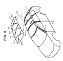
- Fig. 3 shows a vehicle body having a roof structure for a vehicle according to another embodiment of the present invention.
- respective reinforcement members 21a, 21b, 21c, 21d, 21e, 21f formed in a similar curved shape are disposed at positions similar to those shown in Fig. 1 , and in this embodiment, these reinforcement members are disposed integrally with the roof panel 4 in advance.
- the respective reinforcement members 21a, 21b, 21c, 21d, 21e, 21f are formed so as to be curved along the inner surface of roof panel 4 as compared with the respective reinforcement members shown in Fig.
- the roof structure for a vehicle according to the present invention can be applied to various vehicles having a roof.
Landscapes
- Engineering & Computer Science (AREA)
- Chemical & Material Sciences (AREA)
- Combustion & Propulsion (AREA)
- Transportation (AREA)
- Mechanical Engineering (AREA)
- Body Structure For Vehicles (AREA)
Abstract
Description
- The present invention relates to a roof structure for a vehicle having a beam structure, and specifically, to a roof structure for a vehicle realizing a lightweight, high-strength and high-rigidity structure by addition of reinforcement members.
- A roof for a vehicle is frequently formed by a joint structure of a beam structure and a panel member, and a structure is proposed wherein at the time of being input to the vehicle with a load due to a front surface collision or a side surface collision, a deformation of the roof is suppressed or an impact is absorbed, for example, by beam sections extending in the widthwise direction of the vehicle (for example, Patent document 1). However, in order to suppress the shear deformation (shear in plane or torsion) of the entire roof structure, it is required to take countermeasures such as increase of the number of beams or partial reinforcement of a beam joint corner, but if done so, there is a fear causing a problem such as reduction of vehicle handling stability accompanying with increase of the weight in addition to increase of the number of parts at the upper portion of the vehicle and increase of the assembly steps.
- On the other hand, as a material capable of enhancing mechanical properties (strength and rigidity) while securing a lightweight property, an FRP (Fiber Reinforced Plastic), in particular, a CFRP (Carbon Fiber Reinforced Plastic), is known. Therefore, although it is considered to efficiently enhance the strength and rigidity of a vehicle roof structure, for example, against input of a front surface collision load or a side surface collision load without accompanying significant increase of weight by using reinforcement members composed of such a lightweight material, there have been no proposals realizing such an improved structure in consideration of up to suppression of shear deformation of the entire roof structure (shear in plane or torsion).
- Patent document 1:
JP-A-2006-298021 - Accordingly, an object of the present invention is to provide a roof structure for a vehicle which can efficiently realize desirable mechanical properties such as strength and rigidity in a direction required for the roof structure without impairing the lightweight property of the entire roof structure by adding specified reinforcement members.
- To achieve the above-described object, a roof structure for a vehicle according to the present invention has one or more beam sections extending in a widthwise direction of the vehicle, and is characterized in that reinforcement members which extend obliquely relative to the widthwise direction of the vehicle either connect the beam sections together, or connect the beam sections and a vehicle body frame section together, the vehicle body frame section being located in front of or in rear of the beam sections, and the reinforcement members are configured from members each exhibiting a strength against pulling of a member in an extension direction of the member.
- In such a roof structure for a vehicle according to the present invention, since the reinforcement members extending obliquely relative to the widthwise direction of the vehicle are connected to one or more beam sections extending in a widthwise direction of the vehicle and these reinforcement members are configured from members each exhibiting a strength against pulling of a member in an extension direction of the member, it becomes possible to receive the compression load applied to the beam section with the tensile force of the reinforcement member, and it becomes possible to transmit it to, for example, the vehicle body frame section. Therefore, as compared with a case provided with only beam sections, merely by adding the specified reinforcement members, the strength and rigidity of the roof structure can be efficiently enhanced without significantly increasing the weight of the roof structure, and in addition, since these reinforcement members extend obliquely relative to the widthwise direction of the vehicle, they can exhibit forces for suppressing the shear deformation of the entire roof structure (shear in plane or torsion), and therefore, it becomes possible that the roof structure exhibits forces for suppressing deformation against external loads input from substantially all directions. In other words, in the roof structure according to the present invention, the strength and rigidity can be efficiently increased relative to substantially any direction without significantly increasing the weight.
- In the above-described roof structure for a vehicle according to the present invention, it is preferred that each of the above-described reinforcement members comprises a member having reinforcing fibers. As the material of the member having reinforcing fibers, in addition to a fiber reinforced resin, a fiber reinforced metal, etc. can be used. By being reinforced by reinforcing fibers, it becomes possible to enhance the strength and rigidity of the reinforcement member itself while securing lightweight property with material or shape, and it becomes possible to efficiently increase the strength and rigidity of the roof structure without significantly increasing the weight.
- Further, in case where the reinforcement member comprises a member having reinforcing fibers, it is preferred that at least a part of the reinforcing fibers are oriented in an extension direction of the reinforcement member. Since the reinforcement member is configured as a member exhibiting a strength relative to the pulling in the extension direction of the member, if the reinforcing fibers are oriented in the extension direction, it becomes possible to exhibit a high tensile strength.
- Further, the above-described reinforcement members can be provided at a formation being extended linearly in a direction toward the vehicle body frame section or the beam section, and in case where a roof panel is provided at an upper portion of the above-described roof structure, the reinforcement members can be provided also at a formation being extended in a direction along a lower surface of the roof panel, for example, at a curved shape. In case of the former formation, only the roof structure including the beam sections and the reinforcement members can be adequately reinforced substantially independently from the roof panel, and in case of the latter formation, it becomes possible to give a function for supporting the roof panel or a function for reinforcing the roof panel itself to the reinforcement members. Further, in case of the latter formation, it is also possible to provide the reinforcement members integrally with the roof panel and connect the reinforcement members of the roof panel to the vehicle body frame section or the beam sections. The selection of these formations can be carried out in accordance with a formation of the structure to be reinforced, a space required to the vehicle interior (namely, how much installation space can be allowed for the roof structure), etc.
- Furthermore, in case where the above-described reinforcement members comprise members having reinforcing fibers, as the kind of the reinforcing fibers, although arbitrary reinforcing fibers such as carbon fibers, glass fibers and aramide fibers or a combination of these fibers can be used, in particular, in case where it is required to enhance strength, rigidity and the like, it is preferred that carbon fibers are included as the reinforcing fibers.
- Thus, in the roof structure for a vehicle according to the present invention, while ensuring the light weight property without greatly increasing the weight of the upper portion of the vehicle which affects the vehicle handling stability, the strength and rigidity of the entire roof structure can be enhanced substantially in all directions, and it becomes possible to improve the safety performance against collision.
-
- [
Fig. 1] Fig. 1 is a partially exploded perspective view of a vehicle body having a roof structure for a vehicle according to an embodiment of the present invention. - [
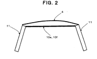
Fig. 2] Fig. 2 is a partial sectional view of the vehicle body depicted inFig. 1 as viewed along line A-A ofFig. 1 . - [
Fig. 3] Fig. 3 is a partially exploded perspective view of a vehicle body having a roof structure for a vehicle according to another embodiment of the present invention. - [
Fig. 4] Fig. 4 is a partial sectional view of the vehicle body depicted inFig. 3 as viewed along line B-B ofFig. 3 . - Hereinafter, embodiments of the present invention will be explained referring to figures.
-
Fig. 1 shows a vehicle body having a roof structure for a vehicle according to an embodiment of the present invention. Aroof 2 is provided at the upper portion of avehicle body 1, and in this embodiment, theroof 2 is formed from a roof structure 3 and aroof panel 4. Roof structure 3 has a plurality of (in this embodiment, two)beam sections beam sections front frame 7 connected to afront pillar 6, and arear frame 9 connected to apillar 8 at a rearmost position which is a so-called D pillar) and thebeam sections reinforcement members reinforcement members beam sections reinforcement members 10e, 10f extending obliquely relative to the widthwise direction of the vehicle.Reinforcement members reinforcement members reinforcement members 10e, 10f are disposed, respectively, so as to be crossed to each other.Beam section 5a is connected to acenter pillar 11, andbeam section 5b is connected to arear pillar 12. - Each of the above-described
reinforcement members reinforcement members Fig. 2 with the front side connecting portion ofreinforcement members 10e, 10f, thereinforcement members 10e, 10f extended linearly at a condition distanced fromroof panel 4 formed in a curved shape are connected tocenter pillar 11 as the vehicle body frame section, orbeam section 5a, or both of these. - In the roof structure for a vehicle 3 thus constructed, since a plurality of
reinforcement members beam sections beam sections - Further, since the
respective reinforcement members -
Fig. 3 shows a vehicle body having a roof structure for a vehicle according to another embodiment of the present invention. In this embodiment, along the curved inner surface ofroof panel 4 at the ceiling side of the vehicle interior,respective reinforcement members Fig. 1 , and in this embodiment, these reinforcement members are disposed integrally with theroof panel 4 in advance. In such a roof structure for avehicle 22 thus constructed, since therespective reinforcement members roof panel 4 as compared with the respective reinforcement members shown inFig. 1 which extend linearly (for example, as shown inFig. 4 with respect to the portion disposed withreinforcement members roof panel 4 in advance, it also becomes possible to facilitate the assembly of the entire roof. Because the other structures, operations and effects are similar to those in the embodiment shown inFig. 1 , the explanation will be omitted by providing the same symbols as those given inFig. 1 . - The roof structure for a vehicle according to the present invention can be applied to various vehicles having a roof.
-
- 1: vehicle body
- 2: roof
- 3, 22: roof structure
- 4: roof panel
- 5a, 5b: beam secton
- 6: front pillar
- 7: front frame
- 8: pillar at rearmost position
- 9: rear frame
- 10a, 10b, 10c, 10d, 10e, 10f, 21a, 21b, 21c, 21d, 21e, 21f: reinforcement member
- 11: center pillar
- 12: rear pillar
Claims (7)
- A roof structure for a vehicle having one or more beam sections extending in a widthwise direction of the vehicle, characterized in that reinforcement members which extend obliquely relative to the widthwise direction of the vehicle either connect said beam sections together, or connect said beam sections and a vehicle body frame section together, said vehicle body frame section being located in front of or in rear of said beam sections, and said reinforcement members are configured from members each exhibiting a strength against pulling of a member in an extension direction of the member.
- The roof structure for a vehicle according to claim 1, wherein each of said reinforcement members comprises a member having reinforcing fibers.
- The roof structure for a vehicle according to claim 1 or 2, wherein each of said reinforcement members comprises a member having reinforcing fibers and at least a part of said reinforcing fibers are oriented in an extension direction of the reinforcement member.
- The roof structure for a vehicle according to any of claims 1 to 3, wherein each of said reinforcement members comprises a fiber reinforced resin member.
- The roof structure for a vehicle according to any of claims 1 to 4, wherein each of said reinforcement members is extended linearly in a direction toward said vehicle body frame section or said beam section.
- The roof structure for a vehicle according to any of claims 1 to 4, wherein a roof panel is provided at an upper portion of said roof structure, and said reinforcement members are extended in a direction along a lower surface of said roof panel.
- The roof structure for a vehicle according to any of claims 2 to 6, wherein said reinforcing fibers of said reinforcement members include carbon fibers.
Applications Claiming Priority (2)
| Application Number | Priority Date | Filing Date | Title |
|---|---|---|---|
| JP2012186303 | 2012-08-27 | ||
| PCT/JP2013/072672 WO2014034586A1 (en) | 2012-08-27 | 2013-08-26 | Roof structure for vehicle |
Publications (2)
| Publication Number | Publication Date |
|---|---|
| EP2889204A1 true EP2889204A1 (en) | 2015-07-01 |
| EP2889204A4 EP2889204A4 (en) | 2016-04-13 |
Family
ID=50183398
Family Applications (1)
| Application Number | Title | Priority Date | Filing Date |
|---|---|---|---|
| EP13833873.6A Withdrawn EP2889204A4 (en) | 2012-08-27 | 2013-08-26 | Roof structure for vehicle |
Country Status (3)
| Country | Link |
|---|---|
| EP (1) | EP2889204A4 (en) |
| JP (1) | JPWO2014034586A1 (en) |
| WO (1) | WO2014034586A1 (en) |
Cited By (3)
| Publication number | Priority date | Publication date | Assignee | Title |
|---|---|---|---|---|
| CN107804374A (en) * | 2016-09-09 | 2018-03-16 | 铃木株式会社 | Vehicle body upper portion structure |
| CN107804373A (en) * | 2016-09-09 | 2018-03-16 | 铃木株式会社 | Vehicle body upper portion structure |
| US11945205B2 (en) | 2019-10-01 | 2024-04-02 | Nippon Steel Corporation | Curved panel part |
Families Citing this family (12)
| Publication number | Priority date | Publication date | Assignee | Title |
|---|---|---|---|---|
| JP6187772B2 (en) * | 2014-09-30 | 2017-08-30 | マツダ株式会社 | Body reinforcement structure |
| JP6229675B2 (en) * | 2015-02-18 | 2017-11-15 | マツダ株式会社 | Upper body structure of the vehicle |
| JP6237670B2 (en) * | 2015-02-18 | 2017-11-29 | マツダ株式会社 | Upper body structure of the vehicle |
| US9855972B2 (en) | 2015-04-16 | 2018-01-02 | Ford Global Technologies, Llc | Vehicle roof with truss structure |
| CN104875790A (en) * | 2015-05-26 | 2015-09-02 | 北京汽车股份有限公司 | Car roof cover and machining method for car roof cover |
| KR101794844B1 (en) * | 2016-01-05 | 2017-11-08 | 현대자동차주식회사 | Carbon Fiber Reinforced Plastic Roof-Panel |
| KR101786330B1 (en) * | 2016-04-18 | 2017-10-18 | 현대자동차주식회사 | Roof for vehicle |
| JP6319672B2 (en) * | 2016-07-21 | 2018-05-09 | マツダ株式会社 | Body reinforcement structure |
| JP6319671B2 (en) * | 2016-07-21 | 2018-05-09 | マツダ株式会社 | Body reinforcement structure |
| KR102261287B1 (en) * | 2017-02-28 | 2021-06-04 | 현대자동차 주식회사 | Vehicle roof |
| JP6677219B2 (en) * | 2017-05-29 | 2020-04-08 | Jfeスチール株式会社 | Body roof reinforcement structure |
| JP7322522B2 (en) * | 2019-06-05 | 2023-08-08 | マツダ株式会社 | upper body structure |
Family Cites Families (10)
| Publication number | Priority date | Publication date | Assignee | Title |
|---|---|---|---|---|
| US1289265A (en) * | 1918-12-31 | Richard Auto Mfg Company | Auto-top. | |
| DE3420781A1 (en) * | 1984-06-04 | 1985-01-31 | Stübbe GmbH, 2940 Wilhemshaven | ROOF FOR MOTOR VEHICLES |
| JPS61182377U (en) * | 1985-05-07 | 1986-11-13 | ||
| JPH07187007A (en) * | 1993-12-28 | 1995-07-25 | Mazda Motor Corp | Vehicle upper body structure |
| JP2001180533A (en) * | 1999-12-27 | 2001-07-03 | Mazda Motor Corp | Vehicle body structure |
| DE10359514B4 (en) * | 2003-12-18 | 2006-07-06 | Daimlerchrysler Ag | Roof attachment for a cab of a commercial vehicle |
| DE102005006201A1 (en) * | 2005-02-11 | 2006-08-31 | Audi Ag | Roof arrangement for motor vehicles |
| JP4547707B2 (en) | 2005-04-15 | 2010-09-22 | 関東自動車工業株式会社 | Automobile roof reinforcement structure |
| JP2009166408A (en) * | 2008-01-18 | 2009-07-30 | Toray Ind Inc | Structural member |
| DE102009040934B4 (en) * | 2009-09-11 | 2020-06-04 | GM Global Technology Operations LLC (n. d. Ges. d. Staates Delaware) | Plastic molding for a motor vehicle |
-
2013
- 2013-08-26 JP JP2013539047A patent/JPWO2014034586A1/en active Pending
- 2013-08-26 EP EP13833873.6A patent/EP2889204A4/en not_active Withdrawn
- 2013-08-26 WO PCT/JP2013/072672 patent/WO2014034586A1/en not_active Ceased
Cited By (3)
| Publication number | Priority date | Publication date | Assignee | Title |
|---|---|---|---|---|
| CN107804374A (en) * | 2016-09-09 | 2018-03-16 | 铃木株式会社 | Vehicle body upper portion structure |
| CN107804373A (en) * | 2016-09-09 | 2018-03-16 | 铃木株式会社 | Vehicle body upper portion structure |
| US11945205B2 (en) | 2019-10-01 | 2024-04-02 | Nippon Steel Corporation | Curved panel part |
Also Published As
| Publication number | Publication date |
|---|---|
| EP2889204A4 (en) | 2016-04-13 |
| JPWO2014034586A1 (en) | 2016-08-08 |
| WO2014034586A1 (en) | 2014-03-06 |
Similar Documents
| Publication | Publication Date | Title |
|---|---|---|
| EP2889204A1 (en) | Roof structure for vehicle | |
| US8857899B2 (en) | Vehicle | |
| US8419113B2 (en) | Structural member for vehicle | |
| US10077080B2 (en) | Vehicle | |
| US8991909B2 (en) | Vehicle | |
| JP5120409B2 (en) | Center pillar for vehicle | |
| JP6411149B2 (en) | Vehicle upper body frame system | |
| US20160059892A1 (en) | Rear structure of front side member | |
| EP2623399A1 (en) | Vehicle body structure | |
| WO2009003870A4 (en) | Structural component with rib and cross member element | |
| EP2684780A1 (en) | Rear structure of car body | |
| CN106995011A (en) | Vehicle body front structure | |
| US9914482B2 (en) | Vehicle side structure | |
| JP2008279904A (en) | Cross-sectional structure of structural members | |
| US20140103685A1 (en) | Lightweight Cross-Car Beam and Method of Construction | |
| CN109496183A (en) | The exterior plate of automobile | |
| CN113492921B (en) | vehicle | |
| US20110254320A1 (en) | Vehicle body side structure | |
| US20150001881A1 (en) | Vehicle body side structure | |
| JP5802598B2 (en) | vehicle | |
| JP2018030542A (en) | Vehicle components | |
| JPWO2013145232A1 (en) | Lower body structure | |
| JP6187772B2 (en) | Body reinforcement structure | |
| JP2007069667A (en) | Connecting structure of body frame members | |
| JP2015123886A (en) | Bumper reinforcement and vehicle body front structure |
Legal Events
| Date | Code | Title | Description |
|---|---|---|---|
| PUAI | Public reference made under article 153(3) epc to a published international application that has entered the european phase |
Free format text: ORIGINAL CODE: 0009012 |
|
| 17P | Request for examination filed |
Effective date: 20150318 |
|
| AK | Designated contracting states |
Kind code of ref document: A1 Designated state(s): AL AT BE BG CH CY CZ DE DK EE ES FI FR GB GR HR HU IE IS IT LI LT LU LV MC MK MT NL NO PL PT RO RS SE SI SK SM TR |
|
| AX | Request for extension of the european patent |
Extension state: BA ME |
|
| DAX | Request for extension of the european patent (deleted) | ||
| RA4 | Supplementary search report drawn up and despatched (corrected) |
Effective date: 20160316 |
|
| RIC1 | Information provided on ipc code assigned before grant |
Ipc: B62D 25/06 20060101AFI20160310BHEP |
|
| STAA | Information on the status of an ep patent application or granted ep patent |
Free format text: STATUS: THE APPLICATION HAS BEEN WITHDRAWN |
|
| 18W | Application withdrawn |
Effective date: 20161012 |