EP2889203A1 - Telescopic steering device - Google Patents
Telescopic steering device Download PDFInfo
- Publication number
- EP2889203A1 EP2889203A1 EP13831811.8A EP13831811A EP2889203A1 EP 2889203 A1 EP2889203 A1 EP 2889203A1 EP 13831811 A EP13831811 A EP 13831811A EP 2889203 A1 EP2889203 A1 EP 2889203A1
- Authority
- EP
- European Patent Office
- Prior art keywords
- column
- outer column
- supporting portion
- peripheral surface
- pair
- Prior art date
- Legal status (The legal status is an assumption and is not a legal conclusion. Google has not performed a legal analysis and makes no representation as to the accuracy of the status listed.)
- Granted
Links
Images






Classifications
-
- B—PERFORMING OPERATIONS; TRANSPORTING
- B62—LAND VEHICLES FOR TRAVELLING OTHERWISE THAN ON RAILS
- B62D—MOTOR VEHICLES; TRAILERS
- B62D1/00—Steering controls, i.e. means for initiating a change of direction of the vehicle
- B62D1/02—Steering controls, i.e. means for initiating a change of direction of the vehicle vehicle-mounted
- B62D1/16—Steering columns
- B62D1/18—Steering columns yieldable or adjustable, e.g. tiltable
- B62D1/19—Steering columns yieldable or adjustable, e.g. tiltable incorporating energy-absorbing arrangements, e.g. by being yieldable or collapsible
- B62D1/192—Yieldable or collapsible columns
-
- B—PERFORMING OPERATIONS; TRANSPORTING
- B21—MECHANICAL METAL-WORKING WITHOUT ESSENTIALLY REMOVING MATERIAL; PUNCHING METAL
- B21D—WORKING OR PROCESSING OF SHEET METAL OR METAL TUBES, RODS OR PROFILES WITHOUT ESSENTIALLY REMOVING MATERIAL; PUNCHING METAL
- B21D26/00—Shaping without cutting otherwise than using rigid devices or tools or yieldable or resilient pads, i.e. applying fluid pressure or magnetic forces
- B21D26/02—Shaping without cutting otherwise than using rigid devices or tools or yieldable or resilient pads, i.e. applying fluid pressure or magnetic forces by applying fluid pressure
- B21D26/033—Deforming tubular bodies
-
- B—PERFORMING OPERATIONS; TRANSPORTING
- B62—LAND VEHICLES FOR TRAVELLING OTHERWISE THAN ON RAILS
- B62D—MOTOR VEHICLES; TRAILERS
- B62D1/00—Steering controls, i.e. means for initiating a change of direction of the vehicle
- B62D1/02—Steering controls, i.e. means for initiating a change of direction of the vehicle vehicle-mounted
- B62D1/16—Steering columns
-
- B—PERFORMING OPERATIONS; TRANSPORTING
- B62—LAND VEHICLES FOR TRAVELLING OTHERWISE THAN ON RAILS
- B62D—MOTOR VEHICLES; TRAILERS
- B62D1/00—Steering controls, i.e. means for initiating a change of direction of the vehicle
- B62D1/02—Steering controls, i.e. means for initiating a change of direction of the vehicle vehicle-mounted
- B62D1/16—Steering columns
- B62D1/18—Steering columns yieldable or adjustable, e.g. tiltable
- B62D1/184—Mechanisms for locking columns at selected positions
-
- B—PERFORMING OPERATIONS; TRANSPORTING
- B62—LAND VEHICLES FOR TRAVELLING OTHERWISE THAN ON RAILS
- B62D—MOTOR VEHICLES; TRAILERS
- B62D1/00—Steering controls, i.e. means for initiating a change of direction of the vehicle
- B62D1/02—Steering controls, i.e. means for initiating a change of direction of the vehicle vehicle-mounted
- B62D1/16—Steering columns
- B62D1/18—Steering columns yieldable or adjustable, e.g. tiltable
- B62D1/185—Steering columns yieldable or adjustable, e.g. tiltable adjustable by axial displacement, e.g. telescopically
-
- B—PERFORMING OPERATIONS; TRANSPORTING
- B21—MECHANICAL METAL-WORKING WITHOUT ESSENTIALLY REMOVING MATERIAL; PUNCHING METAL
- B21D—WORKING OR PROCESSING OF SHEET METAL OR METAL TUBES, RODS OR PROFILES WITHOUT ESSENTIALLY REMOVING MATERIAL; PUNCHING METAL
- B21D53/00—Making other particular articles
- B21D53/88—Making other particular articles other parts for vehicles, e.g. cowlings, mudguards
Definitions
- the invention relates to a telescopic steering apparatus configured to adjust a front-rear position of a steering wheel.
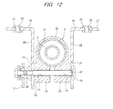
- Figs. 11 and 12 illustrate a tilt-telescopic steering apparatus disclosed in Patent Document 1.
- the steering apparatus has a steering shaft 2 having a rear end portion to which a steering wheel 1 is fixed, a steering column 3 rotatably supporting the steering shaft 2 therein, a steering force assist device 5 which applies assist torque to the steering shaft 2 using an electric motor 4 as an auxiliary power source, and a steering gear unit 7 which pushes or pulls tie-rods 6, 6 in accordance with a rotation of the steering shaft 2.
- a front-rear direction means a front-rear direction of a vehicle.
- the steering shaft 2 has an inner shaft 8 and an outer shaft 9.
- the inner shaft 8 and the outer shaft 9 are combined to transmit a rotational force and to be relatively displaced in an axial direction.
- a front end portion of the inner shaft 8 is connected to an input shaft of the steering force assist device 5 in a gear housing 10 of the steering force assist device 5.
- the steering column 3 has an inner column 11 and an outer column 12.
- a front end portion of the outer column 12 is fitted to a rear end portion outer side of the inner column 11 so that it can be relatively displaced in the axial direction.
- the inner column 11 is supported to a vehicle body 14 by a front fixed bracket 13 via the gear housing 10.
- the fixed bracket 13 swingably supports the gear housing 10 and the steering column 3 about a pivot pin 15.
- the front end portion of the outer column 12 is supported to the vehicle body 14 by a rear fixed bracket 17.
- the fixed bracket 17 is supported to the vehicle body 14 so that it is forwards separated when a strong forward shock is applied.
- the fixed bracket 17 has left and right side wall portions 18, 18 and support plate parts 19, 19 that are provided at upper end portions of the side wall portions 18, 18.
- Notches 20, 20 are provided for the support plate parts 19, 19 such that they are opened towards rear end edges of the support plate parts 19, 19.
- the notches 20, 20 are engaged with capsules 21, 21.
- the capsules 21, 21 are fixed to the vehicle body 14 by bolts (not shown).
- a high forward shock load is applied from a driver body to the steering column 3 via the steering wheel 1 and the steering shaft 2.
- the steering shaft 2 and the steering column 3 absorb this shock energy, and at the same time cause reduction in the entire length.
- the fixed bracket 17 is forwards displaced together with the outer column 12 and is thus forwards separated relative to the vehicle body 14, thereby permitting the steering wheel 1 to be forwards displaced.
- the outer column 12 is supported to the fixed bracket 17 so that it can be moved in front-rear and upper-lower directions.
- a pair of clamped portions 23, 23 forming a movable bracket 22 is integrated with the outer column 12 on a lower surface of the front end portion of the outer column 12.
- Column side through-holes 24, 24 elongated in the front-rear direction are formed through the clamped portions 23, 23, respectively, at locations aligned with each other.
- Vehicle body side through-holes 25, 25 elongated in the upper-lower direction are formed through a portion of the side wall portions 18, 18 at locations aligned with each other.
- a rod member 26 is inserted into the column side through-holes 24, 24 and the vehicle-side through-holes 25, 25 from one side to the other side (from the right to the left in Fig. 12 ).
- An adjusting nut 28 is screwed to an end of the other side of the rod member 26 so that the clamped portions 23, 23 are held by the side wall portions 18, 18, and is configured so that it can be rotated by an adjusting lever 27.
- a front end portion of an output shaft 16 of the steering force assist device 5 is coupled to a rear end portion of an intermediate shaft 31 via a universal joint 30.
- a front end portion of the intermediate shaft 31 is coupled to an input shaft 33 of the steering gear unit 7 via a separate universal joint 32.
- the tie-rods 6, 6 are pushed or pulled in connection with rotation of the input shaft 33, so that a desire steering angle is applied to the steering wheel.
- an outer column main body is first molded by a die-casting using a lightweight alloy such as aluminum alloy. Then, an inner peripheral surface of the outer column main body is subject to cutting work and is thus finished. For the steering apparatus, the cutting work for finishing an inner diameter of the outer column 12 with accuracy is troublesome and the processing cost is thus increased. Also, the inner peripheral surface of the outer column 12 and an outer peripheral surface of the inner column 11 are fitted over an entire circumference. Thus, when the inner diameter precision of the outer column 12 is not sufficient, a partial contact is caused, so that the inner column 11 cannot be stably maintained.
- Patent Document 2 discloses a telescopic steering apparatus in which protuberances 34, 34 protruding radially inward from an inner peripheral surface of an outer column are formed at a plurality of positions along a circumferential direction on the inner peripheral surface of the outer column 12a, and distal ends (radially inner end portions) of the respective protuberances 34, 34 contact an outer peripheral surface of an inner column 11a in an assembled state.
- an outer column main body is first molded by the die-casting.
- forging and broaching are performed on a portion of an inner peripheral surface of the outer column main body overlapping the outer peripheral surface of the inner column 11 a at a plurality of locations (eleven locations in the illustrated example) along a circumferential direction, thereby forming the respective protuberances 34, 34.
- the cutting work (the broaching and the like) is preferably performed only for the distal ends of the respective protuberances 34, 34. Therefore, compared to a configuration where the cutting work is performed for the entire inner peripheral surface of the outer column, it is possible to reduce the processing cost.
- the method of forming the outer column 12a and the method of the protuberances 34, 34 are different from each other. Hence, it takes much time to perform the processing and the processing cost is thus increased.
- the contacting conditions of all the protuberances 34, 34 and the outer peripheral surface of the inner column 11a are preferably the same. However, when the multiple protuberances 34, 34 are provided, like the outer column 12a, the process for making the contacting conditions be the same is troublesome.
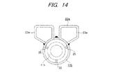
- Fig. 14 shows another outer column 12b disclosed in Patent Document 2.
- An inner peripheral surface of the outer column 12b is formed with support pawls 35, 35 at three circumferential positions facing an outer peripheral surface of an inner column 11b in an assembled state.
- the respective support pawls 35, 35 are formed by performing press processing for the outer column 12b and further bending processing from the inner peripheral surface of the outer column 12b radially inwards.
- the outer peripheral surface of the outer column 12b is provided with a movable bracket 22a at a part thereof in an axial direction.
- the movable bracket 22a has left and right clamped portions 23a, 23a.
- Each of the clamped portions 23a, 23a is formed by bending a plate-shaped material and has one end continuing from the outer peripheral surface of the outer column 12b and the other end welded to the outer peripheral surface of the outer column 12b.
- each of the support pawls 35, 35 has a cantilever-shaped structure where it is bent radially inwards from the inner peripheral surface of the outer column 12b. Hence, it is difficult to secure the stiffness for stably supporting the inner column 11b radially inside the outer column 12b. Also, the operation of welding the other end of the clamped portions 23a, 23a to the outer column 12b consumes much time, which increases the processing cost.
- Patent Documents 1, 3 and 4 disclose a structure where an energy absorption member for absorbing a shock load by plastic deformation is provided between a steering column (or a member fixed to the steering column) and a vehicle body (or a member fixed to the vehicle body) so as to alleviate shock, which is applied to a driver body upon a secondary collision, and to thus protect the driver, in addition to a structure of supporting the steering column to the vehicle body so that it can be forwards separated.
- Patent Document 5 discloses a technology of perforating a column during hydro forming process.
- An object of the invention is to provide a telescopic steering apparatus having a structure capable of stably maintaining an inner column radially inside an outer column and absorbing a shock load upon a collision at low cost.
- a telescopic steering apparatus includes a telescopic steering column, a steering shaft, a fixed bracket configured to be fixed to a vehicle body, a movable bracket, a rod member, and an adjusting lever.
- the steering column is configured such that an outer column and an inner column are telescopically combined.
- the outer column has a cylinder shape, an inner diameter of at least a portion of which in an axial direction is enlargeable and reducible, and has a supporting portion configured to support the inner column on an inner peripheral surface thereof.
- the inner column is arranged radially inside the outer column, and is fitted and supported by the supporting portion of the outer column in an axially displaceable manner.
- the steering shaft is rotatably supported radially inside the steering column and has a rear end portion protruding rearward from a rear end opening of the steering column and is configured such that a steering wheel is attached thereto.
- the fixed bracket has a pair of side wall portions provided at a fixed part so as to hold the portion of the outer column having the enlargeable and reducible inner diameter from both sides in a width direction, the pair of side wall portions being displaceable toward and away from each other in the width direction.
- the movable bracket has a pair of clamped portion that is formed integrally with the outer column by plastic forming, the pair of clamped portions being displaceable toward and away from each other in the width direction in accordance with a displacement of the pair of side wall portions toward and away from each other in the width direction.
- the rod member is arranged in the width direction such that the rod member is inserted into vehicle body side through-holes formed through the pair of side wall portions at locations aligned with each other and column side through-holes formed through the pair of clamped portions.
- the rod member widens or to narrows a gap between a pair of surfaces of the pair of side wall portions opposed to each other in accordance with a rotation of the adjusting lever.
- the adjusting lever is provided at a base end portion of the rod member to widen or to narrow the gap between the pair of surfaces by its rotation.
- An inner peripheral surface of the outer column has a shock absorbing portion at a location shifted toward one side in the axial direction from an axial end face of the inner column (on an advancing side of the inner column when the inner column and the outer column are relatively displaced in a compressing direction).
- a diameter of an inscribed circle of the shock absorbing portion is smaller than an outer diameter of the inner column.
- the outer column, including the supporting portion and the shock absorbing portion is formed by expanding a hollow pipe radially outwards.
- the movable bracket is formed integrally with the outer column by an expansion forming.
- the expansion forming is, for example, a hydroforming.
- the other examples of the expansion forming include a press working, a bulge forming, a vacuum forming, an air-blow forming and an explosive forming.
- the supporting portion of the outer column and the outer peripheral surface of the inner column may contact each other at three or more locations along a circumferential direction.
- the supporting portion of the outer column and the outer peripheral surface of the inner column may contact each other at only three locations in the circumferential direction.
- the supporting portion of the outer column may be finished by a cutting or a pressing.
- the shock absorbing portion may have protuberances that protrude radially inwards from the inner peripheral surface of the outer column at a plurality of locations along the circumferential direction on the inner peripheral surface of the outer column.
- the supporting portion and the shock absorbing portion may be aligned in phase with respect to a circumferential direction.
- the supporting portion and the shock absorbing portion may be provided continuously in the axial direction.
- the shock absorbing portion may be provided at a location that is symmetric to the supporting portion with respect to a virtual plane including a central axis of an inscribed circle of the supporting portion and perpendicular to the pair of side wall portions of the fixed bracket.
- the telescopic steering apparatus having the structure capable of stably maintaining the inner column radially inside the outer column and absorbing a shock load upon a secondary collision at low cost.
- the reason why the structure capable of stably maintaining the inner column radially inside the outer column can be implemented at low cost is because the outer column, including the supporting portion for supporting the inner column, and the movable bracket are integrally formed by an expansion forming such as a hydroforming for example. That is, even when the supporting portion has multiple (e.g., three or more) protuberances, it is possible to reduce the processing cost and to obtain the supporting portion having the high stiffness.
- the inner peripheral surface of the outer column is provided with the shock absorbing portion, the diameter of the inscribed circle of which is smaller than the outer diameter of the inner column, at the location shifted toward one side in the axial direction from the axial end face of the inner column, and the shock absorbing portion is formed by the expansion forming such as the hydroforming for example. That is, upon secondary collision, the inner column and the outer column are relatively displaced in a compressing direction such that the axial end face of the inner column frictionally moves along the shock absorbing portion of the outer column.
- the shock absorbing portion functions as a resistance against the compression of the inner column and the outer column and thus absorbs the shock energy applied to the steering wheel upon the secondary collision, thereby alleviating the shock applied to the driver body colliding with the steering wheel. Since the shock absorbing portion is directly formed at the outer column by the expansion forming, it is not necessary to provide a separate shock absorption member. As a result, it is possible to reduce the processing cost, the component management cost and the assembling cost.
- the supporting portion provided on the inner peripheral surface of the outer column and the outer peripheral surface of the inner column overlapping the supporting portion are configured to contact each other at only three locations along the circumferential direction, it is possible to enable the supporting portion to reliably contact the outer peripheral surface of the inner column. Also, since the number of the contacting locations is just three, it is possible to easily perform the process for making the contacting conditions the same for all the contacting locations.
- the supporting portion of the outer column When the supporting portion of the outer column is finished by cutting or pressing, it is possible to more stabilize the contacting condition of the supporting portion and the outer peripheral surface of the inner column.
- the supporting portion has multiple protuberances, it is possible to reduce the processing cost and to stably support the inner column by the supporting portion, compared to a configuration where the cutting work is performed for an entire circumference of an inner peripheral surface of an outer column having a simple cylindrical shape.
- the shock absorbing portion has the protuberances that protrude radially inwards from the inner peripheral surface of the outer column at a plurality of locations along a circumferential direction on the inner peripheral surface of the outer column, it is possible to prevent the inner column from being inclined relative to the outer column, based on the load of the complex directions applied to the inner column and the outer column upon the compression of the inner column and the outer column, and to secure the stable energy absorption performance. Furthermore, it is possible to adjust the energy absorption performance by adjusting the number of the protuberances.
- the supporting portion and the shock absorbing portion are aligned in phase with respect to the circumferential direction, it is possible to easily configure that the supporting portion and the shock absorbing portion are continuous in the axial direction.
- the supporting portion and the shock absorbing portion are made to be continuous in the axial direction, the inner column and the outer column can be smoothly (continuously) and stably compressed upon the secondary collision. As a result, it is possible to stably absorb the shock load upon secondary collision.
- the shock absorbing portion is provided at location that is symmetric to the supporting portion with respect to a virtual plane including the central axis of the inscribed circle of the supporting portion and perpendicular to the pair of side wall portions of the fixed bracket, it is possible to increase the contacting locations along the circumferential direction between the supporting portion and shock absorbing portion of the outer column and the outer peripheral surface of the inner column and to make the contacting locations be horizontally and vertically symmetric, when the inner column and the outer column are compressed and thus an axial end face of the inner column frictionally moves along the shock absorbing portion (in a state in which the shock load is absorbed). As a result, it is possible to more securely prevent the relative inclination of the inner column and the outer column, based on the load of the complex directions applied to the inner column and the outer column upon the secondary collision.
- Figs. 1 to 5 show a telescopic steering apparatus according to a first embodiment of the invention.
- the telescopic steering apparatus has a telescopic mechanism configured to adjust a front-rear position of a steering wheel 1 (see Fig. 11 ) and a tilt mechanism configured to adjust an upper-lower position of the steering wheel 1, like the structure shown in Figs. 11 and 12 .
- the invention is also applicable to a structure having no tilt mechanism.
- a method of operating the telescopic steering apparatus is similar to that of the telescopic steering apparatus of the related art shown in Figs. 11 and 12 .
- the illustrations and descriptions of parts similar to those of the related art are omitted or simplified.
- a steering column 3a of the telescopic steering apparatus of this embodiment has an outer column 12c configured as an upper column of the steering wheel 1-side (see Fig. 11 ) and an inner column 11c configured as a lower column of a side distant from the steering wheel 1.
- a front end portion of the outer column 12c has a cylindrical shape and has an elastically enlargeable and reducible inner diameter, and has a supporting portion 36 for fitting and supporting the inner column 11c radially inside the outer column 12c in an axially displaceable manner.
- the supporting portion 36 has a front supporting portion 37 and a rear supporting portion 38.
- the front supporting portion 37 and the rear supporting portion 38 are provided at locations at which they can contact an outer peripheral surface of the inner column 11c even when an axial range in which the outer column 12c and the inner column 11c radially overlap each other is the shortest (in a state where the entire length of the steering column 3a is maximally extended).
- the front supporting portion 37 has a plurality of protuberances 39, 39a formed on an inner peripheral surface of the outer column 12c.
- the respective protuberances 39, 39a are formed at three positions circumferentially equally spaced on the inner peripheral surface of the outer column 12c, along an axially overlapping range from the front end portion of the outer column 12c to a portion near front ends of column side through-holes 24a, 24a of a movable bracket 22c such that they protrude radially inwards from the inner peripheral surface of the outer column 12c.
- Distal ends (radially inner ends) of the respective protuberances 39, 39a are configured to contact the outer peripheral surface of the inner column 11c.
- the number of the protuberances 39, 39a is preferably three. However, after considering a balance such as processing cost and the like, the number of the protuberances 39, 39a may be larger than three (for example, a total of four, two by two at left and right sides).
- the positions at which the protuberances 39, 39a are formed are not limited to the positions circumferentially equally spaced on the inner peripheral surface of the outer column 12c. However, the protuberances 39, 39a are arranged to be distributed over a range exceeding a semicircle without having a partiality for the semicircle.
- the rear supporting portion 38 has a plurality of protuberances 39b, 39c that is formed on the inner peripheral surface of the outer column 12c.
- the respective protuberances 39b, 39c are formed at three positions circumferentially equally spaced on the inner peripheral surface of the outer column 12c, along an axially overlapping range from a portion near rear ends of the column side through-holes 24a, 24a of the movable bracket 22c to a location shifted slightly rearwards from the rear end portions of the column side through-holes 24a such that they protrude radially inwards from the inner peripheral surface of the outer column 12c.
- a portion between the front supporting portion 37 and the rear supporting portion 38 of the inner peripheral surface of the outer column 12c in the axial direction does not contact the outer peripheral surface of the inner column 11c.
- the supporting portions may be formed to be continuous (the front supporting portion and the rear supporting portion are continuously connected) in the axial direction.
- both sides in the width direction (the left-right direction in Fig. 3 ) of the outer peripheral surface of the outer column 12c are pressed to the inner side surfaces of the side wall portions 18a, 18a of the fixed bracket 17a. In this way, it is possible to position the steering column 3a and to secure the flexural stiffness in the width direction.
- the inner peripheral surface of the outer column 12c is provided with a shock absorbing portion 40 at a location shifted toward one side (rear side) in the axial direction from an axial end face of the inner column 11c (an end face on an advancing side seen from the inner column 11c when the inner column 11c and the outer column 12c are relatively displaced in a compression direction, in the present example, the rear end face).
- the shock absorbing portion 40 has protuberances 41, 41 that are formed to protrude radially inwards from the inner peripheral surface at positions circumferentially equally spaced on the inner peripheral surface of the outer column 12c.
- a diameter R 40 of an inscribed circle of the respective protuberances 41, 41 is smaller than an outer diameter of the inner column 11c.
- the respective protuberances 41, 41 of the shock absorbing portion 40 and the respective protuberances 39, 39a, 39b, 39c of the supporting portion 36 are aligned in phase with respect to a circumferential direction.
- the outer column 12c (including the supporting portion 36 and the shock absorbing portion 40) is formed by a hydroforming according to which a fluid pressure (e.g., a hydraulic pressure) is applied to an inner peripheral surface of a metal pipe, a hollow member made of a steel plate material or aluminum alloy material, to plastically deform the metal pipe radially outwards.
- a fluid pressure e.g., a hydraulic pressure
- a metal pipe is set in a mold having an inner surface shape conforming to an outer surface shape of the outer column 12c that is to be formed by expanding a diameter thereof. Then, both ends of the metal pipe are blocked by a shaft pressing tool and the like and a high fluid pressure is applied into the metal pipe.
- the metal pipe is expanded radially outwards until it firmly contacts an inner surface of a cavity of the mold, so that the outer column 12c is formed. Also, after the forming by the hydroforming, the finishing processing by the cutting work or press is performed for distal ends of the respective protuberances 39, 39a (39b, 39c) of the supporting portion 36 (the front and rear supporting portions 37, 38), as required.
- the method of forming the outer column 12c is not limited to the hydroforming, and a press working, a bulge forming, a vacuum forming, an air-blow forming, an explosive forming and the like are also possible.
- the movable bracket 22c is integrally formed with the outer column 12c by a hydroforming and has a pair of clamped portions 23b, 23b and a bottom part 42, the clamped portions 23b, 23b being held by the side wall portions 18a, 18a of the fixed bracket 17a and are displaceable toward and away from each other in the width direction,.
- the method for forming the movable bracket 22c is not limited to the hydroforming, and may be a press working, a bulge forming, a vacuum forming, an air-blow forming, an explosive forming and the like.
- the clamped portions 23b, 23b are formed in parallel with each other in a state in which respective one ends thereof are continuous to lower ends of the protuberances 39a, 39c formed at the lower of Fig. 3 of the respective protuberances 39, 39a, 39b, 39c of the supporting portion 36 (the front and rear supporting portions 37, 38) of the outer column 12c.
- the column side through-holes 24a, 24a elongated in the axial direction are formed through the clamped portions 23b, 23b respectively at locations aligned with each other.
- the column side through-holes 24a, 24a can be also formed by the hydroforming (see, e.g., Patent Document 5).
- the bottom part 42 continuously connects lower ends of the clamped portions 23b, 23b in the width direction (the left-right direction in Fig. 3 ).
- the method for integrally forming the movable bracket 22c and the outer column 12c is also not limited to the hydroforming, and may be a press working, a bulge forming, a vacuum forming, an air-blow forming, an explosive forming and the like.
- the telescopic steering apparatus of this embodiment it is possible to implement the structure capable of stably maintaining the inner column 11c radially inside the outer column 12c and absorbing a shock load upon a secondary collision at low cost.
- the reason to implement the structure capable of stably maintaining the inner column 11c radially inside the outer column 12c at low cost is because the outer column 12c including the supporting portion 36 (the front and rear supporting portions 37, 38) for supporting the inner column 11c and the movable bracket 22c are integrally formed by the hydroforming.
- the supporting portion 36 (the front and rear supporting portions 37, 38) is configured by the multiple (for example, three or more) respective protuberances 39, 39a, 39b, 39c, it is possible to reduce the processing cost and to obtain the supporting portion having the high stiffness.
- the inner peripheral surface of the outer column 12c is provided with the shock absorbing portion 40, the diameter of the inscribed circle of which is smaller than the outer diameter of the inner column 11c, at a location shifted toward one side in the axial direction from the axial end face of the inner column 11c, and the shock absorbing portion 40 is formed simultaneously with the respective protuberances 39, 39a, 39b, 39c by the expansion forming such as the hydroforming, for example.
- the inner column 11c and the outer column 12c are relatively displaced in the direction in which the steering column 3a is compressed (see Fig.
- the shock absorbing portion 40 functions as a resistance against the relative displacement of the inner column 11c and the outer column 12c and thus absorbs the shock energy applied to the steering wheel upon the secondary collision. Since the shock absorbing portion 40 is directly formed at the outer column 12c, it is not necessary to provide a separate shock absorption member. As a result, it is possible to reduce the processing cost, the component management cost and the assembling cost.
- the supporting portion 36 (the front and rear supporting portions 37, 38) provided on the inner peripheral surface of the outer column 12c and the outer peripheral surface of the inner column 11c overlapping the supporting portion 36 contact each other at three locations along the circumferential direction. Therefore, the respective protuberances 39, 39b reliably contact the outer peripheral surface of the inner column 11c without increasing the processing accuracy of the respective protuberances 39, 39b of the supporting portion 36.
- the finishing processing by cutting work or press is performed for the distal ends of the respective protuberances 39, 39a, 39b, 39c of the supporting portion 36. Even when the finishing processing is performed, since only the three protuberances 39, 39a, 39b, 39c are provided, it is sufficient to make the diameter of the inscribed circle of the protuberances 39, 39a, 39b, 39c at the three positions be the same in the axial direction. Therefore, the finishing processing by cutting work or press is not troublesome and the inner column 11c can be stably supported by the supporting portion 36 (the front and rear supporting portions 37, 38).
- the respective protuberances 39, 39a, 39b, 39c of the supporting portion 36 are formed to have the mountain-like shape by the hydroforming. Therefore, compared to the structure of the related art shown in Fig. 14 , it is possible to increase the stiffness for supporting the inner column 11c.
- the other structures and operations are the same as the steering apparatus of the related art as described above.
- Fig. 6 shows an outer column 12d of a telescopic steering apparatus according to a second embodiment of the invention.
- the respective protuberances 39, 39a, 39b, 39c of the supporting portion 36 (the front and rear supporting portions 37, 38) of the outer column 12d and the protuberances 41, 41 of the shock absorbing portion 40 are aligned in phase with respect to the circumferential direction.
- the axial rear ends of the respective protuberances 39b, 39c of the rear supporting portion 38 and the axial front ends of the protuberances 41, 41 of the shock absorbing portion 40 are smoothly continued by continuing parts 43, 43.
- the inner column 11c see Figs. 1 and 3
- the outer column 12d can be smoothly and stably compressed. As a result, it is possible to stably absorb the shock load upon the secondary collision.
- the other structures, operations and effects are similar to those of the first embodiment.
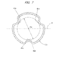
- Fig. 7 shows an outer column 12e of a telescopic steering apparatus according to a third embodiment of the invention.
- the respective protuberances 39, 39a, 39b, 39c of the supporting portion 36 (the front and rear supporting portions 37, 38) of the outer column 12e are provided in a similar manner as in the above embodiment (see Figs. 1 to 4 ).
- Respective protuberances 41a, 41a of a shock absorbing portion 40a are provided at locations (the upper and lower locations are opposite to the above embodiment) that are symmetric to the supporting portion 36 (the front and rear supporting portions 37, 38) with respect to a virtual plane ⁇ passing through a central axis O 36 of an inscribed circle X36 (see Fig. 4 ) of the supporting portion 36 and perpendicular to the side wall portions 18a, 18a of the fixed bracket 17a.
- the telescopic steering apparatus it is possible to increase the contacting locations along the circumferential direction (in the present example, six locations) between the respective protuberances 39, 39b of the supporting portion 36 (the front and rear supporting portions 37, 38) and respective protuberances 41 a, 41a of the shock absorbing portion 40a and the outer peripheral surface of the inner column 11c, when the inner column 11c (see Figs. 1 and 3 ) and the outer column 12e are compressed and thus the end face of the inner column 11c frictionally moves the respective protuberances 41 a, 41 a of the shock absorbing portion 40a (in a state in which the shock load is absorbed).
- Fig. 8 shows an outer column 12f of a telescopic steering apparatus according to a fourth embodiment of the invention.
- the respective protuberances 39, 39b of the supporting portion 36 (the front and rear supporting portions 37, 38) of the outer column 12f are provided in a similar manner as in the fourth embodiment (see Figs. 1 to 4 ).
- Respective protuberances 41b, 41b forming a shock absorbing portion 40b are provided at two positions circumferentially equally spaced on an inner peripheral surface of the outer column 12f (in the present example, at upper and lower ends in a state mouthed on the vehicle).
- the number (two along the circumferential direction) of the respective protuberances 41b, 41b of the shock absorbing portion 40b is smaller than the above embodiments (three along the circumferential direction). Therefore, it is possible to reduce a resistance force when the inner column 11c (see Figs. 1 and 3 ) and the outer column 12f are compressed and thus the end face of the inner column 11c frictionally moves along the respective protuberances 41 b, 41 b of the shock absorbing portion 40b.
- the other structures, operations and effects are similar to those of the above embodiments.
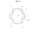
- Fig. 9 shows an outer column 12g of a telescopic steering apparatus according to a fifth embodiment of the invention.
- the respective protuberances 39, 39a (39b, 39c) of the supporting portion 36 (the front and rear supporting portions 37, 38) of the outer column 12g are provided in a similar manner as in the first to third embodiments (see Figs. 1 to 4 ).
- Respective protuberances 41c, 41c of a shock absorbing portion 40c are provided at four locations along the circumferential direction on an inner peripheral surface of the outer column 12g (at positions that are inclined by about 30° in the upper-lower direction relative to the virtual plane ⁇ passing through the central axis O 36 of the inscribed circle X36 (see Fig. 4 ) of the supporting portion 36 (the front and rear supporting portions 37, 38) and perpendicular to the side wall portions 18a, 18a of the fixed bracket 17a (see Figs. 3 and 4 ).
- the number (four along the circumferential direction) of the respective protuberances 41c, 41c of the shock absorbing portion 40c is larger than the above embodiments (three along the circumferential direction). Therefore, it is possible to increase a resistance force when the inner column 11c (see Figs. 1 and 3 ) and the outer column 12g are compressed and thus the end surface of the inner column 11c frictionally moves along the respective protuberances 41c, 41c of the shock absorbing portion 40c.
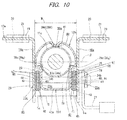
- Fig. 10 shows a telescopic steering apparatus according to a sixth embodiment of the invention.
- the telescopic steering apparatus of this embodiment is different from the telescopic steering apparatus of the first embodiment, in that first and second frictional plates 44,45, which will be described later, are provided and a structure of the movable bracket 22d is designed so as to provide the first and second frictional plates 44, 45. Therefore, the different structure is intensively described in the below.
- the structure of this embodiment can be implemented by a combination with the structures of the above embodiments.
- an outer column 12h forming the telescopic steering apparatus of this embodiment has a cylinder shape, an inner diameter of at least a portion in the axial direction is elastically enlargeable and reducible, and has a supporting portion 36a for fitting and supporting the inner column 11c radially inside the outer column 12h in an axially displaceable manner.
- the supporting portion 36a is configured by a front supporting portion 37a and a rear supporting portion 38a. The axial positions of the front supporting portion 37a and the rear supporting portion 38a are the same as the structure of the first embodiment.
- Protuberances 39e, 39g formed at the lower of Fig. 9 of respective protuberances 39d, 39e, 39f, 39g of the front and rear supporting portions 37a, 38a and the outer peripheral surface of the inner column 11c contact each other at locations that are inclined by an angle ⁇ (in the present example, 30°) towards the movable bracket 22d (towards the lower side in Fig. 10 ) with respect to a virtual plane ⁇ including a central axis O 11 of the inner column 11c and perpendicular to the side wall portions 18a, 18a of the fixed bracket 17a.
- angle ⁇ is made to be larger (a size in the width direction between the protuberances 39e, 39e (39g, 39g) formed at the lower in Fig.
- the movable bracket 22d has a pair of clamped portions 23c, 23c and a bottom part 42a connecting lower ends of the clamped portions 23c, 23c, the clamped portions 23c, 23c being provided to protrude downwards from the front end portion of the outer column 12h and held between the inner side surfaces of the side wall portions 18a, 18a as the gap between the inner side surfaces of the side wall portions 18a, 18a of the fixed bracket 17a is widened or narrowed.
- the clamped portions 23c, 23c are formed in parallel with each other in a state in which respective one ends thereof are continuous to the outer column 12h from lower ends of the protuberances 39e, 39e (39g, 39g) formed at the lower.
- Column side through-holes 24b, 24b elongated in the axial direction are formed through the clamped portions 23c, 23c respectively at location aligned with each other.
- a size W in the width direction between the inner side surfaces of the side wall portions 18a, 18a of the fixed bracket 17a in the width direction is substantially the same as a sum of a length D between outer side surfaces of the clamped portions 23c, 23c in the width direction (the left-right direction in Fig. 9 ) and a summed thickness 2T 45 of the first and second frictional plates 44, 45 (W ⁇ D + 2T 45 ).
- the first frictional plates 44, 44 and the second frictional plates 45, 45 are respectively arranged one by one between the inner side surfaces of the side wall portions 18a, 18a in the width direction and the outer side surfaces of the clamped portions 23c, 23c in the width direction.
- Each of the first frictional plates 44, 44 is a plate-shaped member made of a lightweight alloy material such as an iron-based alloy, an aluminum-based alloy, a magnesium-based alloy and the like and is elongated in the front-rear direction.
- the first frictional plates 44, 44 are respectively formed with first frictional plate side through-holes 46 into which the rod member 26 can be inserted and which are elongated in the front-rear direction, at locations at which at least the column side through-holes 24b, 24b of the clamped portions 23c, 23c are aligned.
- each of the first frictional plates 44, 44 are supported to the clamped portions 23c, 23c so that they can be only displaced in the width direction by a guide pin (not shown). That is, the respective first frictional plates 44, 44 are supported to the movable bracket 22d so that they can be moved in conjunction with the movable bracket 22d in the front-rear and upper-lower directions.
- Each of the second frictional plates 45, 45 has a pair of frictional plate parts 47, 47, which are arranged in parallel with each other, and a continuing part 48 that continues lower end portions of the frictional plate parts 47, 47, and has a U-shaped sectional shape.
- Each of the second frictional plates 45, 45 is formed by bending a plate-shaped member made of a lightweight alloy material such as an iron-based alloy, an aluminum-based alloy, a magnesium-based alloy and the like.
- a pair of second frictional plate side through-holes 49, 49 into which the rod member 26 can be inserted without play is formed. That is, in a state in which the rod member 26 is inserted into the second frictional plate side through-holes 49, 49, the respective second frictional plates 45, 45 can be moved in conjunction with the rod member 26 and the rod member 26 can be axially displaced.
- the respective first frictional plates 44, 44 and the respective second frictional plates 45, 45 are arranged between the side wall portions 18a, 18a and the clamped portions 23c, 23c with the one first frictional plate 44, 44 being held between the frictional plate parts 47, 47 of the respective second frictional plates 45, 45 in a state in which the continuing part 48 of the one second frictional plate 45,45 is faced downwards.
- the outer column 12h and the respective first and second frictional plates 44, 45 of the telescopic steering apparatus of this embodiment are mounted as shown in Fig. 10 .
- the adjusting lever 27 is rotated in a predetermined direction, like the structure of the related art as described above, thereby elastically widening the gap between the inner side surfaces of the side wall portions 18a, 18a.
- the surface pressures at the respective contacting locations between the side wall portions 18a, 18a, the first frictional plates 44, 44, the second frictional plates 45, 45 and the clamped portions 23c, 23c are lowered or lost.
- the gap between the inner side surfaces of the side wall portions 18a, 18a is narrowed and the surface pressures at the respective contacting locations between the side wall portions 18a, 18a, the first frictional plates 44, 44, the second frictional plates 45, 45 and the clamped portions 23c, 23c are increased.
- the surface pressure of the fitting part between the supporting portion 36a (the front supporting portion 37a and the rear supporting portion 38a) of the outer column 12h and the outer peripheral surface of the inner column 11c is increased.
- the steering wheel 1 is supported at an adjusted position.
- the first frictional plates 44, 44 and the second frictional plates 45, 45 are provided between the inner side surfaces of the side wall portions 18a, 18a and the clamped portions 23c, 23c. Therefore, it is possible to increase the frictional force by increasing a sum of the frictional areas of the respective contacting locations between the side wall portions 18a, 18a, the first frictional plates 44, 44, the second frictional plates 45, 45 and the clamped portions 23c, 23c. As a result, it is possible to stably support the steering wheel 1 at the adjusted position.
- the present embodiment can be combined with the above respective embodiments. The other structures, operations and effects are similar to those of the first embodiment.
- a steering apparatus including a telescopic mechanism configured to adjust a front-rear position of a steering wheel and a tilt mechanism configured to adjust an upper-lower position of the steering wheel.
- the present invention is also applicable to a steering apparatus having only the telescopic mechanism.
- the positional relation of the outer column and inner column of the steering column in the front-rear direction is irrelevant.
- the inner column may be provided on the rear side and the outer column may be provided on the front side.
Landscapes
- Engineering & Computer Science (AREA)
- Mechanical Engineering (AREA)
- Chemical & Material Sciences (AREA)
- Combustion & Propulsion (AREA)
- Transportation (AREA)
- Physics & Mathematics (AREA)
- Fluid Mechanics (AREA)
- Steering Controls (AREA)
- Shaping Metal By Deep-Drawing, Or The Like (AREA)
Abstract
Description
- The invention relates to a telescopic steering apparatus configured to adjust a front-rear position of a steering wheel.
-
Figs. 11 and12 illustrate a tilt-telescopic steering apparatus disclosed inPatent Document 1. The steering apparatus has asteering shaft 2 having a rear end portion to which asteering wheel 1 is fixed, a steering column 3 rotatably supporting thesteering shaft 2 therein, a steering force assist device 5 which applies assist torque to thesteering shaft 2 using anelectric motor 4 as an auxiliary power source, and asteering gear unit 7 which pushes or pulls tie-rods steering shaft 2. In this description, a front-rear direction means a front-rear direction of a vehicle. - The
steering shaft 2 has aninner shaft 8 and an outer shaft 9. Theinner shaft 8 and the outer shaft 9 are combined to transmit a rotational force and to be relatively displaced in an axial direction. A front end portion of theinner shaft 8 is connected to an input shaft of the steering force assist device 5 in agear housing 10 of the steering force assist device 5. The steering column 3 has aninner column 11 and anouter column 12. A front end portion of theouter column 12 is fitted to a rear end portion outer side of theinner column 11 so that it can be relatively displaced in the axial direction. Theinner column 11 is supported to avehicle body 14 by a front fixedbracket 13 via thegear housing 10. The fixedbracket 13 swingably supports thegear housing 10 and the steering column 3 about apivot pin 15. The front end portion of theouter column 12 is supported to thevehicle body 14 by a rearfixed bracket 17. - The
fixed bracket 17 is supported to thevehicle body 14 so that it is forwards separated when a strong forward shock is applied. As shown inFig. 12 , thefixed bracket 17 has left and rightside wall portions support plate parts side wall portions Notches support plate parts support plate parts notches capsules capsules vehicle body 14 by bolts (not shown). - Upon a collision accident, a high forward shock load is applied from a driver body to the steering column 3 via the
steering wheel 1 and thesteering shaft 2. Thesteering shaft 2 and the steering column 3 absorb this shock energy, and at the same time cause reduction in the entire length. As a result, thefixed bracket 17 is forwards displaced together with theouter column 12 and is thus forwards separated relative to thevehicle body 14, thereby permitting thesteering wheel 1 to be forwards displaced. - In order to adjust front-rear and upper-lower positions of the
steering wheel 1, theouter column 12 is supported to thefixed bracket 17 so that it can be moved in front-rear and upper-lower directions. A pair of clampedportions movable bracket 22 is integrated with theouter column 12 on a lower surface of the front end portion of theouter column 12. Column side through-holes portions holes side wall portions rod member 26 is inserted into the column side through-holes holes Fig. 12 ). An adjustingnut 28 is screwed to an end of the other side of therod member 26 so that the clampedportions side wall portions lever 27. - Therefore, by rotating the adjusting
nut 28 on the basis of an operation of the adjustinglever 27 to thus change an interval between the adjustingnut 28 and ahead part 29 of therod member 26, it is possible to fix theouter column 12 to thefixed bracket 17 or to release the outer column from thefixed bracket 17 and to fix theouter column 12 to theinner column 11 or to release the outer column from theinner column 11. In a state in which the interval between the adjustingnut 28 and thehead part 29 is widened, it is possible to move theouter column 12 forwards and rearwards (to displace the outer column relative to the inner column 11) within a range (a telescopic adjusting range) in which therod member 26 can be displaced in the respective column side through-holes steering wheel 1. Furthermore, it is possible to move the steering column 3 upwards and downwards within a range (a tilt adjusting range) in which therod member 26 can be displaced in the respective vehicle body side through-holes steering wheel 1. That is, at the state where the interval between the adjustingnut 28 and thehead part 29 is widened, it is possible to adjust the front-rear and upper-lower positions of thesteering wheel 1 within the ranges in which therod member 26 can be displaced in the respective column side through-holes holes - A front end portion of an
output shaft 16 of the steering force assist device 5 is coupled to a rear end portion of anintermediate shaft 31 via auniversal joint 30. A front end portion of theintermediate shaft 31 is coupled to aninput shaft 33 of thesteering gear unit 7 via a separateuniversal joint 32. The tie-rods input shaft 33, so that a desire steering angle is applied to the steering wheel. - When manufacturing the
outer column 12 as described above, an outer column main body is first molded by a die-casting using a lightweight alloy such as aluminum alloy. Then, an inner peripheral surface of the outer column main body is subject to cutting work and is thus finished. For the steering apparatus, the cutting work for finishing an inner diameter of theouter column 12 with accuracy is troublesome and the processing cost is thus increased. Also, the inner peripheral surface of theouter column 12 and an outer peripheral surface of theinner column 11 are fitted over an entire circumference. Thus, when the inner diameter precision of theouter column 12 is not sufficient, a partial contact is caused, so that theinner column 11 cannot be stably maintained. - Thus, as shown in
Fig. 13 ,Patent Document 2 discloses a telescopic steering apparatus in whichprotuberances outer column 12a, and distal ends (radially inner end portions) of therespective protuberances inner column 11a in an assembled state. When manufacturing theouter column 12a, an outer column main body is first molded by the die-casting. After that, forging and broaching are performed on a portion of an inner peripheral surface of the outer column main body overlapping the outer peripheral surface of theinner column 11 a at a plurality of locations (eleven locations in the illustrated example) along a circumferential direction, thereby forming therespective protuberances - In the case of the
outer column 12a as described above, the cutting work (the broaching and the like) is preferably performed only for the distal ends of therespective protuberances outer column 12a and the method of theprotuberances inner column 11a radially inside theouter column 12a without partial contact or play, the contacting conditions of all theprotuberances inner column 11a are preferably the same. However, when themultiple protuberances outer column 12a, the process for making the contacting conditions be the same is troublesome. -
Fig. 14 shows anotherouter column 12b disclosed inPatent Document 2. An inner peripheral surface of theouter column 12b is formed withsupport pawls inner column 11b in an assembled state. Therespective support pawls outer column 12b and further bending processing from the inner peripheral surface of theouter column 12b radially inwards. The outer peripheral surface of theouter column 12b is provided with amovable bracket 22a at a part thereof in an axial direction. Themovable bracket 22a has left and right clampedportions portions outer column 12b and the other end welded to the outer peripheral surface of theouter column 12b. - In the case of the
outer column 12b, thesupport pawls support pawls inner column 11b be the same. However, each of thesupport pawls outer column 12b. Hence, it is difficult to secure the stiffness for stably supporting theinner column 11b radially inside theouter column 12b. Also, the operation of welding the other end of the clampedportions outer column 12b consumes much time, which increases the processing cost. -
Patent Documents -
- Patent Document 1:
JP 2011-218941 A - Patent Document 2:
JP 2008-302751 A - Patent Document 3:
JP 2005-219641 A - Patent Document 4:
JP 2000-6821 A - Patent Document 5:
JP 2006-255785 A - An object of the invention is to provide a telescopic steering apparatus having a structure capable of stably maintaining an inner column radially inside an outer column and absorbing a shock load upon a collision at low cost.
- According to an aspect of the invention, a telescopic steering apparatus includes a telescopic steering column, a steering shaft, a fixed bracket configured to be fixed to a vehicle body, a movable bracket, a rod member, and an adjusting lever. The steering column is configured such that an outer column and an inner column are telescopically combined. The outer column has a cylinder shape, an inner diameter of at least a portion of which in an axial direction is enlargeable and reducible, and has a supporting portion configured to support the inner column on an inner peripheral surface thereof. The inner column is arranged radially inside the outer column, and is fitted and supported by the supporting portion of the outer column in an axially displaceable manner. The steering shaft is rotatably supported radially inside the steering column and has a rear end portion protruding rearward from a rear end opening of the steering column and is configured such that a steering wheel is attached thereto. The fixed bracket has a pair of side wall portions provided at a fixed part so as to hold the portion of the outer column having the enlargeable and reducible inner diameter from both sides in a width direction, the pair of side wall portions being displaceable toward and away from each other in the width direction. The movable bracket has a pair of clamped portion that is formed integrally with the outer column by plastic forming, the pair of clamped portions being displaceable toward and away from each other in the width direction in accordance with a displacement of the pair of side wall portions toward and away from each other in the width direction. The rod member is arranged in the width direction such that the rod member is inserted into vehicle body side through-holes formed through the pair of side wall portions at locations aligned with each other and column side through-holes formed through the pair of clamped portions. The rod member widens or to narrows a gap between a pair of surfaces of the pair of side wall portions opposed to each other in accordance with a rotation of the adjusting lever. The adjusting lever is provided at a base end portion of the rod member to widen or to narrow the gap between the pair of surfaces by its rotation.
- An inner peripheral surface of the outer column has a shock absorbing portion at a location shifted toward one side in the axial direction from an axial end face of the inner column (on an advancing side of the inner column when the inner column and the outer column are relatively displaced in a compressing direction). A diameter of an inscribed circle of the shock absorbing portion is smaller than an outer diameter of the inner column. The outer column, including the supporting portion and the shock absorbing portion, is formed by expanding a hollow pipe radially outwards. The movable bracket is formed integrally with the outer column by an expansion forming.
- The expansion forming is, for example, a hydroforming. The other examples of the expansion forming include a press working, a bulge forming, a vacuum forming, an air-blow forming and an explosive forming. The supporting portion of the outer column and the outer peripheral surface of the inner column may contact each other at three or more locations along a circumferential direction. For example, the supporting portion of the outer column and the outer peripheral surface of the inner column may contact each other at only three locations in the circumferential direction.
- The supporting portion of the outer column may be finished by a cutting or a pressing. The shock absorbing portion may have protuberances that protrude radially inwards from the inner peripheral surface of the outer column at a plurality of locations along the circumferential direction on the inner peripheral surface of the outer column.
- The supporting portion and the shock absorbing portion may be aligned in phase with respect to a circumferential direction. The supporting portion and the shock absorbing portion may be provided continuously in the axial direction. The shock absorbing portion may be provided at a location that is symmetric to the supporting portion with respect to a virtual plane including a central axis of an inscribed circle of the supporting portion and perpendicular to the pair of side wall portions of the fixed bracket.
- According to the one aspect of the invention, it is possible to provide the telescopic steering apparatus having the structure capable of stably maintaining the inner column radially inside the outer column and absorbing a shock load upon a secondary collision at low cost. First, the reason why the structure capable of stably maintaining the inner column radially inside the outer column can be implemented at low cost is because the outer column, including the supporting portion for supporting the inner column, and the movable bracket are integrally formed by an expansion forming such as a hydroforming for example. That is, even when the supporting portion has multiple (e.g., three or more) protuberances, it is possible to reduce the processing cost and to obtain the supporting portion having the high stiffness.
- The reason why the structure capable of absorbing the shock load upon secondary collision cam be implemented at low cost is because the inner peripheral surface of the outer column is provided with the shock absorbing portion, the diameter of the inscribed circle of which is smaller than the outer diameter of the inner column, at the location shifted toward one side in the axial direction from the axial end face of the inner column, and the shock absorbing portion is formed by the expansion forming such as the hydroforming for example. That is, upon secondary collision, the inner column and the outer column are relatively displaced in a compressing direction such that the axial end face of the inner column frictionally moves along the shock absorbing portion of the outer column. The shock absorbing portion functions as a resistance against the compression of the inner column and the outer column and thus absorbs the shock energy applied to the steering wheel upon the secondary collision, thereby alleviating the shock applied to the driver body colliding with the steering wheel. Since the shock absorbing portion is directly formed at the outer column by the expansion forming, it is not necessary to provide a separate shock absorption member. As a result, it is possible to reduce the processing cost, the component management cost and the assembling cost.
- When the supporting portion provided on the inner peripheral surface of the outer column and the outer peripheral surface of the inner column overlapping the supporting portion are configured to contact each other at only three locations along the circumferential direction, it is possible to enable the supporting portion to reliably contact the outer peripheral surface of the inner column. Also, since the number of the contacting locations is just three, it is possible to easily perform the process for making the contacting conditions the same for all the contacting locations.
- When the supporting portion of the outer column is finished by cutting or pressing, it is possible to more stabilize the contacting condition of the supporting portion and the outer peripheral surface of the inner column. When the supporting portion has multiple protuberances, it is possible to reduce the processing cost and to stably support the inner column by the supporting portion, compared to a configuration where the cutting work is performed for an entire circumference of an inner peripheral surface of an outer column having a simple cylindrical shape.
- When the shock absorbing portion has the protuberances that protrude radially inwards from the inner peripheral surface of the outer column at a plurality of locations along a circumferential direction on the inner peripheral surface of the outer column, it is possible to prevent the inner column from being inclined relative to the outer column, based on the load of the complex directions applied to the inner column and the outer column upon the compression of the inner column and the outer column, and to secure the stable energy absorption performance. Furthermore, it is possible to adjust the energy absorption performance by adjusting the number of the protuberances.
- When the supporting portion and the shock absorbing portion are aligned in phase with respect to the circumferential direction, it is possible to easily configure that the supporting portion and the shock absorbing portion are continuous in the axial direction. When the supporting portion and the shock absorbing portion are made to be continuous in the axial direction, the inner column and the outer column can be smoothly (continuously) and stably compressed upon the secondary collision. As a result, it is possible to stably absorb the shock load upon secondary collision.
- When the shock absorbing portion is provided at location that is symmetric to the supporting portion with respect to a virtual plane including the central axis of the inscribed circle of the supporting portion and perpendicular to the pair of side wall portions of the fixed bracket, it is possible to increase the contacting locations along the circumferential direction between the supporting portion and shock absorbing portion of the outer column and the outer peripheral surface of the inner column and to make the contacting locations be horizontally and vertically symmetric, when the inner column and the outer column are compressed and thus an axial end face of the inner column frictionally moves along the shock absorbing portion (in a state in which the shock load is absorbed). As a result, it is possible to more securely prevent the relative inclination of the inner column and the outer column, based on the load of the complex directions applied to the inner column and the outer column upon the secondary collision.
-
-
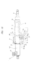
Fig. 1A is a side view of a telescopic steering apparatus according to a first embodiment of the invention, illustrating a state in which a steering column is not compressed. -
Fig. 1B is a side view of the telescopic steering apparatus, illustrating a state in which the steering column is compressed. -
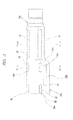
Fig. 2 is a side view of an outer column of the steering column. -
Fig. 3 is a sectional view of the telescopic steering apparatus, which is taken along a line III-III ofFig. 1 . -
Fig. 4 is a sectional view of the outer column, which is taken along a line IV-IV ofFig. 2 . -
Fig. 5 is a sectional view of the outer column, which is taken along a line V-V ofFig. 2 . -
Fig. 6 is a side view of an outer column according to a second embodiment of the invention. -
Fig. 7 is a side view of an outer column according to a third embodiment of the invention. -
Fig. 8 is a side view of an outer column according to a fourth embodiment of the invention. -
Fig. 9 is a side view of an outer column according to a fifth embodiment of the invention. -
Fig. 10 is a side view of an outer column according to a sixth embodiment of the invention. -
Fig. 11 is a partially cut side view illustrating an example of a vehicle steering apparatus having a telescopic steering apparatus mounted thereto. -
Fig. 12 is a sectional view of a telescopic steering apparatus according to a first conventional example, taken along the line XII-XII ofFig. 11 . -
Fig. 13 is a sectional view of a telescopic steering apparatus according to a second conventional example. -
Fig. 14 is a sectional view of a telescopic steering apparatus according to a third conventional example. -
Figs. 1 to 5 show a telescopic steering apparatus according to a first embodiment of the invention. The telescopic steering apparatus has a telescopic mechanism configured to adjust a front-rear position of a steering wheel 1 (seeFig. 11 ) and a tilt mechanism configured to adjust an upper-lower position of thesteering wheel 1, like the structure shown inFigs. 11 and12 . However, the invention is also applicable to a structure having no tilt mechanism. A method of operating the telescopic steering apparatus is similar to that of the telescopic steering apparatus of the related art shown inFigs. 11 and12 . The illustrations and descriptions of parts similar to those of the related art are omitted or simplified. - A
steering column 3a of the telescopic steering apparatus of this embodiment has anouter column 12c configured as an upper column of the steering wheel 1-side (seeFig. 11 ) and aninner column 11c configured as a lower column of a side distant from thesteering wheel 1. - A front end portion of the
outer column 12c has a cylindrical shape and has an elastically enlargeable and reducible inner diameter, and has a supportingportion 36 for fitting and supporting theinner column 11c radially inside theouter column 12c in an axially displaceable manner. The supportingportion 36 has a front supportingportion 37 and arear supporting portion 38. The front supportingportion 37 and therear supporting portion 38 are provided at locations at which they can contact an outer peripheral surface of theinner column 11c even when an axial range in which theouter column 12c and theinner column 11c radially overlap each other is the shortest (in a state where the entire length of thesteering column 3a is maximally extended). - The front supporting
portion 37 has a plurality ofprotuberances outer column 12c. Therespective protuberances outer column 12c, along an axially overlapping range from the front end portion of theouter column 12c to a portion near front ends of column side through-holes movable bracket 22c such that they protrude radially inwards from the inner peripheral surface of theouter column 12c. Distal ends (radially inner ends) of therespective protuberances inner column 11c. - In order to enable the distal ends of the
respective protuberances inner column 11c without increasing the processing accuracy of therespective protuberances protuberances protuberances protuberances outer column 12c. However, theprotuberances - Likewise, the
rear supporting portion 38 has a plurality ofprotuberances outer column 12c. Therespective protuberances outer column 12c, along an axially overlapping range from a portion near rear ends of the column side through-holes movable bracket 22c to a location shifted slightly rearwards from the rear end portions of the column side through-holes 24a such that they protrude radially inwards from the inner peripheral surface of theouter column 12c. In this example, a portion between the front supportingportion 37 and therear supporting portion 38 of the inner peripheral surface of theouter column 12c in the axial direction does not contact the outer peripheral surface of theinner column 11c. However, the supporting portions may be formed to be continuous (the front supporting portion and the rear supporting portion are continuously connected) in the axial direction. - At the mounting state shown in
Fig. 3 , both sides in the width direction (the left-right direction inFig. 3 ) of the outer peripheral surface of theouter column 12c are pressed to the inner side surfaces of theside wall portions bracket 17a. In this way, it is possible to position thesteering column 3a and to secure the flexural stiffness in the width direction. - The inner peripheral surface of the
outer column 12c is provided with ashock absorbing portion 40 at a location shifted toward one side (rear side) in the axial direction from an axial end face of theinner column 11c (an end face on an advancing side seen from theinner column 11c when theinner column 11c and theouter column 12c are relatively displaced in a compression direction, in the present example, the rear end face). As shown inFig. 5 , theshock absorbing portion 40 hasprotuberances outer column 12c. A diameter R40 of an inscribed circle of therespective protuberances inner column 11c. In this example, therespective protuberances shock absorbing portion 40 and therespective protuberances portions 37, 38) are aligned in phase with respect to a circumferential direction. - The
outer column 12c (including the supportingportion 36 and the shock absorbing portion 40) is formed by a hydroforming according to which a fluid pressure (e.g., a hydraulic pressure) is applied to an inner peripheral surface of a metal pipe, a hollow member made of a steel plate material or aluminum alloy material, to plastically deform the metal pipe radially outwards. In order to form theouter column 12c by the hydroforming, a metal pipe is set in a mold having an inner surface shape conforming to an outer surface shape of theouter column 12c that is to be formed by expanding a diameter thereof. Then, both ends of the metal pipe are blocked by a shaft pressing tool and the like and a high fluid pressure is applied into the metal pipe. By the applied fluid pressure, the metal pipe is expanded radially outwards until it firmly contacts an inner surface of a cavity of the mold, so that theouter column 12c is formed. Also, after the forming by the hydroforming, the finishing processing by the cutting work or press is performed for distal ends of therespective protuberances portions 37, 38), as required. The method of forming theouter column 12c is not limited to the hydroforming, and a press working, a bulge forming, a vacuum forming, an air-blow forming, an explosive forming and the like are also possible. - The
movable bracket 22c is integrally formed with theouter column 12c by a hydroforming and has a pair of clampedportions bottom part 42, the clampedportions side wall portions bracket 17a and are displaceable toward and away from each other in the width direction,. The method for forming themovable bracket 22c is not limited to the hydroforming, and may be a press working, a bulge forming, a vacuum forming, an air-blow forming, an explosive forming and the like. - The clamped
portions protuberances Fig. 3 of therespective protuberances portions 37, 38) of theouter column 12c. The column side through-holes portions holes - The
bottom part 42 continuously connects lower ends of the clampedportions Fig. 3 ). The method for integrally forming themovable bracket 22c and theouter column 12c is also not limited to the hydroforming, and may be a press working, a bulge forming, a vacuum forming, an air-blow forming, an explosive forming and the like. - As described above, according to the telescopic steering apparatus of this embodiment, it is possible to implement the structure capable of stably maintaining the
inner column 11c radially inside theouter column 12c and absorbing a shock load upon a secondary collision at low cost. First, the reason to implement the structure capable of stably maintaining theinner column 11c radially inside theouter column 12c at low cost is because theouter column 12c including the supporting portion 36 (the front and rear supportingportions 37, 38) for supporting theinner column 11c and themovable bracket 22c are integrally formed by the hydroforming. That is, even with the structure where the supporting portion 36 (the front and rear supportingportions 37, 38) is configured by the multiple (for example, three or more)respective protuberances - The reason why the structure capable of absorbing the shock load upon secondary collision can be implemented at low cost is because the inner peripheral surface of the
outer column 12c is provided with theshock absorbing portion 40, the diameter of the inscribed circle of which is smaller than the outer diameter of theinner column 11c, at a location shifted toward one side in the axial direction from the axial end face of theinner column 11c, and theshock absorbing portion 40 is formed simultaneously with therespective protuberances inner column 11c and theouter column 12c are relatively displaced in the direction in which thesteering column 3a is compressed (seeFig. 1B ) such that the axial end face (rear end) of theinner column 11c frictionally moves along theshock absorbing portion 40 of theouter column 12c. Theshock absorbing portion 40 functions as a resistance against the relative displacement of theinner column 11c and theouter column 12c and thus absorbs the shock energy applied to the steering wheel upon the secondary collision. Since theshock absorbing portion 40 is directly formed at theouter column 12c, it is not necessary to provide a separate shock absorption member. As a result, it is possible to reduce the processing cost, the component management cost and the assembling cost. - The supporting portion 36 (the front and rear supporting
portions 37, 38) provided on the inner peripheral surface of theouter column 12c and the outer peripheral surface of theinner column 11c overlapping the supportingportion 36 contact each other at three locations along the circumferential direction. Therefore, therespective protuberances inner column 11c without increasing the processing accuracy of therespective protuberances portion 36. - When sufficient processing accuracy of the supporting portion 36 (the front and rear supporting
portions 37, 38) cannot be obtained only with the hydroforming, the finishing processing by cutting work or press is performed for the distal ends of therespective protuberances portion 36. Even when the finishing processing is performed, since only the threeprotuberances protuberances inner column 11c can be stably supported by the supporting portion 36 (the front and rear supportingportions 37, 38). Therespective protuberances portions 37, 38) are formed to have the mountain-like shape by the hydroforming. Therefore, compared to the structure of the related art shown inFig. 14 , it is possible to increase the stiffness for supporting theinner column 11c. The other structures and operations are the same as the steering apparatus of the related art as described above. -
Fig. 6 shows anouter column 12d of a telescopic steering apparatus according to a second embodiment of the invention. Like the first embodiment, therespective protuberances portions 37, 38) of theouter column 12d and theprotuberances shock absorbing portion 40 are aligned in phase with respect to the circumferential direction. The axial rear ends of therespective protuberances rear supporting portion 38 and the axial front ends of theprotuberances shock absorbing portion 40 are smoothly continued by continuingparts inner column 11c (seeFigs. 1 and3 ) and theouter column 12d can be smoothly and stably compressed. As a result, it is possible to stably absorb the shock load upon the secondary collision. The other structures, operations and effects are similar to those of the first embodiment. -
Fig. 7 shows anouter column 12e of a telescopic steering apparatus according to a third embodiment of the invention. Therespective protuberances portions 37, 38) of theouter column 12e are provided in a similar manner as in the above embodiment (seeFigs. 1 to 4 ).Respective protuberances shock absorbing portion 40a are provided at locations (the upper and lower locations are opposite to the above embodiment) that are symmetric to the supporting portion 36 (the front and rear supportingportions 37, 38) with respect to a virtual plane α passing through a central axis O36 of an inscribed circle X36 (seeFig. 4 ) of the supportingportion 36 and perpendicular to theside wall portions bracket 17a. - According to the telescopic steering apparatus, it is possible to increase the contacting locations along the circumferential direction (in the present example, six locations) between the
respective protuberances portions 37, 38) andrespective protuberances shock absorbing portion 40a and the outer peripheral surface of theinner column 11c, when theinner column 11c (seeFigs. 1 and3 ) and theouter column 12e are compressed and thus the end face of theinner column 11c frictionally moves therespective protuberances shock absorbing portion 40a (in a state in which the shock load is absorbed). As a result, it is possible to further sufficiently suppress the relative inclination of theinner column 11c and theouter column 12e, based on the load of the complex directions applied to theinner column 11c and theouter column 12e. The other structures, operations and effects are similar to those of the above embodiments. -
Fig. 8 shows anouter column 12f of a telescopic steering apparatus according to a fourth embodiment of the invention. Therespective protuberances portions 37, 38) of theouter column 12f are provided in a similar manner as in the fourth embodiment (seeFigs. 1 to 4 ).Respective protuberances shock absorbing portion 40b are provided at two positions circumferentially equally spaced on an inner peripheral surface of theouter column 12f (in the present example, at upper and lower ends in a state mouthed on the vehicle). - According to the telescopic steering apparatus, the number (two along the circumferential direction) of the
respective protuberances shock absorbing portion 40b is smaller than the above embodiments (three along the circumferential direction). Therefore, it is possible to reduce a resistance force when theinner column 11c (seeFigs. 1 and3 ) and theouter column 12f are compressed and thus the end face of theinner column 11c frictionally moves along therespective protuberances shock absorbing portion 40b. The other structures, operations and effects are similar to those of the above embodiments. -
Fig. 9 shows anouter column 12g of a telescopic steering apparatus according to a fifth embodiment of the invention. Therespective protuberances portions 37, 38) of theouter column 12g are provided in a similar manner as in the first to third embodiments (seeFigs. 1 to 4 ).Respective protuberances shock absorbing portion 40c are provided at four locations along the circumferential direction on an inner peripheral surface of theouter column 12g (at positions that are inclined by about 30° in the upper-lower direction relative to the virtual plane α passing through the central axis O36 of the inscribed circle X36 (seeFig. 4 ) of the supporting portion 36 (the front and rear supportingportions 37, 38) and perpendicular to theside wall portions bracket 17a (seeFigs. 3 and4 ). - According to the above telescopic steering apparatus, the number (four along the circumferential direction) of the
respective protuberances shock absorbing portion 40c is larger than the above embodiments (three along the circumferential direction). Therefore, it is possible to increase a resistance force when theinner column 11c (seeFigs. 1 and3 ) and theouter column 12g are compressed and thus the end surface of theinner column 11c frictionally moves along therespective protuberances shock absorbing portion 40c. - It is possible to increase the contacting locations along the circumferential direction (in the present example, seven locations in the circumferential direction,) between the
respective protuberances portions 37, 38) andrespective protuberances shock absorbing portion 40c and the outer peripheral surface of theinner column 11c, when theinner column 11c and theouter column 12g are compressed and thus the end face of theinner column 11c frictionally moves along therespective protuberances shock absorbing portion 40c (in a state in which the shock load is absorbed). As a result, it is possible to prevent the relative inclination of theinner column 11c and theouter column 12g, based on the load of the complex directions applied to theinner column 11c and theouter column 12g, thereby stably absorbing the shock. The other structures, operations and effects are similar to those of the first to third embodiments. -
Fig. 10 shows a telescopic steering apparatus according to a sixth embodiment of the invention. The telescopic steering apparatus of this embodiment is different from the telescopic steering apparatus of the first embodiment, in that first and secondfrictional plates movable bracket 22d is designed so as to provide the first and secondfrictional plates - Like the above embodiments, an
outer column 12h forming the telescopic steering apparatus of this embodiment has a cylinder shape, an inner diameter of at least a portion in the axial direction is elastically enlargeable and reducible, and has a supportingportion 36a for fitting and supporting theinner column 11c radially inside theouter column 12h in an axially displaceable manner. The supportingportion 36a is configured by afront supporting portion 37a and arear supporting portion 38a. The axial positions of the front supportingportion 37a and therear supporting portion 38a are the same as the structure of the first embodiment. -
Protuberances Fig. 9 ofrespective protuberances portions inner column 11c contact each other at locations that are inclined by an angle θ (in the present example, 30°) towards themovable bracket 22d (towards the lower side inFig. 10 ) with respect to a virtual plane β including a central axis O11 of theinner column 11c and perpendicular to theside wall portions bracket 17a. When the angle θ is made to be larger (a size in the width direction between theprotuberances Fig. 10 is made to be smaller), it is possible to increase the support stiffness of theouter column 12h in the upper-lower direction and to improve forming of themovable bracket 22d. However, when the angle θ is made to be excessively large, the support stiffness in the width direction is lowered. Hence, a magnitude of the angle θ is appropriately determined, considering the support stiffness required in the respective directions, thicknesses of firstfrictional plates frictional plates - In the present example, the
movable bracket 22d has a pair of clampedportions bottom part 42a connecting lower ends of the clampedportions portions outer column 12h and held between the inner side surfaces of theside wall portions side wall portions bracket 17a is widened or narrowed. The clampedportions outer column 12h from lower ends of theprotuberances holes portions - A size W in the width direction between the inner side surfaces of the
side wall portions bracket 17a in the width direction is substantially the same as a sum of a length D between outer side surfaces of the clampedportions Fig. 9 ) and a summed thickness 2T45 of the first and secondfrictional plates 44, 45 (W ≈ D + 2T45). The firstfrictional plates frictional plates side wall portions portions - Each of the first
frictional plates frictional plates holes 46 into which therod member 26 can be inserted and which are elongated in the front-rear direction, at locations at which at least the column side through-holes portions frictional plates portions frictional plates movable bracket 22d so that they can be moved in conjunction with themovable bracket 22d in the front-rear and upper-lower directions. - Each of the second
frictional plates frictional plate parts part 48 that continues lower end portions of thefrictional plate parts frictional plates frictional plate parts holes rod member 26 can be inserted without play is formed. That is, in a state in which therod member 26 is inserted into the second frictional plate side through-holes frictional plates rod member 26 and therod member 26 can be axially displaced. - The respective first
frictional plates frictional plates side wall portions portions frictional plate frictional plate parts frictional plates part 48 of the one secondfrictional plate - The
outer column 12h and the respective first and secondfrictional plates Fig. 10 . At the state where the respective members are assembled as shown inFig. 10 , when positioning the steering wheel 1 (seeFig. 11 ) in the front-rear direction, the adjustinglever 27 is rotated in a predetermined direction, like the structure of the related art as described above, thereby elastically widening the gap between the inner side surfaces of theside wall portions side wall portions frictional plates frictional plates portions portion 36a (the front supportingportion 37a and therear supporting portion 38a) of theouter column 12h and the outer peripheral surface of theinner column 11c is lowered or lost, so that theinner column 11c and theouter column 12h can be relatively displaced in the axial direction (the front-rear direction). As a result, it is possible to position thesteering wheel 1 in the front-rear direction and the upper-lower direction. - After the positioning, when the adjusting
lever 27 is rotated in the reverse direction to the predetermined direction, the gap between the inner side surfaces of theside wall portions side wall portions frictional plates frictional plates portions portion 36a (the front supportingportion 37a and therear supporting portion 38a) of theouter column 12h and the outer peripheral surface of theinner column 11c is increased. As a result, thesteering wheel 1 is supported at an adjusted position. In the operation for supporting thesteering wheel 1 at the adjusted position, in the addition to the clampedportions side wall portions frictional plates outer column 12h in the width direction may also be pressed by the inner side surfaces of theside wall portions outer column 12h. - According to the telescopic steering apparatus of this embodiment, the first
frictional plates frictional plates side wall portions portions side wall portions frictional plates frictional plates portions steering wheel 1 at the adjusted position. The present embodiment can be combined with the above respective embodiments. The other structures, operations and effects are similar to those of the first embodiment. - The application is based on a Japanese Patent Application No.
2012-184113 filed on August 23, 2012 - The above embodiments have been described in connection with a steering apparatus including a telescopic mechanism configured to adjust a front-rear position of a steering wheel and a tilt mechanism configured to adjust an upper-lower position of the steering wheel. However, the present invention is also applicable to a steering apparatus having only the telescopic mechanism. Also, the positional relation of the outer column and inner column of the steering column in the front-rear direction is irrelevant. Contrary to the illustrated examples, the inner column may be provided on the rear side and the outer column may be provided on the front side.
-
- 1: Steering Wheel
- 2: Steering Shaft
- 3, 3a: Steering Column
- 11, 11a, 11b, 11c: Inner Column
- 12, 12a, 12b, 12c, 12d, 12e, 12f, 12g, 12h: Outer Column
- 14: Vehicle Body
- 17, 17a: Fixed Bracket
- 18, 18a: Side Wall Portion
- 22, 22a, 22c, 22d: Movable bracket
- 23, 23a, 23b, 23c: Clamped Portion
- 24, 24a, 24b: Column Side Through-Hole
- 25: Vehicle Body Side Through-Hole
- 26: Rod Member
- 27: Adjusting Lever
- 36, 36a: Supporting Portion
- 37, 37a: Front Supporting Portion
- 38, 38a: Rear Supporting Portion
- 30, 30a, 40b, 40c: Shock Absorbing Portion
- 41, 41a, 41b, 41c: Protuberance
Claims (9)
- A telescopic steering apparatus comprising a telescopic steering column, a steering shaft, a fixed bracket configured to be fixed to a vehicle body, a movable bracket, a rod member, and an adjusting lever,
wherein the steering column comprises a cylindrical outer column, at least a portion of which in an axial direction having an enlargeable and reducible inner diameter, and a cylindrical inner column arranged radially inside the outer column, the outer column and the inner column being configured to be telescopically combined, and an inner peripheral surface of the outer column having a supporting portion to which the inner column is fitted and is arranged to support the inner column such that the inner column is axially displaceable,
wherein the steering shaft is rotatably supported radially inside the steering column, and has a rear end portion protruding rearward from a rear end opening of the steering column and configured such that a steering wheel is attached thereto,
wherein the fixed bracket includes a pair of side wall portions provided at a fixed part so as to hold the portion of the outer column having the enlargeable and reducible inner diameter from both sides in a width direction, the pair of side wall portions being displaceable toward and away from each other in the width direction,
wherein the movable bracket has a pair of clamped portions formed integrally with the outer column by plastic forming, the pair of clamped portions being displaceable toward and away from each other in the width direction in accordance with a displacement of the pair of side wall portions toward and away from each other in the width direction,
wherein the rod member is arranged in the width direction such that the rod member is inserted into vehicle body side through-holes formed through the pair of side wall portions at locations aligned with each other and column side through-holes formed through the pair of clamped portions, and is configured to widen or to narrow a gap between a pair of surfaces of the pair of side wall portions opposed to each other,
wherein the adjusting lever is provided at a base end portion of the rod member, and is configured to widen or to narrow the gap between the pair of surfaces by a rotation of the adjusting lever,
wherein the inner peripheral surface of the outer column has a shock absorbing portion at a location shifted toward one side in the axial direction from an axial end face of the inner column, a diameter of an inscribed circle of the shock absorbing portion being smaller than an outer diameter of the inner column,
wherein the outer column, including the supporting portion and the shock absorbing portion, is formed by expanding a hollow pipe radially outwards, and
wherein the movable bracket is formed integrally with the outer column by an expansion forming. - The telescopic steering apparatus according to claim 1, wherein the expansion forming is a hydroforming.
- The telescopic steering apparatus according to claim 1 or 2, wherein the supporting portion of the outer column and the outer peripheral surface of the inner column contact each other at three or more locations along a circumferential direction.
- The telescopic steering apparatus according to any one of claims 1 to 3, wherein the supporting portion of the outer column and the outer peripheral surface of the inner column contact each other at only three locations along a circumferential direction.
- The telescopic steering apparatus according to any one of claims 1 to 4, wherein the supporting portion of the outer column is finished by a cutting or a pressing.
- The telescopic steering apparatus according to any one of claims 1 to 5, wherein the shock absorbing portion includes protuberances protruding radially inwards from the inner peripheral surface of the outer column at a plurality of locations along a circumferential direction on the inner peripheral surface of the outer column.
- The telescopic steering apparatus according to any one of claims 1 to 6, wherein the supporting portion and the shock absorbing portion are aligned in phase with respect to a circumferential direction.
- The telescopic steering apparatus according to claim 7, wherein the supporting portion and the shock absorbing portion are provided continuously in the axial direction.
- The telescopic steering apparatus according to any one of claims 1 to 6, wherein the shock absorbing portion is provided at a location symmetric to the supporting portion with respect to a virtual plane including a central axis of an inscribed circle of the supporting portion and perpendicular to the pair of side wall portions of the fixed bracket.
Applications Claiming Priority (2)
| Application Number | Priority Date | Filing Date | Title |
|---|---|---|---|
| JP2012184113A JP6003395B2 (en) | 2012-08-23 | 2012-08-23 | Telescopic steering device |
| PCT/JP2013/072446 WO2014030713A1 (en) | 2012-08-23 | 2013-08-22 | Telescopic steering device |
Publications (3)
| Publication Number | Publication Date |
|---|---|
| EP2889203A1 true EP2889203A1 (en) | 2015-07-01 |
| EP2889203A4 EP2889203A4 (en) | 2016-05-11 |
| EP2889203B1 EP2889203B1 (en) | 2017-05-31 |
Family
ID=50150017
Family Applications (1)
| Application Number | Title | Priority Date | Filing Date |
|---|---|---|---|
| EP13831811.8A Not-in-force EP2889203B1 (en) | 2012-08-23 | 2013-08-22 | Telescopic steering device |
Country Status (5)
| Country | Link |
|---|---|
| US (1) | US9365234B2 (en) |
| EP (1) | EP2889203B1 (en) |
| JP (1) | JP6003395B2 (en) |
| CN (1) | CN103874619B (en) |
| WO (1) | WO2014030713A1 (en) |
Families Citing this family (10)
| Publication number | Priority date | Publication date | Assignee | Title |
|---|---|---|---|---|
| JP2016055689A (en) * | 2014-09-08 | 2016-04-21 | 富士機工株式会社 | Electric steering column device |
| JP6447871B2 (en) * | 2015-03-25 | 2019-01-09 | 株式会社ジェイテクト | Steering device |
| US9789897B2 (en) * | 2015-08-11 | 2017-10-17 | Yamada Manufacturing Co., Ltd. | Steering apparatus |
| US10065671B2 (en) | 2015-10-21 | 2018-09-04 | Nsk Ltd. | Telescopic steering column and steering device |
| EP3315381B1 (en) * | 2015-10-22 | 2020-03-11 | NSK Ltd. | Outer column with bracket, steering column with bracket, and steering device |
| JP2017140976A (en) * | 2016-02-12 | 2017-08-17 | 株式会社ジェイテクト | Steering column device |
| JP6753737B2 (en) * | 2016-08-31 | 2020-09-09 | 株式会社山田製作所 | Steering device |
| JP6921562B2 (en) * | 2017-03-06 | 2021-08-18 | 株式会社山田製作所 | Steering device |
| JP6916072B2 (en) * | 2017-09-12 | 2021-08-11 | 株式会社山田製作所 | Steering device |
| CN113041750A (en) * | 2021-02-07 | 2021-06-29 | 机械工业第九设计研究院有限公司 | Automatic cleaning system for coated car body three-dimensional warehouse |
Family Cites Families (28)
| Publication number | Priority date | Publication date | Assignee | Title |
|---|---|---|---|---|
| FR2586987B1 (en) * | 1985-09-06 | 1990-06-01 | Peugeot Cycles | TELESCOPIC SUB-ASSEMBLY FOR STEERING COLUMN |
| JPH03128564U (en) * | 1990-04-10 | 1991-12-25 | ||
| JPH0665149U (en) * | 1993-02-26 | 1994-09-13 | 黒石鉄工株式会社 | Energy absorption type steering device |
| KR19980058889A (en) * | 1996-12-30 | 1998-10-07 | 오상수 | Shock Absorber of Vehicle Steering Column |
| JP3827865B2 (en) | 1998-06-16 | 2006-09-27 | 株式会社日本製鋼所 | LASER PROCESSING DEVICE AND METHOD FOR CONTROLLING THE LASER PROCESSING DEVICE |
| JP3788039B2 (en) * | 1998-06-19 | 2006-06-21 | 日本精工株式会社 | Shock absorbing steering column device |
| JP3791222B2 (en) * | 1999-01-27 | 2006-06-28 | 日本精工株式会社 | Tilt-type steering device |
| JP2002053048A (en) * | 2000-08-11 | 2002-02-19 | Nsk Ltd | Vehicle steering system |
| JP3940319B2 (en) * | 2002-06-05 | 2007-07-04 | 株式会社ジェイテクト | Shock absorbing steering device |
| JP2004066925A (en) * | 2002-08-05 | 2004-03-04 | Nsk Ltd | Steering column device |
| US20050077716A1 (en) * | 2003-10-08 | 2005-04-14 | Urista Jesus Raul Garcia | Steering column energy absorber |
| US7784830B2 (en) * | 2003-10-23 | 2010-08-31 | Chrysler Group Llc | Axially adjustable steering column assembly with flexible bearing sleeve |
| JP2005219641A (en) * | 2004-02-05 | 2005-08-18 | Nsk Ltd | Steering column device |
| WO2005120930A1 (en) * | 2004-06-11 | 2005-12-22 | Nsk Ltd. | Impact absorbing steering column device and electrically driven power steering device |
| JP2006232103A (en) * | 2005-02-25 | 2006-09-07 | Nsk Ltd | Shock absorption steering column device and electric power steering device |
| JP2005349968A (en) | 2004-06-11 | 2005-12-22 | Nsk Ltd | Shock absorption steering column device and electric power steering device |
| JP4609203B2 (en) * | 2004-08-05 | 2011-01-12 | 日本精工株式会社 | Steering column device |
| JP4879596B2 (en) * | 2005-02-15 | 2012-02-22 | 日本精工株式会社 | Method for producing metal member having through hole |
| JP5119707B2 (en) * | 2006-06-29 | 2013-01-16 | 日本精工株式会社 | Telescopic shaft |
| JP2008302751A (en) * | 2007-06-06 | 2008-12-18 | Nsk Ltd | Steering column device |
| JP5369537B2 (en) * | 2008-08-08 | 2013-12-18 | アイシン精機株式会社 | Energy absorbing steering column |
| JP5328325B2 (en) * | 2008-12-05 | 2013-10-30 | 富士機工株式会社 | Steering column device |
| JP2011105122A (en) * | 2009-11-17 | 2011-06-02 | Nsk Ltd | Steering device for vehicle |
| JP5146483B2 (en) * | 2010-04-08 | 2013-02-20 | 日本精工株式会社 | Steering column device |
| DE102010020088B4 (en) * | 2010-05-10 | 2013-06-27 | Thyssenkrupp Presta Aktiengesellschaft | Method and device for controlling a controllable energy absorber |
| CN105128926B (en) | 2011-02-02 | 2017-12-19 | 日本精工株式会社 | Electric type power steering device pole unit |
| CN104908801B (en) * | 2011-02-25 | 2017-08-01 | 日本精工株式会社 | Telescopic steering apparatus |
| WO2013094305A1 (en) * | 2011-12-20 | 2013-06-27 | 日本精工株式会社 | Steering device |
-
2012
- 2012-08-23 JP JP2012184113A patent/JP6003395B2/en active Active
-
2013
- 2013-08-22 US US14/353,923 patent/US9365234B2/en active Active
- 2013-08-22 EP EP13831811.8A patent/EP2889203B1/en not_active Not-in-force
- 2013-08-22 WO PCT/JP2013/072446 patent/WO2014030713A1/en not_active Ceased
- 2013-08-22 CN CN201380001901.6A patent/CN103874619B/en active Active
Also Published As
| Publication number | Publication date |
|---|---|
| CN103874619A (en) | 2014-06-18 |
| CN103874619B (en) | 2016-10-12 |
| WO2014030713A1 (en) | 2014-02-27 |
| US20150151776A1 (en) | 2015-06-04 |
| JP6003395B2 (en) | 2016-10-05 |
| JP2014040206A (en) | 2014-03-06 |
| EP2889203B1 (en) | 2017-05-31 |
| US9365234B2 (en) | 2016-06-14 |
| EP2889203A4 (en) | 2016-05-11 |
Similar Documents
| Publication | Publication Date | Title |
|---|---|---|
| EP2889203B1 (en) | Telescopic steering device | |
| JP5614449B2 (en) | Automotive steering device | |
| JP5428582B2 (en) | Steering device | |
| EP1762462A1 (en) | Steering apparatus | |
| US10940881B2 (en) | Steering device | |
| JP5561253B2 (en) | Steering device | |
| JP5783294B2 (en) | Steering column | |
| EP2786914B1 (en) | Steering device | |
| JP5146407B2 (en) | Steering device | |
| JP5668832B2 (en) | Telescopic steering device | |
| JP5725140B2 (en) | Telescopic steering device | |
| JP5408214B2 (en) | Telescopic steering device | |
| JP5494587B2 (en) | Telescopic steering device | |
| US11447170B2 (en) | Steering column and steering device | |
| JP5725139B2 (en) | Telescopic steering device | |
| JP5464184B2 (en) | Telescopic steering device | |
| JP5725141B2 (en) | Telescopic steering device | |
| JP2015214320A (en) | Telescopic steering device | |
| JP2014088124A (en) | Telescopic steering device | |
| JP2014061745A (en) | Telescopic steering device | |
| JP2015214319A (en) | Telescopic steering device | |
| JP2008239028A (en) | Steering device |
Legal Events
| Date | Code | Title | Description |
|---|---|---|---|
| PUAI | Public reference made under article 153(3) epc to a published international application that has entered the european phase |
Free format text: ORIGINAL CODE: 0009012 |
|
| 17P | Request for examination filed |
Effective date: 20140425 |
|
| AK | Designated contracting states |
Kind code of ref document: A1 Designated state(s): AL AT BE BG CH CY CZ DE DK EE ES FI FR GB GR HR HU IE IS IT LI LT LU LV MC MK MT NL NO PL PT RO RS SE SI SK SM TR |
|
| AX | Request for extension of the european patent |
Extension state: BA ME |
|
| DAX | Request for extension of the european patent (deleted) | ||
| RA4 | Supplementary search report drawn up and despatched (corrected) |
Effective date: 20160407 |
|
| RIC1 | Information provided on ipc code assigned before grant |
Ipc: B21D 53/88 20060101ALI20160401BHEP Ipc: B21D 26/033 20110101ALI20160401BHEP Ipc: B62D 1/19 20060101AFI20160401BHEP Ipc: B60R 21/05 20060101ALI20160401BHEP |
|
| GRAP | Despatch of communication of intention to grant a patent |
Free format text: ORIGINAL CODE: EPIDOSNIGR1 |
|
| INTG | Intention to grant announced |
Effective date: 20170120 |
|
| GRAS | Grant fee paid |
Free format text: ORIGINAL CODE: EPIDOSNIGR3 |
|
| GRAA | (expected) grant |
Free format text: ORIGINAL CODE: 0009210 |
|
| AK | Designated contracting states |
Kind code of ref document: B1 Designated state(s): AL AT BE BG CH CY CZ DE DK EE ES FI FR GB GR HR HU IE IS IT LI LT LU LV MC MK MT NL NO PL PT RO RS SE SI SK SM TR |
|
| REG | Reference to a national code |
Ref country code: CH Ref legal event code: EP Ref country code: GB Ref legal event code: FG4D |
|
| REG | Reference to a national code |
Ref country code: AT Ref legal event code: REF Ref document number: 897169 Country of ref document: AT Kind code of ref document: T Effective date: 20170615 |
|
| REG | Reference to a national code |
Ref country code: IE Ref legal event code: FG4D |
|
| REG | Reference to a national code |
Ref country code: DE Ref legal event code: R096 Ref document number: 602013021827 Country of ref document: DE |
|
| REG | Reference to a national code |
Ref country code: FR Ref legal event code: PLFP Year of fee payment: 5 |
|
| REG | Reference to a national code |
Ref country code: NL Ref legal event code: MP Effective date: 20170531 |
|
| REG | Reference to a national code |
Ref country code: LT Ref legal event code: MG4D |
|
| REG | Reference to a national code |
Ref country code: AT Ref legal event code: MK05 Ref document number: 897169 Country of ref document: AT Kind code of ref document: T Effective date: 20170531 |
|
| PG25 | Lapsed in a contracting state [announced via postgrant information from national office to epo] |
Ref country code: NO Free format text: LAPSE BECAUSE OF FAILURE TO SUBMIT A TRANSLATION OF THE DESCRIPTION OR TO PAY THE FEE WITHIN THE PRESCRIBED TIME-LIMIT Effective date: 20170831 Ref country code: HR Free format text: LAPSE BECAUSE OF FAILURE TO SUBMIT A TRANSLATION OF THE DESCRIPTION OR TO PAY THE FEE WITHIN THE PRESCRIBED TIME-LIMIT Effective date: 20170531 Ref country code: ES Free format text: LAPSE BECAUSE OF FAILURE TO SUBMIT A TRANSLATION OF THE DESCRIPTION OR TO PAY THE FEE WITHIN THE PRESCRIBED TIME-LIMIT Effective date: 20170531 Ref country code: AT Free format text: LAPSE BECAUSE OF FAILURE TO SUBMIT A TRANSLATION OF THE DESCRIPTION OR TO PAY THE FEE WITHIN THE PRESCRIBED TIME-LIMIT Effective date: 20170531 Ref country code: FI Free format text: LAPSE BECAUSE OF FAILURE TO SUBMIT A TRANSLATION OF THE DESCRIPTION OR TO PAY THE FEE WITHIN THE PRESCRIBED TIME-LIMIT Effective date: 20170531 Ref country code: GR Free format text: LAPSE BECAUSE OF FAILURE TO SUBMIT A TRANSLATION OF THE DESCRIPTION OR TO PAY THE FEE WITHIN THE PRESCRIBED TIME-LIMIT Effective date: 20170901 Ref country code: LT Free format text: LAPSE BECAUSE OF FAILURE TO SUBMIT A TRANSLATION OF THE DESCRIPTION OR TO PAY THE FEE WITHIN THE PRESCRIBED TIME-LIMIT Effective date: 20170531 |
|
| PG25 | Lapsed in a contracting state [announced via postgrant information from national office to epo] |
Ref country code: RS Free format text: LAPSE BECAUSE OF FAILURE TO SUBMIT A TRANSLATION OF THE DESCRIPTION OR TO PAY THE FEE WITHIN THE PRESCRIBED TIME-LIMIT Effective date: 20170531 Ref country code: IS Free format text: LAPSE BECAUSE OF FAILURE TO SUBMIT A TRANSLATION OF THE DESCRIPTION OR TO PAY THE FEE WITHIN THE PRESCRIBED TIME-LIMIT Effective date: 20170930 Ref country code: NL Free format text: LAPSE BECAUSE OF FAILURE TO SUBMIT A TRANSLATION OF THE DESCRIPTION OR TO PAY THE FEE WITHIN THE PRESCRIBED TIME-LIMIT Effective date: 20170531 Ref country code: SE Free format text: LAPSE BECAUSE OF FAILURE TO SUBMIT A TRANSLATION OF THE DESCRIPTION OR TO PAY THE FEE WITHIN THE PRESCRIBED TIME-LIMIT Effective date: 20170531 Ref country code: LV Free format text: LAPSE BECAUSE OF FAILURE TO SUBMIT A TRANSLATION OF THE DESCRIPTION OR TO PAY THE FEE WITHIN THE PRESCRIBED TIME-LIMIT Effective date: 20170531 Ref country code: BG Free format text: LAPSE BECAUSE OF FAILURE TO SUBMIT A TRANSLATION OF THE DESCRIPTION OR TO PAY THE FEE WITHIN THE PRESCRIBED TIME-LIMIT Effective date: 20170831 |
|
| PG25 | Lapsed in a contracting state [announced via postgrant information from national office to epo] |
Ref country code: DK Free format text: LAPSE BECAUSE OF FAILURE TO SUBMIT A TRANSLATION OF THE DESCRIPTION OR TO PAY THE FEE WITHIN THE PRESCRIBED TIME-LIMIT Effective date: 20170531 Ref country code: CZ Free format text: LAPSE BECAUSE OF FAILURE TO SUBMIT A TRANSLATION OF THE DESCRIPTION OR TO PAY THE FEE WITHIN THE PRESCRIBED TIME-LIMIT Effective date: 20170531 Ref country code: SK Free format text: LAPSE BECAUSE OF FAILURE TO SUBMIT A TRANSLATION OF THE DESCRIPTION OR TO PAY THE FEE WITHIN THE PRESCRIBED TIME-LIMIT Effective date: 20170531 Ref country code: RO Free format text: LAPSE BECAUSE OF FAILURE TO SUBMIT A TRANSLATION OF THE DESCRIPTION OR TO PAY THE FEE WITHIN THE PRESCRIBED TIME-LIMIT Effective date: 20170531 Ref country code: EE Free format text: LAPSE BECAUSE OF FAILURE TO SUBMIT A TRANSLATION OF THE DESCRIPTION OR TO PAY THE FEE WITHIN THE PRESCRIBED TIME-LIMIT Effective date: 20170531 |
|
| PG25 | Lapsed in a contracting state [announced via postgrant information from national office to epo] |
Ref country code: PL Free format text: LAPSE BECAUSE OF FAILURE TO SUBMIT A TRANSLATION OF THE DESCRIPTION OR TO PAY THE FEE WITHIN THE PRESCRIBED TIME-LIMIT Effective date: 20170531 Ref country code: IT Free format text: LAPSE BECAUSE OF FAILURE TO SUBMIT A TRANSLATION OF THE DESCRIPTION OR TO PAY THE FEE WITHIN THE PRESCRIBED TIME-LIMIT Effective date: 20170531 Ref country code: SM Free format text: LAPSE BECAUSE OF FAILURE TO SUBMIT A TRANSLATION OF THE DESCRIPTION OR TO PAY THE FEE WITHIN THE PRESCRIBED TIME-LIMIT Effective date: 20170531 |
|
| REG | Reference to a national code |
Ref country code: DE Ref legal event code: R097 Ref document number: 602013021827 Country of ref document: DE |
|
| REG | Reference to a national code |
Ref country code: CH Ref legal event code: PL |
|
| PG25 | Lapsed in a contracting state [announced via postgrant information from national office to epo] |
Ref country code: MC Free format text: LAPSE BECAUSE OF FAILURE TO SUBMIT A TRANSLATION OF THE DESCRIPTION OR TO PAY THE FEE WITHIN THE PRESCRIBED TIME-LIMIT Effective date: 20170531 |
|
| PLBE | No opposition filed within time limit |
Free format text: ORIGINAL CODE: 0009261 |
|
| STAA | Information on the status of an ep patent application or granted ep patent |
Free format text: STATUS: NO OPPOSITION FILED WITHIN TIME LIMIT |
|
| PG25 | Lapsed in a contracting state [announced via postgrant information from national office to epo] |
Ref country code: LI Free format text: LAPSE BECAUSE OF NON-PAYMENT OF DUE FEES Effective date: 20170831 Ref country code: CH Free format text: LAPSE BECAUSE OF NON-PAYMENT OF DUE FEES Effective date: 20170831 |
|
| 26N | No opposition filed |
Effective date: 20180301 |
|
| REG | Reference to a national code |
Ref country code: IE Ref legal event code: MM4A |
|
| PG25 | Lapsed in a contracting state [announced via postgrant information from national office to epo] |
Ref country code: SI Free format text: LAPSE BECAUSE OF FAILURE TO SUBMIT A TRANSLATION OF THE DESCRIPTION OR TO PAY THE FEE WITHIN THE PRESCRIBED TIME-LIMIT Effective date: 20170531 |
|
| REG | Reference to a national code |
Ref country code: BE Ref legal event code: MM Effective date: 20170831 |
|
| PG25 | Lapsed in a contracting state [announced via postgrant information from national office to epo] |
Ref country code: LU Free format text: LAPSE BECAUSE OF NON-PAYMENT OF DUE FEES Effective date: 20170822 |
|
| REG | Reference to a national code |
Ref country code: FR Ref legal event code: PLFP Year of fee payment: 6 |
|
| PG25 | Lapsed in a contracting state [announced via postgrant information from national office to epo] |
Ref country code: IE Free format text: LAPSE BECAUSE OF NON-PAYMENT OF DUE FEES Effective date: 20170822 |
|
| PG25 | Lapsed in a contracting state [announced via postgrant information from national office to epo] |
Ref country code: BE Free format text: LAPSE BECAUSE OF NON-PAYMENT OF DUE FEES Effective date: 20170831 |
|
| PG25 | Lapsed in a contracting state [announced via postgrant information from national office to epo] |
Ref country code: MT Free format text: LAPSE BECAUSE OF NON-PAYMENT OF DUE FEES Effective date: 20170822 |
|
| PG25 | Lapsed in a contracting state [announced via postgrant information from national office to epo] |
Ref country code: HU Free format text: LAPSE BECAUSE OF FAILURE TO SUBMIT A TRANSLATION OF THE DESCRIPTION OR TO PAY THE FEE WITHIN THE PRESCRIBED TIME-LIMIT; INVALID AB INITIO Effective date: 20130822 |
|
| PG25 | Lapsed in a contracting state [announced via postgrant information from national office to epo] |
Ref country code: CY Free format text: LAPSE BECAUSE OF FAILURE TO SUBMIT A TRANSLATION OF THE DESCRIPTION OR TO PAY THE FEE WITHIN THE PRESCRIBED TIME-LIMIT Effective date: 20170531 |
|
| PGFP | Annual fee paid to national office [announced via postgrant information from national office to epo] |
Ref country code: FR Payment date: 20190711 Year of fee payment: 7 |
|
| PG25 | Lapsed in a contracting state [announced via postgrant information from national office to epo] |
Ref country code: MK Free format text: LAPSE BECAUSE OF FAILURE TO SUBMIT A TRANSLATION OF THE DESCRIPTION OR TO PAY THE FEE WITHIN THE PRESCRIBED TIME-LIMIT Effective date: 20170531 |
|
| PGFP | Annual fee paid to national office [announced via postgrant information from national office to epo] |
Ref country code: GB Payment date: 20190822 Year of fee payment: 7 |
|
| PG25 | Lapsed in a contracting state [announced via postgrant information from national office to epo] |
Ref country code: TR Free format text: LAPSE BECAUSE OF FAILURE TO SUBMIT A TRANSLATION OF THE DESCRIPTION OR TO PAY THE FEE WITHIN THE PRESCRIBED TIME-LIMIT Effective date: 20170531 |
|
| PG25 | Lapsed in a contracting state [announced via postgrant information from national office to epo] |
Ref country code: PT Free format text: LAPSE BECAUSE OF FAILURE TO SUBMIT A TRANSLATION OF THE DESCRIPTION OR TO PAY THE FEE WITHIN THE PRESCRIBED TIME-LIMIT Effective date: 20170531 |
|
| PG25 | Lapsed in a contracting state [announced via postgrant information from national office to epo] |
Ref country code: AL Free format text: LAPSE BECAUSE OF FAILURE TO SUBMIT A TRANSLATION OF THE DESCRIPTION OR TO PAY THE FEE WITHIN THE PRESCRIBED TIME-LIMIT Effective date: 20170531 |
|
| GBPC | Gb: european patent ceased through non-payment of renewal fee |
Effective date: 20200822 |
|
| PG25 | Lapsed in a contracting state [announced via postgrant information from national office to epo] |
Ref country code: FR Free format text: LAPSE BECAUSE OF NON-PAYMENT OF DUE FEES Effective date: 20200831 |
|
| PG25 | Lapsed in a contracting state [announced via postgrant information from national office to epo] |
Ref country code: GB Free format text: LAPSE BECAUSE OF NON-PAYMENT OF DUE FEES Effective date: 20200822 |
|
| PGFP | Annual fee paid to national office [announced via postgrant information from national office to epo] |
Ref country code: DE Payment date: 20240702 Year of fee payment: 12 |
|
| REG | Reference to a national code |
Ref country code: DE Ref legal event code: R119 Ref document number: 602013021827 Country of ref document: DE |