EP2889178A1 - Synchronous generator control based on flux optimizer - Google Patents
Synchronous generator control based on flux optimizer Download PDFInfo
- Publication number
- EP2889178A1 EP2889178A1 EP14200485.2A EP14200485A EP2889178A1 EP 2889178 A1 EP2889178 A1 EP 2889178A1 EP 14200485 A EP14200485 A EP 14200485A EP 2889178 A1 EP2889178 A1 EP 2889178A1
- Authority
- EP
- European Patent Office
- Prior art keywords
- stator current
- current magnitude
- synchronous generator
- parametric optimization
- fixed
- Prior art date
- Legal status (The legal status is an assumption and is not a legal conclusion. Google has not performed a legal analysis and makes no representation as to the accuracy of the status listed.)
- Granted
Links
Images

Classifications
-
- B—PERFORMING OPERATIONS; TRANSPORTING
- B60—VEHICLES IN GENERAL
- B60L—PROPULSION OF ELECTRICALLY-PROPELLED VEHICLES; SUPPLYING ELECTRIC POWER FOR AUXILIARY EQUIPMENT OF ELECTRICALLY-PROPELLED VEHICLES; ELECTRODYNAMIC BRAKE SYSTEMS FOR VEHICLES IN GENERAL; MAGNETIC SUSPENSION OR LEVITATION FOR VEHICLES; MONITORING OPERATING VARIABLES OF ELECTRICALLY-PROPELLED VEHICLES; ELECTRIC SAFETY DEVICES FOR ELECTRICALLY-PROPELLED VEHICLES
- B60L15/00—Methods, circuits, or devices for controlling the traction-motor speed of electrically-propelled vehicles
- B60L15/02—Methods, circuits, or devices for controlling the traction-motor speed of electrically-propelled vehicles characterised by the form of the current used in the control circuit
- B60L15/025—Methods, circuits, or devices for controlling the traction-motor speed of electrically-propelled vehicles characterised by the form of the current used in the control circuit using field orientation; Vector control; Direct Torque Control [DTC]
-
- H—ELECTRICITY
- H02—GENERATION; CONVERSION OR DISTRIBUTION OF ELECTRIC POWER
- H02P—CONTROL OR REGULATION OF ELECTRIC MOTORS, ELECTRIC GENERATORS OR DYNAMO-ELECTRIC CONVERTERS; CONTROLLING TRANSFORMERS, REACTORS OR CHOKE COILS
- H02P21/00—Arrangements or methods for the control of electric machines by vector control, e.g. by control of field orientation
- H02P21/06—Rotor flux based control involving the use of rotor position or rotor speed sensors
- H02P21/10—Direct field-oriented control; Rotor flux feed-back control
-
- B—PERFORMING OPERATIONS; TRANSPORTING
- B60—VEHICLES IN GENERAL
- B60L—PROPULSION OF ELECTRICALLY-PROPELLED VEHICLES; SUPPLYING ELECTRIC POWER FOR AUXILIARY EQUIPMENT OF ELECTRICALLY-PROPELLED VEHICLES; ELECTRODYNAMIC BRAKE SYSTEMS FOR VEHICLES IN GENERAL; MAGNETIC SUSPENSION OR LEVITATION FOR VEHICLES; MONITORING OPERATING VARIABLES OF ELECTRICALLY-PROPELLED VEHICLES; ELECTRIC SAFETY DEVICES FOR ELECTRICALLY-PROPELLED VEHICLES
- B60L15/00—Methods, circuits, or devices for controlling the traction-motor speed of electrically-propelled vehicles
- B60L15/20—Methods, circuits, or devices for controlling the traction-motor speed of electrically-propelled vehicles for control of the vehicle or its driving motor to achieve a desired performance, e.g. speed, torque, programmed variation of speed
- B60L15/2045—Methods, circuits, or devices for controlling the traction-motor speed of electrically-propelled vehicles for control of the vehicle or its driving motor to achieve a desired performance, e.g. speed, torque, programmed variation of speed for optimising the use of energy
-
- H—ELECTRICITY
- H02—GENERATION; CONVERSION OR DISTRIBUTION OF ELECTRIC POWER
- H02P—CONTROL OR REGULATION OF ELECTRIC MOTORS, ELECTRIC GENERATORS OR DYNAMO-ELECTRIC CONVERTERS; CONTROLLING TRANSFORMERS, REACTORS OR CHOKE COILS
- H02P21/00—Arrangements or methods for the control of electric machines by vector control, e.g. by control of field orientation
- H02P21/22—Current control, e.g. using a current control loop
-
- H—ELECTRICITY
- H02—GENERATION; CONVERSION OR DISTRIBUTION OF ELECTRIC POWER
- H02P—CONTROL OR REGULATION OF ELECTRIC MOTORS, ELECTRIC GENERATORS OR DYNAMO-ELECTRIC CONVERTERS; CONTROLLING TRANSFORMERS, REACTORS OR CHOKE COILS
- H02P9/00—Arrangements for controlling electric generators for the purpose of obtaining a desired output
- H02P9/10—Control effected upon generator excitation circuit to reduce harmful effects of overloads or transients, e.g. sudden application of load, sudden removal of load, sudden change of load
-
- H—ELECTRICITY
- H02—GENERATION; CONVERSION OR DISTRIBUTION OF ELECTRIC POWER
- H02P—CONTROL OR REGULATION OF ELECTRIC MOTORS, ELECTRIC GENERATORS OR DYNAMO-ELECTRIC CONVERTERS; CONTROLLING TRANSFORMERS, REACTORS OR CHOKE COILS
- H02P9/00—Arrangements for controlling electric generators for the purpose of obtaining a desired output
- H02P9/14—Arrangements for controlling electric generators for the purpose of obtaining a desired output by variation of field
- H02P9/26—Arrangements for controlling electric generators for the purpose of obtaining a desired output by variation of field using discharge tubes or semiconductor devices
- H02P9/30—Arrangements for controlling electric generators for the purpose of obtaining a desired output by variation of field using discharge tubes or semiconductor devices using semiconductor devices
- H02P9/305—Arrangements for controlling electric generators for the purpose of obtaining a desired output by variation of field using discharge tubes or semiconductor devices using semiconductor devices controlling voltage
-
- H—ELECTRICITY
- H02—GENERATION; CONVERSION OR DISTRIBUTION OF ELECTRIC POWER
- H02P—CONTROL OR REGULATION OF ELECTRIC MOTORS, ELECTRIC GENERATORS OR DYNAMO-ELECTRIC CONVERTERS; CONTROLLING TRANSFORMERS, REACTORS OR CHOKE COILS
- H02P9/00—Arrangements for controlling electric generators for the purpose of obtaining a desired output
- H02P9/48—Arrangements for obtaining a constant output value at varying speed of the generator, e.g. on vehicle
-
- H—ELECTRICITY
- H02—GENERATION; CONVERSION OR DISTRIBUTION OF ELECTRIC POWER
- H02P—CONTROL OR REGULATION OF ELECTRIC MOTORS, ELECTRIC GENERATORS OR DYNAMO-ELECTRIC CONVERTERS; CONTROLLING TRANSFORMERS, REACTORS OR CHOKE COILS
- H02P2101/00—Special adaptation of control arrangements for generators
- H02P2101/30—Special adaptation of control arrangements for generators for aircraft
-
- H—ELECTRICITY
- H02—GENERATION; CONVERSION OR DISTRIBUTION OF ELECTRIC POWER
- H02P—CONTROL OR REGULATION OF ELECTRIC MOTORS, ELECTRIC GENERATORS OR DYNAMO-ELECTRIC CONVERTERS; CONTROLLING TRANSFORMERS, REACTORS OR CHOKE COILS
- H02P2103/00—Controlling arrangements characterised by the type of generator
- H02P2103/20—Controlling arrangements characterised by the type of generator of the synchronous type
-
- H—ELECTRICITY
- H02—GENERATION; CONVERSION OR DISTRIBUTION OF ELECTRIC POWER
- H02P—CONTROL OR REGULATION OF ELECTRIC MOTORS, ELECTRIC GENERATORS OR DYNAMO-ELECTRIC CONVERTERS; CONTROLLING TRANSFORMERS, REACTORS OR CHOKE COILS
- H02P31/00—Arrangements for regulating or controlling electric motors not provided for in groups H02P1/00 - H02P5/00, H02P7/00 or H02P21/00 - H02P29/00
-
- Y—GENERAL TAGGING OF NEW TECHNOLOGICAL DEVELOPMENTS; GENERAL TAGGING OF CROSS-SECTIONAL TECHNOLOGIES SPANNING OVER SEVERAL SECTIONS OF THE IPC; TECHNICAL SUBJECTS COVERED BY FORMER USPC CROSS-REFERENCE ART COLLECTIONS [XRACs] AND DIGESTS
- Y02—TECHNOLOGIES OR APPLICATIONS FOR MITIGATION OR ADAPTATION AGAINST CLIMATE CHANGE
- Y02T—CLIMATE CHANGE MITIGATION TECHNOLOGIES RELATED TO TRANSPORTATION
- Y02T10/00—Road transport of goods or passengers
- Y02T10/60—Other road transportation technologies with climate change mitigation effect
- Y02T10/64—Electric machine technologies in electromobility
-
- Y—GENERAL TAGGING OF NEW TECHNOLOGICAL DEVELOPMENTS; GENERAL TAGGING OF CROSS-SECTIONAL TECHNOLOGIES SPANNING OVER SEVERAL SECTIONS OF THE IPC; TECHNICAL SUBJECTS COVERED BY FORMER USPC CROSS-REFERENCE ART COLLECTIONS [XRACs] AND DIGESTS
- Y02—TECHNOLOGIES OR APPLICATIONS FOR MITIGATION OR ADAPTATION AGAINST CLIMATE CHANGE
- Y02T—CLIMATE CHANGE MITIGATION TECHNOLOGIES RELATED TO TRANSPORTATION
- Y02T10/00—Road transport of goods or passengers
- Y02T10/60—Other road transportation technologies with climate change mitigation effect
- Y02T10/72—Electric energy management in electromobility
Definitions
- An improved an integrated design and control of a synchronous generator is disclosed. More particularly, a method for providing flux regulation while minimizing losses due to electrical impedance is disclosed.
- Synchronous generators are utilized in a variety of industries and for a variety of applications. Their use in propulsion systems such as in aircraft commonly comprises providing power for engine starting as well as electrical power generation for systems operations. The electrical power demands of aircraft, as well as other transportation modes, are continually increasing as industries move to greater electronic control.
- Traditional synchronous generators have a generator output that is controlled mainly by excitation voltage control.
- Traditional excitation voltage control may result in poor regulation of voltage and power factor in the presence of varying frequency and voltage.
- Modern operations require a well-regulated power converter irrespective of load variations, speed variations and operating conditions.
- Traditional excitation voltage control is not well suited to handle such variations.
- the use of a fully controlled rectifier allows the controller to manipulate the vector of stator currents independently, as opposed to using passive rectification. The application of this vector control allows for finer tuning of the magnetic field, in such a way that can provide efficiency benefits.
- An exemplary synchronous generator control system is described herein and is shown in the attached drawings.
- the present disclosure describes such a system.
- the present disclosure describes a method of regulating power in the presence of load variations, speed variations, and varied operating conditions.
- the synchronous generator control system controls flux levels used within field orientation control to minimize machine losses.
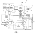
- FIG. 1 illustrates a synchronous generator control system 100 including a synchronous generator 102 driven by a power plant or engine 104.
- the power plant 104 may be an aircraft gas turbine.
- the synchronous generator 102 output is rectified using an active rectifier 106 to provide power to a DC bus 108.
- the DC bus voltage error V err is the difference between the bus voltage V dc and the desired bus voltage V ref .
- the DC bus voltage error V err is utilized as an input into a PID controller 110.
- the PID controller 110 provides a desired output power value P out , which the synchronous generator 102 should produce to maintain the bus voltage.
- the desired output power value P out (or alternately the desired output torque value T out ) as well as the measured speed ⁇ are inputs into the flux optimization control 200 that will be described in greater detail below.
- the outputs of the flux optimization control 200 include desired stator current i qs , i ds and desired field current magnitude i fd . These outputs are sent to an inner loop current controller 112 as well as a field excitation controller 114.
- the inner loop current controller 112 provides switching laws for the active rectifier 106 causing the machine stator currents to track the desired currents.
- the field excitation controller 114 controls the exciter 116 to ensure the desired field current i fd is achieved in the field winding.
- the generator control system 100 may also include a variety of additional components and controls such as, but not limited to, an algebraic transform control 118 for conversion between the a-b-c frame and the q-d frame, some form of PWM scheme 120 such as space vector modulation, an energy storage 122 and an energy load 124. It is contemplated that the energy load 124 may encompass any or all of the electrical needs of an aircraft or other system. It would be understood that the overall scheme could be modified and adapted by one skilled in the art in light of the present disclosure. It is contemplated that the flux optimization control 200 could be implemented in a variety of varied layouts and control schemes.
- FIG. 2 illustrates the flux optimization control 200 in accordance with the present disclosure.
- the flux optimization control 200 begins by performing a first machine efficiency equation 202 which solves for efficiency as a function of the stator current magnitude is, the stator current angle ⁇ , and the field current magnitude i fd and outputs a fixed stator current magnitude
- a constraint equation 204 is then performed utilizing either the desired power or torque (Pout or Tout) as a constraint in the efficiency equation.
- a first parametric optimization 206 is then executed assuming a fixed stator current magnitude
- a second parametric optimization 208 is executed assuming a fixed stator current magnitude
- the calculated desired field current magnitude i fd is looped back to the first parametric optimization 206 for use as the fixed field current magnitude
- the calculated desired field current magnitude i fd along with the desired stator current angle ⁇ are passed to an algebraic machine equation 210 where they are used to calculated a desired stator current magnitude i s .
- the desired stator current magnitude is is looped back to the first parametric optimization 206 for use as the fixed stator current magnitude
- an algebraic loop breaking step 212 positioned after the first parametric optimization 206.
- the algebraic loop breaking step 212 is contemplated to embody any mathematical arrangement that will act to resolve the loop quickly.
- the algebraic loop breaking step may comprise a stable low-pass filter.
- the algebraic loop breaking step 212 produces a filtered desired stator current angle ⁇ filtered .
- the control 200 may also include a second efficiency equations step 214 prior to the second parametric optimization 208.
- the second efficiency equation 214 solves efficiency in terms of stator current magnitude
- the second efficiency equation 214 within the looped arrangement, further improves the flux optimization response time.
- the looped portions of the control 200 continually produces a desired stator current magnitude
- the desired stator current magnitude is and the desired stator current angle ⁇ are utilized in calculation step 216 to calculate a stator i qs and i ds values which along with the desired field current magnitude i fd are continually output in an output step 218 to the inner loop current controller 112 as well as the field excitation controller 114.
- the dual looped optimization ensures that the voltage quickly reaches and maintains proper bus voltage while minimizing the copper resistive losses of the synchronous generator 102. It will be understood that one skilled in the art would recognize a variety of alterations or modifications in light of the present disclosure.
- a control method for a synchronous generator system comprising the steps of: performing a first parametric optimization to determine a desired stator current angle ⁇ assuming fixed stator current magnitude
- a synchronous generator control system comprising: a synchronous generator; an active rectifier in communication with the synchronous generator; an exciter current control in communication with the synchronous generator; and a flux optimizer controller in communication with the excited current control, the flux optimizer controller configured to: perform a first parametric optimization to determine a desired stator current angle ⁇ assuming fixed stator current magnitude
- a control method for a synchronous generator system comprising the steps of: performing a first machine efficiency equation prior to said first parametric optimization to determine a fixed stator current magnitude, a fixed stator current angle and a fixed field current magnitude; performing a constraint equation; performing a first parametric optimization to determine a desired stator current angle assuming said fixed stator current magnitude and said fixed field current magnitude; performing a second parametric optimization to determine a desired field current magnitude assuming said fixed stator current magnitude and a fixed stator current angle; calculating a desired stator current magnitude using said desired stator current angle and said desired field current magnitude; looping said first parametric optimization and said second parametric optimization; outputting said desired stator current magnitude, said desired stator current angle and said desired field current magnitude.
- the first parametric optimization and the second parametric optimization may be in a looped arrangement.
- the control method may further comprise: performing a first machine efficiency equation prior to the first parametric optimization to determine the fixed stator current magnitude
- the constraint equation may determine a desired output power value P out .
- the constraint equation may determine a desired output torque value T out .
- the control method may further comprise: performing a second machine efficiency equation using the desired stator current magnitude is and the desired stator current angle ⁇ to verify the first machine efficiency equation.
- the control method may further comprise: performing an algebraic loop breaking step to resolve the first parametric optimization and optionally the second parametric optimization.
- the algebraic loop breaking step may comprise a low-pass filter.
- the control method may further comprise: converting the desired stator current magnitude is and the desired stator current angle ⁇ to a q-axis current value and a d-axis current value.
- the flux optimizer controller may be further configured to: loop the first parametric optimization and the second parametric optimization.
- the flux optimizer controller may be further configured to: perform an algebraic loop breaking step to resolve the first parametric optimization and optionally the second parametric optimization.
- the synchronous generator control system may further comprise: a low-pass filter configured to perform the algebraic loop breaking step.
- the flux optimizer controller may be further configured to: perform a first machine efficiency equation prior to the first parametric optimization to determine the fixed stator current magnitude
- the flux optimizer controller may be further configured to: perform a second machine efficiency equation using the desired stator current magnitude is and the desired stator current angle ⁇ to verify the first machine efficiency equation.
Landscapes
- Engineering & Computer Science (AREA)
- Power Engineering (AREA)
- Transportation (AREA)
- Mechanical Engineering (AREA)
- Control Of Eletrric Generators (AREA)
Abstract
Description
- An improved an integrated design and control of a synchronous generator is disclosed. More particularly, a method for providing flux regulation while minimizing losses due to electrical impedance is disclosed.
- Synchronous generators are utilized in a variety of industries and for a variety of applications. Their use in propulsion systems such as in aircraft commonly comprises providing power for engine starting as well as electrical power generation for systems operations. The electrical power demands of aircraft, as well as other transportation modes, are continually increasing as industries move to greater electronic control.
- Traditional synchronous generators have a generator output that is controlled mainly by excitation voltage control. Traditional excitation voltage control may result in poor regulation of voltage and power factor in the presence of varying frequency and voltage. Modern operations require a well-regulated power converter irrespective of load variations, speed variations and operating conditions. Traditional excitation voltage control is not well suited to handle such variations. Additionally, the use of a fully controlled rectifier allows the controller to manipulate the vector of stator currents independently, as opposed to using passive rectification. The application of this vector control allows for finer tuning of the magnetic field, in such a way that can provide efficiency benefits.
- Overcoming these concerns would be desirable, could improve generator efficiency, and could minimize the amount of losses due to electrical impedance.
- According to the present disclosure, there is provided a control method for a synchronous generator system and a synchronous generator control system, as set forth in the appended claims.
- While the claims are not limited to a specific illustration, an appreciation of the various aspects is best gained through a discussion of various examples thereof. Referring now to the drawings, exemplary illustrations are shown in detail. Although the drawings represent the illustrations, the drawings are not necessarily to scale and certain features may be exaggerated to better illustrate and explain an innovative aspect of an example. Further, the exemplary illustrations described herein are not intended to be exhaustive or otherwise limiting or restricted to the precise form and configuration shown in the drawings and disclosed in the following detailed description. Exemplary illustrations are described in detail by referring to the drawings as follows:
-
FIG. 1 is a schematic illustration of a synchronous generator control system, according to one example; and -
FIG. 2 is an illustration of a flux optimization control for use with the synchronous generator control system illustrated inFIG. 1 . - An exemplary synchronous generator control system is described herein and is shown in the attached drawings. As aircraft design moves towards increasing quantity of electrical components and the resulting increase in electrical load, a system that can meet these high power demands while responding quickly to power generation needs is necessary. The present disclosure describes such a system. In addition, the present disclosure describes a method of regulating power in the presence of load variations, speed variations, and varied operating conditions. The synchronous generator control system controls flux levels used within field orientation control to minimize machine losses.
-
Figure 1 illustrates a synchronousgenerator control system 100 including asynchronous generator 102 driven by a power plant orengine 104. Thepower plant 104 may be an aircraft gas turbine. Thesynchronous generator 102 output is rectified using anactive rectifier 106 to provide power to a DC bus 108. The DC bus voltage error Verr is the difference between the bus voltage Vdc and the desired bus voltage Vref. The DC bus voltage error Verr is utilized as an input into aPID controller 110. ThePID controller 110 provides a desired output power value Pout, which thesynchronous generator 102 should produce to maintain the bus voltage. The desired output power value Pout (or alternately the desired output torque value Tout) as well as the measured speed ω are inputs into theflux optimization control 200 that will be described in greater detail below. The outputs of theflux optimization control 200 include desired stator current iqs, ids and desired field current magnitude ifd. These outputs are sent to an inner loopcurrent controller 112 as well as afield excitation controller 114. The inner loopcurrent controller 112 provides switching laws for theactive rectifier 106 causing the machine stator currents to track the desired currents. Thefield excitation controller 114 controls theexciter 116 to ensure the desired field current ifd is achieved in the field winding. - The
generator control system 100 may also include a variety of additional components and controls such as, but not limited to, analgebraic transform control 118 for conversion between the a-b-c frame and the q-d frame, some form ofPWM scheme 120 such as space vector modulation, anenergy storage 122 and anenergy load 124. It is contemplated that theenergy load 124 may encompass any or all of the electrical needs of an aircraft or other system. It would be understood that the overall scheme could be modified and adapted by one skilled in the art in light of the present disclosure. It is contemplated that theflux optimization control 200 could be implemented in a variety of varied layouts and control schemes. -
Figure 2 illustrates theflux optimization control 200 in accordance with the present disclosure. Theflux optimization control 200 begins by performing a firstmachine efficiency equation 202 which solves for efficiency as a function of the stator current magnitude is, the stator current angle α, and the field current magnitude ifd and outputs a fixed stator current magnitude |is|. a fixed stator current angle |α| and a fixed field current magnitude |ifd|. Aconstraint equation 204 is then performed utilizing either the desired power or torque (Pout or Tout) as a constraint in the efficiency equation. A firstparametric optimization 206 is then executed assuming a fixed stator current magnitude |is| and a fixed field current magnitude |ifd| in order to calculate a desired stator current angle α for efficiency. A secondparametric optimization 208 is executed assuming a fixed stator current magnitude |is| and a fixed stator current angle |α| in order to calculate a desired field current magnitude ifd. The calculated desired field current magnitude ifd is looped back to the firstparametric optimization 206 for use as the fixed field current magnitude |ifd|. In addition, the calculated desired field current magnitude ifd along with the desired stator current angle α are passed to analgebraic machine equation 210 where they are used to calculated a desired stator current magnitude is. The desired stator current magnitude is is looped back to the firstparametric optimization 206 for use as the fixed stator current magnitude |is|. In this fashion, the firstparametric optimization 206 and the secondparametric optimization 208 operate in a looped arrangement. - In order to resolve this algebraic loop, the disclosure contemplates the use of an algebraic
loop breaking step 212 positioned after the firstparametric optimization 206. The algebraicloop breaking step 212 is contemplated to embody any mathematical arrangement that will act to resolve the loop quickly. The algebraic loop breaking step may comprise a stable low-pass filter. The algebraicloop breaking step 212 produces a filtered desired stator current angle αfiltered. In addition, thecontrol 200 may also include a secondefficiency equations step 214 prior to the secondparametric optimization 208. Thesecond efficiency equation 214 solves efficiency in terms of stator current magnitude |is| and stator current angle α. Thesecond efficiency equation 214, within the looped arrangement, further improves the flux optimization response time. - The looped portions of the
control 200 continually produces a desired stator current magnitude |is|, a desired stator current angle α, and a desired field current magnitude ifd. The desired stator current magnitude is and the desired stator current angle α are utilized incalculation step 216 to calculate a stator iqs and ids values which along with the desired field current magnitude ifd are continually output in anoutput step 218 to the inner loopcurrent controller 112 as well as thefield excitation controller 114. The dual looped optimization ensures that the voltage quickly reaches and maintains proper bus voltage while minimizing the copper resistive losses of thesynchronous generator 102. It will be understood that one skilled in the art would recognize a variety of alterations or modifications in light of the present disclosure. - According to a first aspect, there is provided a control method for a synchronous generator system comprising the steps of: performing a first parametric optimization to determine a desired stator current angle α assuming fixed stator current magnitude |is| and fixed field current magnitude |ifd|; performing a second parametric optimization to determine a desired field current magnitude ifd assuming fixed stator current magnitude |is| and fixed stator current angle |α|; calculating a desired stator current magnitude is using the desired stator current angle α and the desired field current magnitude ifd; and outputting the desired stator current magnitude is, the desired stator current angle α and the desired field current magnitude ifd.
- According to a second aspect, there is provided a synchronous generator control system comprising: a synchronous generator; an active rectifier in communication with the synchronous generator; an exciter current control in communication with the synchronous generator; and a flux optimizer controller in communication with the excited current control, the flux optimizer controller configured to: perform a first parametric optimization to determine a desired stator current angle α assuming fixed stator current magnitude |is| and fixed field current magnitude |ifd|; perform a second parametric optimization to determine a desired field current magnitude ifd assuming fixed stator current magnitude |is| and fixed stator current angle |α|; calculate a desired stator current magnitude is using the desired stator current angle α and the desired field current magnitude ifd; and output the desired stator current magnitude is, the desired stator current angle α and the desired field current magnitude ifd.
- According to a further aspect, there is provided a control method for a synchronous generator system comprising the steps of: performing a first machine efficiency equation prior to said first parametric optimization to determine a fixed stator current magnitude, a fixed stator current angle and a fixed field current magnitude; performing a constraint equation; performing a first parametric optimization to determine a desired stator current angle assuming said fixed stator current magnitude and said fixed field current magnitude; performing a second parametric optimization to determine a desired field current magnitude assuming said fixed stator current magnitude and a fixed stator current angle; calculating a desired stator current magnitude using said desired stator current angle and said desired field current magnitude; looping said first parametric optimization and said second parametric optimization; outputting said desired stator current magnitude, said desired stator current angle and said desired field current magnitude.
- The first parametric optimization and the second parametric optimization may be in a looped arrangement.
- The control method may further comprise: performing a first machine efficiency equation prior to the first parametric optimization to determine the fixed stator current magnitude |is|, the fixed stator current angle |α| and the fixed field current magnitude |ifd|; and performing a constraint equation.
- The constraint equation may determine a desired output power value Pout.
- The constraint equation may determine a desired output torque value Tout.
- The control method may further comprise: performing a second machine efficiency equation using the desired stator current magnitude is and the desired stator current angle α to verify the first machine efficiency equation.
- The control method may further comprise: performing an algebraic loop breaking step to resolve the first parametric optimization and optionally the second parametric optimization.
- The algebraic loop breaking step may comprise a low-pass filter.
- The control method may further comprise: converting the desired stator current magnitude is and the desired stator current angle α to a q-axis current value and a d-axis current value.
- The flux optimizer controller may be further configured to: loop the first parametric optimization and the second parametric optimization.
- The flux optimizer controller may be further configured to: perform an algebraic loop breaking step to resolve the first parametric optimization and optionally the second parametric optimization.
- The synchronous generator control system may further comprise: a low-pass filter configured to perform the algebraic loop breaking step.
- The flux optimizer controller may be further configured to: perform a first machine efficiency equation prior to the first parametric optimization to determine the fixed stator current magnitude |is|, the fixed stator current angle |α| and the fixed field current magnitude |ifd|; and perform a constraint equation.
- The flux optimizer controller may be further configured to: perform a second machine efficiency equation using the desired stator current magnitude is and the desired stator current angle α to verify the first machine efficiency equation.
- It will be appreciated that the aforementioned method and devices may be modified to have some components and steps removed, or may have additional components and steps added, all of which are deemed to be within the spirit of the present disclosure. Even though the present disclosure has been described in detail with reference to specific embodiments, it will be appreciated that the various modifications and changes can be made to these embodiments without departing from the scope of the present disclosure as set forth in the claims. The specification and the drawings are to be regarded as an illustrative thought instead of merely restrictive thought.
Claims (15)
- A control method for a synchronous generator system (100) comprising the steps of:performing a first parametric optimization (206) to determine a desired stator current angle (α) assuming fixed stator current magnitude (|is|) and fixed field current magnitude (|ifd|);performing a second parametric optimization (208) to determine a desired field current magnitude (ifd) assuming fixed stator current magnitude (|is|) and fixed stator current angle (|α|);calculating a desired stator current magnitude (is) using the desired stator current angle (α) and the desired field current magnitude (ifd); andoutputting the desired stator current magnitude (is), the desired stator current angle (α) and the desired field current magnitude (ifd).
- A control method for a synchronous generator system (100) as claimed in claim 1, wherein the first parametric optimization (206) and the second parametric optimization (208) are in a looped arrangement.
- A control method for a synchronous generator system (100) as claimed in claims 1 or 2, further comprising:performing a first machine efficiency equation (202) prior to the first parametric optimization (206) to determine the fixed stator current magnitude (|is|), the fixed stator current angle (|α|) and the fixed field current magnitude (|ifd|); andperforming a constraint equation (204).
- A control method for a synchronous generator system (100) as claimed in claim 3, wherein the constraint equation (204) determines a desired output power value (Pout).
- A control method for a synchronous generator system (100) as claimed in claim 3, wherein the constraint equation (204) determines a desired output torque value (Tout).
- A control method for a synchronous generator system (100) as claimed in any one of claims 3, 4 or 5, further comprising:performing a second machine efficiency equation (214) using the desired stator current magnitude (is) and the desired stator current angle (α) to verify the first machine efficiency equation (202).
- A control method for a synchronous generator system (100) as claimed in any of the preceding claims, further comprising:performing an algebraic loop breaking step (212) to resolve the first parametric optimization (206) and optionally the second parametric optimization (208).
- A control method for a synchronous generator system (100) as claimed in claim 6, wherein the algebraic loop breaking step (212) comprises a low-pass filter.
- A control method for a synchronous generator system (100) as claimed in any of the preceding claims, further comprising:converting the desired stator current magnitude (is) and the desired stator current angle (α) to a q-axis current value and a d-axis current value.
- A synchronous generator control system (100) comprising:a synchronous generator (102);an active rectifier (106) in communication with the synchronous generator (102);an exciter current control in communication with the synchronous generator (102); anda flux optimizer controller (200) in communication with the excited current control, the flux optimizer controller (200) configured to:perform a first parametric optimization (206) to determine a desired stator current angle (α) assuming fixed stator current magnitude (|is|) and fixed field current magnitude (|ifd|);perform a second parametric optimization (208) to determine a desired field current magnitude (ifd) assuming fixed stator current magnitude (|is|) and fixed stator current angle (|α|);calculate a desired stator current magnitude (is) using the desired stator current angle (α) and the desired field current magnitude (ifd); andoutput the desired stator current magnitude (is), the desired stator current angle (α) and the desired field current magnitude (ifd).
- A synchronous generator control system (100) as claimed in claim 10, wherein the flux optimizer controller (200) is further configured to:loop the first parametric optimization (206) and the second parametric optimization (208).
- A synchronous generator control system (100) as claimed in any one of claims 10 or 11, wherein the flux optimizer controller (200) is further configured to:perform an algebraic loop breaking step (212) to resolve the first parametric optimization (206) and optionally the second parametric optimization (208).
- A synchronous generator control system (100) as claimed in claim 12, further comprising:a low-pass filter configured to perform the algebraic loop breaking step (212).
- A synchronous generator control system (100) as claimed in any one of claims 10 to 13, wherein the flux optimizer controller (200) is further configured to:perform a first machine efficiency equation (202) prior to the first parametric optimization (206) to determine the fixed stator current magnitude (|is|), the fixed stator current angle (|α|) and the fixed field current magnitude (|ifd|); andperform a constraint equation (204).
- A synchronous generator control system as claimed in claim 18, wherein the flux optimizer controller is further configured to:perform a second machine efficiency equation (214) using the desired stator current magnitude (is) and the desired stator current angle (α) to verify the first machine efficiency equation (202).
Applications Claiming Priority (1)
| Application Number | Priority Date | Filing Date | Title |
|---|---|---|---|
| US201361921974P | 2013-12-30 | 2013-12-30 |
Publications (2)
| Publication Number | Publication Date |
|---|---|
| EP2889178A1 true EP2889178A1 (en) | 2015-07-01 |
| EP2889178B1 EP2889178B1 (en) | 2020-06-24 |
Family
ID=52144599
Family Applications (1)
| Application Number | Title | Priority Date | Filing Date |
|---|---|---|---|
| EP14200485.2A Active EP2889178B1 (en) | 2013-12-30 | 2014-12-29 | Synchronous generator control based on flux optimizer |
Country Status (2)
| Country | Link |
|---|---|
| US (1) | US20150249417A1 (en) |
| EP (1) | EP2889178B1 (en) |
Cited By (3)
| Publication number | Priority date | Publication date | Assignee | Title |
|---|---|---|---|---|
| CN107425767A (en) * | 2017-07-31 | 2017-12-01 | 上海交通大学 | Wind electric converter failure reconfiguration optimal control method is pressed in cascaded H-bridges |
| CN108566129B (en) * | 2018-05-31 | 2021-06-22 | 南京航空航天大学 | Permanent magnet power generation system for reducing voltage fluctuation on direct current side and control method thereof |
| EP4102715A1 (en) | 2021-06-08 | 2022-12-14 | Rolls-Royce plc | Permanent magnet electric machine control |
Families Citing this family (3)
| Publication number | Priority date | Publication date | Assignee | Title |
|---|---|---|---|---|
| EP3537597B1 (en) * | 2016-11-02 | 2020-09-30 | Mitsubishi Electric Corporation | Control device for electric generator/motor and control method for electric generator/motor |
| US11218145B2 (en) * | 2017-08-30 | 2022-01-04 | University Of Houston System | High temperature gate driver for silicon carbide metal-oxide-semiconductor field-effect transistor |
| CN117155183B (en) * | 2023-09-01 | 2024-04-09 | 无锡法拉第电机有限公司 | Synchronous generator excitation control system and method based on optimization algorithm |
Citations (5)
| Publication number | Priority date | Publication date | Assignee | Title |
|---|---|---|---|---|
| US6359421B1 (en) * | 1998-10-29 | 2002-03-19 | Robert Bosch Gmbh | Method for the optimized control in terms of output and efficiency of synchronous machines |
| FR2948512A1 (en) * | 2009-07-24 | 2011-01-28 | Peugeot Citroen Automobiles Sa | Power supply device controlling method for e.g. motor vehicle, involves determining set point value of alternator excitation command according to rotation speed of rotor of alternator and electric power consumed by load |
| US8242720B2 (en) * | 2008-09-23 | 2012-08-14 | Aerovironment, Inc. | Sensorless optimum torque control for high efficiency ironless permanent magnet machine |
| US20130027002A1 (en) * | 2011-07-25 | 2013-01-31 | Kaushik Rajashekara | Systems and methods for synchronous power generation |
| WO2013060996A1 (en) * | 2011-10-28 | 2013-05-02 | Valeo Equipements Electriques Moteur | Method for controlling a double excitation synchronous rotating electric machine and corresponding rotating electric machine |
Family Cites Families (13)
| Publication number | Priority date | Publication date | Assignee | Title |
|---|---|---|---|---|
| US5168208A (en) * | 1988-05-09 | 1992-12-01 | Onan Corporation | Microprocessor based integrated generator set controller apparatus and method |
| US5418446A (en) * | 1993-05-10 | 1995-05-23 | Hallidy; William M. | Variable speed constant frequency synchronous electric power generating system and method of using same |
| US6069467A (en) * | 1998-11-16 | 2000-05-30 | General Electric Company | Sensorless rotor tracking of induction machines with asymmetrical rotor resistance |
| US6281664B1 (en) * | 1999-01-13 | 2001-08-28 | Honda Giken Kogyo Kabushiki Kaisha | Generator and generator apparatus |
| DE10336068B4 (en) * | 2003-08-06 | 2006-04-06 | Siemens Ag | Method for the controlled imprinting of a stator current and a torque setpoint for a converter-fed induction machine |
| US7215100B2 (en) * | 2005-03-21 | 2007-05-08 | Teleflex Canada Inc. | Generator transient regulator |
| US7307403B2 (en) * | 2005-11-08 | 2007-12-11 | Honeywell International, Inc. | System and method for DC power generation from a reluctance machine |
| US8080980B2 (en) * | 2009-03-11 | 2011-12-20 | Remy Technologies, L.L.C. | Alternator regulator with automatic regulation dependent on system voltage |
| ES2669026T3 (en) * | 2009-09-18 | 2018-05-23 | Vestas Wind Systems A/S | A method for controlling a wind turbine generator and apparatus for controlling the electrical power generated by a wind turbine generator |
| EP2599215B1 (en) * | 2010-07-28 | 2021-05-19 | Vitesco Technologies GmbH | Method and device for regulating separately excited synchronous machines |
| FR2971377B1 (en) * | 2011-02-09 | 2013-02-01 | Renault Sa | METHOD AND DEVICE FOR CONTROLLING A RELUCTANCE ELECTRIC MACHINE |
| FR2971648B1 (en) * | 2011-02-16 | 2016-10-14 | Moteurs Leroy-Somer | VARIABLE-RATE OPERATING ASSEMBLY HAVING SYNCHRONOUS ROTOR-ROLLER ALTERNATOR AND CONVERTER |
| US8975876B2 (en) * | 2013-03-15 | 2015-03-10 | Hamilton Sunstrand Corporation | Method of controlling rotating main field converter |
-
2014
- 2014-12-22 US US14/579,198 patent/US20150249417A1/en not_active Abandoned
- 2014-12-29 EP EP14200485.2A patent/EP2889178B1/en active Active
Patent Citations (5)
| Publication number | Priority date | Publication date | Assignee | Title |
|---|---|---|---|---|
| US6359421B1 (en) * | 1998-10-29 | 2002-03-19 | Robert Bosch Gmbh | Method for the optimized control in terms of output and efficiency of synchronous machines |
| US8242720B2 (en) * | 2008-09-23 | 2012-08-14 | Aerovironment, Inc. | Sensorless optimum torque control for high efficiency ironless permanent magnet machine |
| FR2948512A1 (en) * | 2009-07-24 | 2011-01-28 | Peugeot Citroen Automobiles Sa | Power supply device controlling method for e.g. motor vehicle, involves determining set point value of alternator excitation command according to rotation speed of rotor of alternator and electric power consumed by load |
| US20130027002A1 (en) * | 2011-07-25 | 2013-01-31 | Kaushik Rajashekara | Systems and methods for synchronous power generation |
| WO2013060996A1 (en) * | 2011-10-28 | 2013-05-02 | Valeo Equipements Electriques Moteur | Method for controlling a double excitation synchronous rotating electric machine and corresponding rotating electric machine |
Cited By (4)
| Publication number | Priority date | Publication date | Assignee | Title |
|---|---|---|---|---|
| CN107425767A (en) * | 2017-07-31 | 2017-12-01 | 上海交通大学 | Wind electric converter failure reconfiguration optimal control method is pressed in cascaded H-bridges |
| CN108566129B (en) * | 2018-05-31 | 2021-06-22 | 南京航空航天大学 | Permanent magnet power generation system for reducing voltage fluctuation on direct current side and control method thereof |
| EP4102715A1 (en) | 2021-06-08 | 2022-12-14 | Rolls-Royce plc | Permanent magnet electric machine control |
| US11881796B2 (en) | 2021-06-08 | 2024-01-23 | Rolls Royce Plc | Permanent magnet electric machine control |
Also Published As
| Publication number | Publication date |
|---|---|
| US20150249417A1 (en) | 2015-09-03 |
| EP2889178B1 (en) | 2020-06-24 |
Similar Documents
| Publication | Publication Date | Title |
|---|---|---|
| US9998058B2 (en) | Control apparatus for AC motor | |
| EP2889178A1 (en) | Synchronous generator control based on flux optimizer | |
| Bozhko et al. | Aircraft starter-generator system based on permanent-magnet machine fed by active front-end rectifier | |
| EP2865889B1 (en) | Damping of wind turbine drive train oscillations | |
| US9429136B2 (en) | Control system of variable speed pumped storage hydropower system and method of controlling the same | |
| KR20170015963A (en) | Method and device for optimizing efficiency of induction motor in electric vehicle | |
| JP2009516488A (en) | Power converter | |
| CN102150356A (en) | Direct power control with component separation | |
| JP2014003783A (en) | Power converter controller and multiplex winding-type motor drive unit | |
| US10833605B2 (en) | Space vector modulation in aerospace applications | |
| CN111066237A (en) | Method for controlling a polyphase separately excited synchronous generator for a wind energy facility | |
| Bu et al. | An integrated AC and DC hybrid generation system using dual-stator-winding induction generator with static excitation controller | |
| CN109546913A (en) | A kind of capacitor miniaturization motor driver | |
| JPWO2016017304A1 (en) | Power converter | |
| CN103259476B (en) | Frequency conversion alternating current generation system control method with voltage harmonic suppression function | |
| Banerjee et al. | Control architecture for a switched doubly fed machine propulsion drive | |
| Wu et al. | Angle position compensation control strategy for high-speed power generation of aerospace integrated switched reluctance starting/generating system | |
| CN107923368B (en) | Method of adjusting a wind turbine power take off | |
| JP6207427B2 (en) | Method for determining preferred rotational speed, control method for power generation system, and power generation system using the control method | |
| Rabiaa et al. | Scalar speed control of dual three phase induction motor using PI and IP controllers | |
| KR20210019058A (en) | Thyristor starting device | |
| JP2014003746A (en) | Control device for drive system | |
| Howlader et al. | Optimal PAM control for a buck boost DC-DC converter with a wide-speed-range of operation for a PMSM | |
| Junejo et al. | Advanced Sliding Mode Control for Electric Machines and Drive Systems | |
| Bozhko et al. | Control design for electric starter-generator based on a high-speed permanent-magnet machine fed by an active front-end rectifier |
Legal Events
| Date | Code | Title | Description |
|---|---|---|---|
| PUAI | Public reference made under article 153(3) epc to a published international application that has entered the european phase |
Free format text: ORIGINAL CODE: 0009012 |
|
| 17P | Request for examination filed |
Effective date: 20141229 |
|
| AK | Designated contracting states |
Kind code of ref document: A1 Designated state(s): AL AT BE BG CH CY CZ DE DK EE ES FI FR GB GR HR HU IE IS IT LI LT LU LV MC MK MT NL NO PL PT RO RS SE SI SK SM TR |
|
| AX | Request for extension of the european patent |
Extension state: BA ME |
|
| R17P | Request for examination filed (corrected) |
Effective date: 20151230 |
|
| RBV | Designated contracting states (corrected) |
Designated state(s): AL AT BE BG CH CY CZ DE DK EE ES FI FR GB GR HR HU IE IS IT LI LT LU LV MC MK MT NL NO PL PT RO RS SE SI SK SM TR |
|
| STAA | Information on the status of an ep patent application or granted ep patent |
Free format text: STATUS: EXAMINATION IS IN PROGRESS |
|
| 17Q | First examination report despatched |
Effective date: 20190617 |
|
| GRAP | Despatch of communication of intention to grant a patent |
Free format text: ORIGINAL CODE: EPIDOSNIGR1 |
|
| STAA | Information on the status of an ep patent application or granted ep patent |
Free format text: STATUS: GRANT OF PATENT IS INTENDED |
|
| RIC1 | Information provided on ipc code assigned before grant |
Ipc: H02P 9/48 20060101ALI20200128BHEP Ipc: H02P 21/00 20160101ALI20200128BHEP Ipc: H02P 21/22 20160101ALI20200128BHEP Ipc: H02P 9/10 20060101ALI20200128BHEP Ipc: H02P 31/00 20060101ALI20200128BHEP Ipc: B60L 15/20 20060101ALI20200128BHEP Ipc: B60L 15/02 20060101AFI20200128BHEP |
|
| INTG | Intention to grant announced |
Effective date: 20200214 |
|
| GRAS | Grant fee paid |
Free format text: ORIGINAL CODE: EPIDOSNIGR3 |
|
| GRAA | (expected) grant |
Free format text: ORIGINAL CODE: 0009210 |
|
| STAA | Information on the status of an ep patent application or granted ep patent |
Free format text: STATUS: THE PATENT HAS BEEN GRANTED |
|
| AK | Designated contracting states |
Kind code of ref document: B1 Designated state(s): AL AT BE BG CH CY CZ DE DK EE ES FI FR GB GR HR HU IE IS IT LI LT LU LV MC MK MT NL NO PL PT RO RS SE SI SK SM TR |
|
| REG | Reference to a national code |
Ref country code: GB Ref legal event code: FG4D |
|
| REG | Reference to a national code |
Ref country code: CH Ref legal event code: EP |
|
| REG | Reference to a national code |
Ref country code: DE Ref legal event code: R096 Ref document number: 602014066938 Country of ref document: DE |
|
| REG | Reference to a national code |
Ref country code: AT Ref legal event code: REF Ref document number: 1283553 Country of ref document: AT Kind code of ref document: T Effective date: 20200715 |
|
| REG | Reference to a national code |
Ref country code: IE Ref legal event code: FG4D |
|
| PG25 | Lapsed in a contracting state [announced via postgrant information from national office to epo] |
Ref country code: LT Free format text: LAPSE BECAUSE OF FAILURE TO SUBMIT A TRANSLATION OF THE DESCRIPTION OR TO PAY THE FEE WITHIN THE PRESCRIBED TIME-LIMIT Effective date: 20200624 Ref country code: GR Free format text: LAPSE BECAUSE OF FAILURE TO SUBMIT A TRANSLATION OF THE DESCRIPTION OR TO PAY THE FEE WITHIN THE PRESCRIBED TIME-LIMIT Effective date: 20200925 Ref country code: FI Free format text: LAPSE BECAUSE OF FAILURE TO SUBMIT A TRANSLATION OF THE DESCRIPTION OR TO PAY THE FEE WITHIN THE PRESCRIBED TIME-LIMIT Effective date: 20200624 Ref country code: NO Free format text: LAPSE BECAUSE OF FAILURE TO SUBMIT A TRANSLATION OF THE DESCRIPTION OR TO PAY THE FEE WITHIN THE PRESCRIBED TIME-LIMIT Effective date: 20200924 Ref country code: SE Free format text: LAPSE BECAUSE OF FAILURE TO SUBMIT A TRANSLATION OF THE DESCRIPTION OR TO PAY THE FEE WITHIN THE PRESCRIBED TIME-LIMIT Effective date: 20200624 |
|
| REG | Reference to a national code |
Ref country code: LT Ref legal event code: MG4D |
|
| PG25 | Lapsed in a contracting state [announced via postgrant information from national office to epo] |
Ref country code: BG Free format text: LAPSE BECAUSE OF FAILURE TO SUBMIT A TRANSLATION OF THE DESCRIPTION OR TO PAY THE FEE WITHIN THE PRESCRIBED TIME-LIMIT Effective date: 20200924 Ref country code: LV Free format text: LAPSE BECAUSE OF FAILURE TO SUBMIT A TRANSLATION OF THE DESCRIPTION OR TO PAY THE FEE WITHIN THE PRESCRIBED TIME-LIMIT Effective date: 20200624 Ref country code: RS Free format text: LAPSE BECAUSE OF FAILURE TO SUBMIT A TRANSLATION OF THE DESCRIPTION OR TO PAY THE FEE WITHIN THE PRESCRIBED TIME-LIMIT Effective date: 20200624 Ref country code: HR Free format text: LAPSE BECAUSE OF FAILURE TO SUBMIT A TRANSLATION OF THE DESCRIPTION OR TO PAY THE FEE WITHIN THE PRESCRIBED TIME-LIMIT Effective date: 20200624 |
|
| REG | Reference to a national code |
Ref country code: NL Ref legal event code: MP Effective date: 20200624 |
|
| REG | Reference to a national code |
Ref country code: AT Ref legal event code: MK05 Ref document number: 1283553 Country of ref document: AT Kind code of ref document: T Effective date: 20200624 |
|
| PG25 | Lapsed in a contracting state [announced via postgrant information from national office to epo] |
Ref country code: NL Free format text: LAPSE BECAUSE OF FAILURE TO SUBMIT A TRANSLATION OF THE DESCRIPTION OR TO PAY THE FEE WITHIN THE PRESCRIBED TIME-LIMIT Effective date: 20200624 Ref country code: AL Free format text: LAPSE BECAUSE OF FAILURE TO SUBMIT A TRANSLATION OF THE DESCRIPTION OR TO PAY THE FEE WITHIN THE PRESCRIBED TIME-LIMIT Effective date: 20200624 |
|
| PG25 | Lapsed in a contracting state [announced via postgrant information from national office to epo] |
Ref country code: EE Free format text: LAPSE BECAUSE OF FAILURE TO SUBMIT A TRANSLATION OF THE DESCRIPTION OR TO PAY THE FEE WITHIN THE PRESCRIBED TIME-LIMIT Effective date: 20200624 Ref country code: SM Free format text: LAPSE BECAUSE OF FAILURE TO SUBMIT A TRANSLATION OF THE DESCRIPTION OR TO PAY THE FEE WITHIN THE PRESCRIBED TIME-LIMIT Effective date: 20200624 Ref country code: RO Free format text: LAPSE BECAUSE OF FAILURE TO SUBMIT A TRANSLATION OF THE DESCRIPTION OR TO PAY THE FEE WITHIN THE PRESCRIBED TIME-LIMIT Effective date: 20200624 Ref country code: IT Free format text: LAPSE BECAUSE OF FAILURE TO SUBMIT A TRANSLATION OF THE DESCRIPTION OR TO PAY THE FEE WITHIN THE PRESCRIBED TIME-LIMIT Effective date: 20200624 Ref country code: AT Free format text: LAPSE BECAUSE OF FAILURE TO SUBMIT A TRANSLATION OF THE DESCRIPTION OR TO PAY THE FEE WITHIN THE PRESCRIBED TIME-LIMIT Effective date: 20200624 Ref country code: CZ Free format text: LAPSE BECAUSE OF FAILURE TO SUBMIT A TRANSLATION OF THE DESCRIPTION OR TO PAY THE FEE WITHIN THE PRESCRIBED TIME-LIMIT Effective date: 20200624 Ref country code: ES Free format text: LAPSE BECAUSE OF FAILURE TO SUBMIT A TRANSLATION OF THE DESCRIPTION OR TO PAY THE FEE WITHIN THE PRESCRIBED TIME-LIMIT Effective date: 20200624 Ref country code: PT Free format text: LAPSE BECAUSE OF FAILURE TO SUBMIT A TRANSLATION OF THE DESCRIPTION OR TO PAY THE FEE WITHIN THE PRESCRIBED TIME-LIMIT Effective date: 20201026 |
|
| PG25 | Lapsed in a contracting state [announced via postgrant information from national office to epo] |
Ref country code: IS Free format text: LAPSE BECAUSE OF FAILURE TO SUBMIT A TRANSLATION OF THE DESCRIPTION OR TO PAY THE FEE WITHIN THE PRESCRIBED TIME-LIMIT Effective date: 20201024 Ref country code: SK Free format text: LAPSE BECAUSE OF FAILURE TO SUBMIT A TRANSLATION OF THE DESCRIPTION OR TO PAY THE FEE WITHIN THE PRESCRIBED TIME-LIMIT Effective date: 20200624 Ref country code: PL Free format text: LAPSE BECAUSE OF FAILURE TO SUBMIT A TRANSLATION OF THE DESCRIPTION OR TO PAY THE FEE WITHIN THE PRESCRIBED TIME-LIMIT Effective date: 20200624 |
|
| REG | Reference to a national code |
Ref country code: DE Ref legal event code: R097 Ref document number: 602014066938 Country of ref document: DE |
|
| PG25 | Lapsed in a contracting state [announced via postgrant information from national office to epo] |
Ref country code: DK Free format text: LAPSE BECAUSE OF FAILURE TO SUBMIT A TRANSLATION OF THE DESCRIPTION OR TO PAY THE FEE WITHIN THE PRESCRIBED TIME-LIMIT Effective date: 20200624 |
|
| PLBE | No opposition filed within time limit |
Free format text: ORIGINAL CODE: 0009261 |
|
| STAA | Information on the status of an ep patent application or granted ep patent |
Free format text: STATUS: NO OPPOSITION FILED WITHIN TIME LIMIT |
|
| 26N | No opposition filed |
Effective date: 20210325 |
|
| REG | Reference to a national code |
Ref country code: DE Ref legal event code: R119 Ref document number: 602014066938 Country of ref document: DE |
|
| REG | Reference to a national code |
Ref country code: CH Ref legal event code: PL |
|
| GBPC | Gb: european patent ceased through non-payment of renewal fee |
Effective date: 20201229 |
|
| PG25 | Lapsed in a contracting state [announced via postgrant information from national office to epo] |
Ref country code: SI Free format text: LAPSE BECAUSE OF FAILURE TO SUBMIT A TRANSLATION OF THE DESCRIPTION OR TO PAY THE FEE WITHIN THE PRESCRIBED TIME-LIMIT Effective date: 20200624 Ref country code: MC Free format text: LAPSE BECAUSE OF FAILURE TO SUBMIT A TRANSLATION OF THE DESCRIPTION OR TO PAY THE FEE WITHIN THE PRESCRIBED TIME-LIMIT Effective date: 20200624 |
|
| REG | Reference to a national code |
Ref country code: BE Ref legal event code: MM Effective date: 20201231 |
|
| PG25 | Lapsed in a contracting state [announced via postgrant information from national office to epo] |
Ref country code: IE Free format text: LAPSE BECAUSE OF NON-PAYMENT OF DUE FEES Effective date: 20201229 Ref country code: LU Free format text: LAPSE BECAUSE OF NON-PAYMENT OF DUE FEES Effective date: 20201229 |
|
| PG25 | Lapsed in a contracting state [announced via postgrant information from national office to epo] |
Ref country code: LI Free format text: LAPSE BECAUSE OF NON-PAYMENT OF DUE FEES Effective date: 20201231 Ref country code: CH Free format text: LAPSE BECAUSE OF NON-PAYMENT OF DUE FEES Effective date: 20201231 Ref country code: GB Free format text: LAPSE BECAUSE OF NON-PAYMENT OF DUE FEES Effective date: 20201229 Ref country code: DE Free format text: LAPSE BECAUSE OF NON-PAYMENT OF DUE FEES Effective date: 20210701 |
|
| PG25 | Lapsed in a contracting state [announced via postgrant information from national office to epo] |
Ref country code: IS Free format text: LAPSE BECAUSE OF FAILURE TO SUBMIT A TRANSLATION OF THE DESCRIPTION OR TO PAY THE FEE WITHIN THE PRESCRIBED TIME-LIMIT Effective date: 20201024 Ref country code: TR Free format text: LAPSE BECAUSE OF FAILURE TO SUBMIT A TRANSLATION OF THE DESCRIPTION OR TO PAY THE FEE WITHIN THE PRESCRIBED TIME-LIMIT Effective date: 20200624 Ref country code: MT Free format text: LAPSE BECAUSE OF FAILURE TO SUBMIT A TRANSLATION OF THE DESCRIPTION OR TO PAY THE FEE WITHIN THE PRESCRIBED TIME-LIMIT Effective date: 20200624 Ref country code: CY Free format text: LAPSE BECAUSE OF FAILURE TO SUBMIT A TRANSLATION OF THE DESCRIPTION OR TO PAY THE FEE WITHIN THE PRESCRIBED TIME-LIMIT Effective date: 20200624 |
|
| PG25 | Lapsed in a contracting state [announced via postgrant information from national office to epo] |
Ref country code: MK Free format text: LAPSE BECAUSE OF FAILURE TO SUBMIT A TRANSLATION OF THE DESCRIPTION OR TO PAY THE FEE WITHIN THE PRESCRIBED TIME-LIMIT Effective date: 20200624 |
|
| PG25 | Lapsed in a contracting state [announced via postgrant information from national office to epo] |
Ref country code: BE Free format text: LAPSE BECAUSE OF NON-PAYMENT OF DUE FEES Effective date: 20201231 |
|
| P01 | Opt-out of the competence of the unified patent court (upc) registered |
Effective date: 20230528 |
|
| PGFP | Annual fee paid to national office [announced via postgrant information from national office to epo] |
Ref country code: FR Payment date: 20251230 Year of fee payment: 12 |