EP2889145A2 - Recording apparatus - Google Patents
Recording apparatus Download PDFInfo
- Publication number
- EP2889145A2 EP2889145A2 EP14199836.9A EP14199836A EP2889145A2 EP 2889145 A2 EP2889145 A2 EP 2889145A2 EP 14199836 A EP14199836 A EP 14199836A EP 2889145 A2 EP2889145 A2 EP 2889145A2
- Authority
- EP
- European Patent Office
- Prior art keywords
- recording
- recording medium
- static eliminator
- recording apparatus
- section
- Prior art date
- Legal status (The legal status is an assumption and is not a legal conclusion. Google has not performed a legal analysis and makes no representation as to the accuracy of the status listed.)
- Granted
Links
- 230000003068 static effect Effects 0.000 claims abstract description 139
- 230000005611 electricity Effects 0.000 claims abstract description 26
- 239000000976 ink Substances 0.000 claims description 39
- 238000007599 discharging Methods 0.000 claims description 10
- 230000007613 environmental effect Effects 0.000 claims description 7
- 238000009434 installation Methods 0.000 claims description 7
- 230000032258 transport Effects 0.000 description 38
- 239000003595 mist Substances 0.000 description 19
- 238000011109 contamination Methods 0.000 description 12
- 230000007246 mechanism Effects 0.000 description 9
- 239000000428 dust Substances 0.000 description 8
- 230000007723 transport mechanism Effects 0.000 description 7
- 230000008030 elimination Effects 0.000 description 6
- 238000003379 elimination reaction Methods 0.000 description 6
- 238000004804 winding Methods 0.000 description 6
- 238000001035 drying Methods 0.000 description 4
- 230000003287 optical effect Effects 0.000 description 3
- 230000015572 biosynthetic process Effects 0.000 description 2
- 238000010586 diagram Methods 0.000 description 2
- 150000002500 ions Chemical class 0.000 description 2
- 238000011144 upstream manufacturing Methods 0.000 description 2
- 238000010438 heat treatment Methods 0.000 description 1
- 230000004048 modification Effects 0.000 description 1
- 238000012986 modification Methods 0.000 description 1
Images


Classifications
-
- B—PERFORMING OPERATIONS; TRANSPORTING
- B41—PRINTING; LINING MACHINES; TYPEWRITERS; STAMPS
- B41J—TYPEWRITERS; SELECTIVE PRINTING MECHANISMS, i.e. MECHANISMS PRINTING OTHERWISE THAN FROM A FORME; CORRECTION OF TYPOGRAPHICAL ERRORS
- B41J11/00—Devices or arrangements of selective printing mechanisms, e.g. ink-jet printers or thermal printers, for supporting or handling copy material in sheet or web form
- B41J11/0015—Devices or arrangements of selective printing mechanisms, e.g. ink-jet printers or thermal printers, for supporting or handling copy material in sheet or web form for treating before, during or after printing or for uniform coating or laminating the copy material before or after printing
-
- B—PERFORMING OPERATIONS; TRANSPORTING
- B41—PRINTING; LINING MACHINES; TYPEWRITERS; STAMPS
- B41J—TYPEWRITERS; SELECTIVE PRINTING MECHANISMS, i.e. MECHANISMS PRINTING OTHERWISE THAN FROM A FORME; CORRECTION OF TYPOGRAPHICAL ERRORS
- B41J29/00—Details of, or accessories for, typewriters or selective printing mechanisms not otherwise provided for
- B41J29/02—Framework
Definitions
- the present invention relates to a recording apparatus.
- JP-A-2013-107330 discloses a recording apparatus which includes an ionizer functioning as a static eliminator in order to inhibit airborne ink mist from attaching to the electrostatically charged recording medium.
- an ionizer when used as a static eliminator, if the distance between the recording medium and the static eliminator is too large, it is difficult for a sufficient amount of ions to reach the recording medium, and if the distance between the recording medium and the static eliminator is too small, the ions do not sufficiently spread across the entire recording medium with the result that static electricity may be unevenly eliminated, which generates effectively eliminated areas and non-eliminated areas.
- the appropriate distance between the recording section and the static eliminator in the transport direction of the recording medium may vary with the type of recording medium.
- the ionizer is positionally fixed, and it can be difficult to successfully eliminate static electricity from the recording medium.
- An advantage of some aspects of the invention is to efficiently inhibit contamination of the recording medium as a result of airborne matter such as dirt, dust, and ink mist attaching to the electrostatically charged recording medium.
- a recording apparatus includes: a recording section that performs recording on a recording medium; a static eliminator that eliminates static electricity from the recording medium; and a moving section that moves the static eliminator with respect to the recording section.
- the recording apparatus includes the moving section which moves the static eliminator with respect to the recording section.
- the static eliminator may be moved depending on the thickness of the recording medium and the location at which it is desired to eliminate static electricity. Therefore, contamination of the recording medium as a result of airborne matter such as dirt, dust, and ink mist attaching to the electrostatically charged recording medium may be efficiently inhibited.
- the recording apparatus include a detecting section that detects a distance between the recording medium and the recording section, in which the moving section moves the static eliminator toward and away from the recording medium depending on the distance detected by the detecting section.
- the moving section moves the static eliminator in the direction toward and away from the recording medium depending on the distance detected by the detecting section.
- the static eliminator is moved toward and away from the recording medium depending on the thickness of each recording medium, so that the distance between the recording medium and the static eliminator may be appropriate.
- the distance between the recording medium and the recording section means the distance between the surface of the recording medium to be printed and, for example, the recording section that performs recording like a nozzle face of an ink jet recording head.
- the recording apparatus include a transport section that transports the recording medium, in which the moving section moves the static eliminator in a transport direction of the recording medium.
- the moving section moves the static eliminator in the transport direction of the recording medium.
- the static eliminator may be moved to an appropriate position in the transport direction.
- the recording apparatus include a transport section that transports the recording medium, in which the recording section includes a recording head having a nozzle face in which nozzles for discharging inks are disposed and a carriage that incorporates the recording head and that reciprocally moves in a direction intersecting with the transport direction of the recording medium.
- the recording head having the nozzle face in which the nozzles for discharging inks are disposed and performs recording by reciprocally moving the recording head in the intersecting direction
- the recording medium becomes electrostatically charged and, as a result, airborne ink mist easily attaches to the recording medium.
- the recording section include a recording head having a nozzle face in which nozzles for discharging inks are disposed, and a carriage that incorporates the recording head and reciprocally moves in a direction intersecting with the transport direction of the recording medium.
- the recording medium becomes electrostatically charged and, as a result, airborne ink mist easily attaches to the recording medium.
- the static eliminator be incorporated in the carriage.
- the static eliminator is incorporated in the carriage.
- static electricity may be efficiently eliminated from the recording medium immediately before the recording head discharges inks, whereby contamination of the recording medium caused by attached ink mist may be efficiently inhibited.
- the static eliminator be provided at each end of the recording head in the intersecting direction.
- the static eliminator is provided at each end of the recording head in the intersecting direction.
- the static eliminator may efficiently eliminate static electricity from the recording medium in an appropriate position with respect to the recording section in the transport direction immediately before the recording head discharges inks. Therefore, contamination of the recording medium caused by attached ink mist may be efficiently inhibited.
- the recording apparatus include a controller that controls driving of the static eliminator.
- controlling driving of the static eliminator includes, other than on/off control of the static eliminator, control of the intensity of the operation of the static eliminator or the like.
- the recording apparatus includes the controller that controls the driving of the static eliminator.
- the static eliminator is, for example, turned off to reduce an electricity expense.
- the static eliminator is likely to be contaminated as a result of airborne matter such as dirt, dust, and ink mist attaching to the static eliminator.
- the static eliminator is turned off, which inhibits the static eliminator from being likely to be contaminated.
- the controller control the driving of the static eliminator on the basis of at least one of information on a type of the recording medium, information on an installation location of the recording apparatus, information on date and time, and information on environmental humidity.
- the controller controls the driving of the static eliminator on the basis of at least one of information on a type of the recording medium, information on an installation location of the recording apparatus, information on date and time, and information on environmental humidity. Therefore, it may be easily recognized when the recording medium is less likely to be electrostatically charged and accordingly elimination of static electricity is unnecessary, on the basis of at least one of the type of the recording medium, the installation location of the recording apparatus, and date and time and the environmental humidity.
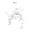
- Fig. 1 illustrates a schematic side view of a recording apparatus 1 according to this embodiment.
- the recording apparatus 1 includes a supporting shaft 2 that supports a roll R1 of a recording medium P on which recording is to be performed.
- the supporting shaft 2 of the recording apparatus 1 of this embodiment rotates in a rotation direction C when the recording medium P is transported in a transport direction A.
- a roll of the recording medium P which is wound so that a recording surface of the medium P faces outward is used in this embodiment; however, when a roll of the recording medium P which is wound so that the recording surface of the medium P faces inward is used, the supporting shaft 2 may rotate in a direction opposite to the rotation direction C in which a length of the roll R1 is fed.
- the recording apparatus 1 of this embodiment employs a roll of the recording medium serving as the recording medium P; however, the recording apparatus 1 is not limited to the recording apparatus employing such a roll of the recording medium.
- the recording medium may be individual sheets of paper.
- the recording apparatus 1 of this embodiment includes a transport mechanism 11 including a plurality of transporting rollers (not shown) that transport the recording medium P in the transport direction A.
- the transport mechanism 11 has a platen heater 5 that can heat the recording medium P supported on a platen 3.
- the platen heater 5 in this embodiment is an infrared heater that is disposed at a position facing the platen 3 and can heat the surface of the recording medium P from 35°C to 50°C; however, the platen heater 5 is not limited to such a heater and may be a heater that can heat the recording medium P from the platen 3 side. In this case, a preferable wavelength of infrared rays falls within a range of 0.76 to 1000 ⁇ m.
- infrared rays are classified into near-infrared rays, mid-infrared rays, and far-infrared rays, which have approximate wavelengths falling within the ranges of 0.78 to 2.5 ⁇ m, 2.5 to 4.0 ⁇ m, and 4.0 to 1000 ⁇ m, respectively, although classification criteria may vary. Above all things, it is preferable that mid-infrared rays be used.
- the recording apparatus 1 of this embodiment includes a recording mechanism 12.
- the recording mechanism 12 performs recording by reciprocal scanning of a recording head 4, functioning as a recording section incorporated in a carriage (not shown), in a direction B intersecting with the transport direction A of the recording medium P and by discharging inks from a plurality of nozzles in the nozzle face F.
- the recording apparatus 1 of this embodiment includes the recording mechanism 12 that performs recording by reciprocal scanning of the recording head 4; however, as described below in a fifth embodiment, the recording apparatus 1 may be a recording apparatus including a so-called line head provided with a plurality of nozzles for discharging inks in the direction B intersecting with the transport direction A.
- a line head is a recording head used in a recording apparatus in which a nozzle region formed along the direction B intersecting with the transport direction A of the recording medium P is arranged so as to be able to cover the entire recording medium in the direction B, and one of the recording head and the recording medium is fixed and the other one is moved for image formation.
- the nozzle region of the line head in the direction B does not have to cover, in the direction B, the entire recording medium P on which the recording apparatus operates.
- the nozzle region of the recording head be arranged so as to cover the entire recording medium P in the direction B intersecting with the transport direction A of the recording medium P and both the recording head and the recording medium move for image formation.
- the recording apparatus 1 of this embodiment includes the carriage that incorporates a static eliminator 8 that eliminates static electricity from the recording medium P and a moving section 9 that moves the static eliminator 8 in a direction D with respect to the recording head 4.
- the direction D is parallel to a vertically upward direction Z
- the transport direction A of the recording medium P on the platen 3 is a horizontal direction Y from a rear side toward a front side of the recording apparatus 1
- the direction B in which the recording head 4 reciprocates is parallel to a direction X perpendicular to the vertically upward direction Z and the direction Y.
- the recording apparatus 1 is not limited to such a configuration.
- the recording apparatus 1 of this embodiment includes the recording head 4 that performs recording on the recording medium P, the static eliminator 8 that eliminates static electricity from the recording medium P, and the moving section 9 that moves the static eliminator 8 with respect to the recording head 4. That is, this configuration can cause the moving section 9 to modify the relative positions of the static eliminator 8 and the recording head 4.
- the static eliminator 8 may be moved depending on the thickness of the recording medium P and the location at which it is desired to eliminate static electricity. Therefore, this configuration may efficiently inhibit contamination of the recording medium P as a result of airborne matter such as dirt, dust, and ink mist attaching to the electrostatically charged recording medium P.
- An optical sensor 14 functioning as a detecting section that detects the distance between the recording medium P and the recording head 4 is disposed at an end of the recording head 4 in the direction B.
- the controller 20 described below controls the moving section 9 so as to move the static eliminator 8 with respect to the recording head 4 in the direction D toward and away from the recording medium P depending on the distance detected by the optical sensor 14.
- the static eliminator 8 is moved with respect to the recording head 4 in the direction D toward and away from each of the recording media P depending on the thickness of the recording medium P so that the distance between the recording medium P and the static eliminator 8 becomes appropriate.
- the distance between the recording medium P and the recording head 4 refers to the amount of clearance between the nozzle face F and the surface of the recording medium P to be printed.
- the recording apparatus 1 of this embodiment includes a transport mechanism 11 functioning as a transport section that transports the recording medium P.
- the recording head 4 has a nozzle face F in which the nozzles for discharging inks are disposed.
- the recording apparatus 1 of this embodiment has a carriage that incorporates the recording head 4 and reciprocates in the direction B intersecting with the transport direction of the recording medium P.
- the recording medium P becomes electrostatically charged and thus airborne ink mist easily attaches to the recording medium P.
- the recording apparatus 1 is an ink jet recording apparatus, static electricity may be efficiently eliminated from the recording medium and therefore contamination of the recording medium caused by attached ink mist may be efficiently inhibited.
- the static eliminator 8 is incorporated in the carriage and consequently efficiently eliminates static electricity from the recording medium P immediately before the recording head 4 discharges ink, whereby contamination of the recording medium P caused by attached ink mist may be efficiently inhibited.
- a drying mechanism 13 that dries the recording medium P transported on a medium supporting section 6, by an afterheater 7 constituted by an infrared heater functioning as a drying section, is provided downstream of the transport mechanism 11 and the recording mechanism 12 in the transport direction A of the recording medium P.
- the afterheater 7 is an infrared heater that can heat the surface of the recording medium P from 60°C to 120°C in order to dry the inks used in the recording apparatus 1 of this embodiment, but is not limited to such a heater.
- the drying section may be a blower or the like such as a fan, other than a heating device such as an infrared heater.
- a winding shaft 10 that can wind the recording medium P into a roll R2 is provided downstream of the drying mechanism 13 in the transport direction A of the recording medium P.
- a roll of the recording medium P which is wound so that a recording surface of the medium P faces outward is used, whereby the winding shaft 10 rotates in the rotation direction C to wind the recording medium P.
- the winding shaft 10 rotates in a direction opposite to the rotation direction C so as to wind the roll R1.
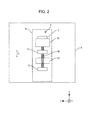
- Fig. 2 is a schematic rear view illustrating the moving section 9 for the static eliminator 8 in the recording apparatus 1 of this embodiment.
- the static eliminator 8 is illustrated in broken lines for easy understanding of the configuration of the moving section 9.
- a traveling nut 19 is attached to the static eliminator 8.
- a worm screw 18 is screwed into the traveling nut 19.
- the worm screw 18 is joined to the rotation shaft of the static eliminator moving motor 16 which is attached to the recording head 4 (and hence the carriage) similarly to supporting sections 17 and is rotatable in a normal direction and a reverse direction. That is, the worm screw 18 is rotatably fixed with respect to the recording head 4.
- the static eliminator moving motor 16 is driven to cause the worm screw 18 to rotate in the normal direction and the reverse direction, whereby the static eliminator 8 moves with respect to the recording head 4 in the direction D.
- the static eliminator moving motor 16 is provided with a rotary encoder 15 that detects the amount of rotation of the worm screw 18 in the normal direction and the reverse direction.
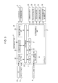
- Fig. 3 is a block diagram of the recording apparatus 1 of this embodiment.
- the controller 20 includes a CPU 21 that controls the whole recording apparatus 1.
- the CPU 21 is connected via a system bus 22 to a ROM 23 that stores a variety of control programs to be executed by the CPU 21 and the like and a RAM 24 that may temporarily store data.
- the CPU 21 is also connected via the system bus 22 to a head driving unit 25 for driving the recording head 4.
- the CPU 21 is also connected via the system bus 22 to a heater driving unit 26 for driving the platen heater 5 and the afterheater 7.
- the CPU 21 is also connected via the system bus 22 to a motor driving unit 27 for driving a carriage motor 28, a transport motor 29, a feeding motor 30, a winding motor 31, and a static eliminator moving motor 16.
- the carriage motor 28 is a motor for moving the carriage incorporating the recording head 4.
- the transport motor 29 is a motor for driving a plurality of transporting rollers disposed on the transport mechanism 11.
- the feeding motor 30, is a rotation mechanism for the supporting shaft 2, and is a motor for driving the supporting shaft 2 so as to feed the recording medium P into the transport mechanism 11.
- the winding motor 31 is a driving motor for rotating the winding shaft 10.
- the static eliminator moving motor 16 is a motor for rotating the worm screw 18 in order to move the static eliminator 8 with respect to the recording head 4 in the direction D.
- the CPU 21 is connected via the system bus 22 to an input/output section 32 connected to a PC 33 and the optical sensor 14 for sending/receiving data such as recording data or the like and signals.
- the CPU 21 is connected via the system bus 22 to a static eliminator driving unit 40 for driving the static eliminator 8.
- the controller 20 controls the static eliminator driving unit 40 so as to control the driving of the static eliminator 8.
- controlling the driving of the static eliminator 8 includes, other than on/off control of the static eliminator 8, for example, control of the intensity of the operation of the static eliminator 8 by following an instruction inputted by a user through the PC 33, or the like.
- the controller 20 controls the driving of the static eliminator 8 so that static electricity is efficiently eliminated from the recording medium P, and for example, the static eliminator 8 is turned off when the recording medium P is less likely to be electrostatically charged and elimination of static electricity is unnecessary, thereby reducing electricity costs.
- the static eliminator 8 is continuously on, the static eliminator 8 is likely to be contaminated as a result of airborne matter such as dirt, dust, and ink mist attaching to the static eliminator 8, therefore, when elimination of static electricity is unnecessary, for example, the static eliminator 8 is turned off, which inhibits the static eliminator 8 from being likely to be contaminated.
- the controller 20 may receive, from the PC 33, information on a type of the recording medium P, information on an installation location of the recording apparatus 1, information on date and time, and information on environmental humidity, and control the driving of the static eliminator 8 on the basis of at least one of information on the type of the recording medium P, information on the installation location of the recording apparatus 1, information on date and time, and information on the environmental humidity. Therefore, it may be easily recognized when the recording medium P is less likely to be electrostatically charged so that elimination of static electricity is unnecessary, on the basis of at least one of the type of the recording medium P, the installation location of the recording apparatus 1, and date and time and the environmental humidity.
- Fig. 4 is a schematic rear view illustrating the moving section 9 for the static eliminator 8 in the recording apparatus of this embodiment. Components the same as those in the above embodiment are denoted by the same numerals, and detailed description thereof will be omitted.
- the recording apparatus 1 of this embodiment has a similar configuration to the recording apparatus 1 of the first embodiment except the configuration of the moving section 9.
- the static eliminator 8 is provided with a rack 34.
- the rack 34 is engaged with a pinion 35.
- the pinion 35 is attached to a rotation shaft 36 of a static eliminator moving motor 16, which is attached to the recording head 4 (and hence the carriage).
- the pinion 35 can rotate in the normal direction and the reverse direction. That is, the pinion 35 is rotatably fixed with respect to the recording head 4.
- the static eliminator moving motor 16 is driven to cause the pinion 35 to rotate in the normal direction and the reverse direction, whereby the static eliminator 8 moves with respect to the recording head 4 in the direction D.
- the static eliminator moving motor 16 is provided with a rotary encoder 15 that detects an amount of the rotation of the rotation shaft 16 in the normal direction and the reverse direction.
- Fig. 5 is a schematic plan view illustrating a position and a moving direction of a static eliminator 8 with respect to a recording head 4 in a recording apparatus in this embodiment.
- Components the same as those in the above embodiments are denoted by the same numerals, and detailed description thereof will be omitted.
- the recording apparatus 1 of this embodiment has a similar configuration to the recording apparatus 1 of the first embodiment except the location of the static eliminator 8 with respect to the recording head 4 and the position and the moving direction of the moving section 9.
- the static eliminator 8 is disposed at one end of the recording head 4 in the direction B which is a direction in which the recording head 4 moves reciprocally.
- the recording apparatus 1 of this embodiment includes a transport mechanism 11 that transports the recording medium P.
- the moving section 9 may move the static eliminator 8 with respect to the recording head 4 in the transport direction A of the recording medium P. Therefore, the static eliminator 8 may be moved with respect to the recording head 4 to an appropriate position in the direction E parallel to the transport direction A.
- the static eliminator 8 may also be moved up or down in the direction D, for example using a mechanism as in the first or second embodiment.
- Fig. 6 is a schematic plan view illustrating a position and a moving direction of a static eliminator 8 with respect to a recording head 4 in a recording apparatus of this embodiment.
- Components the same as those in the above embodiments are denoted by the same numerals, and detailed description thereof will be omitted.
- the recording apparatus 1 of this embodiment has the same configuration as the recording apparatus 1 of the third embodiment except that both the static eliminator 8 and the moving section 9 are disposed at each end of the recording head 4 in the direction B.
- the recording apparatus 1 of this embodiment includes the static eliminator 8 and the moving section 9 both disposed at each end of the recording head 4 in the direction B.
- Each of the moving sections 9 may move the corresponding static eliminator 8 with respect to the recording head 4 in the direction E parallel to the transport direction A.
- the static eliminator 8 is incorporated at each end of the recording head 4 in the direction B. Therefore, whichever direction along the direction B (either the leftward direction or the rightward direction in Fig. 6 ) the static eliminator 8 moves, the static eliminator 8 may efficiently eliminate static electricity from the recording medium P in an appropriate position in the transport direction A with respect to the recording head 4 immediately before the recording head 4 discharges ink. Therefore, contamination of the recording medium P caused by attached ink mist may be efficiently inhibited.
- the static eliminator 8 may also be moved up or down in the direction D, for example using a mechanism as in the first or second embodiment.
- Fig. 7 is a schematic plan view illustrating a recording apparatus of this embodiment. Components the same as those in the above embodiments are denoted by the same numerals, and detailed description thereof will be omitted.
- the recording apparatus 1 of this embodiment has the same configuration as the recording apparatus 1 of the first embodiment, except that the recording apparatus 1 includes a line head 37 functioning as a recording section and a static eliminator 38 extending in a direction intersecting with the transport direction A.
- the recording apparatus 1 of this embodiment includes the line head 37 functioning as a recording section and the static eliminator 38 extending in a direction intersecting with the transport direction A.
- Two moving sections 39 may move the static eliminator 38 with respect to the line head 37 in the direction D, but each moving section 39 recording apparatus 1 of this embodiment has a similar configuration to the moving section 9 in the recording apparatus 1 of the first or second embodiment.
- the recording apparatus 1 in such a configuration may also efficiently inhibit contamination of the recording medium P as a result of airborne matter such as dirt, dust, and ink mist attaching to the recording medium P.
- the recording apparatus of the above embodiments 1, 2, and 5 includes the static eliminator 8 upstream of the recording head in the transport direction A of the recording medium P.
- the recording apparatus having a configuration in which the recording medium P is set at a setting position located downstream of the recording head in the transport direction A, subsequently is moved upstream of the recording head in the transport direction A, and subsequently transported may include the static eliminator 8 downstream of the recording head in the transport direction A.
- the recording apparatus may move the static eliminator with respect to the recording section in one of the direction D and the direction E; however, the static eliminator may be moved in both the direction D and the direction E, or may be moved in another direction.
Landscapes
- Ink Jet (AREA)
- Accessory Devices And Overall Control Thereof (AREA)
- Fax Reproducing Arrangements (AREA)
Abstract
Description
- The present invention relates to a recording apparatus.
- Recording apparatuses for performing recording on recording media have been used. In such recording apparatuses, the recording medium may be contaminated as a result of airborne matter such as dirt, dust, and ink mist attaching to the electrostatically charged recording medium. Consequently, for example,
JP-A-2013-107330 - However, in recent years, recording media having various thicknesses have been used, and in the recording apparatus of the related-art such as disclosed in
JP-A-2013-107330 - In addition, the appropriate distance between the recording section and the static eliminator in the transport direction of the recording medium may vary with the type of recording medium.
- In the recording apparatus disclosed in
JP-A-2013-107330 - An advantage of some aspects of the invention is to efficiently inhibit contamination of the recording medium as a result of airborne matter such as dirt, dust, and ink mist attaching to the electrostatically charged recording medium.
- According to an aspect of the invention, a recording apparatus includes: a recording section that performs recording on a recording medium; a static eliminator that eliminates static electricity from the recording medium; and a moving section that moves the static eliminator with respect to the recording section.
- According to this aspect, the recording apparatus includes the moving section which moves the static eliminator with respect to the recording section. Thus, the static eliminator may be moved depending on the thickness of the recording medium and the location at which it is desired to eliminate static electricity. Therefore, contamination of the recording medium as a result of airborne matter such as dirt, dust, and ink mist attaching to the electrostatically charged recording medium may be efficiently inhibited.
- It is preferable that the recording apparatus include a detecting section that detects a distance between the recording medium and the recording section, in which the moving section moves the static eliminator toward and away from the recording medium depending on the distance detected by the detecting section.
- According to the above, the moving section moves the static eliminator in the direction toward and away from the recording medium depending on the distance detected by the detecting section. Thus, even if the various recording media having different thicknesses are used, the static eliminator is moved toward and away from the recording medium depending on the thickness of each recording medium, so that the distance between the recording medium and the static eliminator may be appropriate.
- As used herein, "the distance between the recording medium and the recording section" means the distance between the surface of the recording medium to be printed and, for example, the recording section that performs recording like a nozzle face of an ink jet recording head.
- It is preferable that the recording apparatus include a transport section that transports the recording medium, in which the moving section moves the static eliminator in a transport direction of the recording medium.
- According to the above, the moving section moves the static eliminator in the transport direction of the recording medium. Thus, the static eliminator may be moved to an appropriate position in the transport direction.
- It is preferable that the recording apparatus include a transport section that transports the recording medium, in which the recording section includes a recording head having a nozzle face in which nozzles for discharging inks are disposed and a carriage that incorporates the recording head and that reciprocally moves in a direction intersecting with the transport direction of the recording medium.
- In an ink jet recording apparatus that incorporates the recording head having the nozzle face in which the nozzles for discharging inks are disposed and performs recording by reciprocally moving the recording head in the intersecting direction, the recording medium becomes electrostatically charged and, as a result, airborne ink mist easily attaches to the recording medium.
- However, according to the above, even in the recording apparatus having such a configuration, static electricity may be efficiently eliminated from the recording medium and contamination of the recording medium caused by attached ink mist may be efficiently inhibited.
- It is preferable that the recording section include a recording head having a nozzle face in which nozzles for discharging inks are disposed, and a carriage that incorporates the recording head and reciprocally moves in a direction intersecting with the transport direction of the recording medium.
- In the ink jet recording apparatus that incorporates the recording head having the nozzle face in which the nozzles for discharging inks are disposed and that performs recording by reciprocal movement of the recording head in the intersecting direction, the recording medium becomes electrostatically charged and, as a result, airborne ink mist easily attaches to the recording medium.
- However, according to the above, even in the recording apparatus having such a configuration, static electricity may be efficiently eliminated from the recording medium and contamination of the recording medium caused by attached ink mist may be efficiently inhibited.
- It is preferable that the static eliminator be incorporated in the carriage.
- According to the above, the static eliminator is incorporated in the carriage. Thus, static electricity may be efficiently eliminated from the recording medium immediately before the recording head discharges inks, whereby contamination of the recording medium caused by attached ink mist may be efficiently inhibited.
- It is preferable that the static eliminator be provided at each end of the recording head in the intersecting direction.
- According to the above, the static eliminator is provided at each end of the recording head in the intersecting direction. Thus, whichever direction along the intersecting direction the static eliminator moves, the static eliminator may efficiently eliminate static electricity from the recording medium in an appropriate position with respect to the recording section in the transport direction immediately before the recording head discharges inks. Therefore, contamination of the recording medium caused by attached ink mist may be efficiently inhibited.
- It is preferable that the recording apparatus include a controller that controls driving of the static eliminator.
- As used herein, "controlling driving of the static eliminator" includes, other than on/off control of the static eliminator, control of the intensity of the operation of the static eliminator or the like.
- According to the above, the recording apparatus includes the controller that controls the driving of the static eliminator. Thus, static electricity is efficiently eliminated from the recording medium, and when the recording medium is less likely electrostatically charged and elimination of static electricity is unnecessary, the static eliminator is, for example, turned off to reduce an electricity expense. In addition, when the static eliminator is continuously on, the static eliminator is likely to be contaminated as a result of airborne matter such as dirt, dust, and ink mist attaching to the static eliminator. However, when elimination of static electricity is unnecessary, for example, the static eliminator is turned off, which inhibits the static eliminator from being likely to be contaminated.
- It is preferable that the controller control the driving of the static eliminator on the basis of at least one of information on a type of the recording medium, information on an installation location of the recording apparatus, information on date and time, and information on environmental humidity.
- According to the above, the controller controls the driving of the static eliminator on the basis of at least one of information on a type of the recording medium, information on an installation location of the recording apparatus, information on date and time, and information on environmental humidity. Therefore, it may be easily recognized when the recording medium is less likely to be electrostatically charged and accordingly elimination of static electricity is unnecessary, on the basis of at least one of the type of the recording medium, the installation location of the recording apparatus, and date and time and the environmental humidity.
- Embodiments of the invention will now be described by way of example only with reference to the accompanying drawings, wherein like numbers reference like elements.
-
Fig. 1 is a schematic side view illustrating a recording apparatus according to a first embodiment of the invention. -
Fig. 2 is a schematic rear view illustrating a moving section of a static eliminator in the recording apparatus according to the first embodiment of the invention. -
Fig. 3 is a block diagram of the recording apparatus according to the first embodiment of the invention. -
Fig. 4 is a schematic rear view illustrating a moving section of a static eliminator in a recording apparatus according to a second embodiment of the invention. -
Fig. 5 is a schematic plan view illustrating a position and a moving direction of a static eliminator with respect to a recording section of a recording apparatus according to a third embodiment of the invention. -
Fig. 6 is a schematic plan view illustrating a position and a moving direction of a static eliminator with respect to a recording section of a recording apparatus according to a fourth embodiment of the invention. -
Fig. 7 is a schematic plan view illustrating a recording apparatus according to a fifth embodiment of the invention. - A recording apparatus according to an embodiment of the invention will be described in detail with reference to the accompanying drawings.
- First, a recording apparatus according to the first embodiment of the invention will be described.
-
Fig. 1 illustrates a schematic side view of a recording apparatus 1 according to this embodiment. - The recording apparatus 1 according to this embodiment includes a supporting
shaft 2 that supports a roll R1 of a recording medium P on which recording is to be performed. The supportingshaft 2 of the recording apparatus 1 of this embodiment rotates in a rotation direction C when the recording medium P is transported in a transport direction A. A roll of the recording medium P which is wound so that a recording surface of the medium P faces outward is used in this embodiment; however, when a roll of the recording medium P which is wound so that the recording surface of the medium P faces inward is used, the supportingshaft 2 may rotate in a direction opposite to the rotation direction C in which a length of the roll R1 is fed. - In addition, the recording apparatus 1 of this embodiment employs a roll of the recording medium serving as the recording medium P; however, the recording apparatus 1 is not limited to the recording apparatus employing such a roll of the recording medium. For example, the recording medium may be individual sheets of paper.
- In addition, the recording apparatus 1 of this embodiment includes a
transport mechanism 11 including a plurality of transporting rollers (not shown) that transport the recording medium P in the transport direction A. Thetransport mechanism 11 has aplaten heater 5 that can heat the recording medium P supported on aplaten 3. - The
platen heater 5 in this embodiment is an infrared heater that is disposed at a position facing theplaten 3 and can heat the surface of the recording medium P from 35°C to 50°C; however, theplaten heater 5 is not limited to such a heater and may be a heater that can heat the recording medium P from theplaten 3 side. In this case, a preferable wavelength of infrared rays falls within a range of 0.76 to 1000 µm. In general, infrared rays are classified into near-infrared rays, mid-infrared rays, and far-infrared rays, which have approximate wavelengths falling within the ranges of 0.78 to 2.5 µm, 2.5 to 4.0 µm, and 4.0 to 1000 µm, respectively, although classification criteria may vary. Above all things, it is preferable that mid-infrared rays be used. - In addition, the recording apparatus 1 of this embodiment includes a
recording mechanism 12. Therecording mechanism 12 performs recording by reciprocal scanning of arecording head 4, functioning as a recording section incorporated in a carriage (not shown), in a direction B intersecting with the transport direction A of the recording medium P and by discharging inks from a plurality of nozzles in the nozzle face F. The recording apparatus 1 of this embodiment includes therecording mechanism 12 that performs recording by reciprocal scanning of therecording head 4; however, as described below in a fifth embodiment, the recording apparatus 1 may be a recording apparatus including a so-called line head provided with a plurality of nozzles for discharging inks in the direction B intersecting with the transport direction A. - As used herein, "a line head" is a recording head used in a recording apparatus in which a nozzle region formed along the direction B intersecting with the transport direction A of the recording medium P is arranged so as to be able to cover the entire recording medium in the direction B, and one of the recording head and the recording medium is fixed and the other one is moved for image formation. The nozzle region of the line head in the direction B does not have to cover, in the direction B, the entire recording medium P on which the recording apparatus operates.
- It is also possible that the nozzle region of the recording head be arranged so as to cover the entire recording medium P in the direction B intersecting with the transport direction A of the recording medium P and both the recording head and the recording medium move for image formation.
- The recording apparatus 1 of this embodiment includes the carriage that incorporates a
static eliminator 8 that eliminates static electricity from the recording medium P and a movingsection 9 that moves thestatic eliminator 8 in a direction D with respect to therecording head 4. In this embodiment, the direction D is parallel to a vertically upward direction Z, the transport direction A of the recording medium P on theplaten 3 is a horizontal direction Y from a rear side toward a front side of the recording apparatus 1, and the direction B in which therecording head 4 reciprocates is parallel to a direction X perpendicular to the vertically upward direction Z and the direction Y. However, the recording apparatus 1 is not limited to such a configuration. - As described above, the recording apparatus 1 of this embodiment includes the
recording head 4 that performs recording on the recording medium P, thestatic eliminator 8 that eliminates static electricity from the recording medium P, and the movingsection 9 that moves thestatic eliminator 8 with respect to therecording head 4. That is, this configuration can cause the movingsection 9 to modify the relative positions of thestatic eliminator 8 and therecording head 4. Thus, thestatic eliminator 8 may be moved depending on the thickness of the recording medium P and the location at which it is desired to eliminate static electricity. Therefore, this configuration may efficiently inhibit contamination of the recording medium P as a result of airborne matter such as dirt, dust, and ink mist attaching to the electrostatically charged recording medium P. - An
optical sensor 14 functioning as a detecting section that detects the distance between the recording medium P and therecording head 4 is disposed at an end of therecording head 4 in the direction B. Thecontroller 20 described below (seeFig. 3 ) controls the movingsection 9 so as to move thestatic eliminator 8 with respect to therecording head 4 in the direction D toward and away from the recording medium P depending on the distance detected by theoptical sensor 14. - Thus, even if various recording media P having different thickness are used, the
static eliminator 8 is moved with respect to therecording head 4 in the direction D toward and away from each of the recording media P depending on the thickness of the recording medium P so that the distance between the recording medium P and thestatic eliminator 8 becomes appropriate. - In this embodiment, the distance between the recording medium P and the
recording head 4 refers to the amount of clearance between the nozzle face F and the surface of the recording medium P to be printed. - As described above, the recording apparatus 1 of this embodiment includes a
transport mechanism 11 functioning as a transport section that transports the recording medium P. Therecording head 4 has a nozzle face F in which the nozzles for discharging inks are disposed. The recording apparatus 1 of this embodiment has a carriage that incorporates therecording head 4 and reciprocates in the direction B intersecting with the transport direction of the recording medium P. - In the ink jet recording apparatus that incorporates the
recording head 4 having the nozzle face F in which the nozzles discharging inks are disposed and performs recording by reciprocal movement of therecording head 4 in the direction B, the recording medium P becomes electrostatically charged and thus airborne ink mist easily attaches to the recording medium P. - However, in this embodiment, even if the recording apparatus 1 is an ink jet recording apparatus, static electricity may be efficiently eliminated from the recording medium and therefore contamination of the recording medium caused by attached ink mist may be efficiently inhibited.
- As described above, the
static eliminator 8 is incorporated in the carriage and consequently efficiently eliminates static electricity from the recording medium P immediately before therecording head 4 discharges ink, whereby contamination of the recording medium P caused by attached ink mist may be efficiently inhibited. - A
drying mechanism 13 that dries the recording medium P transported on amedium supporting section 6, by anafterheater 7 constituted by an infrared heater functioning as a drying section, is provided downstream of thetransport mechanism 11 and therecording mechanism 12 in the transport direction A of the recording medium P. Theafterheater 7 is an infrared heater that can heat the surface of the recording medium P from 60°C to 120°C in order to dry the inks used in the recording apparatus 1 of this embodiment, but is not limited to such a heater. In addition, the drying section may be a blower or the like such as a fan, other than a heating device such as an infrared heater. - In addition, a winding
shaft 10 that can wind the recording medium P into a roll R2 is provided downstream of thedrying mechanism 13 in the transport direction A of the recording medium P. In this embodiment, a roll of the recording medium P which is wound so that a recording surface of the medium P faces outward is used, whereby the windingshaft 10 rotates in the rotation direction C to wind the recording medium P. On the other hand, when a roll of the recording medium P which is wound so that the recording surface of the medium P faces inward is used, the windingshaft 10 rotates in a direction opposite to the rotation direction C so as to wind the roll R1. - A configuration of the moving
section 9 for thestatic eliminator 8 in the recording apparatus 1 of this embodiment will be described. -
Fig. 2 is a schematic rear view illustrating the movingsection 9 for thestatic eliminator 8 in the recording apparatus 1 of this embodiment. - The
static eliminator 8 is illustrated in broken lines for easy understanding of the configuration of the movingsection 9. - In
Fig. 2 , a travelingnut 19 is attached to thestatic eliminator 8. Aworm screw 18 is screwed into the travelingnut 19. Theworm screw 18 is joined to the rotation shaft of the staticeliminator moving motor 16 which is attached to the recording head 4 (and hence the carriage) similarly to supportingsections 17 and is rotatable in a normal direction and a reverse direction. That is, theworm screw 18 is rotatably fixed with respect to therecording head 4. Then, the staticeliminator moving motor 16 is driven to cause theworm screw 18 to rotate in the normal direction and the reverse direction, whereby thestatic eliminator 8 moves with respect to therecording head 4 in the direction D. - The static
eliminator moving motor 16 is provided with arotary encoder 15 that detects the amount of rotation of theworm screw 18 in the normal direction and the reverse direction. - Electric configuration of the recording apparatus 1 of this embodiment will be described.
-
Fig. 3 is a block diagram of the recording apparatus 1 of this embodiment. - The
controller 20 includes aCPU 21 that controls the whole recording apparatus 1. TheCPU 21 is connected via asystem bus 22 to aROM 23 that stores a variety of control programs to be executed by theCPU 21 and the like and aRAM 24 that may temporarily store data. - The
CPU 21 is also connected via thesystem bus 22 to ahead driving unit 25 for driving therecording head 4. - The
CPU 21 is also connected via thesystem bus 22 to aheater driving unit 26 for driving theplaten heater 5 and theafterheater 7. - The
CPU 21 is also connected via thesystem bus 22 to amotor driving unit 27 for driving acarriage motor 28, atransport motor 29, a feedingmotor 30, a windingmotor 31, and a staticeliminator moving motor 16. - The
carriage motor 28 is a motor for moving the carriage incorporating therecording head 4. Thetransport motor 29 is a motor for driving a plurality of transporting rollers disposed on thetransport mechanism 11. The feedingmotor 30, is a rotation mechanism for the supportingshaft 2, and is a motor for driving the supportingshaft 2 so as to feed the recording medium P into thetransport mechanism 11. The windingmotor 31 is a driving motor for rotating the windingshaft 10. The staticeliminator moving motor 16 is a motor for rotating theworm screw 18 in order to move thestatic eliminator 8 with respect to therecording head 4 in the direction D. - In addition, the
CPU 21 is connected via thesystem bus 22 to an input/output section 32 connected to aPC 33 and theoptical sensor 14 for sending/receiving data such as recording data or the like and signals. - The
CPU 21 is connected via thesystem bus 22 to a staticeliminator driving unit 40 for driving thestatic eliminator 8. Thecontroller 20 controls the staticeliminator driving unit 40 so as to control the driving of thestatic eliminator 8. - As used herein, "controlling the driving of the
static eliminator 8" includes, other than on/off control of thestatic eliminator 8, for example, control of the intensity of the operation of thestatic eliminator 8 by following an instruction inputted by a user through thePC 33, or the like. - In the recording apparatus 1 of this embodiment, the
controller 20 controls the driving of thestatic eliminator 8 so that static electricity is efficiently eliminated from the recording medium P, and for example, thestatic eliminator 8 is turned off when the recording medium P is less likely to be electrostatically charged and elimination of static electricity is unnecessary, thereby reducing electricity costs. In addition, if thestatic eliminator 8 is continuously on, thestatic eliminator 8 is likely to be contaminated as a result of airborne matter such as dirt, dust, and ink mist attaching to thestatic eliminator 8, therefore, when elimination of static electricity is unnecessary, for example, thestatic eliminator 8 is turned off, which inhibits thestatic eliminator 8 from being likely to be contaminated. - The
controller 20 may receive, from thePC 33, information on a type of the recording medium P, information on an installation location of the recording apparatus 1, information on date and time, and information on environmental humidity, and control the driving of thestatic eliminator 8 on the basis of at least one of information on the type of the recording medium P, information on the installation location of the recording apparatus 1, information on date and time, and information on the environmental humidity. Therefore, it may be easily recognized when the recording medium P is less likely to be electrostatically charged so that elimination of static electricity is unnecessary, on the basis of at least one of the type of the recording medium P, the installation location of the recording apparatus 1, and date and time and the environmental humidity. - A recording apparatus of a second embodiment will be described in detail with reference to the accompanying drawings.
-
Fig. 4 is a schematic rear view illustrating the movingsection 9 for thestatic eliminator 8 in the recording apparatus of this embodiment. Components the same as those in the above embodiment are denoted by the same numerals, and detailed description thereof will be omitted. - The recording apparatus 1 of this embodiment has a similar configuration to the recording apparatus 1 of the first embodiment except the configuration of the moving
section 9. - As illustrated in
Fig. 4 , in this embodiment, thestatic eliminator 8 is provided with arack 34. Therack 34 is engaged with apinion 35. Thepinion 35 is attached to arotation shaft 36 of a staticeliminator moving motor 16, which is attached to the recording head 4 (and hence the carriage). Thepinion 35 can rotate in the normal direction and the reverse direction. That is, thepinion 35 is rotatably fixed with respect to therecording head 4. Then, the staticeliminator moving motor 16 is driven to cause thepinion 35 to rotate in the normal direction and the reverse direction, whereby thestatic eliminator 8 moves with respect to therecording head 4 in the direction D. - The static
eliminator moving motor 16 is provided with arotary encoder 15 that detects an amount of the rotation of therotation shaft 16 in the normal direction and the reverse direction. - A recording apparatus of a third embodiment will be described in detail with reference to the accompanying drawings.
-
Fig. 5 is a schematic plan view illustrating a position and a moving direction of astatic eliminator 8 with respect to arecording head 4 in a recording apparatus in this embodiment. Components the same as those in the above embodiments are denoted by the same numerals, and detailed description thereof will be omitted. - The recording apparatus 1 of this embodiment has a similar configuration to the recording apparatus 1 of the first embodiment except the location of the
static eliminator 8 with respect to therecording head 4 and the position and the moving direction of the movingsection 9. - As illustrated in
Fig. 5 , in the recording apparatus 1 of this embodiment, thestatic eliminator 8 is disposed at one end of therecording head 4 in the direction B which is a direction in which therecording head 4 moves reciprocally. The movingsection 9, which has the same configuration as the first embodiment and which turns 90 degrees from the position of the first embodiment, may move thestatic eliminator 8 with respect to therecording head 4 in a direction E parallel to the transport direction A. - In other words, the recording apparatus 1 of this embodiment includes a
transport mechanism 11 that transports the recording medium P. The movingsection 9 may move thestatic eliminator 8 with respect to therecording head 4 in the transport direction A of the recording medium P. Therefore, thestatic eliminator 8 may be moved with respect to therecording head 4 to an appropriate position in the direction E parallel to the transport direction A. - Fourth Embodiment (
Fig. 6 ). Preferably, thestatic eliminator 8 may also be moved up or down in the direction D, for example using a mechanism as in the first or second embodiment. - The recording apparatus of a fourth embodiment will be described in detail with reference to the accompanying drawings.
-
Fig. 6 is a schematic plan view illustrating a position and a moving direction of astatic eliminator 8 with respect to arecording head 4 in a recording apparatus of this embodiment. Components the same as those in the above embodiments are denoted by the same numerals, and detailed description thereof will be omitted. - The recording apparatus 1 of this embodiment has the same configuration as the recording apparatus 1 of the third embodiment except that both the
static eliminator 8 and the movingsection 9 are disposed at each end of therecording head 4 in the direction B. - As illustrated in
Fig. 6 , the recording apparatus 1 of this embodiment includes thestatic eliminator 8 and the movingsection 9 both disposed at each end of therecording head 4 in the direction B. Each of the movingsections 9 may move the correspondingstatic eliminator 8 with respect to therecording head 4 in the direction E parallel to the transport direction A. - In other words, in the recording apparatus 1 of this embodiment, the
static eliminator 8 is incorporated at each end of therecording head 4 in the direction B. Therefore, whichever direction along the direction B (either the leftward direction or the rightward direction inFig. 6 ) thestatic eliminator 8 moves, thestatic eliminator 8 may efficiently eliminate static electricity from the recording medium P in an appropriate position in the transport direction A with respect to therecording head 4 immediately before therecording head 4 discharges ink. Therefore, contamination of the recording medium P caused by attached ink mist may be efficiently inhibited. Preferably, thestatic eliminator 8 may also be moved up or down in the direction D, for example using a mechanism as in the first or second embodiment. - The recording apparatus of a fifth embodiment will be described in detail with reference to the accompanying drawings.
-
Fig. 7 is a schematic plan view illustrating a recording apparatus of this embodiment. Components the same as those in the above embodiments are denoted by the same numerals, and detailed description thereof will be omitted. - The recording apparatus 1 of this embodiment has the same configuration as the recording apparatus 1 of the first embodiment, except that the recording apparatus 1 includes a
line head 37 functioning as a recording section and a static eliminator 38 extending in a direction intersecting with the transport direction A. - As illustrated in
Fig. 7 , the recording apparatus 1 of this embodiment includes theline head 37 functioning as a recording section and the static eliminator 38 extending in a direction intersecting with the transport direction A. Two movingsections 39 may move the static eliminator 38 with respect to theline head 37 in the direction D, but each movingsection 39 recording apparatus 1 of this embodiment has a similar configuration to the movingsection 9 in the recording apparatus 1 of the first or second embodiment. - The recording apparatus 1 in such a configuration may also efficiently inhibit contamination of the recording medium P as a result of airborne matter such as dirt, dust, and ink mist attaching to the recording medium P.
- The recording apparatus of the
above embodiments static eliminator 8 upstream of the recording head in the transport direction A of the recording medium P. However, for example, the recording apparatus having a configuration in which the recording medium P is set at a setting position located downstream of the recording head in the transport direction A, subsequently is moved upstream of the recording head in the transport direction A, and subsequently transported, may include thestatic eliminator 8 downstream of the recording head in the transport direction A. - In the above embodiments, the recording apparatus may move the static eliminator with respect to the recording section in one of the direction D and the direction E; however, the static eliminator may be moved in both the direction D and the direction E, or may be moved in another direction.
- The foregoing description has been given by way of example only and it will be appreciated by a person skilled in the art that modifications can be made without departing from the scope of the present invention.
Claims (9)
- A recording apparatus (1) comprising:a recording section for performing recording on a recording medium (P);a static eliminator (8) for eliminating static electricity from the recording medium; anda moving section (9) for moving the static eliminator with respect to the recording section.
- The recording apparatus according to Claim 1, further comprising:a detecting section (14) for detecting a distance between the recording medium and the recording section,wherein the moving section is adapted to move the static eliminator toward and away from the recording medium depending on the distance detected by the detecting section.
- The recording apparatus according to Claim 1 or Claim 2, further comprising:a transport section (11) for transporting the recording medium,wherein the moving section is adapted to move the static eliminator in a transport direction of the recording medium.
- The recording apparatus according to Claim 1 or Claim 2, further comprising,
a transport section (11) for transporting the recording medium,
wherein the recording section (12) includes:a recording head (4) having a nozzle face (F) in which nozzles for discharging inks are disposed; anda carriage that incorporates the recording head and reciprocally moves in a direction intersecting with the transport direction of the recording medium. - The recording apparatus according to Claim 3,
wherein the recording section (12) includes:a recording head (4) having a nozzle face (F) in which nozzles for discharging inks are disposed; anda carriage that incorporates the recording head and reciprocally moves in a direction intersecting with the transport direction of the recording medium. - The recording apparatus according to Claim 4 or Claim 5,
wherein the static eliminator is incorporated in the carriage. - The recording apparatus according to Claim 6,
wherein the static eliminator is incorporated at each end of the recording head in the intersecting direction. - The recording apparatus according to any one of the preceding claims, further comprising:a controller (20) for controlling driving of the static eliminator.
- The recording apparatus according to Claim 8,
wherein the controller is adapted to control the driving of the static eliminator using at least one of information on a type of the recording medium, information on an installation location of the recording apparatus, information on date and time, and information on environmental humidity.
Applications Claiming Priority (1)
| Application Number | Priority Date | Filing Date | Title |
|---|---|---|---|
| JP2013268719A JP6225698B2 (en) | 2013-12-26 | 2013-12-26 | Recording device |
Publications (3)
| Publication Number | Publication Date |
|---|---|
| EP2889145A2 true EP2889145A2 (en) | 2015-07-01 |
| EP2889145A3 EP2889145A3 (en) | 2016-08-31 |
| EP2889145B1 EP2889145B1 (en) | 2017-10-25 |
Family
ID=52231981
Family Applications (1)
| Application Number | Title | Priority Date | Filing Date |
|---|---|---|---|
| EP14199836.9A Not-in-force EP2889145B1 (en) | 2013-12-26 | 2014-12-22 | Recording apparatus |
Country Status (4)
| Country | Link |
|---|---|
| US (1) | US9393807B2 (en) |
| EP (1) | EP2889145B1 (en) |
| JP (1) | JP6225698B2 (en) |
| CN (1) | CN104742521B (en) |
Families Citing this family (3)
| Publication number | Priority date | Publication date | Assignee | Title |
|---|---|---|---|---|
| JP6888473B2 (en) * | 2017-08-10 | 2021-06-16 | セイコーエプソン株式会社 | Printing equipment |
| CN107584889A (en) * | 2017-10-25 | 2018-01-16 | 广东葵树生物科技股份有限公司 | A kind of packaging bag code spraying system |
| EP4659957A1 (en) * | 2023-01-31 | 2025-12-10 | FUJIFILM Corporation | Printing device and printing method |
Citations (1)
| Publication number | Priority date | Publication date | Assignee | Title |
|---|---|---|---|---|
| JP2013107330A (en) | 2011-11-22 | 2013-06-06 | Seiko I Infotech Inc | Inkjet recording apparatus and method |
Family Cites Families (27)
| Publication number | Priority date | Publication date | Assignee | Title |
|---|---|---|---|---|
| US4361845A (en) | 1981-03-16 | 1982-11-30 | International Business Machines Corporation | Device for preventing the contamination of ink jet components |
| JP3130622B2 (en) | 1992-01-16 | 2001-01-31 | 帝人株式会社 | Pad material and manufacturing method thereof |
| US5774141A (en) | 1995-10-26 | 1998-06-30 | Hewlett-Packard Company | Carriage-mounted inkjet aerosol reduction system |
| US6390618B1 (en) | 2000-01-07 | 2002-05-21 | Hewlett-Packard Company | Method and apparatus for ink-jet print zone drying |
| JP2001260481A (en) * | 2000-01-12 | 2001-09-25 | Fuji Photo Film Co Ltd | Recording device |
| JP2001328265A (en) * | 2000-05-19 | 2001-11-27 | Olympus Optical Co Ltd | Ink jet recording apparatus |
| JP2004154958A (en) | 2002-11-01 | 2004-06-03 | Canon Inc | Inkjet recording device |
| WO2005014289A1 (en) * | 2003-08-08 | 2005-02-17 | Konica Minolta Holdings, Inc. | Liquid jetting device, liquid jetting method, and method of forming wiring pattern on circuit board |
| CN101386226B (en) * | 2003-08-08 | 2012-07-04 | 柯尼卡美能达控股株式会社 | Liquid ejection apparatus, liquid ejection method, and method for forming wiring pattern of circuit board |
| JP2005131922A (en) * | 2003-10-30 | 2005-05-26 | Konica Minolta Medical & Graphic Inc | Ink jet recorder |
| JP2005271316A (en) | 2004-03-23 | 2005-10-06 | Canon Inc | Inkjet recording device |
| EP1652675B1 (en) | 2004-10-29 | 2008-09-10 | Hewlett-Packard Development Company, L.P. | Methods and apparatus for aerosol extraction in fluid ejection-devices |
| KR20070087748A (en) * | 2005-10-13 | 2007-08-29 | 삼성전자주식회사 | Recording medium ejection device and image forming device using same |
| JP2008213310A (en) | 2007-03-05 | 2008-09-18 | Canon Inc | Recording device |
| JP2009007119A (en) * | 2007-06-28 | 2009-01-15 | Canon Inc | Image forming apparatus |
| JP5159212B2 (en) * | 2007-08-27 | 2013-03-06 | キヤノン株式会社 | Inkjet recording device |
| JP5195397B2 (en) | 2008-12-24 | 2013-05-08 | 大日本印刷株式会社 | Static eliminator for rotary press |
| IL196203A (en) * | 2008-12-25 | 2012-12-31 | Matan Digital Printing Ltd | Method of preventing electrostatic charge build up on a print media and printer using the method |
| WO2010138126A1 (en) * | 2009-05-29 | 2010-12-02 | Hewlett-Packard Development Company, L.P. | Inkjet printing apparatus and method thereof |
| JP5407697B2 (en) | 2009-09-18 | 2014-02-05 | 富士ゼロックス株式会社 | Image forming apparatus |
| JP5633671B2 (en) * | 2009-11-11 | 2014-12-03 | セイコーエプソン株式会社 | Liquid ejector |
| JP2011110788A (en) * | 2009-11-26 | 2011-06-09 | Seiko Epson Corp | Liquid jetting apparatus |
| CN201587175U (en) * | 2010-01-15 | 2010-09-22 | 肖昆 | Universal spray-drawing machine |
| JP5418279B2 (en) * | 2010-02-16 | 2014-02-19 | セイコーエプソン株式会社 | Liquid ejector |
| JP2011183746A (en) * | 2010-03-10 | 2011-09-22 | Seiko Epson Corp | Liquid ejector |
| CN202702892U (en) * | 2012-05-18 | 2013-01-30 | 上海运安制版有限公司 | Ink jet head height automatic regulation device for tile ink jet system |
| CN203293721U (en) * | 2013-05-15 | 2013-11-20 | 济南优诺思喷印设备有限公司 | Printer dolly with adjustable height |
-
2013
- 2013-12-26 JP JP2013268719A patent/JP6225698B2/en not_active Expired - Fee Related
-
2014
- 2014-12-15 US US14/570,563 patent/US9393807B2/en not_active Expired - Fee Related
- 2014-12-22 EP EP14199836.9A patent/EP2889145B1/en not_active Not-in-force
- 2014-12-23 CN CN201410816504.0A patent/CN104742521B/en not_active Expired - Fee Related
Patent Citations (1)
| Publication number | Priority date | Publication date | Assignee | Title |
|---|---|---|---|---|
| JP2013107330A (en) | 2011-11-22 | 2013-06-06 | Seiko I Infotech Inc | Inkjet recording apparatus and method |
Also Published As
| Publication number | Publication date |
|---|---|
| JP2015123638A (en) | 2015-07-06 |
| US20150183236A1 (en) | 2015-07-02 |
| JP6225698B2 (en) | 2017-11-08 |
| EP2889145A3 (en) | 2016-08-31 |
| US9393807B2 (en) | 2016-07-19 |
| CN104742521B (en) | 2018-01-05 |
| EP2889145B1 (en) | 2017-10-25 |
| CN104742521A (en) | 2015-07-01 |
Similar Documents
| Publication | Publication Date | Title |
|---|---|---|
| US9090101B2 (en) | Printing method and apparatus | |
| US9085172B2 (en) | Recording method and recording apparatus | |
| EP2889145B1 (en) | Recording apparatus | |
| US9162501B2 (en) | Printer having a plurality of paper rolls each having a sensor | |
| JP6107284B2 (en) | Printing apparatus and printing method | |
| KR101594401B1 (en) | Printer | |
| JP6213725B2 (en) | Recording device | |
| JP6288426B2 (en) | Recording apparatus and method for introducing recording medium into conveyance path | |
| CN107150501B (en) | Printing device | |
| US9475285B2 (en) | Liquid ejecting apparatus | |
| US9962958B2 (en) | Droplet discharge apparatus | |
| KR20190128038A (en) | Method and system for intelligent drying in cut-sheet aqueous ink jet printing systems | |
| JP2018075781A (en) | Printing device | |
| JP2015136859A (en) | Ink jet printer | |
| JP2015136865A (en) | recording device | |
| EP2703172B1 (en) | Fluid ejecting apparatus | |
| US9108443B2 (en) | Recording apparatus and transporting apparatus | |
| JP2023005560A (en) | Recording device, conveyance device, and control method of conveyance device | |
| US9156291B2 (en) | Recording apparatus | |
| JP2011056901A (en) | Printer and control method of the same | |
| JP2016137604A (en) | Liquid ejector | |
| JP2019162728A (en) | Liquid discharge device | |
| JP2016137606A (en) | Liquid injection device | |
| JP2004122632A (en) | Feed control method of inkjet printer and inkjet printer |
Legal Events
| Date | Code | Title | Description |
|---|---|---|---|
| PUAI | Public reference made under article 153(3) epc to a published international application that has entered the european phase |
Free format text: ORIGINAL CODE: 0009012 |
|
| 17P | Request for examination filed |
Effective date: 20141222 |
|
| AK | Designated contracting states |
Kind code of ref document: A2 Designated state(s): AL AT BE BG CH CY CZ DE DK EE ES FI FR GB GR HR HU IE IS IT LI LT LU LV MC MK MT NL NO PL PT RO RS SE SI SK SM TR |
|
| AX | Request for extension of the european patent |
Extension state: BA ME |
|
| PUAL | Search report despatched |
Free format text: ORIGINAL CODE: 0009013 |
|
| AK | Designated contracting states |
Kind code of ref document: A3 Designated state(s): AL AT BE BG CH CY CZ DE DK EE ES FI FR GB GR HR HU IE IS IT LI LT LU LV MC MK MT NL NO PL PT RO RS SE SI SK SM TR |
|
| AX | Request for extension of the european patent |
Extension state: BA ME |
|
| RIC1 | Information provided on ipc code assigned before grant |
Ipc: B41J 11/00 20060101ALI20160728BHEP Ipc: B41J 29/02 20060101AFI20160728BHEP |
|
| R17P | Request for examination filed (corrected) |
Effective date: 20170123 |
|
| RBV | Designated contracting states (corrected) |
Designated state(s): AL AT BE BG CH CY CZ DE DK EE ES FI FR GB GR HR HU IE IS IT LI LT LU LV MC MK MT NL NO PL PT RO RS SE SI SK SM TR |
|
| GRAP | Despatch of communication of intention to grant a patent |
Free format text: ORIGINAL CODE: EPIDOSNIGR1 |
|
| INTG | Intention to grant announced |
Effective date: 20170511 |
|
| GRAS | Grant fee paid |
Free format text: ORIGINAL CODE: EPIDOSNIGR3 |
|
| GRAA | (expected) grant |
Free format text: ORIGINAL CODE: 0009210 |
|
| AK | Designated contracting states |
Kind code of ref document: B1 Designated state(s): AL AT BE BG CH CY CZ DE DK EE ES FI FR GB GR HR HU IE IS IT LI LT LU LV MC MK MT NL NO PL PT RO RS SE SI SK SM TR |
|
| REG | Reference to a national code |
Ref country code: GB Ref legal event code: FG4D |
|
| REG | Reference to a national code |
Ref country code: CH Ref legal event code: EP |
|
| REG | Reference to a national code |
Ref country code: AT Ref legal event code: REF Ref document number: 939545 Country of ref document: AT Kind code of ref document: T Effective date: 20171115 |
|
| REG | Reference to a national code |
Ref country code: IE Ref legal event code: FG4D |
|
| REG | Reference to a national code |
Ref country code: DE Ref legal event code: R096 Ref document number: 602014016219 Country of ref document: DE |
|
| REG | Reference to a national code |
Ref country code: FR Ref legal event code: PLFP Year of fee payment: 4 |
|
| REG | Reference to a national code |
Ref country code: NL Ref legal event code: MP Effective date: 20171025 |
|
| REG | Reference to a national code |
Ref country code: LT Ref legal event code: MG4D |
|
| REG | Reference to a national code |
Ref country code: AT Ref legal event code: MK05 Ref document number: 939545 Country of ref document: AT Kind code of ref document: T Effective date: 20171025 |
|
| PG25 | Lapsed in a contracting state [announced via postgrant information from national office to epo] |
Ref country code: NL Free format text: LAPSE BECAUSE OF FAILURE TO SUBMIT A TRANSLATION OF THE DESCRIPTION OR TO PAY THE FEE WITHIN THE PRESCRIBED TIME-LIMIT Effective date: 20171025 |
|
| PG25 | Lapsed in a contracting state [announced via postgrant information from national office to epo] |
Ref country code: NO Free format text: LAPSE BECAUSE OF FAILURE TO SUBMIT A TRANSLATION OF THE DESCRIPTION OR TO PAY THE FEE WITHIN THE PRESCRIBED TIME-LIMIT Effective date: 20180125 Ref country code: ES Free format text: LAPSE BECAUSE OF FAILURE TO SUBMIT A TRANSLATION OF THE DESCRIPTION OR TO PAY THE FEE WITHIN THE PRESCRIBED TIME-LIMIT Effective date: 20171025 Ref country code: FI Free format text: LAPSE BECAUSE OF FAILURE TO SUBMIT A TRANSLATION OF THE DESCRIPTION OR TO PAY THE FEE WITHIN THE PRESCRIBED TIME-LIMIT Effective date: 20171025 Ref country code: LT Free format text: LAPSE BECAUSE OF FAILURE TO SUBMIT A TRANSLATION OF THE DESCRIPTION OR TO PAY THE FEE WITHIN THE PRESCRIBED TIME-LIMIT Effective date: 20171025 Ref country code: SE Free format text: LAPSE BECAUSE OF FAILURE TO SUBMIT A TRANSLATION OF THE DESCRIPTION OR TO PAY THE FEE WITHIN THE PRESCRIBED TIME-LIMIT Effective date: 20171025 |
|
| PG25 | Lapsed in a contracting state [announced via postgrant information from national office to epo] |
Ref country code: AT Free format text: LAPSE BECAUSE OF FAILURE TO SUBMIT A TRANSLATION OF THE DESCRIPTION OR TO PAY THE FEE WITHIN THE PRESCRIBED TIME-LIMIT Effective date: 20171025 Ref country code: LV Free format text: LAPSE BECAUSE OF FAILURE TO SUBMIT A TRANSLATION OF THE DESCRIPTION OR TO PAY THE FEE WITHIN THE PRESCRIBED TIME-LIMIT Effective date: 20171025 Ref country code: BG Free format text: LAPSE BECAUSE OF FAILURE TO SUBMIT A TRANSLATION OF THE DESCRIPTION OR TO PAY THE FEE WITHIN THE PRESCRIBED TIME-LIMIT Effective date: 20180125 Ref country code: GR Free format text: LAPSE BECAUSE OF FAILURE TO SUBMIT A TRANSLATION OF THE DESCRIPTION OR TO PAY THE FEE WITHIN THE PRESCRIBED TIME-LIMIT Effective date: 20180126 Ref country code: IS Free format text: LAPSE BECAUSE OF FAILURE TO SUBMIT A TRANSLATION OF THE DESCRIPTION OR TO PAY THE FEE WITHIN THE PRESCRIBED TIME-LIMIT Effective date: 20180225 Ref country code: RS Free format text: LAPSE BECAUSE OF FAILURE TO SUBMIT A TRANSLATION OF THE DESCRIPTION OR TO PAY THE FEE WITHIN THE PRESCRIBED TIME-LIMIT Effective date: 20171025 Ref country code: HR Free format text: LAPSE BECAUSE OF FAILURE TO SUBMIT A TRANSLATION OF THE DESCRIPTION OR TO PAY THE FEE WITHIN THE PRESCRIBED TIME-LIMIT Effective date: 20171025 |
|
| REG | Reference to a national code |
Ref country code: DE Ref legal event code: R097 Ref document number: 602014016219 Country of ref document: DE |
|
| PG25 | Lapsed in a contracting state [announced via postgrant information from national office to epo] |
Ref country code: SK Free format text: LAPSE BECAUSE OF FAILURE TO SUBMIT A TRANSLATION OF THE DESCRIPTION OR TO PAY THE FEE WITHIN THE PRESCRIBED TIME-LIMIT Effective date: 20171025 Ref country code: CZ Free format text: LAPSE BECAUSE OF FAILURE TO SUBMIT A TRANSLATION OF THE DESCRIPTION OR TO PAY THE FEE WITHIN THE PRESCRIBED TIME-LIMIT Effective date: 20171025 Ref country code: EE Free format text: LAPSE BECAUSE OF FAILURE TO SUBMIT A TRANSLATION OF THE DESCRIPTION OR TO PAY THE FEE WITHIN THE PRESCRIBED TIME-LIMIT Effective date: 20171025 Ref country code: CY Free format text: LAPSE BECAUSE OF FAILURE TO SUBMIT A TRANSLATION OF THE DESCRIPTION OR TO PAY THE FEE WITHIN THE PRESCRIBED TIME-LIMIT Effective date: 20171025 Ref country code: DK Free format text: LAPSE BECAUSE OF FAILURE TO SUBMIT A TRANSLATION OF THE DESCRIPTION OR TO PAY THE FEE WITHIN THE PRESCRIBED TIME-LIMIT Effective date: 20171025 |
|
| REG | Reference to a national code |
Ref country code: CH Ref legal event code: PL |
|
| PG25 | Lapsed in a contracting state [announced via postgrant information from national office to epo] |
Ref country code: RO Free format text: LAPSE BECAUSE OF FAILURE TO SUBMIT A TRANSLATION OF THE DESCRIPTION OR TO PAY THE FEE WITHIN THE PRESCRIBED TIME-LIMIT Effective date: 20171025 Ref country code: PL Free format text: LAPSE BECAUSE OF FAILURE TO SUBMIT A TRANSLATION OF THE DESCRIPTION OR TO PAY THE FEE WITHIN THE PRESCRIBED TIME-LIMIT Effective date: 20171025 Ref country code: IT Free format text: LAPSE BECAUSE OF FAILURE TO SUBMIT A TRANSLATION OF THE DESCRIPTION OR TO PAY THE FEE WITHIN THE PRESCRIBED TIME-LIMIT Effective date: 20171025 Ref country code: SM Free format text: LAPSE BECAUSE OF FAILURE TO SUBMIT A TRANSLATION OF THE DESCRIPTION OR TO PAY THE FEE WITHIN THE PRESCRIBED TIME-LIMIT Effective date: 20171025 |
|
| PLBE | No opposition filed within time limit |
Free format text: ORIGINAL CODE: 0009261 |
|
| STAA | Information on the status of an ep patent application or granted ep patent |
Free format text: STATUS: NO OPPOSITION FILED WITHIN TIME LIMIT |
|
| REG | Reference to a national code |
Ref country code: IE Ref legal event code: MM4A |
|
| PG25 | Lapsed in a contracting state [announced via postgrant information from national office to epo] |
Ref country code: LU Free format text: LAPSE BECAUSE OF NON-PAYMENT OF DUE FEES Effective date: 20171222 Ref country code: MT Free format text: LAPSE BECAUSE OF NON-PAYMENT OF DUE FEES Effective date: 20171222 |
|
| 26N | No opposition filed |
Effective date: 20180726 |
|
| REG | Reference to a national code |
Ref country code: BE Ref legal event code: MM Effective date: 20171231 |
|
| PG25 | Lapsed in a contracting state [announced via postgrant information from national office to epo] |
Ref country code: IE Free format text: LAPSE BECAUSE OF NON-PAYMENT OF DUE FEES Effective date: 20171222 |
|
| PG25 | Lapsed in a contracting state [announced via postgrant information from national office to epo] |
Ref country code: CH Free format text: LAPSE BECAUSE OF NON-PAYMENT OF DUE FEES Effective date: 20171231 Ref country code: SI Free format text: LAPSE BECAUSE OF FAILURE TO SUBMIT A TRANSLATION OF THE DESCRIPTION OR TO PAY THE FEE WITHIN THE PRESCRIBED TIME-LIMIT Effective date: 20171025 Ref country code: BE Free format text: LAPSE BECAUSE OF NON-PAYMENT OF DUE FEES Effective date: 20171231 Ref country code: LI Free format text: LAPSE BECAUSE OF NON-PAYMENT OF DUE FEES Effective date: 20171231 |
|
| PG25 | Lapsed in a contracting state [announced via postgrant information from national office to epo] |
Ref country code: MC Free format text: LAPSE BECAUSE OF FAILURE TO SUBMIT A TRANSLATION OF THE DESCRIPTION OR TO PAY THE FEE WITHIN THE PRESCRIBED TIME-LIMIT Effective date: 20171025 Ref country code: HU Free format text: LAPSE BECAUSE OF FAILURE TO SUBMIT A TRANSLATION OF THE DESCRIPTION OR TO PAY THE FEE WITHIN THE PRESCRIBED TIME-LIMIT; INVALID AB INITIO Effective date: 20141222 |
|
| PG25 | Lapsed in a contracting state [announced via postgrant information from national office to epo] |
Ref country code: MK Free format text: LAPSE BECAUSE OF FAILURE TO SUBMIT A TRANSLATION OF THE DESCRIPTION OR TO PAY THE FEE WITHIN THE PRESCRIBED TIME-LIMIT Effective date: 20171025 |
|
| PG25 | Lapsed in a contracting state [announced via postgrant information from national office to epo] |
Ref country code: TR Free format text: LAPSE BECAUSE OF FAILURE TO SUBMIT A TRANSLATION OF THE DESCRIPTION OR TO PAY THE FEE WITHIN THE PRESCRIBED TIME-LIMIT Effective date: 20171025 |
|
| PG25 | Lapsed in a contracting state [announced via postgrant information from national office to epo] |
Ref country code: PT Free format text: LAPSE BECAUSE OF FAILURE TO SUBMIT A TRANSLATION OF THE DESCRIPTION OR TO PAY THE FEE WITHIN THE PRESCRIBED TIME-LIMIT Effective date: 20171025 |
|
| PG25 | Lapsed in a contracting state [announced via postgrant information from national office to epo] |
Ref country code: AL Free format text: LAPSE BECAUSE OF FAILURE TO SUBMIT A TRANSLATION OF THE DESCRIPTION OR TO PAY THE FEE WITHIN THE PRESCRIBED TIME-LIMIT Effective date: 20171025 |
|
| PGFP | Annual fee paid to national office [announced via postgrant information from national office to epo] |
Ref country code: GB Payment date: 20221103 Year of fee payment: 9 Ref country code: FR Payment date: 20221110 Year of fee payment: 9 Ref country code: DE Payment date: 20220622 Year of fee payment: 9 |
|
| REG | Reference to a national code |
Ref country code: DE Ref legal event code: R119 Ref document number: 602014016219 Country of ref document: DE |
|
| GBPC | Gb: european patent ceased through non-payment of renewal fee |
Effective date: 20231222 |
|
| PG25 | Lapsed in a contracting state [announced via postgrant information from national office to epo] |
Ref country code: DE Free format text: LAPSE BECAUSE OF NON-PAYMENT OF DUE FEES Effective date: 20240702 |
|
| PG25 | Lapsed in a contracting state [announced via postgrant information from national office to epo] |
Ref country code: GB Free format text: LAPSE BECAUSE OF NON-PAYMENT OF DUE FEES Effective date: 20231222 |
|
| PG25 | Lapsed in a contracting state [announced via postgrant information from national office to epo] |
Ref country code: FR Free format text: LAPSE BECAUSE OF NON-PAYMENT OF DUE FEES Effective date: 20231231 |
|
| PG25 | Lapsed in a contracting state [announced via postgrant information from national office to epo] |
Ref country code: GB Free format text: LAPSE BECAUSE OF NON-PAYMENT OF DUE FEES Effective date: 20231222 Ref country code: FR Free format text: LAPSE BECAUSE OF NON-PAYMENT OF DUE FEES Effective date: 20231231 Ref country code: DE Free format text: LAPSE BECAUSE OF NON-PAYMENT OF DUE FEES Effective date: 20240702 |