EP2888990B1 - Vorrichtung zur Entnahme eines biologischen Gewebes - Google Patents
Vorrichtung zur Entnahme eines biologischen Gewebes Download PDFInfo
- Publication number
- EP2888990B1 EP2888990B1 EP14200532.1A EP14200532A EP2888990B1 EP 2888990 B1 EP2888990 B1 EP 2888990B1 EP 14200532 A EP14200532 A EP 14200532A EP 2888990 B1 EP2888990 B1 EP 2888990B1
- Authority
- EP
- European Patent Office
- Prior art keywords
- rod
- distal end
- capture surface
- observation window
- bundle
- Prior art date
- Legal status (The legal status is an assumption and is not a legal conclusion. Google has not performed a legal analysis and makes no representation as to the accuracy of the status listed.)
- Active
Links
- 238000005070 sampling Methods 0.000 title claims description 20
- 230000003287 optical effect Effects 0.000 claims description 24
- 230000008878 coupling Effects 0.000 claims description 7
- 238000010168 coupling process Methods 0.000 claims description 7
- 238000005859 coupling reaction Methods 0.000 claims description 7
- 229910001220 stainless steel Inorganic materials 0.000 claims description 5
- 239000010935 stainless steel Substances 0.000 claims description 5
- 238000007306 functionalization reaction Methods 0.000 claims description 4
- 239000004696 Poly ether ether ketone Substances 0.000 claims description 3
- JUPQTSLXMOCDHR-UHFFFAOYSA-N benzene-1,4-diol;bis(4-fluorophenyl)methanone Chemical compound OC1=CC=C(O)C=C1.C1=CC(F)=CC=C1C(=O)C1=CC=C(F)C=C1 JUPQTSLXMOCDHR-UHFFFAOYSA-N 0.000 claims description 3
- 230000003247 decreasing effect Effects 0.000 claims description 3
- 229920002530 polyetherether ketone Polymers 0.000 claims description 3
- 238000005299 abrasion Methods 0.000 claims description 2
- 210000001519 tissue Anatomy 0.000 description 28
- 239000013307 optical fiber Substances 0.000 description 21
- 230000005284 excitation Effects 0.000 description 6
- 239000000835 fiber Substances 0.000 description 5
- 238000002595 magnetic resonance imaging Methods 0.000 description 5
- 239000000463 material Substances 0.000 description 5
- 210000000056 organ Anatomy 0.000 description 5
- FHVDTGUDJYJELY-UHFFFAOYSA-N 6-{[2-carboxy-4,5-dihydroxy-6-(phosphanyloxy)oxan-3-yl]oxy}-4,5-dihydroxy-3-phosphanyloxane-2-carboxylic acid Chemical compound O1C(C(O)=O)C(P)C(O)C(O)C1OC1C(C(O)=O)OC(OP)C(O)C1O FHVDTGUDJYJELY-UHFFFAOYSA-N 0.000 description 2
- 206010028980 Neoplasm Diseases 0.000 description 2
- 238000004026 adhesive bonding Methods 0.000 description 2
- 229940072056 alginate Drugs 0.000 description 2
- 235000010443 alginic acid Nutrition 0.000 description 2
- 229920000615 alginic acid Polymers 0.000 description 2
- 239000000560 biocompatible material Substances 0.000 description 2
- 238000001574 biopsy Methods 0.000 description 2
- 238000001514 detection method Methods 0.000 description 2
- 238000005286 illumination Methods 0.000 description 2
- 238000003384 imaging method Methods 0.000 description 2
- 238000003780 insertion Methods 0.000 description 2
- 230000037431 insertion Effects 0.000 description 2
- 229920002521 macromolecule Polymers 0.000 description 2
- 239000007783 nanoporous material Substances 0.000 description 2
- 229920000642 polymer Polymers 0.000 description 2
- 229910052710 silicon Inorganic materials 0.000 description 2
- 239000010703 silicon Substances 0.000 description 2
- 208000003174 Brain Neoplasms Diseases 0.000 description 1
- VVQNEPGJFQJSBK-UHFFFAOYSA-N Methyl methacrylate Chemical compound COC(=O)C(C)=C VVQNEPGJFQJSBK-UHFFFAOYSA-N 0.000 description 1
- 229920005372 Plexiglas® Polymers 0.000 description 1
- 241001080024 Telles Species 0.000 description 1
- 208000027418 Wounds and injury Diseases 0.000 description 1
- 239000012491 analyte Substances 0.000 description 1
- 238000004458 analytical method Methods 0.000 description 1
- 210000003484 anatomy Anatomy 0.000 description 1
- 125000000129 anionic group Chemical group 0.000 description 1
- 229920000249 biocompatible polymer Polymers 0.000 description 1
- 238000012512 characterization method Methods 0.000 description 1
- 230000001149 cognitive effect Effects 0.000 description 1
- 238000002788 crimping Methods 0.000 description 1
- 230000006378 damage Effects 0.000 description 1
- 230000007423 decrease Effects 0.000 description 1
- 238000005516 engineering process Methods 0.000 description 1
- 230000002349 favourable effect Effects 0.000 description 1
- 239000011521 glass Substances 0.000 description 1
- 208000014674 injury Diseases 0.000 description 1
- 230000002427 irreversible effect Effects 0.000 description 1
- 230000003902 lesion Effects 0.000 description 1
- 239000007788 liquid Substances 0.000 description 1
- 238000003754 machining Methods 0.000 description 1
- 239000000696 magnetic material Substances 0.000 description 1
- 239000011159 matrix material Substances 0.000 description 1
- 210000000653 nervous system Anatomy 0.000 description 1
- 230000035515 penetration Effects 0.000 description 1
- 230000002093 peripheral effect Effects 0.000 description 1
- 229920003023 plastic Polymers 0.000 description 1
- 239000004033 plastic Substances 0.000 description 1
- 230000001737 promoting effect Effects 0.000 description 1
- 102000004169 proteins and genes Human genes 0.000 description 1
- 108090000623 proteins and genes Proteins 0.000 description 1
- 230000000717 retained effect Effects 0.000 description 1
- 230000002441 reversible effect Effects 0.000 description 1
- 239000002904 solvent Substances 0.000 description 1
- 241000894007 species Species 0.000 description 1
- 230000003595 spectral effect Effects 0.000 description 1
- 239000000126 substance Substances 0.000 description 1
- 238000001356 surgical procedure Methods 0.000 description 1
Images

Classifications
-
- A—HUMAN NECESSITIES
- A61—MEDICAL OR VETERINARY SCIENCE; HYGIENE
- A61B—DIAGNOSIS; SURGERY; IDENTIFICATION
- A61B10/00—Other methods or instruments for diagnosis, e.g. instruments for taking a cell sample, for biopsy, for vaccination diagnosis; Sex determination; Ovulation-period determination; Throat striking implements
- A61B10/02—Instruments for taking cell samples or for biopsy
- A61B10/04—Endoscopic instruments
-
- A—HUMAN NECESSITIES
- A61—MEDICAL OR VETERINARY SCIENCE; HYGIENE
- A61B—DIAGNOSIS; SURGERY; IDENTIFICATION
- A61B1/00—Instruments for performing medical examinations of the interior of cavities or tubes of the body by visual or photographical inspection, e.g. endoscopes; Illuminating arrangements therefor
- A61B1/00064—Constructional details of the endoscope body
- A61B1/00071—Insertion part of the endoscope body
- A61B1/0008—Insertion part of the endoscope body characterised by distal tip features
- A61B1/00087—Tools
-
- A—HUMAN NECESSITIES
- A61—MEDICAL OR VETERINARY SCIENCE; HYGIENE
- A61B—DIAGNOSIS; SURGERY; IDENTIFICATION
- A61B1/00—Instruments for performing medical examinations of the interior of cavities or tubes of the body by visual or photographical inspection, e.g. endoscopes; Illuminating arrangements therefor
- A61B1/00064—Constructional details of the endoscope body
- A61B1/00071—Insertion part of the endoscope body
- A61B1/0008—Insertion part of the endoscope body characterised by distal tip features
- A61B1/00096—Optical elements
-
- A—HUMAN NECESSITIES
- A61—MEDICAL OR VETERINARY SCIENCE; HYGIENE
- A61B—DIAGNOSIS; SURGERY; IDENTIFICATION
- A61B1/00—Instruments for performing medical examinations of the interior of cavities or tubes of the body by visual or photographical inspection, e.g. endoscopes; Illuminating arrangements therefor
- A61B1/00147—Holding or positioning arrangements
- A61B1/00154—Holding or positioning arrangements using guiding arrangements for insertion
-
- A—HUMAN NECESSITIES
- A61—MEDICAL OR VETERINARY SCIENCE; HYGIENE
- A61B—DIAGNOSIS; SURGERY; IDENTIFICATION
- A61B1/00—Instruments for performing medical examinations of the interior of cavities or tubes of the body by visual or photographical inspection, e.g. endoscopes; Illuminating arrangements therefor
- A61B1/00163—Optical arrangements
- A61B1/00165—Optical arrangements with light-conductive means, e.g. fibre optics
- A61B1/00167—Details of optical fibre bundles, e.g. shape or fibre distribution
-
- A—HUMAN NECESSITIES
- A61—MEDICAL OR VETERINARY SCIENCE; HYGIENE
- A61B—DIAGNOSIS; SURGERY; IDENTIFICATION
- A61B1/00—Instruments for performing medical examinations of the interior of cavities or tubes of the body by visual or photographical inspection, e.g. endoscopes; Illuminating arrangements therefor
- A61B1/00163—Optical arrangements
- A61B1/00174—Optical arrangements characterised by the viewing angles
- A61B1/00177—Optical arrangements characterised by the viewing angles for 90 degrees side-viewing
-
- A—HUMAN NECESSITIES
- A61—MEDICAL OR VETERINARY SCIENCE; HYGIENE
- A61B—DIAGNOSIS; SURGERY; IDENTIFICATION
- A61B1/00—Instruments for performing medical examinations of the interior of cavities or tubes of the body by visual or photographical inspection, e.g. endoscopes; Illuminating arrangements therefor
- A61B1/04—Instruments for performing medical examinations of the interior of cavities or tubes of the body by visual or photographical inspection, e.g. endoscopes; Illuminating arrangements therefor combined with photographic or television appliances
- A61B1/043—Instruments for performing medical examinations of the interior of cavities or tubes of the body by visual or photographical inspection, e.g. endoscopes; Illuminating arrangements therefor combined with photographic or television appliances for fluorescence imaging
-
- A—HUMAN NECESSITIES
- A61—MEDICAL OR VETERINARY SCIENCE; HYGIENE
- A61B—DIAGNOSIS; SURGERY; IDENTIFICATION
- A61B1/00—Instruments for performing medical examinations of the interior of cavities or tubes of the body by visual or photographical inspection, e.g. endoscopes; Illuminating arrangements therefor
- A61B1/06—Instruments for performing medical examinations of the interior of cavities or tubes of the body by visual or photographical inspection, e.g. endoscopes; Illuminating arrangements therefor with illuminating arrangements
- A61B1/0615—Instruments for performing medical examinations of the interior of cavities or tubes of the body by visual or photographical inspection, e.g. endoscopes; Illuminating arrangements therefor with illuminating arrangements for radial illumination
-
- A—HUMAN NECESSITIES
- A61—MEDICAL OR VETERINARY SCIENCE; HYGIENE
- A61B—DIAGNOSIS; SURGERY; IDENTIFICATION
- A61B10/00—Other methods or instruments for diagnosis, e.g. instruments for taking a cell sample, for biopsy, for vaccination diagnosis; Sex determination; Ovulation-period determination; Throat striking implements
- A61B10/0045—Devices for taking samples of body liquids
-
- A—HUMAN NECESSITIES
- A61—MEDICAL OR VETERINARY SCIENCE; HYGIENE
- A61B—DIAGNOSIS; SURGERY; IDENTIFICATION
- A61B10/00—Other methods or instruments for diagnosis, e.g. instruments for taking a cell sample, for biopsy, for vaccination diagnosis; Sex determination; Ovulation-period determination; Throat striking implements
- A61B10/02—Instruments for taking cell samples or for biopsy
-
- A—HUMAN NECESSITIES
- A61—MEDICAL OR VETERINARY SCIENCE; HYGIENE
- A61B—DIAGNOSIS; SURGERY; IDENTIFICATION
- A61B5/00—Measuring for diagnostic purposes; Identification of persons
- A61B5/0059—Measuring for diagnostic purposes; Identification of persons using light, e.g. diagnosis by transillumination, diascopy, fluorescence
- A61B5/0071—Measuring for diagnostic purposes; Identification of persons using light, e.g. diagnosis by transillumination, diascopy, fluorescence by measuring fluorescence emission
-
- A—HUMAN NECESSITIES
- A61—MEDICAL OR VETERINARY SCIENCE; HYGIENE
- A61B—DIAGNOSIS; SURGERY; IDENTIFICATION
- A61B5/00—Measuring for diagnostic purposes; Identification of persons
- A61B5/0059—Measuring for diagnostic purposes; Identification of persons using light, e.g. diagnosis by transillumination, diascopy, fluorescence
- A61B5/0082—Measuring for diagnostic purposes; Identification of persons using light, e.g. diagnosis by transillumination, diascopy, fluorescence adapted for particular medical purposes
- A61B5/0084—Measuring for diagnostic purposes; Identification of persons using light, e.g. diagnosis by transillumination, diascopy, fluorescence adapted for particular medical purposes for introduction into the body, e.g. by catheters
-
- A—HUMAN NECESSITIES
- A61—MEDICAL OR VETERINARY SCIENCE; HYGIENE
- A61B—DIAGNOSIS; SURGERY; IDENTIFICATION
- A61B10/00—Other methods or instruments for diagnosis, e.g. instruments for taking a cell sample, for biopsy, for vaccination diagnosis; Sex determination; Ovulation-period determination; Throat striking implements
- A61B10/02—Instruments for taking cell samples or for biopsy
- A61B2010/0216—Sampling brushes
-
- H—ELECTRICITY
- H01—ELECTRIC ELEMENTS
- H01L—SEMICONDUCTOR DEVICES NOT COVERED BY CLASS H10
- H01L2224/00—Indexing scheme for arrangements for connecting or disconnecting semiconductor or solid-state bodies and methods related thereto as covered by H01L24/00
- H01L2224/01—Means for bonding being attached to, or being formed on, the surface to be connected, e.g. chip-to-package, die-attach, "first-level" interconnects; Manufacturing methods related thereto
- H01L2224/02—Bonding areas; Manufacturing methods related thereto
- H01L2224/04—Structure, shape, material or disposition of the bonding areas prior to the connecting process
- H01L2224/05—Structure, shape, material or disposition of the bonding areas prior to the connecting process of an individual bonding area
- H01L2224/0554—External layer
- H01L2224/05599—Material
- H01L2224/056—Material with a principal constituent of the material being a metal or a metalloid, e.g. boron [B], silicon [Si], germanium [Ge], arsenic [As], antimony [Sb], tellurium [Te] and polonium [Po], and alloys thereof
- H01L2224/05617—Material with a principal constituent of the material being a metal or a metalloid, e.g. boron [B], silicon [Si], germanium [Ge], arsenic [As], antimony [Sb], tellurium [Te] and polonium [Po], and alloys thereof the principal constituent melting at a temperature of greater than or equal to 400°C and less than 950°C
- H01L2224/05624—Aluminium [Al] as principal constituent
Definitions
- the present invention relates to a device for sampling a biological tissue.
- WO 2006/082344 discloses a minimally invasive sampling device, which includes a stem and a capture surface carried by the stem, for application against a biological tissue.
- the document WO 2013/098703 discloses a similar device, wherein the capture surface comprises a nanoporous material, and in particular nanoporous silicon.
- the capture surface is precisely brought to the tumor in order to collect the cells and macromolecules of interest.
- MRI magnetic resonance imaging
- WO 2013/091090 discloses a biopsy device comprising a cannula which has a window provided with sharp edges to aspirate and then cut the sample to be taken.
- a bundle of fibers is arranged in the inner conduit of said cannula.
- An object of the invention is to design a minimally invasive biological tissue sampling device which makes it possible to locate with improved accuracy the location of the area in which the sample is taken without involving an external imaging system such as the MRI.
- observation window and the capture surface are arranged at the same distance from the distal end of the rod and angularly spaced apart.
- Said housing of the optical fiber bundle comprises a groove arranged in the outer surface of the rod.
- the optical return system comprises a reflecting plate oriented at an angle of between 40 and 50 ° with respect to the longitudinal axis of the rod.
- said reflecting plate is part of a prism.
- the prism comprising said reflecting plate is integral with the distal end of the optical fiber bundle.
- the optical return system consists of a beveled distal end of the optical fibers forming the beam.
- the device may further comprise a guide tube in which the rod is slidable, said guide tube comprising a lateral opening arranged so that when the rod is introduced into the guide tube the capture surface and the observation window come vis-à-vis said lateral opening according to the respective angular orientation of the guide tube and the rod.
- the capture surface is advantageously located in a distal region of the stem.
- the capture surface is coated with a functionalization layer.
- the rod is for example stainless steel or PEEK.
- the stem has a decreasing section from its proximal end towards its distal end.
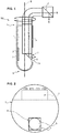
- the figure 1 is a sectional view of an embodiment of a device 100 for sampling biological tissue according to the invention.
- the device 100 comprises a rod 1 which extends along a longitudinal axis X between a proximal end 1a and a distal end 1b.
- proximal refers to the side closest to the hand of the practitioner and “distal” the farthest side intended to come into contact with the tissues.
- the rod 1 is made of a biocompatible material.
- the rod 1 can thus be made of stainless steel, or of a plastic material, such as PEEK which has, compared to stainless steel, to be compatible with MRI.
- the diameter of the rod is typically between 500 ⁇ m and 2000 ⁇ m, preferably between 800 ⁇ m and 1200 ⁇ m.
- a diameter of 1200 microns allows a correct insertion into an existing guide tube.
- the cross section of the rod 1 decreases between its proximal end and its distal end.
- the diameter D2 of the distal end is smaller than the diameter D1 of the proximal end.
- the diameter (or diagonal when the section is not circular) of the distal end is three times smaller than the diameter (or diagonal) of the proximal end. This allows a better grip of the rod by an operator, at the proximal end.
- the rod 1 carries a capture surface 2 which is intended to be applied against a biological tissue at which it is desired to perform a sampling.
- the capture surface 2 is generally a flat surface of rectangular outline, although it is not limited to this single form.
- the length of the capture surface is preferably arranged parallel to the longitudinal axis.
- the rod 1 may have a flattened at the periphery of the rod and on which the capture surface is secured, for example by gluing or by any other means.
- the connection of the capture surface vis-à-vis the rod may be removable or not.
- the flat is advantageously designed so that when the capture surface 2 is assembled on the rod 1, it is inscribed in the circular section of the rod and has no protrusion relative to the peripheral surface of the rod.
- the capture surface may be micro-structured so as to have protuberances for removing a biological tissue by micro-abrasion.
- said protuberances may consist of hexagonal pillars of 50 ⁇ m in height and 80 ⁇ m in diameter.
- the capture surface may be the surface of a nanoporous material.
- Silicon is frequently used as a capture surface material, regardless of the embodiment considered.
- the capture surface 2 may be coated with a functionalization layer promoting the grafting of analytes of interest.
- analyte refers to a chemical or biological species, in particular a protein or a cell.
- the functionalization layer can in particular be anionic.
- the capture surface 2 is located in a distal region of the rod 1.
- the rod 1 comprises an observation window 3 and a housing 4 extending in the rod from the proximal end 1a to said observation window.
- said housing 4 is intended to receive a bundle of optical fibers.
- window is meant in the present text a surface adapted to transmit the visible light between the external environment and the housing 4. Said window is obtained by making an opening between the outer surface of the rod and the housing 4.
- the window may optionally be materialized by a material transparent to visible light, this material may be organic (such as plexiglass) or inorganic (such as glass). However, the presence of such a material is not essential and the window can simply consist of a free space between the outer surface of the rod 1 and the housing 4.
- the housing 4 may consist of a bore made in the thickness of the rod.
- the housing 4 may consist of a groove formed in the outer surface of the rod 1, which is generally easier to achieve by machining.
- Said groove may have for example a square or rectangular section.
- the dimensions of said groove are adapted to those of the optical fiber bundle, so as to allow insertion of said bundle in said groove.
- the optical fiber bundle is removably arranged in the housing; it is for example retained by clamping in the housing 4.
- the beam may be inserted partially into the groove, that is to say a portion of the beam extends beyond the walls of the groove; alternatively, the beam is fully housed in the groove, its outer surface not exceeding the envelope defined by the walls of the groove.
- the space left free in the groove around the bundle can be filled by means of a biocompatible polymer applied in the liquid state and then hardened to form a confinement of the bundle. fiber bundle.
- said polymer further ensures a continuity of the outer surface of the rod to maintain its circular section.
- Said polymer is preferably an alginate, which is biocompatible and allows a reversible filling of the groove. Indeed, this alginate can then be dissolved in a bath of a suitable solvent, which makes it possible to remove the optical fiber bundle from the groove.
- the optical fiber bundle 5 advantageously comprises of the order of 3,000 optical fibers arranged in a circular section of beam of 0.3 mm in diameter.
- a beam is the one equipping the endoscope distributed by Mauna Kea Technologies under the reference CellVolo TM.
- the optical fibers are chosen to guide any wavelength for spectral characterization of biological tissues.
- the optical fibers must guide a wavelength range between ultraviolet and infrared, the latter having a much better penetration into the tissues.
- the beam 5 has a proximal end which is connected to an excitation and detection system, and a distal end which, when the beam is in its position of use in the rod 1, is arranged in the vicinity of the window of observation 3.
- the device 100 further comprises a return optical system 6 adapted to perform an optical coupling between the distal end of the beam and the observation window.
- said system 6 is arranged in the vicinity of the window 3.
- the optical coupling system may be integral with the rod (it may for example be formed of a prism glued to the distal end of the groove forming the housing 4, vis-à-vis the observation window 3) or the fiber bundle, in which case it is attached to the distal end of this beam.
- the optical coupling system is constituted by the end of the beam which is bevelled, the angle of the bevel being of the order of 40 to 50 °, preferably 45 °.
- the end of the beam forms an inclined plane; thus, each fiber of the beam is able to collect a light signal whose angle of incidence is inclined relative to the longitudinal axis of the beam.
- the optical redirection system is a reflective plate, oriented approximately 40 to 50 °, preferably 45 °, with respect to the longitudinal axis X.
- Said reflecting plate may belong to a prism, said prism being integral with the distal end of the optical fiber bundle, for example by crimping, gluing or by any other means.
- the prism typically has a square section whose length is equal to the diameter of the optical fiber bundle.
- the optical redirection system is configured to deflect the light emitted by the fiber bundle in a direction substantially orthogonal to the longitudinal axis X.
- the beam is able to collect, by its distal end, a light whose angle of incidence is orthogonal to the longitudinal axis X.
- the device 100 advantageously comprises a guide tube 7 inside which the rod 1 can slide.
- the guide tube comprises a lateral opening 70 so that when the rod is inserted into the tube, the opening 70 is opposite the portion of the rod which carries the capture surface and in which the opening is formed. observation window 3.
- the rod 1 is then free in translation and in rotation in the guide tube 7. This makes it possible to place, alternatively, the window 3 or the capture surface 2 facing the opening 70, as detailed in FIG. example described below.
- the guide tube 7 has the function of protect the stem and the capture surface, which can slide in the tube without being in contact with the tissues.
- the guide tube is made of a biocompatible material such as stainless steel.
- the inside diameter of the guide tube is typically between 1000 and 3000 ⁇ m, for example 1200 ⁇ m.
- the shape of the guide tube can be adapted accordingly.
- the opening of the guide tube, at its proximal end is wider than at its distal end.
- the outer geometry of the guide tube may also be discontinuous, the diameter (or diagonal in the case of a non-circular section) external to the proximal end being greater than the diameter (or diagonal) at the distal end.
- the figure 2 is a front view of the proximal end of the rod 1.
- the housing 4 is in this case a groove of rectangular section in which the optical fiber bundle 5 is completely contained.
- a prism 6 of fixed square base of the beam is arranged at the distal end of the groove, vis-à-vis the observation window (not shown here).
- Diametrically opposed to the groove 4 is arranged a flat bearing the capture surface 2, which is here micro-structured by means of projecting studs.
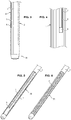
- the figure 3 is a side view of the rod, the housing 4 being a groove diametrically opposed to the capture surface 2.
- the figure 4 is a view of the distal end of the groove, which contains the beam 5 and a return optical system 6 arranged at the end of the beam.
- the excitation and detection system typically comprises a light source L (for example a laser) and a photodetector D (preferably a matrix photodetector).
- the light source emits light at an excitation wavelength.
- the photodetector is arranged to detect light at an emission wavelength, the latter being produced in particular by a biological tissue in response to the excitation light.
- the proximal end of the beam, the light source and the photodetector are advantageously coupled by a coupling optical system C, for example a dichroic mirror.
- the photodetector is preferably coupled to a filter, for example an interference filter, whose bandwidth is centered on the fluorescence wavelength (emission wavelength).
- a filter for example an interference filter, whose bandwidth is centered on the fluorescence wavelength (emission wavelength).
- This filter can be arranged on the dichroic mirror, or between the latter and the photodetector.
- the rod 1 is arranged in the guide tube 7 so that the observation window is opposite the opening 70 (cf. figure 5 ).
- the optical fibers collect the excitation light signal emitted by the light source L which is coupled to the proximal end of the beam to the distal end of the beam.
- the signal is deflected by the optical feedback system 6 and transmitted to the external environment of the tube through the observation window 3.
- the signal comes to excite fluorescent markers that have previously been injected to the patient who must undergo the sampling. , or endogenous fluorescent markers, naturally present in biological tissues.
- Said markers then emit a fluorescence signal, which is transmitted through the observation window 3, deflected by the optical redirection system 6 and led by the optical fibers to the photodetector D through the optical coupling system C, in the opposite direction to that of the excitation signal.
- the photodetector is adapted to detect a fluorescence signal emitted by the tissues and therefore indicates the presence or absence of the tissues of interest, the latter generating a fluorescence signal detectable by the photodetector D.
- the practitioner brings the capture surface 2 opposite the opening 70 to put it in contact with the tissues (cf. figure 6 ).
- the observation window 3 is located at the same longitudinal position of the rod as the capture surface but angularly offset.
- This angular offset is for example 180 ° (the capture surface and the observation window being diametrically opposed) but any other angle can be chosen.
- the device comprises an angular indexing system which allows it to easily position either the observation window 3 or the capture surface 2 vis-à-vis the opening 70 of the guide tube 7.
- the practitioner immobilizes the guide tube 7 and merely rotate the rod 1 to bring the capture surface 2. It is thus certain to perform the sampling in the same region as the one he observed and selected.
Claims (13)
- Vorrichtung (100) zur Probenahme von biologischem Gewebe, umfassend:- einen Stab (1), der sich entlang einer Längsachse (X) zwischen einem proximalen Ende (1a) und einem distalen Ende (1b) erstreckt,- eine vom Stab (1) getragene Auffangfläche (2), die dazu bestimmt ist, gegen ein biologisches Gewebe aufgebracht zu werden,- ein für sichtbares Licht transparentes Beobachtungsfenster (3), das in der Außenfläche des Stabes (1) gestaltet ist,- ein Gehäuse (4), das sich im Stab parallel zur Längsachse vom proximalen Ende (1a) bis zum Beobachtungsfenster (3) erstreckt, wobei das Gehäuse geeignet ist, ein optisches Faserbündel aufzunehmen,wobei die Vorrichtung (100) dadurch gekennzeichnet ist, dass die Auffangfläche nanoporös ist oder Vorsprünge aufweist, die geeignet sind, ein biologisches Gewebe durch Mikroabrieb zu entnehmen, und dass das Gehäuse (4) für das optische Faserbündel eine Nut aufweist, die in der Außenfläche des Stabes gestaltet ist.
- Vorrichtung nach Anspruch 1, wobei das Beobachtungsfenster (3) und die Auffangfläche (2) im gleichen Abstand vom distalen Ende des Stabes und im Winkelabstand angeordnet sind.
- Vorrichtung nach einem der Ansprüche 1 bis 2, umfassend:- ein optisches Faserbündel (5), das im Gehäuse (4) des Stabes so angeordnet ist, dass ein distales Ende des Bündels in der Nähe des Beobachtungsfensters (3) gestaltet ist, und- ein optisches Umlenksystem (6), das geeignet ist, eine optische Kopplung zwischen dem distalen Ende des Bündels und dem Beobachtungsfenster durchzuführen.
- Vorrichtung nach Anspruch 3, wobei das optische Umlenksystem eine reflektierende Lamelle umfasst, die in einem Winkel zwischen 40 ° und 50 ° zur Längsachse (X) des Stabes ausgerichtet ist.
- Vorrichtung nach Anspruch 4, wobei die reflektierende Lamelle Teil eines Prismas ist.
- Vorrichtung nach Anspruch 5, wobei das Prisma, das die reflektierende Lamelle umfasst, fest mit dem distalen Ende des optischen Faserbündels verbunden ist.
- Vorrichtung nach Anspruch 3, wobei das optische Umlenksystem aus einem abgeschrägten distalen Ende der das Bündel bildenden optischen Fasern besteht.
- Vorrichtung nach einem der Ansprüche 1 bis 7, ferner umfassend ein Führungsrohr (7), in dem der Stab (1) verschiebbar ist, wobei das Führungsrohr eine seitliche Öffnung (70) umfasst, die so gestaltet ist, dass, wenn der Stab in das Führungsrohr eingeführt wird, die Auffangfläche und das Beobachtungsfenster der seitlichen Öffnung (70) entsprechend der jeweiligen Winkelausrichtung des Führungsrohrs und des Stabes zugewandt sind.
- Vorrichtung nach dem vorstehenden Anspruch, ferner umfassend ein Winkelindexsystem zum Positionieren entweder der Auffangfläche (2) oder des Beobachtungslichts (3) gegenüber der seitlichen Öffnung (70) des Führungsrohrs (7).
- Vorrichtung nach einem der Ansprüche 1 bis 9, wobei sich die Auffangfläche in einem distalen Bereich des Stabes (1) befindet.
- Vorrichtung nach einem der Ansprüche 1 bis 10, wobei die Auffangfläche mit einer Funktionalisierungsschicht versehen ist.
- Vorrichtung nach einem der Ansprüche 1 bis 11, wobei der Stab (1) aus Edelstahl oder aus PEEK besteht.
- Vorrichtung nach einem der Ansprüche 1 bis 12, wobei der Stab (1) einen sich verjüngenden Abschnitt von seinem proximalen Ende (1a) zu seinem distalen Ende (1b) aufweist.
Applications Claiming Priority (1)
| Application Number | Priority Date | Filing Date | Title |
|---|---|---|---|
| FR1363695A FR3015882B1 (fr) | 2013-12-30 | 2013-12-30 | Dispositif de prelevement d'un tissu biologique |
Publications (2)
| Publication Number | Publication Date |
|---|---|
| EP2888990A1 EP2888990A1 (de) | 2015-07-01 |
| EP2888990B1 true EP2888990B1 (de) | 2018-11-28 |
Family
ID=50473497
Family Applications (1)
| Application Number | Title | Priority Date | Filing Date |
|---|---|---|---|
| EP14200532.1A Active EP2888990B1 (de) | 2013-12-30 | 2014-12-30 | Vorrichtung zur Entnahme eines biologischen Gewebes |
Country Status (3)
| Country | Link |
|---|---|
| US (1) | US10213190B2 (de) |
| EP (1) | EP2888990B1 (de) |
| FR (1) | FR3015882B1 (de) |
Family Cites Families (17)
| Publication number | Priority date | Publication date | Assignee | Title |
|---|---|---|---|---|
| US3556085A (en) * | 1968-02-26 | 1971-01-19 | Olympus Optical Co | Optical viewing instrument |
| US3945375A (en) * | 1972-04-04 | 1976-03-23 | Surgical Design Corporation | Rotatable surgical instrument |
| DK131542C (da) * | 1974-02-06 | 1976-02-09 | Akad Tekn Videnskaber | Kirurgisk instrument til udtagning af biologiske prover |
| US4566438A (en) * | 1984-10-05 | 1986-01-28 | Liese Grover J | Fiber-optic stylet for needle tip localization |
| US5280788A (en) * | 1991-02-26 | 1994-01-25 | Massachusetts Institute Of Technology | Devices and methods for optical diagnosis of tissue |
| US6564087B1 (en) * | 1991-04-29 | 2003-05-13 | Massachusetts Institute Of Technology | Fiber optic needle probes for optical coherence tomography imaging |
| WO1995005112A1 (en) * | 1993-08-18 | 1995-02-23 | Vista Medical Technologies | Optical surgical device |
| WO1999053841A1 (en) * | 1998-04-23 | 1999-10-28 | Cook Urological, Inc. | Endocervical and exocervical cell collection device |
| US6689142B1 (en) * | 1999-04-26 | 2004-02-10 | Scimed Life Systems, Inc. | Apparatus and methods for guiding a needle |
| WO2006090220A2 (en) * | 2005-01-14 | 2006-08-31 | Institut National De La Sante Et De La Recherche Medicale | Method and apparatus for taking a sample of a target tissue or another body structure |
| FR2881339B1 (fr) * | 2005-02-02 | 2009-07-10 | Commissariat Energie Atomique | Dispositif de prelevement moleculaire par contact |
| WO2009000078A1 (en) * | 2007-06-25 | 2008-12-31 | Led Medical Diagnostics, Inc. | Methods, systems and apparatus relating to colposcopic-type viewing extension devices |
| US8369915B2 (en) * | 2009-11-06 | 2013-02-05 | Wisconsin Alumni Research Foundation | Integrated miniaturized fiber optic probe |
| US8911433B2 (en) * | 2009-11-18 | 2014-12-16 | Boston Scientific Scimed, Inc. | Methods and apparatus related to a distal end of a side-fire optical fiber having multiple capillary components |
| US8672929B2 (en) * | 2010-12-15 | 2014-03-18 | Ams Research Corporation | Laser probe tip |
| WO2013091090A1 (en) * | 2011-12-22 | 2013-06-27 | University Health Network | Biopsy device with integrated optical spectroscopy guidance |
| FR2985164B1 (fr) * | 2011-12-29 | 2015-02-27 | Commissariat Energie Atomique | Dispositif et procede de prelevement et analyse d'especes biologiques ou biochimiques. |
-
2013
- 2013-12-30 FR FR1363695A patent/FR3015882B1/fr active Active
-
2014
- 2014-12-30 EP EP14200532.1A patent/EP2888990B1/de active Active
- 2014-12-30 US US14/585,361 patent/US10213190B2/en active Active
Non-Patent Citations (1)
| Title |
|---|
| None * |
Also Published As
| Publication number | Publication date |
|---|---|
| FR3015882B1 (fr) | 2020-01-17 |
| EP2888990A1 (de) | 2015-07-01 |
| US20150182207A1 (en) | 2015-07-02 |
| FR3015882A1 (fr) | 2015-07-03 |
| US10213190B2 (en) | 2019-02-26 |
Similar Documents
| Publication | Publication Date | Title |
|---|---|---|
| EP2456354B1 (de) | Spitze fasernadelsonde für optische tiefendiagnose von tumoren mittels endogener fluoreszenz | |
| Latka et al. | Fiber optic probes for linear and nonlinear Raman applications–Current trends and future development | |
| EP3393368B1 (de) | Vorrichtung zum verarbeiten von 3d-biopsiegewebe | |
| EP2309249B1 (de) | Vorrichtung und Verfahren zur gestreuten Erregung in der Bildgebung | |
| JP5108649B2 (ja) | 対物レンズ用アダプタ | |
| US11064982B2 (en) | Systems, devices and methods for tissue removal and analysis | |
| EP2773259B1 (de) | Ramanspektroskopiesonde | |
| US20100234684A1 (en) | Multifunctional endoscopic device and methods employing said device | |
| US10463349B2 (en) | Device for obtaining 3D biopsy | |
| CA3051489C (en) | Needle assembly and system for collection and optical interrogation of a biological sample | |
| EP2888990B1 (de) | Vorrichtung zur Entnahme eines biologischen Gewebes | |
| EP2477554B1 (de) | Chirurgisches instrument für molekulare probennahme | |
| EP2228003A1 (de) | Multifunktionelle Endoskopievorrichtung und Verfahren zur Anwendung der Vorrichtung | |
| WO2022161816A1 (fr) | Dispositifs pour l'analyse microscopique ex vivo d'echantillons et in vivo de la peau | |
| EP3465320B1 (de) | Vorrichtung und verfahren zur bereitstellung von beleuchtung für fluoreszenzmikroskopie mit interner totalreflexion | |
| US20200015684A1 (en) | Probe for optical spectroscopy | |
| WO2014096138A1 (fr) | Dispositif de conservation d'un echantillon biologique | |
| FR3034869A1 (fr) | Dispositif, kit et procede de calibration de fluorescence |
Legal Events
| Date | Code | Title | Description |
|---|---|---|---|
| PUAI | Public reference made under article 153(3) epc to a published international application that has entered the european phase |
Free format text: ORIGINAL CODE: 0009012 |
|
| 17P | Request for examination filed |
Effective date: 20141230 |
|
| AK | Designated contracting states |
Kind code of ref document: A1 Designated state(s): AL AT BE BG CH CY CZ DE DK EE ES FI FR GB GR HR HU IE IS IT LI LT LU LV MC MK MT NL NO PL PT RO RS SE SI SK SM TR |
|
| AX | Request for extension of the european patent |
Extension state: BA ME |
|
| R17P | Request for examination filed (corrected) |
Effective date: 20160104 |
|
| RBV | Designated contracting states (corrected) |
Designated state(s): AL AT BE BG CH CY CZ DE DK EE ES FI FR GB GR HR HU IE IS IT LI LT LU LV MC MK MT NL NO PL PT RO RS SE SI SK SM TR |
|
| GRAJ | Information related to disapproval of communication of intention to grant by the applicant or resumption of examination proceedings by the epo deleted |
Free format text: ORIGINAL CODE: EPIDOSDIGR1 |
|
| GRAP | Despatch of communication of intention to grant a patent |
Free format text: ORIGINAL CODE: EPIDOSNIGR1 |
|
| RAP1 | Party data changed (applicant data changed or rights of an application transferred) |
Owner name: UNIVERSITE GRENOBLE ALPES Owner name: CENTRE HOSPITALIER UNIVERSITAIRE GRENOBLE ALPES Owner name: COMMISSARIAT A L'ENERGIE ATOMIQUE ET AUX ENERGIES |
|
| GRAP | Despatch of communication of intention to grant a patent |
Free format text: ORIGINAL CODE: EPIDOSNIGR1 |
|
| INTG | Intention to grant announced |
Effective date: 20180827 |
|
| RAP1 | Party data changed (applicant data changed or rights of an application transferred) |
Owner name: CENTRE HOSPITALIER UNIVERSITAIRE GRENOBLE ALPES Owner name: UNIVERSITE GRENOBLE ALPES Owner name: COMMISSARIAT A L'ENERGIE ATOMIQUE ET AUX ENERGIES |
|
| RIN1 | Information on inventor provided before grant (corrected) |
Inventor name: MOMBRUN, ADRIEN Inventor name: BOUAMRANI, ALI Inventor name: BERGER, FRANCOIS Inventor name: DREYFUS, MATTHIEU |
|
| GRAS | Grant fee paid |
Free format text: ORIGINAL CODE: EPIDOSNIGR3 |
|
| GRAA | (expected) grant |
Free format text: ORIGINAL CODE: 0009210 |
|
| AK | Designated contracting states |
Kind code of ref document: B1 Designated state(s): AL AT BE BG CH CY CZ DE DK EE ES FI FR GB GR HR HU IE IS IT LI LT LU LV MC MK MT NL NO PL PT RO RS SE SI SK SM TR |
|
| REG | Reference to a national code |
Ref country code: CH Ref legal event code: EP |
|
| REG | Reference to a national code |
Ref country code: AT Ref legal event code: REF Ref document number: 1069256 Country of ref document: AT Kind code of ref document: T Effective date: 20181215 |
|
| REG | Reference to a national code |
Ref country code: DE Ref legal event code: R096 Ref document number: 602014036860 Country of ref document: DE |
|
| REG | Reference to a national code |
Ref country code: IE Ref legal event code: FG4D Free format text: LANGUAGE OF EP DOCUMENT: FRENCH |
|
| REG | Reference to a national code |
Ref country code: NL Ref legal event code: MP Effective date: 20181128 |
|
| REG | Reference to a national code |
Ref country code: LT Ref legal event code: MG4D |
|
| REG | Reference to a national code |
Ref country code: AT Ref legal event code: MK05 Ref document number: 1069256 Country of ref document: AT Kind code of ref document: T Effective date: 20181128 |
|
| PG25 | Lapsed in a contracting state [announced via postgrant information from national office to epo] |
Ref country code: FI Free format text: LAPSE BECAUSE OF FAILURE TO SUBMIT A TRANSLATION OF THE DESCRIPTION OR TO PAY THE FEE WITHIN THE PRESCRIBED TIME-LIMIT Effective date: 20181128 Ref country code: IS Free format text: LAPSE BECAUSE OF FAILURE TO SUBMIT A TRANSLATION OF THE DESCRIPTION OR TO PAY THE FEE WITHIN THE PRESCRIBED TIME-LIMIT Effective date: 20190328 Ref country code: NO Free format text: LAPSE BECAUSE OF FAILURE TO SUBMIT A TRANSLATION OF THE DESCRIPTION OR TO PAY THE FEE WITHIN THE PRESCRIBED TIME-LIMIT Effective date: 20190228 Ref country code: AT Free format text: LAPSE BECAUSE OF FAILURE TO SUBMIT A TRANSLATION OF THE DESCRIPTION OR TO PAY THE FEE WITHIN THE PRESCRIBED TIME-LIMIT Effective date: 20181128 Ref country code: LV Free format text: LAPSE BECAUSE OF FAILURE TO SUBMIT A TRANSLATION OF THE DESCRIPTION OR TO PAY THE FEE WITHIN THE PRESCRIBED TIME-LIMIT Effective date: 20181128 Ref country code: ES Free format text: LAPSE BECAUSE OF FAILURE TO SUBMIT A TRANSLATION OF THE DESCRIPTION OR TO PAY THE FEE WITHIN THE PRESCRIBED TIME-LIMIT Effective date: 20181128 Ref country code: LT Free format text: LAPSE BECAUSE OF FAILURE TO SUBMIT A TRANSLATION OF THE DESCRIPTION OR TO PAY THE FEE WITHIN THE PRESCRIBED TIME-LIMIT Effective date: 20181128 Ref country code: BG Free format text: LAPSE BECAUSE OF FAILURE TO SUBMIT A TRANSLATION OF THE DESCRIPTION OR TO PAY THE FEE WITHIN THE PRESCRIBED TIME-LIMIT Effective date: 20190228 Ref country code: HR Free format text: LAPSE BECAUSE OF FAILURE TO SUBMIT A TRANSLATION OF THE DESCRIPTION OR TO PAY THE FEE WITHIN THE PRESCRIBED TIME-LIMIT Effective date: 20181128 |
|
| PG25 | Lapsed in a contracting state [announced via postgrant information from national office to epo] |
Ref country code: AL Free format text: LAPSE BECAUSE OF FAILURE TO SUBMIT A TRANSLATION OF THE DESCRIPTION OR TO PAY THE FEE WITHIN THE PRESCRIBED TIME-LIMIT Effective date: 20181128 Ref country code: PT Free format text: LAPSE BECAUSE OF FAILURE TO SUBMIT A TRANSLATION OF THE DESCRIPTION OR TO PAY THE FEE WITHIN THE PRESCRIBED TIME-LIMIT Effective date: 20190328 Ref country code: SE Free format text: LAPSE BECAUSE OF FAILURE TO SUBMIT A TRANSLATION OF THE DESCRIPTION OR TO PAY THE FEE WITHIN THE PRESCRIBED TIME-LIMIT Effective date: 20181128 Ref country code: RS Free format text: LAPSE BECAUSE OF FAILURE TO SUBMIT A TRANSLATION OF THE DESCRIPTION OR TO PAY THE FEE WITHIN THE PRESCRIBED TIME-LIMIT Effective date: 20181128 Ref country code: GR Free format text: LAPSE BECAUSE OF FAILURE TO SUBMIT A TRANSLATION OF THE DESCRIPTION OR TO PAY THE FEE WITHIN THE PRESCRIBED TIME-LIMIT Effective date: 20190301 |
|
| PG25 | Lapsed in a contracting state [announced via postgrant information from national office to epo] |
Ref country code: NL Free format text: LAPSE BECAUSE OF FAILURE TO SUBMIT A TRANSLATION OF THE DESCRIPTION OR TO PAY THE FEE WITHIN THE PRESCRIBED TIME-LIMIT Effective date: 20181128 |
|
| PG25 | Lapsed in a contracting state [announced via postgrant information from national office to epo] |
Ref country code: CZ Free format text: LAPSE BECAUSE OF FAILURE TO SUBMIT A TRANSLATION OF THE DESCRIPTION OR TO PAY THE FEE WITHIN THE PRESCRIBED TIME-LIMIT Effective date: 20181128 Ref country code: DK Free format text: LAPSE BECAUSE OF FAILURE TO SUBMIT A TRANSLATION OF THE DESCRIPTION OR TO PAY THE FEE WITHIN THE PRESCRIBED TIME-LIMIT Effective date: 20181128 Ref country code: PL Free format text: LAPSE BECAUSE OF FAILURE TO SUBMIT A TRANSLATION OF THE DESCRIPTION OR TO PAY THE FEE WITHIN THE PRESCRIBED TIME-LIMIT Effective date: 20181128 Ref country code: IT Free format text: LAPSE BECAUSE OF FAILURE TO SUBMIT A TRANSLATION OF THE DESCRIPTION OR TO PAY THE FEE WITHIN THE PRESCRIBED TIME-LIMIT Effective date: 20181128 |
|
| REG | Reference to a national code |
Ref country code: CH Ref legal event code: PL |
|
| REG | Reference to a national code |
Ref country code: DE Ref legal event code: R097 Ref document number: 602014036860 Country of ref document: DE |
|
| PG25 | Lapsed in a contracting state [announced via postgrant information from national office to epo] |
Ref country code: EE Free format text: LAPSE BECAUSE OF FAILURE TO SUBMIT A TRANSLATION OF THE DESCRIPTION OR TO PAY THE FEE WITHIN THE PRESCRIBED TIME-LIMIT Effective date: 20181128 Ref country code: SM Free format text: LAPSE BECAUSE OF FAILURE TO SUBMIT A TRANSLATION OF THE DESCRIPTION OR TO PAY THE FEE WITHIN THE PRESCRIBED TIME-LIMIT Effective date: 20181128 Ref country code: RO Free format text: LAPSE BECAUSE OF FAILURE TO SUBMIT A TRANSLATION OF THE DESCRIPTION OR TO PAY THE FEE WITHIN THE PRESCRIBED TIME-LIMIT Effective date: 20181128 Ref country code: LU Free format text: LAPSE BECAUSE OF NON-PAYMENT OF DUE FEES Effective date: 20181230 Ref country code: SK Free format text: LAPSE BECAUSE OF FAILURE TO SUBMIT A TRANSLATION OF THE DESCRIPTION OR TO PAY THE FEE WITHIN THE PRESCRIBED TIME-LIMIT Effective date: 20181128 Ref country code: MC Free format text: LAPSE BECAUSE OF FAILURE TO SUBMIT A TRANSLATION OF THE DESCRIPTION OR TO PAY THE FEE WITHIN THE PRESCRIBED TIME-LIMIT Effective date: 20181128 |
|
| REG | Reference to a national code |
Ref country code: BE Ref legal event code: MM Effective date: 20181231 Ref country code: IE Ref legal event code: MM4A |
|
| PLBE | No opposition filed within time limit |
Free format text: ORIGINAL CODE: 0009261 |
|
| STAA | Information on the status of an ep patent application or granted ep patent |
Free format text: STATUS: NO OPPOSITION FILED WITHIN TIME LIMIT |
|
| PG25 | Lapsed in a contracting state [announced via postgrant information from national office to epo] |
Ref country code: IE Free format text: LAPSE BECAUSE OF NON-PAYMENT OF DUE FEES Effective date: 20181230 Ref country code: SI Free format text: LAPSE BECAUSE OF FAILURE TO SUBMIT A TRANSLATION OF THE DESCRIPTION OR TO PAY THE FEE WITHIN THE PRESCRIBED TIME-LIMIT Effective date: 20181128 |
|
| 26N | No opposition filed |
Effective date: 20190829 |
|
| PG25 | Lapsed in a contracting state [announced via postgrant information from national office to epo] |
Ref country code: BE Free format text: LAPSE BECAUSE OF NON-PAYMENT OF DUE FEES Effective date: 20181231 |
|
| PG25 | Lapsed in a contracting state [announced via postgrant information from national office to epo] |
Ref country code: CH Free format text: LAPSE BECAUSE OF NON-PAYMENT OF DUE FEES Effective date: 20181231 Ref country code: LI Free format text: LAPSE BECAUSE OF NON-PAYMENT OF DUE FEES Effective date: 20181231 |
|
| PG25 | Lapsed in a contracting state [announced via postgrant information from national office to epo] |
Ref country code: MT Free format text: LAPSE BECAUSE OF FAILURE TO SUBMIT A TRANSLATION OF THE DESCRIPTION OR TO PAY THE FEE WITHIN THE PRESCRIBED TIME-LIMIT Effective date: 20181128 |
|
| PG25 | Lapsed in a contracting state [announced via postgrant information from national office to epo] |
Ref country code: TR Free format text: LAPSE BECAUSE OF FAILURE TO SUBMIT A TRANSLATION OF THE DESCRIPTION OR TO PAY THE FEE WITHIN THE PRESCRIBED TIME-LIMIT Effective date: 20181128 |
|
| PG25 | Lapsed in a contracting state [announced via postgrant information from national office to epo] |
Ref country code: HU Free format text: LAPSE BECAUSE OF FAILURE TO SUBMIT A TRANSLATION OF THE DESCRIPTION OR TO PAY THE FEE WITHIN THE PRESCRIBED TIME-LIMIT; INVALID AB INITIO Effective date: 20141230 Ref country code: MK Free format text: LAPSE BECAUSE OF NON-PAYMENT OF DUE FEES Effective date: 20181128 Ref country code: CY Free format text: LAPSE BECAUSE OF FAILURE TO SUBMIT A TRANSLATION OF THE DESCRIPTION OR TO PAY THE FEE WITHIN THE PRESCRIBED TIME-LIMIT Effective date: 20181128 |
|
| PGFP | Annual fee paid to national office [announced via postgrant information from national office to epo] |
Ref country code: GB Payment date: 20231221 Year of fee payment: 10 |
|
| PGFP | Annual fee paid to national office [announced via postgrant information from national office to epo] |
Ref country code: FR Payment date: 20231220 Year of fee payment: 10 Ref country code: DE Payment date: 20231208 Year of fee payment: 10 |