EP2888990B1 - Device for sampling a biological tissue - Google Patents
Device for sampling a biological tissue Download PDFInfo
- Publication number
- EP2888990B1 EP2888990B1 EP14200532.1A EP14200532A EP2888990B1 EP 2888990 B1 EP2888990 B1 EP 2888990B1 EP 14200532 A EP14200532 A EP 14200532A EP 2888990 B1 EP2888990 B1 EP 2888990B1
- Authority
- EP
- European Patent Office
- Prior art keywords
- rod
- distal end
- capture surface
- observation window
- bundle
- Prior art date
- Legal status (The legal status is an assumption and is not a legal conclusion. Google has not performed a legal analysis and makes no representation as to the accuracy of the status listed.)
- Active
Links
- 238000005070 sampling Methods 0.000 title claims description 20
- 230000003287 optical effect Effects 0.000 claims description 24
- 230000008878 coupling Effects 0.000 claims description 7
- 238000010168 coupling process Methods 0.000 claims description 7
- 238000005859 coupling reaction Methods 0.000 claims description 7
- 229910001220 stainless steel Inorganic materials 0.000 claims description 5
- 239000010935 stainless steel Substances 0.000 claims description 5
- 238000007306 functionalization reaction Methods 0.000 claims description 4
- 239000004696 Poly ether ether ketone Substances 0.000 claims description 3
- JUPQTSLXMOCDHR-UHFFFAOYSA-N benzene-1,4-diol;bis(4-fluorophenyl)methanone Chemical compound OC1=CC=C(O)C=C1.C1=CC(F)=CC=C1C(=O)C1=CC=C(F)C=C1 JUPQTSLXMOCDHR-UHFFFAOYSA-N 0.000 claims description 3
- 230000003247 decreasing effect Effects 0.000 claims description 3
- 229920002530 polyetherether ketone Polymers 0.000 claims description 3
- 238000005299 abrasion Methods 0.000 claims description 2
- 210000001519 tissue Anatomy 0.000 description 28
- 239000013307 optical fiber Substances 0.000 description 21
- 230000005284 excitation Effects 0.000 description 6
- 239000000835 fiber Substances 0.000 description 5
- 238000002595 magnetic resonance imaging Methods 0.000 description 5
- 239000000463 material Substances 0.000 description 5
- 210000000056 organ Anatomy 0.000 description 5
- FHVDTGUDJYJELY-UHFFFAOYSA-N 6-{[2-carboxy-4,5-dihydroxy-6-(phosphanyloxy)oxan-3-yl]oxy}-4,5-dihydroxy-3-phosphanyloxane-2-carboxylic acid Chemical compound O1C(C(O)=O)C(P)C(O)C(O)C1OC1C(C(O)=O)OC(OP)C(O)C1O FHVDTGUDJYJELY-UHFFFAOYSA-N 0.000 description 2
- 206010028980 Neoplasm Diseases 0.000 description 2
- 238000004026 adhesive bonding Methods 0.000 description 2
- 229940072056 alginate Drugs 0.000 description 2
- 235000010443 alginic acid Nutrition 0.000 description 2
- 229920000615 alginic acid Polymers 0.000 description 2
- 239000000560 biocompatible material Substances 0.000 description 2
- 238000001574 biopsy Methods 0.000 description 2
- 238000001514 detection method Methods 0.000 description 2
- 238000005286 illumination Methods 0.000 description 2
- 238000003384 imaging method Methods 0.000 description 2
- 238000003780 insertion Methods 0.000 description 2
- 230000037431 insertion Effects 0.000 description 2
- 229920002521 macromolecule Polymers 0.000 description 2
- 239000007783 nanoporous material Substances 0.000 description 2
- 229920000642 polymer Polymers 0.000 description 2
- 229910052710 silicon Inorganic materials 0.000 description 2
- 239000010703 silicon Substances 0.000 description 2
- 208000003174 Brain Neoplasms Diseases 0.000 description 1
- VVQNEPGJFQJSBK-UHFFFAOYSA-N Methyl methacrylate Chemical compound COC(=O)C(C)=C VVQNEPGJFQJSBK-UHFFFAOYSA-N 0.000 description 1
- 229920005372 Plexiglas® Polymers 0.000 description 1
- 241001080024 Telles Species 0.000 description 1
- 208000027418 Wounds and injury Diseases 0.000 description 1
- 239000012491 analyte Substances 0.000 description 1
- 238000004458 analytical method Methods 0.000 description 1
- 210000003484 anatomy Anatomy 0.000 description 1
- 125000000129 anionic group Chemical group 0.000 description 1
- 229920000249 biocompatible polymer Polymers 0.000 description 1
- 238000012512 characterization method Methods 0.000 description 1
- 230000001149 cognitive effect Effects 0.000 description 1
- 238000002788 crimping Methods 0.000 description 1
- 230000006378 damage Effects 0.000 description 1
- 230000007423 decrease Effects 0.000 description 1
- 238000005516 engineering process Methods 0.000 description 1
- 230000002349 favourable effect Effects 0.000 description 1
- 239000011521 glass Substances 0.000 description 1
- 208000014674 injury Diseases 0.000 description 1
- 230000002427 irreversible effect Effects 0.000 description 1
- 230000003902 lesion Effects 0.000 description 1
- 239000007788 liquid Substances 0.000 description 1
- 238000003754 machining Methods 0.000 description 1
- 239000000696 magnetic material Substances 0.000 description 1
- 239000011159 matrix material Substances 0.000 description 1
- 210000000653 nervous system Anatomy 0.000 description 1
- 230000035515 penetration Effects 0.000 description 1
- 230000002093 peripheral effect Effects 0.000 description 1
- 229920003023 plastic Polymers 0.000 description 1
- 239000004033 plastic Substances 0.000 description 1
- 230000001737 promoting effect Effects 0.000 description 1
- 102000004169 proteins and genes Human genes 0.000 description 1
- 108090000623 proteins and genes Proteins 0.000 description 1
- 230000000717 retained effect Effects 0.000 description 1
- 230000002441 reversible effect Effects 0.000 description 1
- 239000002904 solvent Substances 0.000 description 1
- 241000894007 species Species 0.000 description 1
- 230000003595 spectral effect Effects 0.000 description 1
- 239000000126 substance Substances 0.000 description 1
- 238000001356 surgical procedure Methods 0.000 description 1
Images

Classifications
-
- A—HUMAN NECESSITIES
- A61—MEDICAL OR VETERINARY SCIENCE; HYGIENE
- A61B—DIAGNOSIS; SURGERY; IDENTIFICATION
- A61B10/00—Other methods or instruments for diagnosis, e.g. instruments for taking a cell sample, for biopsy, for vaccination diagnosis; Sex determination; Ovulation-period determination; Throat striking implements
- A61B10/02—Instruments for taking cell samples or for biopsy
- A61B10/04—Endoscopic instruments
-
- A—HUMAN NECESSITIES
- A61—MEDICAL OR VETERINARY SCIENCE; HYGIENE
- A61B—DIAGNOSIS; SURGERY; IDENTIFICATION
- A61B1/00—Instruments for performing medical examinations of the interior of cavities or tubes of the body by visual or photographical inspection, e.g. endoscopes; Illuminating arrangements therefor
- A61B1/00064—Constructional details of the endoscope body
- A61B1/00071—Insertion part of the endoscope body
- A61B1/0008—Insertion part of the endoscope body characterised by distal tip features
- A61B1/00087—Tools
-
- A—HUMAN NECESSITIES
- A61—MEDICAL OR VETERINARY SCIENCE; HYGIENE
- A61B—DIAGNOSIS; SURGERY; IDENTIFICATION
- A61B1/00—Instruments for performing medical examinations of the interior of cavities or tubes of the body by visual or photographical inspection, e.g. endoscopes; Illuminating arrangements therefor
- A61B1/00064—Constructional details of the endoscope body
- A61B1/00071—Insertion part of the endoscope body
- A61B1/0008—Insertion part of the endoscope body characterised by distal tip features
- A61B1/00096—Optical elements
-
- A—HUMAN NECESSITIES
- A61—MEDICAL OR VETERINARY SCIENCE; HYGIENE
- A61B—DIAGNOSIS; SURGERY; IDENTIFICATION
- A61B1/00—Instruments for performing medical examinations of the interior of cavities or tubes of the body by visual or photographical inspection, e.g. endoscopes; Illuminating arrangements therefor
- A61B1/00147—Holding or positioning arrangements
- A61B1/00154—Holding or positioning arrangements using guiding arrangements for insertion
-
- A—HUMAN NECESSITIES
- A61—MEDICAL OR VETERINARY SCIENCE; HYGIENE
- A61B—DIAGNOSIS; SURGERY; IDENTIFICATION
- A61B1/00—Instruments for performing medical examinations of the interior of cavities or tubes of the body by visual or photographical inspection, e.g. endoscopes; Illuminating arrangements therefor
- A61B1/00163—Optical arrangements
- A61B1/00165—Optical arrangements with light-conductive means, e.g. fibre optics
- A61B1/00167—Details of optical fibre bundles, e.g. shape or fibre distribution
-
- A—HUMAN NECESSITIES
- A61—MEDICAL OR VETERINARY SCIENCE; HYGIENE
- A61B—DIAGNOSIS; SURGERY; IDENTIFICATION
- A61B1/00—Instruments for performing medical examinations of the interior of cavities or tubes of the body by visual or photographical inspection, e.g. endoscopes; Illuminating arrangements therefor
- A61B1/00163—Optical arrangements
- A61B1/00174—Optical arrangements characterised by the viewing angles
- A61B1/00177—Optical arrangements characterised by the viewing angles for 90 degrees side-viewing
-
- A—HUMAN NECESSITIES
- A61—MEDICAL OR VETERINARY SCIENCE; HYGIENE
- A61B—DIAGNOSIS; SURGERY; IDENTIFICATION
- A61B1/00—Instruments for performing medical examinations of the interior of cavities or tubes of the body by visual or photographical inspection, e.g. endoscopes; Illuminating arrangements therefor
- A61B1/04—Instruments for performing medical examinations of the interior of cavities or tubes of the body by visual or photographical inspection, e.g. endoscopes; Illuminating arrangements therefor combined with photographic or television appliances
- A61B1/043—Instruments for performing medical examinations of the interior of cavities or tubes of the body by visual or photographical inspection, e.g. endoscopes; Illuminating arrangements therefor combined with photographic or television appliances for fluorescence imaging
-
- A—HUMAN NECESSITIES
- A61—MEDICAL OR VETERINARY SCIENCE; HYGIENE
- A61B—DIAGNOSIS; SURGERY; IDENTIFICATION
- A61B1/00—Instruments for performing medical examinations of the interior of cavities or tubes of the body by visual or photographical inspection, e.g. endoscopes; Illuminating arrangements therefor
- A61B1/06—Instruments for performing medical examinations of the interior of cavities or tubes of the body by visual or photographical inspection, e.g. endoscopes; Illuminating arrangements therefor with illuminating arrangements
- A61B1/0615—Instruments for performing medical examinations of the interior of cavities or tubes of the body by visual or photographical inspection, e.g. endoscopes; Illuminating arrangements therefor with illuminating arrangements for radial illumination
-
- A—HUMAN NECESSITIES
- A61—MEDICAL OR VETERINARY SCIENCE; HYGIENE
- A61B—DIAGNOSIS; SURGERY; IDENTIFICATION
- A61B10/00—Other methods or instruments for diagnosis, e.g. instruments for taking a cell sample, for biopsy, for vaccination diagnosis; Sex determination; Ovulation-period determination; Throat striking implements
- A61B10/0045—Devices for taking samples of body liquids
-
- A—HUMAN NECESSITIES
- A61—MEDICAL OR VETERINARY SCIENCE; HYGIENE
- A61B—DIAGNOSIS; SURGERY; IDENTIFICATION
- A61B10/00—Other methods or instruments for diagnosis, e.g. instruments for taking a cell sample, for biopsy, for vaccination diagnosis; Sex determination; Ovulation-period determination; Throat striking implements
- A61B10/02—Instruments for taking cell samples or for biopsy
-
- A—HUMAN NECESSITIES
- A61—MEDICAL OR VETERINARY SCIENCE; HYGIENE
- A61B—DIAGNOSIS; SURGERY; IDENTIFICATION
- A61B5/00—Measuring for diagnostic purposes; Identification of persons
- A61B5/0059—Measuring for diagnostic purposes; Identification of persons using light, e.g. diagnosis by transillumination, diascopy, fluorescence
- A61B5/0071—Measuring for diagnostic purposes; Identification of persons using light, e.g. diagnosis by transillumination, diascopy, fluorescence by measuring fluorescence emission
-
- A—HUMAN NECESSITIES
- A61—MEDICAL OR VETERINARY SCIENCE; HYGIENE
- A61B—DIAGNOSIS; SURGERY; IDENTIFICATION
- A61B5/00—Measuring for diagnostic purposes; Identification of persons
- A61B5/0059—Measuring for diagnostic purposes; Identification of persons using light, e.g. diagnosis by transillumination, diascopy, fluorescence
- A61B5/0082—Measuring for diagnostic purposes; Identification of persons using light, e.g. diagnosis by transillumination, diascopy, fluorescence adapted for particular medical purposes
- A61B5/0084—Measuring for diagnostic purposes; Identification of persons using light, e.g. diagnosis by transillumination, diascopy, fluorescence adapted for particular medical purposes for introduction into the body, e.g. by catheters
-
- A—HUMAN NECESSITIES
- A61—MEDICAL OR VETERINARY SCIENCE; HYGIENE
- A61B—DIAGNOSIS; SURGERY; IDENTIFICATION
- A61B10/00—Other methods or instruments for diagnosis, e.g. instruments for taking a cell sample, for biopsy, for vaccination diagnosis; Sex determination; Ovulation-period determination; Throat striking implements
- A61B10/02—Instruments for taking cell samples or for biopsy
- A61B2010/0216—Sampling brushes
-
- H—ELECTRICITY
- H01—ELECTRIC ELEMENTS
- H01L—SEMICONDUCTOR DEVICES NOT COVERED BY CLASS H10
- H01L2224/00—Indexing scheme for arrangements for connecting or disconnecting semiconductor or solid-state bodies and methods related thereto as covered by H01L24/00
- H01L2224/01—Means for bonding being attached to, or being formed on, the surface to be connected, e.g. chip-to-package, die-attach, "first-level" interconnects; Manufacturing methods related thereto
- H01L2224/02—Bonding areas; Manufacturing methods related thereto
- H01L2224/04—Structure, shape, material or disposition of the bonding areas prior to the connecting process
- H01L2224/05—Structure, shape, material or disposition of the bonding areas prior to the connecting process of an individual bonding area
- H01L2224/0554—External layer
- H01L2224/05599—Material
- H01L2224/056—Material with a principal constituent of the material being a metal or a metalloid, e.g. boron [B], silicon [Si], germanium [Ge], arsenic [As], antimony [Sb], tellurium [Te] and polonium [Po], and alloys thereof
- H01L2224/05617—Material with a principal constituent of the material being a metal or a metalloid, e.g. boron [B], silicon [Si], germanium [Ge], arsenic [As], antimony [Sb], tellurium [Te] and polonium [Po], and alloys thereof the principal constituent melting at a temperature of greater than or equal to 400°C and less than 950°C
- H01L2224/05624—Aluminium [Al] as principal constituent
Definitions
- the present invention relates to a device for sampling a biological tissue.
- WO 2006/082344 discloses a minimally invasive sampling device, which includes a stem and a capture surface carried by the stem, for application against a biological tissue.
- the document WO 2013/098703 discloses a similar device, wherein the capture surface comprises a nanoporous material, and in particular nanoporous silicon.
- the capture surface is precisely brought to the tumor in order to collect the cells and macromolecules of interest.
- MRI magnetic resonance imaging
- WO 2013/091090 discloses a biopsy device comprising a cannula which has a window provided with sharp edges to aspirate and then cut the sample to be taken.
- a bundle of fibers is arranged in the inner conduit of said cannula.
- An object of the invention is to design a minimally invasive biological tissue sampling device which makes it possible to locate with improved accuracy the location of the area in which the sample is taken without involving an external imaging system such as the MRI.
- observation window and the capture surface are arranged at the same distance from the distal end of the rod and angularly spaced apart.
- Said housing of the optical fiber bundle comprises a groove arranged in the outer surface of the rod.
- the optical return system comprises a reflecting plate oriented at an angle of between 40 and 50 ° with respect to the longitudinal axis of the rod.
- said reflecting plate is part of a prism.
- the prism comprising said reflecting plate is integral with the distal end of the optical fiber bundle.
- the optical return system consists of a beveled distal end of the optical fibers forming the beam.
- the device may further comprise a guide tube in which the rod is slidable, said guide tube comprising a lateral opening arranged so that when the rod is introduced into the guide tube the capture surface and the observation window come vis-à-vis said lateral opening according to the respective angular orientation of the guide tube and the rod.
- the capture surface is advantageously located in a distal region of the stem.
- the capture surface is coated with a functionalization layer.
- the rod is for example stainless steel or PEEK.
- the stem has a decreasing section from its proximal end towards its distal end.
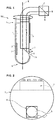
- the figure 1 is a sectional view of an embodiment of a device 100 for sampling biological tissue according to the invention.
- the device 100 comprises a rod 1 which extends along a longitudinal axis X between a proximal end 1a and a distal end 1b.
- proximal refers to the side closest to the hand of the practitioner and “distal” the farthest side intended to come into contact with the tissues.
- the rod 1 is made of a biocompatible material.
- the rod 1 can thus be made of stainless steel, or of a plastic material, such as PEEK which has, compared to stainless steel, to be compatible with MRI.
- the diameter of the rod is typically between 500 ⁇ m and 2000 ⁇ m, preferably between 800 ⁇ m and 1200 ⁇ m.
- a diameter of 1200 microns allows a correct insertion into an existing guide tube.
- the cross section of the rod 1 decreases between its proximal end and its distal end.
- the diameter D2 of the distal end is smaller than the diameter D1 of the proximal end.
- the diameter (or diagonal when the section is not circular) of the distal end is three times smaller than the diameter (or diagonal) of the proximal end. This allows a better grip of the rod by an operator, at the proximal end.
- the rod 1 carries a capture surface 2 which is intended to be applied against a biological tissue at which it is desired to perform a sampling.
- the capture surface 2 is generally a flat surface of rectangular outline, although it is not limited to this single form.
- the length of the capture surface is preferably arranged parallel to the longitudinal axis.
- the rod 1 may have a flattened at the periphery of the rod and on which the capture surface is secured, for example by gluing or by any other means.
- the connection of the capture surface vis-à-vis the rod may be removable or not.
- the flat is advantageously designed so that when the capture surface 2 is assembled on the rod 1, it is inscribed in the circular section of the rod and has no protrusion relative to the peripheral surface of the rod.
- the capture surface may be micro-structured so as to have protuberances for removing a biological tissue by micro-abrasion.
- said protuberances may consist of hexagonal pillars of 50 ⁇ m in height and 80 ⁇ m in diameter.
- the capture surface may be the surface of a nanoporous material.
- Silicon is frequently used as a capture surface material, regardless of the embodiment considered.
- the capture surface 2 may be coated with a functionalization layer promoting the grafting of analytes of interest.
- analyte refers to a chemical or biological species, in particular a protein or a cell.
- the functionalization layer can in particular be anionic.
- the capture surface 2 is located in a distal region of the rod 1.
- the rod 1 comprises an observation window 3 and a housing 4 extending in the rod from the proximal end 1a to said observation window.
- said housing 4 is intended to receive a bundle of optical fibers.
- window is meant in the present text a surface adapted to transmit the visible light between the external environment and the housing 4. Said window is obtained by making an opening between the outer surface of the rod and the housing 4.
- the window may optionally be materialized by a material transparent to visible light, this material may be organic (such as plexiglass) or inorganic (such as glass). However, the presence of such a material is not essential and the window can simply consist of a free space between the outer surface of the rod 1 and the housing 4.
- the housing 4 may consist of a bore made in the thickness of the rod.
- the housing 4 may consist of a groove formed in the outer surface of the rod 1, which is generally easier to achieve by machining.
- Said groove may have for example a square or rectangular section.
- the dimensions of said groove are adapted to those of the optical fiber bundle, so as to allow insertion of said bundle in said groove.
- the optical fiber bundle is removably arranged in the housing; it is for example retained by clamping in the housing 4.
- the beam may be inserted partially into the groove, that is to say a portion of the beam extends beyond the walls of the groove; alternatively, the beam is fully housed in the groove, its outer surface not exceeding the envelope defined by the walls of the groove.
- the space left free in the groove around the bundle can be filled by means of a biocompatible polymer applied in the liquid state and then hardened to form a confinement of the bundle. fiber bundle.
- said polymer further ensures a continuity of the outer surface of the rod to maintain its circular section.
- Said polymer is preferably an alginate, which is biocompatible and allows a reversible filling of the groove. Indeed, this alginate can then be dissolved in a bath of a suitable solvent, which makes it possible to remove the optical fiber bundle from the groove.
- the optical fiber bundle 5 advantageously comprises of the order of 3,000 optical fibers arranged in a circular section of beam of 0.3 mm in diameter.
- a beam is the one equipping the endoscope distributed by Mauna Kea Technologies under the reference CellVolo TM.
- the optical fibers are chosen to guide any wavelength for spectral characterization of biological tissues.
- the optical fibers must guide a wavelength range between ultraviolet and infrared, the latter having a much better penetration into the tissues.
- the beam 5 has a proximal end which is connected to an excitation and detection system, and a distal end which, when the beam is in its position of use in the rod 1, is arranged in the vicinity of the window of observation 3.
- the device 100 further comprises a return optical system 6 adapted to perform an optical coupling between the distal end of the beam and the observation window.
- said system 6 is arranged in the vicinity of the window 3.
- the optical coupling system may be integral with the rod (it may for example be formed of a prism glued to the distal end of the groove forming the housing 4, vis-à-vis the observation window 3) or the fiber bundle, in which case it is attached to the distal end of this beam.
- the optical coupling system is constituted by the end of the beam which is bevelled, the angle of the bevel being of the order of 40 to 50 °, preferably 45 °.
- the end of the beam forms an inclined plane; thus, each fiber of the beam is able to collect a light signal whose angle of incidence is inclined relative to the longitudinal axis of the beam.
- the optical redirection system is a reflective plate, oriented approximately 40 to 50 °, preferably 45 °, with respect to the longitudinal axis X.
- Said reflecting plate may belong to a prism, said prism being integral with the distal end of the optical fiber bundle, for example by crimping, gluing or by any other means.
- the prism typically has a square section whose length is equal to the diameter of the optical fiber bundle.
- the optical redirection system is configured to deflect the light emitted by the fiber bundle in a direction substantially orthogonal to the longitudinal axis X.
- the beam is able to collect, by its distal end, a light whose angle of incidence is orthogonal to the longitudinal axis X.
- the device 100 advantageously comprises a guide tube 7 inside which the rod 1 can slide.
- the guide tube comprises a lateral opening 70 so that when the rod is inserted into the tube, the opening 70 is opposite the portion of the rod which carries the capture surface and in which the opening is formed. observation window 3.
- the rod 1 is then free in translation and in rotation in the guide tube 7. This makes it possible to place, alternatively, the window 3 or the capture surface 2 facing the opening 70, as detailed in FIG. example described below.
- the guide tube 7 has the function of protect the stem and the capture surface, which can slide in the tube without being in contact with the tissues.
- the guide tube is made of a biocompatible material such as stainless steel.
- the inside diameter of the guide tube is typically between 1000 and 3000 ⁇ m, for example 1200 ⁇ m.
- the shape of the guide tube can be adapted accordingly.
- the opening of the guide tube, at its proximal end is wider than at its distal end.
- the outer geometry of the guide tube may also be discontinuous, the diameter (or diagonal in the case of a non-circular section) external to the proximal end being greater than the diameter (or diagonal) at the distal end.
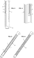
- the figure 2 is a front view of the proximal end of the rod 1.
- the housing 4 is in this case a groove of rectangular section in which the optical fiber bundle 5 is completely contained.
- a prism 6 of fixed square base of the beam is arranged at the distal end of the groove, vis-à-vis the observation window (not shown here).
- Diametrically opposed to the groove 4 is arranged a flat bearing the capture surface 2, which is here micro-structured by means of projecting studs.
- the figure 3 is a side view of the rod, the housing 4 being a groove diametrically opposed to the capture surface 2.
- the figure 4 is a view of the distal end of the groove, which contains the beam 5 and a return optical system 6 arranged at the end of the beam.
- the excitation and detection system typically comprises a light source L (for example a laser) and a photodetector D (preferably a matrix photodetector).
- the light source emits light at an excitation wavelength.
- the photodetector is arranged to detect light at an emission wavelength, the latter being produced in particular by a biological tissue in response to the excitation light.
- the proximal end of the beam, the light source and the photodetector are advantageously coupled by a coupling optical system C, for example a dichroic mirror.
- the photodetector is preferably coupled to a filter, for example an interference filter, whose bandwidth is centered on the fluorescence wavelength (emission wavelength).
- a filter for example an interference filter, whose bandwidth is centered on the fluorescence wavelength (emission wavelength).
- This filter can be arranged on the dichroic mirror, or between the latter and the photodetector.
- the rod 1 is arranged in the guide tube 7 so that the observation window is opposite the opening 70 (cf. figure 5 ).
- the optical fibers collect the excitation light signal emitted by the light source L which is coupled to the proximal end of the beam to the distal end of the beam.
- the signal is deflected by the optical feedback system 6 and transmitted to the external environment of the tube through the observation window 3.
- the signal comes to excite fluorescent markers that have previously been injected to the patient who must undergo the sampling. , or endogenous fluorescent markers, naturally present in biological tissues.
- Said markers then emit a fluorescence signal, which is transmitted through the observation window 3, deflected by the optical redirection system 6 and led by the optical fibers to the photodetector D through the optical coupling system C, in the opposite direction to that of the excitation signal.
- the photodetector is adapted to detect a fluorescence signal emitted by the tissues and therefore indicates the presence or absence of the tissues of interest, the latter generating a fluorescence signal detectable by the photodetector D.
- the practitioner brings the capture surface 2 opposite the opening 70 to put it in contact with the tissues (cf. figure 6 ).
- the observation window 3 is located at the same longitudinal position of the rod as the capture surface but angularly offset.
- This angular offset is for example 180 ° (the capture surface and the observation window being diametrically opposed) but any other angle can be chosen.
- the device comprises an angular indexing system which allows it to easily position either the observation window 3 or the capture surface 2 vis-à-vis the opening 70 of the guide tube 7.
- the practitioner immobilizes the guide tube 7 and merely rotate the rod 1 to bring the capture surface 2. It is thus certain to perform the sampling in the same region as the one he observed and selected.
Description
La présente invention concerne un dispositif de prélèvement d'un tissu biologique.The present invention relates to a device for sampling a biological tissue.
Le prélèvement de tissus biologiques dans certains organes d'un être vivant se révèle particulièrement complexe du fait des risques de lésion de l'organe dans lequel est effectué le prélèvement.The removal of biological tissue in certain organs of a living being is particularly complex because of the risk of injury to the organ in which the sample is taken.
Tel est le cas par exemple des tumeurs du cerveau, qui sont peu accessibles à la biopsie compte tenu des risques encourus en termes de lésions cognitives irréversibles.This is the case, for example, of brain tumors, which are not very accessible to the biopsy taking into account the risks incurred in terms of irreversible cognitive lesions.
Le document
Le document
Par simple contact entre la surface de capture - qui est avantageusement micro-structurée ou poreuse - et le tissu, on obtient une capture de cellules et de macromolécules dans des territoires du système nerveux inaccessibles par chirurgie.By simple contact between the capture surface - which is advantageously micro-structured or porous - and the tissue, we obtain a capture of cells and macromolecules in territories of the nervous system inaccessible by surgery.
Compte tenu du fait que la taille de la tumeur peut être faible, il est nécessaire que la surface de capture soit amenée de manière précise au niveau de la tumeur afin de prélever les cellules et macromolécules d'intérêt.In view of the fact that the size of the tumor may be small, it is necessary that the capture surface is precisely brought to the tumor in order to collect the cells and macromolecules of interest.
Cependant, il est relativement complexe de localiser précisément la zone anatomique où est effectué le prélèvement au moyen de ce dispositif, le praticien ne pouvant visualiser directement l'organe dans lequel il est introduit.However, it is relatively complex to precisely locate the anatomical area where the sample is taken by means of this device, the practitioner can not directly visualize the organ into which it is introduced.
A cet effet, une possibilité est de rendre le dispositif de prélèvement compatible avec l'imagerie par résonance magnétique (IRM) - c'est-à-dire typiquement en le réalisant dans des matériaux non magnétiques -, ce qui permet d'observer par cette technique d'imagerie l'introduction du dispositif de prélèvement dans l'organe et de vérifier l'emplacement de la surface de capture.For this purpose, one possibility is to make the sampling device compatible with magnetic resonance imaging (MRI) - that is to say, typically by performing it in non-magnetic materials -, which allows to observe by this imaging technique the introduction of the sampling device into the organ and to verify the location of the capture surface.
Cependant, la mise en oeuvre du prélèvement sous IRM pose des difficultés en termes de disponibilité de l'équipement.However, the implementation of the MRI sampling poses difficulties in terms of availability of the equipment.
Il serait donc souhaitable de pouvoir procéder à un prélèvement de tissus biologiques dans une zone précise d'un organe en s'affranchissant de l'imagerie par résonance magnétique.It would therefore be desirable to be able to take a biological tissue sample in a specific area of an organ by dispensing with magnetic resonance imaging.
Le document
Un but de l'invention est de concevoir un dispositif de prélèvement de tissus biologiques minimalement invasif qui permette de localiser avec une précision améliorée l'emplacement de la zone dans laquelle est effectué le prélèvement, sans impliquer de système d'imagerie externe tel que l'IRM.An object of the invention is to design a minimally invasive biological tissue sampling device which makes it possible to locate with improved accuracy the location of the area in which the sample is taken without involving an external imaging system such as the MRI.
Conformément à l'invention, il est proposé un dispositif de prélèvement d'un tissu biologique comprenant :
- une tige s'étendant selon un axe longitudinal entre une extrémité proximale et une extrémité distale,
- une surface de capture portée par la tige, destinée à être appliquée contre un tissu biologique,
- une fenêtre d'observation transparente à la lumière visible, agencée dans la surface externe de la tige,
- un logement s'étendant dans la tige, parallèlement à l'axe longitudinal, de l'extrémité proximale jusqu'à la fenêtre d'observation, ledit logement étant apte à recevoir un faisceau de fibres optiques,
- a shaft extending along a longitudinal axis between a proximal end and a distal end,
- a capture surface carried by the stem, intended to be applied against a biological tissue,
- an observation window transparent to visible light, arranged in the outer surface of the rod,
- a housing extending in the rod, parallel to the longitudinal axis, from the proximal end to the observation window, said housing being able to receive a bundle of optical fibers,
De manière avantageuse, la fenêtre d'observation et la surface de capture sont agencées à une même distance de l'extrémité distale de la tige et angulairement espacées.Advantageously, the observation window and the capture surface are arranged at the same distance from the distal end of the rod and angularly spaced apart.
Ledit logement du faisceau de fibres optiques comprend une rainure agencée dans la surface externe de la tige.Said housing of the optical fiber bundle comprises a groove arranged in the outer surface of the rod.
Selon un mode de réalisation, le dispositif comprend en outre :
- un faisceau de fibres optiques disposé dans le logement de la tige de telle sorte qu'une extrémité distale dudit faisceau soit agencée au voisinage de la fenêtre d'observation et
- un système optique de renvoi adapté pour réaliser un couplage optique entre l'extrémité distale du faisceau et la fenêtre d'observation.
- an optical fiber bundle disposed in the housing of the rod so that a distal end of said bundle is arranged in the vicinity of the viewing window and
- an optical return system adapted to perform an optical coupling between the distal end of the beam and the observation window.
Selon une forme d'exécution, le système optique de renvoi comprend une lame réfléchissante orientée d'un angle compris entre 40 et 50° par rapport à l'axe longitudinal de la tige.According to one embodiment, the optical return system comprises a reflecting plate oriented at an angle of between 40 and 50 ° with respect to the longitudinal axis of the rod.
De manière avantageuse, ladite lame réfléchissante fait partie d'un prisme.Advantageously, said reflecting plate is part of a prism.
Selon un mode de réalisation, le prisme comprenant ladite lame réfléchissante est solidaire de l'extrémité distale du faisceau de fibres optiques.According to one embodiment, the prism comprising said reflecting plate is integral with the distal end of the optical fiber bundle.
De manière alternative, le système optique de renvoi consiste en une extrémité distale biseautée des fibres optiques formant le faisceau.Alternatively, the optical return system consists of a beveled distal end of the optical fibers forming the beam.
Le dispositif peut en outre comprendre un tube guide dans lequel la tige est apte à coulisser, ledit tube guide comprenant une ouverture latérale agencée de telle sorte que lorsque la tige est introduite dans le tube guide la surface de capture et la fenêtre d'observation viennent en vis-à-vis de ladite ouverture latérale selon l'orientation angulaire respective du tube guide et de la tige.The device may further comprise a guide tube in which the rod is slidable, said guide tube comprising a lateral opening arranged so that when the rod is introduced into the guide tube the capture surface and the observation window come vis-à-vis said lateral opening according to the respective angular orientation of the guide tube and the rod.
La surface de capture est avantageusement située dans une région distale de la tige.The capture surface is advantageously located in a distal region of the stem.
Selon un mode de réalisation, la surface de capture est revêtue d'une couche de fonctionnalisation.According to one embodiment, the capture surface is coated with a functionalization layer.
La tige est par exemple en inox ou en PEEK.The rod is for example stainless steel or PEEK.
Selon une forme d'exécution avantageuse, la tige présente une section décroissante de son extrémité proximale vers son extrémité distale.According to an advantageous embodiment, the stem has a decreasing section from its proximal end towards its distal end.
D'autres caractéristiques et avantages de l'invention ressortiront de la description détaillée qui va suivre, en référence aux dessins annexés sur lesquels :
- la
figure 1 est une vue en coupe d'un dispositif de prélèvement selon un mode de réalisation, - la
figure 2 est une vue de face de l'extrémité proximale de la tige du dispositif de prélèvement, - la
figure 3 est une vue en perspective de côté de la tige, - la
figure 4 est une vue en perspective de la région de la fenêtre d'observation dans la tige, - la
figure 5 est une vue en perspective de la tige dans le tube guide, en position d'observation des tissus, - la
figure 6 est une vue en perspective de la tige dans le tube guide, en position de prélèvement d'un tissu biologique, - la
figure 7 est une vue en perspective de la tige selon une forme d'exécution particulière de l'invention.
- the
figure 1 is a sectional view of a sampling device according to an embodiment, - the
figure 2 is a front view of the proximal end of the stem of the sampling device, - the
figure 3 is a side perspective view of the stem, - the
figure 4 is a perspective view of the region of the observation window in the stem, - the
figure 5 is a perspective view of the rod in the guide tube, in the tissue observation position, - the
figure 6 is a perspective view of the rod in the guide tube, in the position of sampling a biological tissue, - the
figure 7 is a perspective view of the rod according to a particular embodiment of the invention.
La
Le dispositif 100 comprend une tige 1 qui s'étend selon un axe longitudinal X entre une extrémité proximale 1a et une extrémité distale 1b. Par convention, on désigne par « proximal » le côté le plus proche de la main du praticien et par « distal » le côté le plus éloigné, destiné à entrer en contact avec les tissus.The
La tige 1 est réalisée en un matériau biocompatible. La tige 1 peut ainsi être réalisée en acier inoxydable, ou encore en un matériau plastique, tel que le PEEK qui présente, par rapport à l'inox, d'être compatible avec l'IRM.The
Le diamètre de la tige est typiquement compris entre 500 µm et 2000 µm, de préférence entre 800 µm et 1200 µm. Avantageusement, un diamètre de 1200 µm permet une insertion correcte dans un tube guide existant.The diameter of the rod is typically between 500 μm and 2000 μm, preferably between 800 μm and 1200 μm. Advantageously, a diameter of 1200 microns allows a correct insertion into an existing guide tube.
De préférence, la section transversale de la tige 1 décroit entre son extrémité proximale et son extrémité distale. Par exemple, comme illustré sur la
La tige 1 porte une surface de capture 2 qui est destinée à être appliquée contre un tissu biologique au niveau duquel on souhaite effectuer un prélèvement.The
La surface de capture 2 est généralement une surface plane et de contour rectangulaire, bien qu'elle ne soit pas limitée à cette seule forme. La longueur de la surface de capture est de préférence agencée parallèlement à l'axe longitudinal.The
La tige 1 peut présenter un méplat agencé à la périphérie de la tige et sur lequel on solidarise la surface de capture, par exemple par collage ou par tout autre moyen. La liaison de la surface de capture vis-à-vis de la tige peut être amovible ou non. Le méplat est avantageusement conçu pour que lorsque la surface de capture 2 est assemblée sur la tige 1, elle soit inscrite dans la section circulaire de la tige et ne présente pas de protubérance par rapport à la surface périphérique de la tige.The
Tout en étant plane à l'échelle macroscopique, la surface de capture peut être micro-structurée de sorte à présenter des protubérances permettant de prélever un tissu biologique par micro-abrasion. Par exemple, lesdites protubérances peuvent consister en des piliers hexagonaux de 50 µm de hauteur et 80 µm de diamètre.While being flat on a macroscopic scale, the capture surface may be micro-structured so as to have protuberances for removing a biological tissue by micro-abrasion. For example, said protuberances may consist of hexagonal pillars of 50 μm in height and 80 μm in diameter.
De manière alternative, la surface de capture peut être la surface d'un matériau nanoporeux.Alternatively, the capture surface may be the surface of a nanoporous material.
Le silicium est fréquemment employé comme matériau de surface de capture, quel que soit le mode de réalisation considéré.Silicon is frequently used as a capture surface material, regardless of the embodiment considered.
Par ailleurs, la surface de capture 2 peut être revêtue d'une couche de fonctionnalisation favorisant le greffage d'analytes d'intérêt. Dans le présent texte, le terme « analyte » désigne une espèce chimique ou biologique, en particulier une protéine ou une cellule. La couche de fonctionnalisation peut notamment être anionique.Furthermore, the
De préférence, la surface de capture 2 est située dans une région distale de la tige 1.Preferably, the
Par ailleurs, la tige 1 comprend une fenêtre d'observation 3 et un logement 4 s'étendant dans la tige depuis l'extrémité proximale 1a jusqu'à ladite fenêtre d'observation. Comme on le verra en détail plus bas, ledit logement 4 est destiné à recevoir un faisceau de fibres optiques.Furthermore, the
Par « fenêtre » on entend dans le présent texte une surface adaptée pour transmettre la lumière visible entre l'environnement extérieur et le logement 4. Ladite fenêtre est donc obtenue en pratiquant une ouverture entre la surface externe de la tige et le logement 4. La fenêtre peut éventuellement être matérialisée par un matériau transparent à la lumière visible, ce matériau pouvant être organique (tel que du plexiglas) ou inorganique (tel que du verre). Cependant, la présence d'un tel matériau n'est pas indispensable et la fenêtre peut simplement consister en un espace libre entre la surface externe de la tige 1 et le logement 4.By "window" is meant in the present text a surface adapted to transmit the visible light between the external environment and the
Selon un mode de réalisation, le logement 4 peut consister en un perçage pratiqué dans l'épaisseur de la tige.According to one embodiment, the
De manière alternative, le logement 4 peut consister en une rainure pratiquée dans la surface externe de la tige 1, qui est généralement plus facile à réaliser par usinage. Ladite rainure peut présenter par exemple une section carrée ou rectangulaire.Alternatively, the
Les dimensions de ladite rainure sont adaptées à celles du faisceau de fibres optiques, de sorte à permettre l'insertion dudit faisceau dans ladite rainure. De préférence, le faisceau de fibres optiques est agencé de manière amovible dans le logement ; il est par exemple retenu par serrage dans le logement 4. Le faisceau peut être inséré partiellement dans la rainure, c'est-à-dire qu'une partie du faisceau s'étend au-delà des parois de la rainure ; de manière alternative, le faisceau est entièrement logé dans la rainure, sa surface externe ne dépassant pas de l'enveloppe définie par les parois de la rainure.The dimensions of said groove are adapted to those of the optical fiber bundle, so as to allow insertion of said bundle in said groove. Preferably, the optical fiber bundle is removably arranged in the housing; it is for example retained by clamping in the
Lorsque le faisceau de fibres optiques est inséré en totalité dans la rainure, l'espace laissé libre dans la rainure autour du faisceau peut être comblé au moyen d'un polymère biocompatible appliqué à l'état liquide puis durci de manière à constituer un confinement du faisceau de fibres. De préférence, ledit polymère assure en outre une continuité de la surface externe de la tige pour conserver sa section circulaire. Ledit polymère est de préférence un alginate, qui est biocompatible et permet un comblement réversible de la rainure. En effet, cet alginate peut ensuite être dissous dans un bain d'un solvant approprié, ce qui permet de retirer le faisceau de fibres optiques de la rainure.When the bundle of optical fibers is fully inserted into the groove, the space left free in the groove around the bundle can be filled by means of a biocompatible polymer applied in the liquid state and then hardened to form a confinement of the bundle. fiber bundle. Preferably, said polymer further ensures a continuity of the outer surface of the rod to maintain its circular section. Said polymer is preferably an alginate, which is biocompatible and allows a reversible filling of the groove. Indeed, this alginate can then be dissolved in a bath of a suitable solvent, which makes it possible to remove the optical fiber bundle from the groove.
Le faisceau de fibres optiques 5 comprend avantageusement de l'ordre de 3000 fibres optiques agencées en un faisceau de section circulaire de 0,3 mm de diamètre. Un tel faisceau est celui équipant l'endoscope distribué par la société Mauna Kea Technologies sous la référence Cellvizio™.The
Les fibres optiques sont choisies de sorte à guider toute longueur d'onde permettant la caractérisation spectrale des tissus biologiques. Typiquement, les fibres optiques doivent guider une plage de longueur d'onde comprise entre l'ultraviolet et l'infrarouge, ce dernier présentant une bien meilleure pénétrance dans les tissus.The optical fibers are chosen to guide any wavelength for spectral characterization of biological tissues. Typically, the optical fibers must guide a wavelength range between ultraviolet and infrared, the latter having a much better penetration into the tissues.
Le faisceau 5 présente une extrémité proximale qui est reliée à un système d'excitation et de détection, et une extrémité distale qui, lorsque le faisceau est dans sa position d'utilisation dans la tige 1, est agencée au voisinage de la fenêtre d'observation 3.The
Le dispositif 100 comprend par ailleurs un système optique de renvoi 6 adapté pour réaliser un couplage optique entre l'extrémité distale du faisceau et la fenêtre d'observation. A cet effet, ledit système 6 est agencé au voisinage de la fenêtre 3. Le système de couplage optique peut être solidaire de la tige (il peut par exemple être formé d'un prisme collé à l'extrémité distale de la rainure formant le logement 4, en vis-à-vis de la fenêtre d'observation 3) ou bien du faisceau de fibres, auquel cas il est fixé à l'extrémité distale de ce faisceau.The
Selon un mode de réalisation, le système de couplage optique est constitué par l'extrémité du faisceau qui est taillée en biseau, l'angle du biseau étant de l'ordre de 40 à 50°, de préférence 45°. Selon ce mode de réalisation, l'extrémité du faisceau forme un plan incliné ; ainsi, chaque fibre du faisceau est apte à collecter un signal lumineux dont l'angle d'incidence est incliné par rapport à l'axe longitudinal du faisceau.According to one embodiment, the optical coupling system is constituted by the end of the beam which is bevelled, the angle of the bevel being of the order of 40 to 50 °, preferably 45 °. According to this embodiment, the end of the beam forms an inclined plane; thus, each fiber of the beam is able to collect a light signal whose angle of incidence is inclined relative to the longitudinal axis of the beam.
Selon un autre mode de réalisation, le système de renvoi optique est une lame réfléchissante, orientée d'environ 40 à 50°, de préférence 45°, par rapport à l'axe longitudinal X.According to another embodiment, the optical redirection system is a reflective plate, oriented approximately 40 to 50 °, preferably 45 °, with respect to the longitudinal axis X.
Ladite lame réfléchissante peut appartenir à un prisme, ledit prisme étant solidaire de l'extrémité distale du faisceau de fibres optiques, par exemple par sertissage, par collage ou par tout autre moyen. Le prisme présente typiquement une section carrée dont la longueur est égale au diamètre du faisceau de fibres optiques.Said reflecting plate may belong to a prism, said prism being integral with the distal end of the optical fiber bundle, for example by crimping, gluing or by any other means. The prism typically has a square section whose length is equal to the diameter of the optical fiber bundle.
De préférence, le système de renvoi optique est configuré de façon à dévier la lumière émise par le faisceau de fibres selon une direction sensiblement orthogonale à l'axe longitudinal X. Dans ce cas, le faisceau est apte à collecter, par son extrémité distale, une lumière dont l'angle d'incidence est orthogonal à l'axe longitudinal X.Preferably, the optical redirection system is configured to deflect the light emitted by the fiber bundle in a direction substantially orthogonal to the longitudinal axis X. In this case, the beam is able to collect, by its distal end, a light whose angle of incidence is orthogonal to the longitudinal axis X.
Le dispositif 100 comprend avantageusement un tube guide 7 à l'intérieur duquel la tige 1 peut coulisser. Le tube guide comprend une ouverture latérale 70 de telle sorte que lorsque la tige est insérée dans le tube, l'ouverture 70 est en vis-à-vis de la portion de la tige qui porte la surface de capture et dans laquelle est ménagée la fenêtre d'observation 3. La tige 1 est alors libre en translation et en rotation dans le tube guide 7. Cela permet de placer, alternativement, la fenêtre 3 ou la surface de capture 2 face à l'ouverture 70, comme détaillé dans l'exemple décrit ci-après. Le tube guide 7 a pour fonction de protéger la tige et la surface de capture, qui peuvent coulisser dans le tube sans être en contact avec les tissus. Le tube guide est en un matériau biocompatible tel que de l'inox. Le diamètre intérieur du tube guide est typiquement compris entre 1000 et 3000 µm, par exemple 1200 µm.The
Lorsque la tige présente une section décroissante de son extrémité proximale vers son extrémité distale (mode de réalisation illustré sur la
La
Le logement 4 est dans ce cas une rainure de section rectangulaire dans laquelle le faisceau de fibres optiques 5 est entièrement contenu. Un prisme 6 de base carrée solidaire du faisceau est agencé à l'extrémité distale de la rainure, en vis-à-vis de la fenêtre d'observation (non représentée ici). Diamétralement opposé à la rainure 4 est agencé un méplat portant la surface de capture 2, qui est ici micro-structurée au moyen de plots saillants.The
La
La
Revenant maintenant à la
Le photodétecteur est de préférence couplé à un filtre, par exemple un filtre interférentiel, dont la bande passante est centrée sur la longueur d'onde de fluorescence (longueur d'onde d'émission). Ce filtre peut être disposé sur le miroir dichroïque, ou entre ce dernier et le photodétecteur.The photodetector is preferably coupled to a filter, for example an interference filter, whose bandwidth is centered on the fluorescence wavelength (emission wavelength). This filter can be arranged on the dichroic mirror, or between the latter and the photodetector.
Pour la mise en oeuvre d'une opération de prélèvement, on agence la tige 1 dans le tube guide 7 de sorte que la fenêtre d'observation soit en vis-à-vis de l'ouverture 70 (cf.
Le faisceau étant en position dans son logement de la tige, les fibres optiques collectent le signal lumineux d'excitation émis par la source lumineuse L qui est couplée à l'extrémité proximale du faisceau jusqu'à l'extrémité distale du faisceau. Le signal est dévié par le système de renvoi optique 6 et transmis vers l'environnement extérieur du tube à travers la fenêtre d'observation 3. Ainsi, le signal vient exciter des marqueurs fluorescents qui ont préalablement été injectés au patient qui doit subir le prélèvement, ou des marqueurs fluorescents endogènes, naturellement présents dans les tissus biologiques.The beam being in position in its housing of the rod, the optical fibers collect the excitation light signal emitted by the light source L which is coupled to the proximal end of the beam to the distal end of the beam. The signal is deflected by the
Lesdits marqueurs émettent alors un signal de fluorescence, qui est transmis au travers de la fenêtre d'observation 3, dévié par le système de renvoi optique 6 et conduit par les fibres optiques jusqu'au photodétecteur D au travers du système optique de couplage C, selon le trajet inverse de celui du signal d'excitation.Said markers then emit a fluorescence signal, which is transmitted through the
Le faisceau de fibres optiques assure ainsi deux fonctions :
- d'une part, l'illumination des tissus éclairés au travers de la fenêtre d'observation 3 ;
- d'autre part, la collection d'un signal de fluorescence émis par les tissus éclairés.
- on the one hand, the illumination of the illuminated tissues through the
observation window 3; - on the other hand, the collection of a fluorescence signal emitted by the illuminated tissues.
Le photodétecteur est adapté pour détecter un signal de fluorescence émis par les tissus et par conséquent indicateur de la présence ou non des tissus d'intérêt, ces derniers générant un signal de fluorescence détectable par le photodétecteur D.The photodetector is adapted to detect a fluorescence signal emitted by the tissues and therefore indicates the presence or absence of the tissues of interest, the latter generating a fluorescence signal detectable by the photodetector D.
Si l'analyse effectuée par le photodétecteur montre que le dispositif est situé dans une région propice, le praticien amène la surface de capture 2 en vis-à-vis de l'ouverture 70 pour la mettre au contact des tissus (cf.
De préférence, la fenêtre d'observation 3 est située à la même position longitudinale de la tige que la surface de capture mais décalée angulairement. Ce décalage angulaire est par exemple de 180° (la surface de capture et la fenêtre d'observation étant diamétralement opposées) mais tout autre angle peut être choisi. De manière avantageuse, le dispositif comprend un système d'indexation angulaire qui lui permet de positionner aisément soit la fenêtre d'observation 3 soit la surface de capture 2 en vis-à-vis de l'ouverture 70 du tube guide 7. Ainsi, une fois que le dispositif est en place dans une région propice au prélèvement, le praticien immobilise le tube guide 7 et se contente de faire pivoter la tige 1 pour amener la surface de capture 2. Il est ainsi certain d'effectuer le prélèvement dans la même région que celle qu'il a observée et choisie.Preferably, the
Le cas échéant, plusieurs prélèvements peuvent être effectués dans la même région : il suffit à cet effet de retirer du tube guide la tige portant la surface de capture sur laquelle un échantillon a été prélevé et d'insérer une nouvelle tige portant une surface de capture vierge.If necessary, several samples may be taken in the same region: it suffices for this purpose to remove from the guide tube the rod carrying the capture surface on which a sample was taken and to insert a new rod carrying a capture surface. Virgin.
Par ailleurs, une fois que le tube guide a été positionnée dans la région souhaitée, il est possible de retirer le faisceau de fibres optiques de la tige et d'insérer dans le tube guide la tige pourvue uniquement de la surface de capture.On the other hand, once the guide tube has been positioned in the desired region, it is possible to remove the optical fiber bundle from the rod and insert into the guide tube the rod provided solely with the capture surface.
Enfin, on a mentionné ci-dessus la manipulation du dispositif de prélèvement par un chirurgien mais il est également possible que le dispositif soit manipulé par un robot.Finally, it has been mentioned above the manipulation of the sampling device by a surgeon but it is also possible that the device is manipulated by a robot.
Claims (13)
- A device (100) for sampling a biological tissue comprising:- a rod (1) extending along a longitudinal axis (X) between a proximal end (1a) and a distal end (1b),- a capture surface (2) borne by the rod (1), intended to be applied against a biological tissue,- an observation window (3) transparent to visible light, arranged in the external surface of the rod (1),- a housing (4) extending in the rod, parallel to the longitudinal axis, from the proximal end (1a) as far as the observation window (3), said housing being able to receive a bundle of optical fibres,said device (100) being characterized in that the capture surface is nanoporous or has protrusions adapted for sampling a biological tissue by micro abrasion and in that the housing (4) for the bundle of optical fibres comprises a groove arranged in the external surface of the rod.
- The device according to claim 1, wherein the observation window (3) and the capture surface (2) are arranged at a same distance from the distal end of the rod and spaced out angularly.
- The device according to one of claims 1 to 2, comprising:- a bundle (5) of optical fibres positioned in the housing (4) of the rod so that a distal end of said bundle is arranged in the vicinity of the observation window (3) and- an optical return system (6) adapted for carrying out optical coupling between the distal end of the bundle and the observation window.
- The device according to claim 3, wherein the optical return system comprises a reflective plate orientated at an angle comprised between 40 and 50° relative to the longitudinal axis (X) of the rod.
- The device according to claim 4, wherein the reflective plate is part of a prism.
- The device according to claim 5, wherein the prism comprising the reflective plate is secured to the distal end of the bundle of optical fibres.
- The device according to claim 3, wherein the optical return system consists in a bevelled distal end of the optical fibres forming the bundle.
- The device according to one of claims 1 to 7, further comprising a guide tube (7) in which the rod (1) is able to slide, said guide tube comprising a lateral opening (70) arranged so that, when the rod is introduced into the guide tube, the capture surface and the observation window are facing said lateral opening (70) depending on the respective angular orientation of the guide tube and of the rod.
- The device according to the previous claim, further comprising an angular indexation system which allows positioning either the capture surface (2) or the observation window (3) facing the lateral opening (70) of the guide tube (7).
- The device according to one of claims 1 to 9, wherein the capture surface is located in a distal region of the rod (1).
- The device according to one of claims 1 to 10, wherein the capture surface is coated with a functionalization layer.
- The device according to one of claims 1 to 11, wherein the rod (1) is in stainless steel or in PEEK.
- The device according to one of claims 1 to 12, wherein the rod (1) has a decreasing section from its proximal end (1a) to its distal end (1b).
Applications Claiming Priority (1)
| Application Number | Priority Date | Filing Date | Title |
|---|---|---|---|
| FR1363695A FR3015882B1 (en) | 2013-12-30 | 2013-12-30 | DEVICE FOR TAKING BIOLOGICAL TISSUE |
Publications (2)
| Publication Number | Publication Date |
|---|---|
| EP2888990A1 EP2888990A1 (en) | 2015-07-01 |
| EP2888990B1 true EP2888990B1 (en) | 2018-11-28 |
Family
ID=50473497
Family Applications (1)
| Application Number | Title | Priority Date | Filing Date |
|---|---|---|---|
| EP14200532.1A Active EP2888990B1 (en) | 2013-12-30 | 2014-12-30 | Device for sampling a biological tissue |
Country Status (3)
| Country | Link |
|---|---|
| US (1) | US10213190B2 (en) |
| EP (1) | EP2888990B1 (en) |
| FR (1) | FR3015882B1 (en) |
Family Cites Families (17)
| Publication number | Priority date | Publication date | Assignee | Title |
|---|---|---|---|---|
| US3556085A (en) * | 1968-02-26 | 1971-01-19 | Olympus Optical Co | Optical viewing instrument |
| US3945375A (en) * | 1972-04-04 | 1976-03-23 | Surgical Design Corporation | Rotatable surgical instrument |
| DK131542C (en) * | 1974-02-06 | 1976-02-09 | Akad Tekn Videnskaber | SURGICAL INSTRUMENT FOR SAMPLING BIOLOGICAL SAMPLES |
| US4566438A (en) * | 1984-10-05 | 1986-01-28 | Liese Grover J | Fiber-optic stylet for needle tip localization |
| US5280788A (en) * | 1991-02-26 | 1994-01-25 | Massachusetts Institute Of Technology | Devices and methods for optical diagnosis of tissue |
| US6564087B1 (en) * | 1991-04-29 | 2003-05-13 | Massachusetts Institute Of Technology | Fiber optic needle probes for optical coherence tomography imaging |
| WO1995005112A1 (en) * | 1993-08-18 | 1995-02-23 | Vista Medical Technologies | Optical surgical device |
| US6346086B1 (en) * | 1998-04-23 | 2002-02-12 | Cook Urological Inc. | Endocervical and exocervical cell collection device |
| US6689142B1 (en) * | 1999-04-26 | 2004-02-10 | Scimed Life Systems, Inc. | Apparatus and methods for guiding a needle |
| US9033897B2 (en) * | 2005-01-14 | 2015-05-19 | Institute National De La Sante Et De La Recherche Medicale | Method for determining the molecular composition of a target tissue or another body structure, and its diagnostic applications |
| FR2881339B1 (en) | 2005-02-02 | 2009-07-10 | Commissariat Energie Atomique | CONTACT MOLECULAR SAMPLING DEVICE |
| US20090082695A1 (en) * | 2007-06-25 | 2009-03-26 | Led Medical Diagnostics, Inc. | Methods, systems and apparatus relating to colposcopic-type viewing extension devices |
| US8369915B2 (en) * | 2009-11-06 | 2013-02-05 | Wisconsin Alumni Research Foundation | Integrated miniaturized fiber optic probe |
| US8911433B2 (en) * | 2009-11-18 | 2014-12-16 | Boston Scientific Scimed, Inc. | Methods and apparatus related to a distal end of a side-fire optical fiber having multiple capillary components |
| US8672929B2 (en) * | 2010-12-15 | 2014-03-18 | Ams Research Corporation | Laser probe tip |
| US9763744B2 (en) * | 2011-12-22 | 2017-09-19 | Trustees Of Dartmouth College | Biopsy device with integrated optical spectroscopy guidance |
| FR2985164B1 (en) * | 2011-12-29 | 2015-02-27 | Commissariat Energie Atomique | DEVICE AND METHOD FOR COLLECTING AND ANALYZING BIOLOGICAL OR BIOCHEMICAL SPECIES. |
-
2013
- 2013-12-30 FR FR1363695A patent/FR3015882B1/en active Active
-
2014
- 2014-12-30 EP EP14200532.1A patent/EP2888990B1/en active Active
- 2014-12-30 US US14/585,361 patent/US10213190B2/en active Active
Non-Patent Citations (1)
| Title |
|---|
| None * |
Also Published As
| Publication number | Publication date |
|---|---|
| FR3015882A1 (en) | 2015-07-03 |
| FR3015882B1 (en) | 2020-01-17 |
| US10213190B2 (en) | 2019-02-26 |
| US20150182207A1 (en) | 2015-07-02 |
| EP2888990A1 (en) | 2015-07-01 |
Similar Documents
| Publication | Publication Date | Title |
|---|---|---|
| EP2456354B1 (en) | Sharp fibrous needle probe for the in-depth optical diagnosis of tumors by endogenous fluorescence | |
| Latka et al. | Fiber optic probes for linear and nonlinear Raman applications–Current trends and future development | |
| JP5108649B2 (en) | Objective lens adapter | |
| RU2746895C2 (en) | Device for three-dimensional staining of biopsy tissue | |
| US11064982B2 (en) | Systems, devices and methods for tissue removal and analysis | |
| EP2773259B1 (en) | Raman spectroscopy probe | |
| US20100234684A1 (en) | Multifunctional endoscopic device and methods employing said device | |
| US10463349B2 (en) | Device for obtaining 3D biopsy | |
| KR20010110346A (en) | Imaging of tissue using polarized light | |
| CA3051489C (en) | Needle assembly and system for collection and optical interrogation of a biological sample | |
| JP2002136469A (en) | System for analyzing adhesion substance on inner wall of blood vessel | |
| EP2888990B1 (en) | Device for sampling a biological tissue | |
| EP2477554B1 (en) | Surgical instrument for molecular sampling | |
| EP2228003A1 (en) | Multifunctional endoscopic device and methods employing said device | |
| EP4285174A1 (en) | Devices for ex vivo microscopic analysis of samples and in vivo microscopic analysis of the skin | |
| EP3465320B1 (en) | Device and method for providing illumination for total-internal-reflection fluorescence microscopy | |
| US20200015684A1 (en) | Probe for optical spectroscopy | |
| WO2014096138A1 (en) | Device for preserving a biological sample | |
| FR3034869A1 (en) | DEVICE, KIT AND METHOD FOR CALIBRATING FLUORESCENCE |
Legal Events
| Date | Code | Title | Description |
|---|---|---|---|
| PUAI | Public reference made under article 153(3) epc to a published international application that has entered the european phase |
Free format text: ORIGINAL CODE: 0009012 |
|
| 17P | Request for examination filed |
Effective date: 20141230 |
|
| AK | Designated contracting states |
Kind code of ref document: A1 Designated state(s): AL AT BE BG CH CY CZ DE DK EE ES FI FR GB GR HR HU IE IS IT LI LT LU LV MC MK MT NL NO PL PT RO RS SE SI SK SM TR |
|
| AX | Request for extension of the european patent |
Extension state: BA ME |
|
| R17P | Request for examination filed (corrected) |
Effective date: 20160104 |
|
| RBV | Designated contracting states (corrected) |
Designated state(s): AL AT BE BG CH CY CZ DE DK EE ES FI FR GB GR HR HU IE IS IT LI LT LU LV MC MK MT NL NO PL PT RO RS SE SI SK SM TR |
|
| GRAJ | Information related to disapproval of communication of intention to grant by the applicant or resumption of examination proceedings by the epo deleted |
Free format text: ORIGINAL CODE: EPIDOSDIGR1 |
|
| GRAP | Despatch of communication of intention to grant a patent |
Free format text: ORIGINAL CODE: EPIDOSNIGR1 |
|
| RAP1 | Party data changed (applicant data changed or rights of an application transferred) |
Owner name: UNIVERSITE GRENOBLE ALPES Owner name: CENTRE HOSPITALIER UNIVERSITAIRE GRENOBLE ALPES Owner name: COMMISSARIAT A L'ENERGIE ATOMIQUE ET AUX ENERGIES |
|
| GRAP | Despatch of communication of intention to grant a patent |
Free format text: ORIGINAL CODE: EPIDOSNIGR1 |
|
| INTG | Intention to grant announced |
Effective date: 20180827 |
|
| RAP1 | Party data changed (applicant data changed or rights of an application transferred) |
Owner name: CENTRE HOSPITALIER UNIVERSITAIRE GRENOBLE ALPES Owner name: UNIVERSITE GRENOBLE ALPES Owner name: COMMISSARIAT A L'ENERGIE ATOMIQUE ET AUX ENERGIES |
|
| RIN1 | Information on inventor provided before grant (corrected) |
Inventor name: MOMBRUN, ADRIEN Inventor name: BOUAMRANI, ALI Inventor name: BERGER, FRANCOIS Inventor name: DREYFUS, MATTHIEU |
|
| GRAS | Grant fee paid |
Free format text: ORIGINAL CODE: EPIDOSNIGR3 |
|
| GRAA | (expected) grant |
Free format text: ORIGINAL CODE: 0009210 |
|
| AK | Designated contracting states |
Kind code of ref document: B1 Designated state(s): AL AT BE BG CH CY CZ DE DK EE ES FI FR GB GR HR HU IE IS IT LI LT LU LV MC MK MT NL NO PL PT RO RS SE SI SK SM TR |
|
| REG | Reference to a national code |
Ref country code: CH Ref legal event code: EP |
|
| REG | Reference to a national code |
Ref country code: AT Ref legal event code: REF Ref document number: 1069256 Country of ref document: AT Kind code of ref document: T Effective date: 20181215 |
|
| REG | Reference to a national code |
Ref country code: DE Ref legal event code: R096 Ref document number: 602014036860 Country of ref document: DE |
|
| REG | Reference to a national code |
Ref country code: IE Ref legal event code: FG4D Free format text: LANGUAGE OF EP DOCUMENT: FRENCH |
|
| REG | Reference to a national code |
Ref country code: NL Ref legal event code: MP Effective date: 20181128 |
|
| REG | Reference to a national code |
Ref country code: LT Ref legal event code: MG4D |
|
| REG | Reference to a national code |
Ref country code: AT Ref legal event code: MK05 Ref document number: 1069256 Country of ref document: AT Kind code of ref document: T Effective date: 20181128 |
|
| PG25 | Lapsed in a contracting state [announced via postgrant information from national office to epo] |
Ref country code: FI Free format text: LAPSE BECAUSE OF FAILURE TO SUBMIT A TRANSLATION OF THE DESCRIPTION OR TO PAY THE FEE WITHIN THE PRESCRIBED TIME-LIMIT Effective date: 20181128 Ref country code: IS Free format text: LAPSE BECAUSE OF FAILURE TO SUBMIT A TRANSLATION OF THE DESCRIPTION OR TO PAY THE FEE WITHIN THE PRESCRIBED TIME-LIMIT Effective date: 20190328 Ref country code: NO Free format text: LAPSE BECAUSE OF FAILURE TO SUBMIT A TRANSLATION OF THE DESCRIPTION OR TO PAY THE FEE WITHIN THE PRESCRIBED TIME-LIMIT Effective date: 20190228 Ref country code: AT Free format text: LAPSE BECAUSE OF FAILURE TO SUBMIT A TRANSLATION OF THE DESCRIPTION OR TO PAY THE FEE WITHIN THE PRESCRIBED TIME-LIMIT Effective date: 20181128 Ref country code: LV Free format text: LAPSE BECAUSE OF FAILURE TO SUBMIT A TRANSLATION OF THE DESCRIPTION OR TO PAY THE FEE WITHIN THE PRESCRIBED TIME-LIMIT Effective date: 20181128 Ref country code: ES Free format text: LAPSE BECAUSE OF FAILURE TO SUBMIT A TRANSLATION OF THE DESCRIPTION OR TO PAY THE FEE WITHIN THE PRESCRIBED TIME-LIMIT Effective date: 20181128 Ref country code: LT Free format text: LAPSE BECAUSE OF FAILURE TO SUBMIT A TRANSLATION OF THE DESCRIPTION OR TO PAY THE FEE WITHIN THE PRESCRIBED TIME-LIMIT Effective date: 20181128 Ref country code: BG Free format text: LAPSE BECAUSE OF FAILURE TO SUBMIT A TRANSLATION OF THE DESCRIPTION OR TO PAY THE FEE WITHIN THE PRESCRIBED TIME-LIMIT Effective date: 20190228 Ref country code: HR Free format text: LAPSE BECAUSE OF FAILURE TO SUBMIT A TRANSLATION OF THE DESCRIPTION OR TO PAY THE FEE WITHIN THE PRESCRIBED TIME-LIMIT Effective date: 20181128 |
|
| PG25 | Lapsed in a contracting state [announced via postgrant information from national office to epo] |
Ref country code: AL Free format text: LAPSE BECAUSE OF FAILURE TO SUBMIT A TRANSLATION OF THE DESCRIPTION OR TO PAY THE FEE WITHIN THE PRESCRIBED TIME-LIMIT Effective date: 20181128 Ref country code: PT Free format text: LAPSE BECAUSE OF FAILURE TO SUBMIT A TRANSLATION OF THE DESCRIPTION OR TO PAY THE FEE WITHIN THE PRESCRIBED TIME-LIMIT Effective date: 20190328 Ref country code: SE Free format text: LAPSE BECAUSE OF FAILURE TO SUBMIT A TRANSLATION OF THE DESCRIPTION OR TO PAY THE FEE WITHIN THE PRESCRIBED TIME-LIMIT Effective date: 20181128 Ref country code: RS Free format text: LAPSE BECAUSE OF FAILURE TO SUBMIT A TRANSLATION OF THE DESCRIPTION OR TO PAY THE FEE WITHIN THE PRESCRIBED TIME-LIMIT Effective date: 20181128 Ref country code: GR Free format text: LAPSE BECAUSE OF FAILURE TO SUBMIT A TRANSLATION OF THE DESCRIPTION OR TO PAY THE FEE WITHIN THE PRESCRIBED TIME-LIMIT Effective date: 20190301 |
|
| PG25 | Lapsed in a contracting state [announced via postgrant information from national office to epo] |
Ref country code: NL Free format text: LAPSE BECAUSE OF FAILURE TO SUBMIT A TRANSLATION OF THE DESCRIPTION OR TO PAY THE FEE WITHIN THE PRESCRIBED TIME-LIMIT Effective date: 20181128 |
|
| PG25 | Lapsed in a contracting state [announced via postgrant information from national office to epo] |
Ref country code: CZ Free format text: LAPSE BECAUSE OF FAILURE TO SUBMIT A TRANSLATION OF THE DESCRIPTION OR TO PAY THE FEE WITHIN THE PRESCRIBED TIME-LIMIT Effective date: 20181128 Ref country code: DK Free format text: LAPSE BECAUSE OF FAILURE TO SUBMIT A TRANSLATION OF THE DESCRIPTION OR TO PAY THE FEE WITHIN THE PRESCRIBED TIME-LIMIT Effective date: 20181128 Ref country code: PL Free format text: LAPSE BECAUSE OF FAILURE TO SUBMIT A TRANSLATION OF THE DESCRIPTION OR TO PAY THE FEE WITHIN THE PRESCRIBED TIME-LIMIT Effective date: 20181128 Ref country code: IT Free format text: LAPSE BECAUSE OF FAILURE TO SUBMIT A TRANSLATION OF THE DESCRIPTION OR TO PAY THE FEE WITHIN THE PRESCRIBED TIME-LIMIT Effective date: 20181128 |
|
| REG | Reference to a national code |
Ref country code: CH Ref legal event code: PL |
|
| REG | Reference to a national code |
Ref country code: DE Ref legal event code: R097 Ref document number: 602014036860 Country of ref document: DE |
|
| PG25 | Lapsed in a contracting state [announced via postgrant information from national office to epo] |
Ref country code: EE Free format text: LAPSE BECAUSE OF FAILURE TO SUBMIT A TRANSLATION OF THE DESCRIPTION OR TO PAY THE FEE WITHIN THE PRESCRIBED TIME-LIMIT Effective date: 20181128 Ref country code: SM Free format text: LAPSE BECAUSE OF FAILURE TO SUBMIT A TRANSLATION OF THE DESCRIPTION OR TO PAY THE FEE WITHIN THE PRESCRIBED TIME-LIMIT Effective date: 20181128 Ref country code: RO Free format text: LAPSE BECAUSE OF FAILURE TO SUBMIT A TRANSLATION OF THE DESCRIPTION OR TO PAY THE FEE WITHIN THE PRESCRIBED TIME-LIMIT Effective date: 20181128 Ref country code: LU Free format text: LAPSE BECAUSE OF NON-PAYMENT OF DUE FEES Effective date: 20181230 Ref country code: SK Free format text: LAPSE BECAUSE OF FAILURE TO SUBMIT A TRANSLATION OF THE DESCRIPTION OR TO PAY THE FEE WITHIN THE PRESCRIBED TIME-LIMIT Effective date: 20181128 Ref country code: MC Free format text: LAPSE BECAUSE OF FAILURE TO SUBMIT A TRANSLATION OF THE DESCRIPTION OR TO PAY THE FEE WITHIN THE PRESCRIBED TIME-LIMIT Effective date: 20181128 |
|
| REG | Reference to a national code |
Ref country code: BE Ref legal event code: MM Effective date: 20181231 Ref country code: IE Ref legal event code: MM4A |
|
| PLBE | No opposition filed within time limit |
Free format text: ORIGINAL CODE: 0009261 |
|
| STAA | Information on the status of an ep patent application or granted ep patent |
Free format text: STATUS: NO OPPOSITION FILED WITHIN TIME LIMIT |
|
| PG25 | Lapsed in a contracting state [announced via postgrant information from national office to epo] |
Ref country code: IE Free format text: LAPSE BECAUSE OF NON-PAYMENT OF DUE FEES Effective date: 20181230 Ref country code: SI Free format text: LAPSE BECAUSE OF FAILURE TO SUBMIT A TRANSLATION OF THE DESCRIPTION OR TO PAY THE FEE WITHIN THE PRESCRIBED TIME-LIMIT Effective date: 20181128 |
|
| 26N | No opposition filed |
Effective date: 20190829 |
|
| PG25 | Lapsed in a contracting state [announced via postgrant information from national office to epo] |
Ref country code: BE Free format text: LAPSE BECAUSE OF NON-PAYMENT OF DUE FEES Effective date: 20181231 |
|
| PG25 | Lapsed in a contracting state [announced via postgrant information from national office to epo] |
Ref country code: CH Free format text: LAPSE BECAUSE OF NON-PAYMENT OF DUE FEES Effective date: 20181231 Ref country code: LI Free format text: LAPSE BECAUSE OF NON-PAYMENT OF DUE FEES Effective date: 20181231 |
|
| PG25 | Lapsed in a contracting state [announced via postgrant information from national office to epo] |
Ref country code: MT Free format text: LAPSE BECAUSE OF FAILURE TO SUBMIT A TRANSLATION OF THE DESCRIPTION OR TO PAY THE FEE WITHIN THE PRESCRIBED TIME-LIMIT Effective date: 20181128 |
|
| PG25 | Lapsed in a contracting state [announced via postgrant information from national office to epo] |
Ref country code: TR Free format text: LAPSE BECAUSE OF FAILURE TO SUBMIT A TRANSLATION OF THE DESCRIPTION OR TO PAY THE FEE WITHIN THE PRESCRIBED TIME-LIMIT Effective date: 20181128 |
|
| PG25 | Lapsed in a contracting state [announced via postgrant information from national office to epo] |
Ref country code: HU Free format text: LAPSE BECAUSE OF FAILURE TO SUBMIT A TRANSLATION OF THE DESCRIPTION OR TO PAY THE FEE WITHIN THE PRESCRIBED TIME-LIMIT; INVALID AB INITIO Effective date: 20141230 Ref country code: MK Free format text: LAPSE BECAUSE OF NON-PAYMENT OF DUE FEES Effective date: 20181128 Ref country code: CY Free format text: LAPSE BECAUSE OF FAILURE TO SUBMIT A TRANSLATION OF THE DESCRIPTION OR TO PAY THE FEE WITHIN THE PRESCRIBED TIME-LIMIT Effective date: 20181128 |
|
| PGFP | Annual fee paid to national office [announced via postgrant information from national office to epo] |
Ref country code: GB Payment date: 20231221 Year of fee payment: 10 |
|
| PGFP | Annual fee paid to national office [announced via postgrant information from national office to epo] |
Ref country code: FR Payment date: 20231220 Year of fee payment: 10 Ref country code: DE Payment date: 20231208 Year of fee payment: 10 |