EP2888143B1 - Method and system for promoting a uniform driving style - Google Patents
Method and system for promoting a uniform driving style Download PDFInfo
- Publication number
- EP2888143B1 EP2888143B1 EP13756066.0A EP13756066A EP2888143B1 EP 2888143 B1 EP2888143 B1 EP 2888143B1 EP 13756066 A EP13756066 A EP 13756066A EP 2888143 B1 EP2888143 B1 EP 2888143B1
- Authority
- EP
- European Patent Office
- Prior art keywords
- lateral acceleration
- motor vehicle
- driver
- vehicle
- limit value
- Prior art date
- Legal status (The legal status is an assumption and is not a legal conclusion. Google has not performed a legal analysis and makes no representation as to the accuracy of the status listed.)
- Active
Links
- 238000000034 method Methods 0.000 title claims description 46
- 230000001737 promoting effect Effects 0.000 title claims description 12
- 230000001133 acceleration Effects 0.000 claims description 78
- 239000000463 material Substances 0.000 claims description 13
- 230000000007 visual effect Effects 0.000 claims description 8
- 238000013459 approach Methods 0.000 description 9
- 230000003466 anti-cipated effect Effects 0.000 description 3
- 230000003287 optical effect Effects 0.000 description 3
- 238000001514 detection method Methods 0.000 description 2
- 238000012795 verification Methods 0.000 description 2
- 208000027418 Wounds and injury Diseases 0.000 description 1
- 230000004913 activation Effects 0.000 description 1
- 230000006978 adaptation Effects 0.000 description 1
- 230000006399 behavior Effects 0.000 description 1
- 230000006378 damage Effects 0.000 description 1
- 230000007613 environmental effect Effects 0.000 description 1
- 238000011156 evaluation Methods 0.000 description 1
- 239000012530 fluid Substances 0.000 description 1
- 230000006870 function Effects 0.000 description 1
- 125000000524 functional group Chemical group 0.000 description 1
- 208000014674 injury Diseases 0.000 description 1
- 230000001953 sensory effect Effects 0.000 description 1
- 238000012549 training Methods 0.000 description 1
Images

Classifications
-
- B—PERFORMING OPERATIONS; TRANSPORTING
- B60—VEHICLES IN GENERAL
- B60W—CONJOINT CONTROL OF VEHICLE SUB-UNITS OF DIFFERENT TYPE OR DIFFERENT FUNCTION; CONTROL SYSTEMS SPECIALLY ADAPTED FOR HYBRID VEHICLES; ROAD VEHICLE DRIVE CONTROL SYSTEMS FOR PURPOSES NOT RELATED TO THE CONTROL OF A PARTICULAR SUB-UNIT
- B60W40/00—Estimation or calculation of non-directly measurable driving parameters for road vehicle drive control systems not related to the control of a particular sub unit, e.g. by using mathematical models
- B60W40/10—Estimation or calculation of non-directly measurable driving parameters for road vehicle drive control systems not related to the control of a particular sub unit, e.g. by using mathematical models related to vehicle motion
- B60W40/109—Lateral acceleration
-
- B—PERFORMING OPERATIONS; TRANSPORTING
- B60—VEHICLES IN GENERAL
- B60T—VEHICLE BRAKE CONTROL SYSTEMS OR PARTS THEREOF; BRAKE CONTROL SYSTEMS OR PARTS THEREOF, IN GENERAL; ARRANGEMENT OF BRAKING ELEMENTS ON VEHICLES IN GENERAL; PORTABLE DEVICES FOR PREVENTING UNWANTED MOVEMENT OF VEHICLES; VEHICLE MODIFICATIONS TO FACILITATE COOLING OF BRAKES
- B60T8/00—Arrangements for adjusting wheel-braking force to meet varying vehicular or ground-surface conditions, e.g. limiting or varying distribution of braking force
- B60T8/17—Using electrical or electronic regulation means to control braking
- B60T8/1755—Brake regulation specially adapted to control the stability of the vehicle, e.g. taking into account yaw rate or transverse acceleration in a curve
- B60T8/17554—Brake regulation specially adapted to control the stability of the vehicle, e.g. taking into account yaw rate or transverse acceleration in a curve specially adapted for enhancing stability around the vehicles longitudinal axle, i.e. roll-over prevention
-
- B—PERFORMING OPERATIONS; TRANSPORTING
- B60—VEHICLES IN GENERAL
- B60T—VEHICLE BRAKE CONTROL SYSTEMS OR PARTS THEREOF; BRAKE CONTROL SYSTEMS OR PARTS THEREOF, IN GENERAL; ARRANGEMENT OF BRAKING ELEMENTS ON VEHICLES IN GENERAL; PORTABLE DEVICES FOR PREVENTING UNWANTED MOVEMENT OF VEHICLES; VEHICLE MODIFICATIONS TO FACILITATE COOLING OF BRAKES
- B60T8/00—Arrangements for adjusting wheel-braking force to meet varying vehicular or ground-surface conditions, e.g. limiting or varying distribution of braking force
- B60T8/17—Using electrical or electronic regulation means to control braking
- B60T8/1755—Brake regulation specially adapted to control the stability of the vehicle, e.g. taking into account yaw rate or transverse acceleration in a curve
- B60T8/17558—Brake regulation specially adapted to control the stability of the vehicle, e.g. taking into account yaw rate or transverse acceleration in a curve specially adapted for collision avoidance or collision mitigation
-
- B—PERFORMING OPERATIONS; TRANSPORTING
- B60—VEHICLES IN GENERAL
- B60W—CONJOINT CONTROL OF VEHICLE SUB-UNITS OF DIFFERENT TYPE OR DIFFERENT FUNCTION; CONTROL SYSTEMS SPECIALLY ADAPTED FOR HYBRID VEHICLES; ROAD VEHICLE DRIVE CONTROL SYSTEMS FOR PURPOSES NOT RELATED TO THE CONTROL OF A PARTICULAR SUB-UNIT
- B60W10/00—Conjoint control of vehicle sub-units of different type or different function
- B60W10/04—Conjoint control of vehicle sub-units of different type or different function including control of propulsion units
- B60W10/06—Conjoint control of vehicle sub-units of different type or different function including control of propulsion units including control of combustion engines
-
- B—PERFORMING OPERATIONS; TRANSPORTING
- B60—VEHICLES IN GENERAL
- B60W—CONJOINT CONTROL OF VEHICLE SUB-UNITS OF DIFFERENT TYPE OR DIFFERENT FUNCTION; CONTROL SYSTEMS SPECIALLY ADAPTED FOR HYBRID VEHICLES; ROAD VEHICLE DRIVE CONTROL SYSTEMS FOR PURPOSES NOT RELATED TO THE CONTROL OF A PARTICULAR SUB-UNIT
- B60W10/00—Conjoint control of vehicle sub-units of different type or different function
- B60W10/18—Conjoint control of vehicle sub-units of different type or different function including control of braking systems
- B60W10/184—Conjoint control of vehicle sub-units of different type or different function including control of braking systems with wheel brakes
-
- B—PERFORMING OPERATIONS; TRANSPORTING
- B60—VEHICLES IN GENERAL
- B60W—CONJOINT CONTROL OF VEHICLE SUB-UNITS OF DIFFERENT TYPE OR DIFFERENT FUNCTION; CONTROL SYSTEMS SPECIALLY ADAPTED FOR HYBRID VEHICLES; ROAD VEHICLE DRIVE CONTROL SYSTEMS FOR PURPOSES NOT RELATED TO THE CONTROL OF A PARTICULAR SUB-UNIT
- B60W30/00—Purposes of road vehicle drive control systems not related to the control of a particular sub-unit, e.g. of systems using conjoint control of vehicle sub-units
- B60W30/18—Propelling the vehicle
- B60W30/18009—Propelling the vehicle related to particular drive situations
- B60W30/18109—Braking
- B60W30/18136—Engine braking
-
- B—PERFORMING OPERATIONS; TRANSPORTING
- B60—VEHICLES IN GENERAL
- B60W—CONJOINT CONTROL OF VEHICLE SUB-UNITS OF DIFFERENT TYPE OR DIFFERENT FUNCTION; CONTROL SYSTEMS SPECIALLY ADAPTED FOR HYBRID VEHICLES; ROAD VEHICLE DRIVE CONTROL SYSTEMS FOR PURPOSES NOT RELATED TO THE CONTROL OF A PARTICULAR SUB-UNIT
- B60W30/00—Purposes of road vehicle drive control systems not related to the control of a particular sub-unit, e.g. of systems using conjoint control of vehicle sub-units
- B60W30/18—Propelling the vehicle
- B60W30/18009—Propelling the vehicle related to particular drive situations
- B60W30/18145—Cornering
-
- B—PERFORMING OPERATIONS; TRANSPORTING
- B60—VEHICLES IN GENERAL
- B60W—CONJOINT CONTROL OF VEHICLE SUB-UNITS OF DIFFERENT TYPE OR DIFFERENT FUNCTION; CONTROL SYSTEMS SPECIALLY ADAPTED FOR HYBRID VEHICLES; ROAD VEHICLE DRIVE CONTROL SYSTEMS FOR PURPOSES NOT RELATED TO THE CONTROL OF A PARTICULAR SUB-UNIT
- B60W50/00—Details of control systems for road vehicle drive control not related to the control of a particular sub-unit, e.g. process diagnostic or vehicle driver interfaces
- B60W50/08—Interaction between the driver and the control system
- B60W50/085—Changing the parameters of the control units, e.g. changing limit values, working points by control input
-
- B—PERFORMING OPERATIONS; TRANSPORTING
- B60—VEHICLES IN GENERAL
- B60W—CONJOINT CONTROL OF VEHICLE SUB-UNITS OF DIFFERENT TYPE OR DIFFERENT FUNCTION; CONTROL SYSTEMS SPECIALLY ADAPTED FOR HYBRID VEHICLES; ROAD VEHICLE DRIVE CONTROL SYSTEMS FOR PURPOSES NOT RELATED TO THE CONTROL OF A PARTICULAR SUB-UNIT
- B60W50/00—Details of control systems for road vehicle drive control not related to the control of a particular sub-unit, e.g. process diagnostic or vehicle driver interfaces
- B60W50/08—Interaction between the driver and the control system
- B60W50/14—Means for informing the driver, warning the driver or prompting a driver intervention
-
- B—PERFORMING OPERATIONS; TRANSPORTING
- B60—VEHICLES IN GENERAL
- B60T—VEHICLE BRAKE CONTROL SYSTEMS OR PARTS THEREOF; BRAKE CONTROL SYSTEMS OR PARTS THEREOF, IN GENERAL; ARRANGEMENT OF BRAKING ELEMENTS ON VEHICLES IN GENERAL; PORTABLE DEVICES FOR PREVENTING UNWANTED MOVEMENT OF VEHICLES; VEHICLE MODIFICATIONS TO FACILITATE COOLING OF BRAKES
- B60T2201/00—Particular use of vehicle brake systems; Special systems using also the brakes; Special software modules within the brake system controller
- B60T2201/09—Engine drag compensation
-
- B—PERFORMING OPERATIONS; TRANSPORTING
- B60—VEHICLES IN GENERAL
- B60T—VEHICLE BRAKE CONTROL SYSTEMS OR PARTS THEREOF; BRAKE CONTROL SYSTEMS OR PARTS THEREOF, IN GENERAL; ARRANGEMENT OF BRAKING ELEMENTS ON VEHICLES IN GENERAL; PORTABLE DEVICES FOR PREVENTING UNWANTED MOVEMENT OF VEHICLES; VEHICLE MODIFICATIONS TO FACILITATE COOLING OF BRAKES
- B60T2201/00—Particular use of vehicle brake systems; Special systems using also the brakes; Special software modules within the brake system controller
- B60T2201/16—Curve braking control, e.g. turn control within ABS control algorithm
-
- B—PERFORMING OPERATIONS; TRANSPORTING
- B60—VEHICLES IN GENERAL
- B60T—VEHICLE BRAKE CONTROL SYSTEMS OR PARTS THEREOF; BRAKE CONTROL SYSTEMS OR PARTS THEREOF, IN GENERAL; ARRANGEMENT OF BRAKING ELEMENTS ON VEHICLES IN GENERAL; PORTABLE DEVICES FOR PREVENTING UNWANTED MOVEMENT OF VEHICLES; VEHICLE MODIFICATIONS TO FACILITATE COOLING OF BRAKES
- B60T2210/00—Detection or estimation of road or environment conditions; Detection or estimation of road shapes
- B60T2210/10—Detection or estimation of road conditions
- B60T2210/12—Friction
-
- B—PERFORMING OPERATIONS; TRANSPORTING
- B60—VEHICLES IN GENERAL
- B60T—VEHICLE BRAKE CONTROL SYSTEMS OR PARTS THEREOF; BRAKE CONTROL SYSTEMS OR PARTS THEREOF, IN GENERAL; ARRANGEMENT OF BRAKING ELEMENTS ON VEHICLES IN GENERAL; PORTABLE DEVICES FOR PREVENTING UNWANTED MOVEMENT OF VEHICLES; VEHICLE MODIFICATIONS TO FACILITATE COOLING OF BRAKES
- B60T2210/00—Detection or estimation of road or environment conditions; Detection or estimation of road shapes
- B60T2210/20—Road shapes
- B60T2210/24—Curve radius
-
- B—PERFORMING OPERATIONS; TRANSPORTING
- B60—VEHICLES IN GENERAL
- B60T—VEHICLE BRAKE CONTROL SYSTEMS OR PARTS THEREOF; BRAKE CONTROL SYSTEMS OR PARTS THEREOF, IN GENERAL; ARRANGEMENT OF BRAKING ELEMENTS ON VEHICLES IN GENERAL; PORTABLE DEVICES FOR PREVENTING UNWANTED MOVEMENT OF VEHICLES; VEHICLE MODIFICATIONS TO FACILITATE COOLING OF BRAKES
- B60T2220/00—Monitoring, detecting driver behaviour; Signalling thereof; Counteracting thereof
- B60T2220/02—Driver type; Driving style; Driver adaptive features
-
- B—PERFORMING OPERATIONS; TRANSPORTING
- B60—VEHICLES IN GENERAL
- B60W—CONJOINT CONTROL OF VEHICLE SUB-UNITS OF DIFFERENT TYPE OR DIFFERENT FUNCTION; CONTROL SYSTEMS SPECIALLY ADAPTED FOR HYBRID VEHICLES; ROAD VEHICLE DRIVE CONTROL SYSTEMS FOR PURPOSES NOT RELATED TO THE CONTROL OF A PARTICULAR SUB-UNIT
- B60W2420/00—Indexing codes relating to the type of sensors based on the principle of their operation
- B60W2420/40—Photo, light or radio wave sensitive means, e.g. infrared sensors
- B60W2420/403—Image sensing, e.g. optical camera
-
- B—PERFORMING OPERATIONS; TRANSPORTING
- B60—VEHICLES IN GENERAL
- B60W—CONJOINT CONTROL OF VEHICLE SUB-UNITS OF DIFFERENT TYPE OR DIFFERENT FUNCTION; CONTROL SYSTEMS SPECIALLY ADAPTED FOR HYBRID VEHICLES; ROAD VEHICLE DRIVE CONTROL SYSTEMS FOR PURPOSES NOT RELATED TO THE CONTROL OF A PARTICULAR SUB-UNIT
- B60W2420/00—Indexing codes relating to the type of sensors based on the principle of their operation
- B60W2420/40—Photo, light or radio wave sensitive means, e.g. infrared sensors
- B60W2420/408—Radar; Laser, e.g. lidar
-
- B—PERFORMING OPERATIONS; TRANSPORTING
- B60—VEHICLES IN GENERAL
- B60W—CONJOINT CONTROL OF VEHICLE SUB-UNITS OF DIFFERENT TYPE OR DIFFERENT FUNCTION; CONTROL SYSTEMS SPECIALLY ADAPTED FOR HYBRID VEHICLES; ROAD VEHICLE DRIVE CONTROL SYSTEMS FOR PURPOSES NOT RELATED TO THE CONTROL OF A PARTICULAR SUB-UNIT
- B60W2520/00—Input parameters relating to overall vehicle dynamics
- B60W2520/10—Longitudinal speed
-
- B—PERFORMING OPERATIONS; TRANSPORTING
- B60—VEHICLES IN GENERAL
- B60W—CONJOINT CONTROL OF VEHICLE SUB-UNITS OF DIFFERENT TYPE OR DIFFERENT FUNCTION; CONTROL SYSTEMS SPECIALLY ADAPTED FOR HYBRID VEHICLES; ROAD VEHICLE DRIVE CONTROL SYSTEMS FOR PURPOSES NOT RELATED TO THE CONTROL OF A PARTICULAR SUB-UNIT
- B60W2520/00—Input parameters relating to overall vehicle dynamics
- B60W2520/12—Lateral speed
- B60W2520/125—Lateral acceleration
-
- B—PERFORMING OPERATIONS; TRANSPORTING
- B60—VEHICLES IN GENERAL
- B60W—CONJOINT CONTROL OF VEHICLE SUB-UNITS OF DIFFERENT TYPE OR DIFFERENT FUNCTION; CONTROL SYSTEMS SPECIALLY ADAPTED FOR HYBRID VEHICLES; ROAD VEHICLE DRIVE CONTROL SYSTEMS FOR PURPOSES NOT RELATED TO THE CONTROL OF A PARTICULAR SUB-UNIT
- B60W2552/00—Input parameters relating to infrastructure
- B60W2552/30—Road curve radius
-
- B—PERFORMING OPERATIONS; TRANSPORTING
- B60—VEHICLES IN GENERAL
- B60W—CONJOINT CONTROL OF VEHICLE SUB-UNITS OF DIFFERENT TYPE OR DIFFERENT FUNCTION; CONTROL SYSTEMS SPECIALLY ADAPTED FOR HYBRID VEHICLES; ROAD VEHICLE DRIVE CONTROL SYSTEMS FOR PURPOSES NOT RELATED TO THE CONTROL OF A PARTICULAR SUB-UNIT
- B60W2552/00—Input parameters relating to infrastructure
- B60W2552/40—Coefficient of friction
-
- B—PERFORMING OPERATIONS; TRANSPORTING
- B60—VEHICLES IN GENERAL
- B60W—CONJOINT CONTROL OF VEHICLE SUB-UNITS OF DIFFERENT TYPE OR DIFFERENT FUNCTION; CONTROL SYSTEMS SPECIALLY ADAPTED FOR HYBRID VEHICLES; ROAD VEHICLE DRIVE CONTROL SYSTEMS FOR PURPOSES NOT RELATED TO THE CONTROL OF A PARTICULAR SUB-UNIT
- B60W2556/00—Input parameters relating to data
- B60W2556/45—External transmission of data to or from the vehicle
- B60W2556/50—External transmission of data to or from the vehicle of positioning data, e.g. GPS [Global Positioning System] data
-
- B—PERFORMING OPERATIONS; TRANSPORTING
- B60—VEHICLES IN GENERAL
- B60W—CONJOINT CONTROL OF VEHICLE SUB-UNITS OF DIFFERENT TYPE OR DIFFERENT FUNCTION; CONTROL SYSTEMS SPECIALLY ADAPTED FOR HYBRID VEHICLES; ROAD VEHICLE DRIVE CONTROL SYSTEMS FOR PURPOSES NOT RELATED TO THE CONTROL OF A PARTICULAR SUB-UNIT
- B60W2720/00—Output or target parameters relating to overall vehicle dynamics
- B60W2720/10—Longitudinal speed
- B60W2720/106—Longitudinal acceleration
-
- B—PERFORMING OPERATIONS; TRANSPORTING
- B60—VEHICLES IN GENERAL
- B60W—CONJOINT CONTROL OF VEHICLE SUB-UNITS OF DIFFERENT TYPE OR DIFFERENT FUNCTION; CONTROL SYSTEMS SPECIALLY ADAPTED FOR HYBRID VEHICLES; ROAD VEHICLE DRIVE CONTROL SYSTEMS FOR PURPOSES NOT RELATED TO THE CONTROL OF A PARTICULAR SUB-UNIT
- B60W2720/00—Output or target parameters relating to overall vehicle dynamics
- B60W2720/12—Lateral speed
- B60W2720/125—Lateral acceleration
Definitions
- the invention relates to a method for promoting a uniform driving style according to the preamble of claim 1 and a system for promoting a uniform driving style according to the preamble of claim 11.
- the DE 10 2009 041 580 A1 a method of predictive warning of turns.
- a curve is detected by means of environmental sensors such as beam sensors or camera sensors and compared with a based on digital map information curve. From the comparison, a curve verification signal is generated, which indicates the determined differences of the detected curve with the curve information based on the map information.
- a turn warning signal can be generated and output to warn the driver or by means of a Intervention in the vehicle control to bring about a targeted deceleration of the vehicle.
- a method for increasing the driving safety or the comfort of a motor vehicle in which data of a vehicle control device, which is provided for controlling a safety-increasing task, are logically linked with data of a navigation device or with cartographic data.
- the cartographic data are used together with sensory directly or indirectly recorded in the vehicle information about the current driving condition to determine a current risk value.
- interventions in the functional groups can take place with tasks increasing safety, in which case a visual, audible or haptic warning to the vehicle driver takes place in particular in addition to or instead of the intervention.
- a method for improving the driving stability is disclosed. If it is predicted that a critical driving situation is to be expected based on route map information based on digital map data and GPS data based position data, in particular due to an overspeed approach to a preceding curve, a driver independent brake intervention will be initiated. The prediction is based on an information given by the driver via a man-machine interface to the maximum friction coefficient to be used. In addition, a required coefficient of friction is determined on the basis of one or more driving state variables, the route information and the current position data. This required coefficient of friction is provided to the driver together with information about the assumed coefficient of friction.
- a disadvantage of the known from the prior art method is that the known interventions in the vehicle control exclusively safety-oriented and take into account the promotion or at least maintaining a uniform and fluid driving style.
- the JP 2009 101830 A discloses a vehicle system which serves to prevent unpleasant lateral acceleration when cornering.
- the lateral acceleration is estimated by means of an estimation unit in the vehicle under the assumption of the steady driving speed and taking vehicle parameters into account and, if necessary, an intervention in the vehicle guidance is carried out if a limit value is exceeded.
- the invention is therefore based on the object to propose a method which performs interventions in the vehicle control not exclusively safety-oriented.
- the method for promoting a uniform driving style in which a longitudinal speed of a motor vehicle and a radius of curvature of a road section ahead of the motor vehicle are determined when the motor vehicle approaches the track section, an anticipated lateral acceleration when passing through the track section being determined from the radius of curvature and the longitudinal speed and this is compared with a fixed predetermined and with a presettable by the driver lateral acceleration limit takes place in the event that the expected lateral acceleration is greater than at least one of the lateral acceleration limits, by means of an optical and / or acoustic and / or haptic request to the driver and / or by means of an autonomous brake intervention, a deceleration of the longitudinal speed until the expected lateral acceleration err the lower of the two lateral acceleration limit values err calibrates.
- the method according to the invention is characterized in that, in the event that the expected lateral acceleration is less than or equal to the lower of the two lateral acceleration
- the method according to the invention not only allows a uniform as well as energy-saving and thus environmentally friendly driving, but also contributes to increasing driving safety, since possibly an autonomous braking intervention is provided for vehicle deceleration, to a critical lateral acceleration when driving through the section having the radius of curvature avoid.
- the physical variable referred to by the term "expected lateral acceleration” is that lateral acceleration which results mathematically from the radius of curvature and the actual longitudinal speed of the motor vehicle.
- the probable longitudinal speed is particularly preferably used to determine the expected lateral acceleration.
- the fixedly specified lateral acceleration limit value is assumed by the method according to the invention to be lower than the two lateral acceleration limit values.
- the lateral acceleration limit value specified by the driver can be set to infinity, for example.
- the fixedly predetermined lateral acceleration limit value is preferably chosen according to driving safety aspects in such a way that it barely prevents an agreement of the motor vehicle from the roadway or a skidding of the vehicle due to the cornering forces of the vehicle tires that are too low for the expected lateral acceleration.
- the predefined lateral acceleration limit value is generally greater than the lateral acceleration limit value which can be predetermined by the driver.
- the driver is not offered the option of specifying a lateral acceleration limit which is greater than the predefined lateral acceleration limit value.
- the lateral acceleration limit value predeterminable by the driver can be predetermined by means of a man-machine interface, wherein the lateral acceleration limit value predeterminable by the driver can be predetermined indirectly via the selection of a driving style preferred by the driver.
- Examples of such an indirect selection of the lateral acceleration limit value over a term that can be understood by the driver are, for example, the specifications "sporty", “normal” or “eco".
- the default "sporty” preferably corresponds to a lateral acceleration value of 9 m / s 2
- the default "normal” preferably corresponds to a lateral acceleration value of 4 m / s 2
- the default "eco” preferably corresponds to a lateral acceleration value of 2.5 m / s 2 .
- the man-machine interface can preferably be designed as a display, particularly preferably as a touch screen, as a keypad or in the form of a single button.
- an execution start of the method takes place when the driver makes no pedal operation and that an execution completion of the method takes place when the driver performs a pedal operation.
- a situation in which the driver makes no pedaling is usually present when the driver is briefly undecided when approaching a curve or to a vehicle ahead, whether a reduction in the longitudinal speed is necessary or useful.
- an execution start of the method according to the invention can now take place, wherein the driver is visually indicated in particular that the method has been started and the driver thus does not have to make the further control of the longitudinal speed independently.
- Another advantage is that the method is not started while the driver is actively making an input to control the longitudinal speed. A superposition of control inputs or even an override of the driver against his will is thus avoided.
- the determination of the radius of curvature is effected by means of camera sensors and / or by means of radar sensors and / or by means of lidar sensors and / or by means of laser sensors and / or by means of digital map material and a position determination of the motor vehicle takes place.
- the mentioned types of sensors are suitable for detecting the surroundings including the determination of a radius of curvature when the vehicle approaches the road section having the radius of curvature. If a plurality of said types of sensor are available in the motor vehicle, the determination of a radius of curvature can be carried out redundantly and reliably.
- a determination of the radius of curvature by means of digital map material and a position determination of the motor vehicle also offers the advantage that a large part of the current motor vehicles are already equipped with position-determining devices, eg based on GPS, and with digital map material for routing. A cost-causing additional jossaufwand is not necessary in this case.
- the position determination of the motor vehicle is carried out by means of a global navigation satellite system and / or by means of a card adaptation method.
- Many of the current motor vehicles already have positioning devices based on e.g. GPS, which keeps the implementation costs for the inventive method in these vehicles low.
- the position determination by means of a card fitting method additionally or alternatively allows detected environment data, such as e.g. a tunnel entrance, a sharp curve or a characteristic intersection, with digital map material, which also describes environment data to match and fit the current position of the motor vehicle on the balance in the map data.
- the delay of the longitudinal speed, which was effected by the autonomous brake intervention does not exceed a predetermined delay limit, in particular 3 m / s 2 .
- a predetermined delay limit in particular 3 m / s 2 .
- the route section lying ahead is selected by means of data from a route planner.
- a coefficient of friction estimation is carried out, wherein the coefficient of friction estimation is based on a specification of the predefined lateral acceleration limit value.
- the coefficient of friction estimation may e.g. from the weather or a previously performed ABS or ESC control. For example, in the case of rain, especially at low temperatures, a significantly reduced coefficient of friction is to be expected. This circumstance can be taken into account by the fixed predetermined lateral acceleration limit value is automatically adjusted by the inventive method.
- a vehicle ahead of the vehicle is detected and a distance and a differential speed are determined to this, wherein in the event that the motor vehicle approaches the vehicle in front and is likely to fall below a customary safety distance by means of a visual and / or acoustic and / or haptic request to the driver or by means of an autonomous braking intervention, a deceleration of the longitudinal speed, so that the motor vehicle the usual safety distance to the vehicle ahead Presumably the vehicle will not fall below and in the event that the motor vehicle does not approach the preceding vehicle and / or the distance to the vehicle in front increases, by means of a Motorschleppm omentredulement the longitudinal delay is reduced.
- the method according to the invention is also advantageous when detecting a vehicle driving ahead of the motor vehicle Application comes.
- this represents a situation analogous to driving through a section of road having a radius of curvature.
- the analogy of both situations is that in both cases it must be estimated by the driver with which starting behavior he / she has the section of road or the preceding vehicle having the radius of curvature wants to approximate.
- the method according to the invention for promoting a uniform driving style can be a support.
- the present invention further relates to a system for promoting a uniform driving style, which comprises a motor vehicle and camera sensors and / or radar sensors and / or Lidarsensorik and / or laser sensor and / or position determining means and / or a digital map material comprising electronic memory. Furthermore, the system comprises means for determining a longitudinal speed of the motor vehicle and passive vehicle occupant safety means and means for determining a radius of curvature of a road section ahead of the motor vehicle and an accelerator pedal and a brake pedal for adjusting a longitudinal speed of the motor vehicle.
- the system also includes weather position sensors and means for friction coefficient estimation and means for determining an expected lateral acceleration when driving through the track section and comparing means for comparing the expected lateral acceleration with a fixed predetermined and with a driver predetermined transverse acceleration limit.
- the system comprises means for visual and / or acoustic and / or haptic request to the driver for deceleration of the longitudinal speed and / or brake intervention means for autonomous deceleration of the longitudinal speed and means for engine drag torque reduction.
- the system is characterized by this from that it carries out the method according to the invention.
- the system according to the invention thus comprises all means necessary for carrying out the method according to the invention and, by carrying out the method according to the invention, leads to the already described advantages.
- the weather position sensor can, for example, be designed as a rain sensor or temperature sensor or include a radio receiver or other suitable kanellosen data receiver for receiving weather data.
- Fig. 1 shows motor vehicle 11, which approaches on road 12 a radius of curvature having track section 13.
- Motor vehicle 11 is equipped with the system according to the invention for promoting a uniform driving style.
- a position determination of motor vehicle 11 takes place and by means of digital map material present in motor vehicle 11 recognized that motor vehicle 11 approximates a radius of curvature having track section 13.
- the radius of curvature of track section 13 is determined from the digital map material.
- the radius of curvature determined by means of the digital map material is subsequently verified by camera sensors present in motor vehicle 11. From the thus known radius of curvature and the current longitudinal speed, an expected lateral acceleration is determined.
- the lateral acceleration limit value used for the comparison is a driver-specified lateral acceleration limit value, which limits a maximum lateral acceleration to 2.5 m / s 2 and is less than the predefined lateral acceleration limit value 10 m / s 2 .
- the driver has already specified this specification before departure by choosing the driving style "eco".
- the system now recognizes on the basis of the comparison that no further deceleration of the longitudinal speed is necessary because the expected lateral acceleration is slightly less than the driver's specified lateral acceleration limit. Therefore, the system reduces the deceleration of the longitudinal speed by means of an engine drag torque control in order to avoid a further, unnecessary reduction in the longitudinal speed of motor vehicle 11.
- the completeffykotrolle is returned to the driver. For this purpose, it is prompted by means of a visual display and an acoustic buzzer to perform a pedal operation, whereupon the execution of the method according to the invention is terminated.
- Motor vehicle 21 which has the system according to the invention for promoting a uniform driving style and approaches road 23 vehicle 22.
- the system according to the invention in motor vehicle 21 determines both the distance to vehicle 22 and the differential speed to vehicle 22. It is recognized that, with the speed of motor vehicle 21 unchanged, a safety distance from motor vehicle 21 to vehicle 22 will probably be undershot. Since the driver of motor vehicle 21 is confused by the rapid approach to the vehicle 22 in the short term, he makes no pedal operation. As a result, the system according to the invention is activated and starts the execution of the method according to the invention. This gives an optical request to the driver to reduce the longitudinal speed of motor vehicle 21. However, since the driver does not react and the distance to vehicle 22 continues to be reduced in such a way that it is still likely to fall below a customary safety distance, an autonomous brake intervention is finally carried out in order to avoid a critical traffic situation.
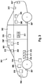
- Fig. 3 shows a possible embodiment of inventive system 301 for promoting a uniform driving style.
- System 301 comprises motor vehicle 302 as well as a multiplicity of further elements, for example covered by motor vehicle 302.
- These elements are camera sensors 303 in the form of a stereo camera, radar sensors 304 and 304 'in the form of a head-on Radar sensor and a rear radar sensor, electronic memory 305, which digital map material and is coupled to position determining means 306 in the form of GPS receiver on the data plane, wherein electronic memory 305 and position determining means 306 together fulfill the function of a route planner and route guide.
- system 301 comprises means for determining a longitudinal speed of the motor vehicle 307 and 307 'in the form of ABS speed sensors, passive safety means for protecting vehicle occupants 308 and 308' in the form of an airbag and a belt tensioner, means for determining a radius of curvature of a track section ahead of the motor vehicle 309 in the form of an electronic computing module, accelerator pedal 310, brake pedal 311, clutch pedal 312 and man-machine interface 319 in the form of a touch screen.
- the system comprises weather position sensors 313 and 313 'in the form of a rain sensor and an outside temperature sensor, friction coefficient estimation means 316 in the form of another electronic computing module, means for determining an anticipated lateral acceleration 309 which integrates into the electronic calculation module of the means for determining a radius of curvature 309 Since the electronic computing module has sufficient computing capacity for a plurality of uses, comparing means 309 for comparing the expected lateral acceleration with a fixed lateral acceleration limit and with a driver predetermined lateral acceleration limit, which also integrates into the electronic calculation module of the means for determining a radius of curvature 309 is means for optical, acoustic and haptic request 317, which in the form of a display, a connection to the public address system of motor vehicle 302 and one in the Lenkra d integrated vibration generator are executed and brake intervention means 318 in the form of an ESC system and means for engine drag reduction 314 in the form of an electronic throttle cable.
Landscapes
- Engineering & Computer Science (AREA)
- Mechanical Engineering (AREA)
- Transportation (AREA)
- Automation & Control Theory (AREA)
- Chemical & Material Sciences (AREA)
- Combustion & Propulsion (AREA)
- Human Computer Interaction (AREA)
- Physics & Mathematics (AREA)
- Mathematical Physics (AREA)
- Control Of Driving Devices And Active Controlling Of Vehicle (AREA)
- Traffic Control Systems (AREA)
- Radar, Positioning & Navigation (AREA)
- Remote Sensing (AREA)
- General Engineering & Computer Science (AREA)
- General Physics & Mathematics (AREA)
Description
Die Erfindung betrifft ein Verfahren zur Förderung eines gleichmäßigen Fahrstils gemäß Oberbegriff von Anspruch 1 und ein System zur Förderung eines gleichmäßigen Fahrstils gemäß Oberbegriff von Anspruch 11.The invention relates to a method for promoting a uniform driving style according to the preamble of claim 1 and a system for promoting a uniform driving style according to the preamble of
Im Stand der Technik ist bereits eine Vielzahl unterschiedlicher Sensorsysteme zur Umfelderfassung bekannt. Mittels dieser Sensorsysteme ist es beispielsweise möglich, Aussagen über den Straßenzustand zu treffen, den Abstand zu einem Vorausfahrzeug zu bestimmen und auch das Auftreten von Gefahrensituationen zu erkennen. Ebenso ist die Verwendung von globalen Satellitennavigationssystemen in Verbindung mit digitalem Kartenmaterial in Kraftfahrzeugen bekannt, beispielsweise zur Streckenführung oder auch zur Bewarnung des Fahrers, wenn dieser sich einer engen Kurve mit zu hoher Geschwindigkeit nähert. Schließlich ist es bekannt, zur Gefahrenabwendung autonome Eingriffe in die Fahrzeugsteuerung, insbesondere in die Fahrzeugbremsanlage, auf Basis der erfassten Umfeldsensordaten bzw. des digitalen Kartenmaterials auszuführen.In the prior art, a variety of different sensor systems for environment detection is already known. By means of these sensor systems, it is possible, for example, to make statements about the road condition, to determine the distance to a vehicle in front and also to detect the occurrence of dangerous situations. Likewise, the use of global satellite navigation systems in conjunction with digital map material in motor vehicles is known, for example, for routing or for the warning of the driver when it approaches a tight curve at too high a speed. Finally, it is known to carry out autonomous interventions in the vehicle control system, in particular in the vehicle brake system, on the basis of the detected surroundings sensor data or the digital map material for the purpose of averting danger.
In diesem Zusammenhang offenbart die
Aus der
In der unveröffentlichten
Nachteilig bei den aus dem Stand der Technik bekannten Verfahren ist es jedoch, dass die bekannten Eingriffe in die Fahrzeugsteuerung ausschließlich sicherheitsorientiert und ohne Berücksichtigung der Förderung oder zumindest Wahrung eines gleichmäßigen und flüssigen Fahrstils erfolgen.A disadvantage of the known from the prior art method, however, is that the known interventions in the vehicle control exclusively safety-oriented and take into account the promotion or at least maintaining a uniform and fluid driving style.
Die
Der Erfindung liegt daher die Aufgabe zugrunde, ein Verfahren vorzuschlagen, welches Eingriffe in die Fahrzeugsteuerung nicht ausschließlich sicherheitsorientiert durchführt.The invention is therefore based on the object to propose a method which performs interventions in the vehicle control not exclusively safety-oriented.
Diese Aufgabe wird erfindungsgemäß durch das Verfahren zur Förderung eines gleichmäßigen Fahrstils gemäß Anspruch 1 gelöst. Gemäß dem erfindungsgemäßen Verfahren zur Förderung eines gleichmäßigen Fahrstils, bei welchem eine Längsgeschwindigkeit eines Kraftfahrzeugs und ein Krümmungsradius eines dem Kraftfahrzeug vorausliegenden Streckenabschnitts bei Annäherung des Kraftfahrzeugs an den Streckenabschnitt bestimmt werden, wobei aus dem Krümmungsradius und der Längsgeschwindigkeit eine zu erwartende Querbeschleunigung beim Durchfahren des Streckenabschnitts bestimmt wird und diese mit einem fest vorgegebenen und mit einem vom Fahrer vorgebbaren Querbeschleunigungsgrenzwert verglichen wird erfolgt im Falle, dass die zu erwartende Querbeschleunigung größer als mindestens einer der Querbeschleunigungsgrenzwerte ist, mittels einer optischen und/oder akustischen und/oder haptischen Aufforderung an den Fahrer und/oder mittels eines autonomen Bremseneingriffs eine Verzögerung der Längsgeschwindigkeit, bis die zu erwartende Querbeschleunigung den geringeren der beiden Querbeschleunigungsgrenzwerte erreicht. Das erfindungsgemäße Verfahren zeichnet sich dadurch aus, dass im Falle, dass die zu erwartende Querbeschleunigung kleiner oder gleich dem geringeren der beiden Querbeschleunigungsgrenzwerte ist, mittels einer Motorschleppmomentreduktion die Verzögerung der Längsgeschwindigkeit reduziert wird.This object is achieved by the method for promoting a uniform driving style according to claim 1. According to the method according to the invention for promoting a uniform driving style in which a longitudinal speed of a motor vehicle and a radius of curvature of a road section ahead of the motor vehicle are determined when the motor vehicle approaches the track section, an anticipated lateral acceleration when passing through the track section being determined from the radius of curvature and the longitudinal speed and this is compared with a fixed predetermined and with a presettable by the driver lateral acceleration limit takes place in the event that the expected lateral acceleration is greater than at least one of the lateral acceleration limits, by means of an optical and / or acoustic and / or haptic request to the driver and / or by means of an autonomous brake intervention, a deceleration of the longitudinal speed until the expected lateral acceleration err the lower of the two lateral acceleration limit values err calibrates. The method according to the invention is characterized in that, in the event that the expected lateral acceleration is less than or equal to the lower of the two lateral acceleration limit values, by means of a Engine drag reduction the longitudinal speed deceleration is reduced.
Somit ermöglicht das erfindungsgemäße Verfahren nicht nur eine sowohl gleichmäßige als auch energiesparende und damit umweltschonende Fahrweise, sondern trägt auch zur Erhöhung der Fahrsicherheit bei, da ggf. ein autonomer Bremseneingriff zur Fahrzeugverzögerung vorgesehen ist, um eine kritische Querbeschleunigung beim Durchfahren des den Krümmungsradius aufweisenden Streckenabschnitts zu vermeiden.Thus, the method according to the invention not only allows a uniform as well as energy-saving and thus environmentally friendly driving, but also contributes to increasing driving safety, since possibly an autonomous braking intervention is provided for vehicle deceleration, to a critical lateral acceleration when driving through the section having the radius of curvature avoid.
Die im Sinne der Erfindung mit dem Begriff "zu erwartende Querbeschleunigung" bezeichnete physikalische Größe ist im einfachsten Fall diejenige Querbeschleunigung, welche sich rechnerisch aus dem Krümmungsradius und der aktuellen Längsgeschwindigkeit des Kraftfahrzeugs ergibt. Vorzugsweise können aber auch komplexere Modelle zugrunde gelegt werden, welche eine Vorhersage einer wahrscheinlichen Längsgeschwindigkeit zum Zeitpunkt des Durchfahrens des den Krümmungsradius aufweisenden Streckenabschnitts erlauben. In diesem Fall wird besonders bevorzugt die wahrscheinliche Längsgeschwindigkeit zur Bestimmung der zu erwartenden Querbeschleunigung herangezogen.In the simplest case, the physical variable referred to by the term "expected lateral acceleration" is that lateral acceleration which results mathematically from the radius of curvature and the actual longitudinal speed of the motor vehicle. Preferably, however, it is also possible to use more complex models which permit a prediction of a probable longitudinal speed at the time of passing through the section of road having the radius of curvature. In this case, the probable longitudinal speed is particularly preferably used to determine the expected lateral acceleration.
Sofern ausschließlich ein fest vorgegebener Querbeschleunigungsgrenzwert und kein vom Fahrer vorgegebener Querbeschleunigungsgrenzwert zur Verfügung steht, wird der fest vorgegebene Querbeschleunigungsgrenzwert vom erfindungsgemäßen Verfahren als geringerer der beiden Querbeschleunigungsgrenzwerte angenommen. Der vom Fahrer vorgegebener Querbeschleunigungsgrenzwert kann in diesem Fall z.B. auf unendlich gesetzt werden.If only a predefined lateral acceleration limit value and no lateral acceleration limit value prescribed by the driver are available, the fixedly specified lateral acceleration limit value is assumed by the method according to the invention to be lower than the two lateral acceleration limit values. In this case, the lateral acceleration limit value specified by the driver can be set to infinity, for example.
Der fest vorgegebene Querbeschleunigungsgrenzwert ist vorzugsweise nach Fahrsicherheitsaspekten derart gewählt, dass er ein Abkommen des Kraftfahrzeugs von der Fahrbahn bzw. ein Schleudern des Fahrzeugs aufgrund der für die zu erwartende Querbeschleunigung zu geringen Seitenführungskräfte der Fahrzeugreifen gerade noch verhindert. Somit ist in der Regel der fest vorgegebene Querbeschleunigungsgrenzwert größer als der vom Fahrer vorgebbaren Querbeschleunigungsgrenzwert. Besonders bevorzugt wird dem Fahrer nicht die Möglichkeit geboten, einen Querbeschleunigungsgrenzwert vorzugeben, der größer als der fest vorgegebene Querbeschleunigungsgrenzwert ist.The fixedly predetermined lateral acceleration limit value is preferably chosen according to driving safety aspects in such a way that it barely prevents an agreement of the motor vehicle from the roadway or a skidding of the vehicle due to the cornering forces of the vehicle tires that are too low for the expected lateral acceleration. As a result, the predefined lateral acceleration limit value is generally greater than the lateral acceleration limit value which can be predetermined by the driver. Particularly preferably, the driver is not offered the option of specifying a lateral acceleration limit which is greater than the predefined lateral acceleration limit value.
Bevorzugt ist es vorgesehen, dass der vom Fahrer vorgebbare Querbeschleunigungsgrenzwert mittels einer Mensch-Maschine-Schnittstelle vorgebbar ist, wobei der vom Fahrer vorgebbare Querbeschleunigungsgrenzwert indirekt über die Auswahl eines vom Fahrer bevorzugten Fahrstils vorgebbar ist. Daraus ergibt sich der Vorteil, dass der Fahrer nicht mit für ihn unverständlichen Zahlenwerten konfrontiert wird, deren Auswahl und Vorgabe als Querbeschleunigungsgrenzwert in der Regel zu einem für die meisten Fahrer nicht vorhersehbaren Ergebnis führt, da diese in der Regel nicht die notwendige technische Vorbildung besitzen, welche zur Beurteilung eines Querbeschleunigungswerts notwendig ist. Stattdessen werden dem Fahrer Auswahlmöglichkeiten mit für ihn nachvollziehbaren Begriffen vorgeschlagen, wobei die Auswahl eines der Begriffe automatisch die Auswahl und Vorgabe eines zugehörigen Querbeschleunigungsgrenzwerts nach sich zieht. Beispiele für eine derartige indirekte Auswahl des Querbeschleunigungsgrenzwerts über einen für den Fahrer verständlichen Begriff sind etwa die Vorgaben "sportlich", "normal" oder "eco". Der Vorgabe "sportlich" entspricht dabei bevorzugt ein Querbeschleunigungswert von 9 m/s2, der Vorgabe "normal" entspricht bevorzugt ein Querbeschleunigungswert von 4 m/s2 und der Vorgabe "eco" entspricht bevorzugt ein Querbeschleunigungswert von 2,5 m/s2.It is preferably provided that the lateral acceleration limit value predeterminable by the driver can be predetermined by means of a man-machine interface, wherein the lateral acceleration limit value predeterminable by the driver can be predetermined indirectly via the selection of a driving style preferred by the driver. This results in the advantage that the driver is not confronted with numerical values which are incomprehensible to him, whose selection and specification as a lateral acceleration limit usually leads to a result which is unforeseeable for most drivers, since these generally do not have the necessary technical training, which is necessary for the evaluation of a lateral acceleration value. Instead, the driver is offered choices with terms that are comprehensible to him, with the selection of one of the terms automatically entailing the selection and specification of an associated lateral acceleration limit. Examples of such an indirect selection of the lateral acceleration limit value over a term that can be understood by the driver are, for example, the specifications "sporty", "normal" or "eco". The default "sporty" preferably corresponds to a lateral acceleration value of 9 m / s 2 , the default "normal" preferably corresponds to a lateral acceleration value of 4 m / s 2 and the default "eco" preferably corresponds to a lateral acceleration value of 2.5 m / s 2 .
Die Mensch-Maschine-Schnittstelle kann bevorzugt als Display, besonders bevorzugt als Touch-Screen, als Tastenfeld oder in Form eines einzelnen Tasters ausgebildet sein.The man-machine interface can preferably be designed as a display, particularly preferably as a touch screen, as a keypad or in the form of a single button.
Zweckmäßigerweise ist es vorgesehen, dass ein Ausführungsstart des Verfahrens erfolgt, wenn der Fahrer keine Pedalbetätigung vornimmt und dass eine Ausführungsbeendigung des Verfahrens erfolgt, wenn der Fahrer eine Pedalbetätigung vornimmt. Eine Situation, in welcher der Fahrer keine Pedalbetätigung vornimmt, liegt in der Regel dann vor, wenn der Fahrer beim Annähern an eine Kurve oder an ein vorausfahrendes Fahrzeug kurzfristig unschlüssig ist, ob eine Reduzierung der Längsgeschwindigkeit notwendig oder sinnvoll ist. In dieser Phase der Unschlüssigkeit des Fahrers kann nun ein Ausführungsstart des erfindungsgemäßen Verfahrens erfolgen, wobei dem Fahrer insbesondere optisch angezeigt wird, dass das Verfahren gestartet wurde und der Fahrer somit die weitere Steuerung der Längsgeschwindigkeit nicht selbständig vornehmen muss. Ein weiterer Vorteil ist, dass das Verfahren nicht gestartet wird, während der Fahrer aktiv eine Eingabe zur Steuerung der Längsgeschwindigkeit vornimmt. Eine Überlagerung von Steuereingaben bzw. gar eine Übersteuerung des Fahrers gegen dessen Willen wird somit vermieden. Indem eine Ausführungsbeendigung des Verfahrens erfolgt, wenn der Fahrer eine Pedalbetätigung vornimmt, wird zudem gewährleistet, dass der Fahrer jederzeit wieder die volle Kontrolle über das Fahrzeug übernehmen kann.Appropriately, it is provided that an execution start of the method takes place when the driver makes no pedal operation and that an execution completion of the method takes place when the driver performs a pedal operation. A situation in which the driver makes no pedaling is usually present when the driver is briefly undecided when approaching a curve or to a vehicle ahead, whether a reduction in the longitudinal speed is necessary or useful. In this phase of the indecision of the driver, an execution start of the method according to the invention can now take place, wherein the driver is visually indicated in particular that the method has been started and the driver thus does not have to make the further control of the longitudinal speed independently. Another advantage is that the method is not started while the driver is actively making an input to control the longitudinal speed. A superposition of control inputs or even an override of the driver against his will is thus avoided. By completing the execution of the method, when the driver performs a pedal operation, it is also ensured that the driver can always take full control of the vehicle again.
Weiterhin ist es bevorzugt, dass die Bestimmung des Krümmungsradius mittels Kamerasensorik und/oder mittels Radarsensorik und/oder mittels Lidarsensorik und/oder mittels Lasersensorik und/oder mittels digitalem Kartenmaterial und einer Positionsbestimmung des Kraftfahrzeugs erfolgt. Die genannten Sensorikgattungen sind zur Umfelderfassung einschließlich der Bestimmung eines Krümmungsradius bei einer Annäherung des Fahrzeugs an den den Krümmungsradius aufweisenden Streckenabschnitt geeignet. Sofern mehrere der genannten Sensorikgattungen im Kraftfahrzeug zur Verfügung stehen, kann die Bestimmung eines Krümmungsradius redundant und zuverlässiger ausgeführt werden. Eine Bestimmung des Krümmungsradius mittels digitalem Kartenmaterial und einer Positionsbestimmung des Kraftfahrzeugs bietet zudem den Vorteil, dass ein Großteil der aktuellen Kraftfahrzeuge bereits mit Positionsbestimmungseinrichtungen, z.B. auf Basis von GPS, und mit digitalem Kartenmaterial zur Streckenführung ausgestattet sind. Ein kostenverursachender zusätzlicher Austattungsaufwand ist in diesem Fall nicht notwendig.Furthermore, it is preferable for the determination of the radius of curvature to be effected by means of camera sensors and / or by means of radar sensors and / or by means of lidar sensors and / or by means of laser sensors and / or by means of digital map material and a position determination of the motor vehicle takes place. The mentioned types of sensors are suitable for detecting the surroundings including the determination of a radius of curvature when the vehicle approaches the road section having the radius of curvature. If a plurality of said types of sensor are available in the motor vehicle, the determination of a radius of curvature can be carried out redundantly and reliably. A determination of the radius of curvature by means of digital map material and a position determination of the motor vehicle also offers the advantage that a large part of the current motor vehicles are already equipped with position-determining devices, eg based on GPS, and with digital map material for routing. A cost-causing additional Ausstattungsaufwand is not necessary in this case.
Insbesondere ist es bevorzugt, dass die Positionsbestimmung des Kraftfahrzeugs mittels eines globalen Satellitennavigationssystems und/oder mittels eines Karteneinpassungsverfahrens erfolgt. Viele der aktuellen Kraftfahrzeuge verfügen bereits über Positionsbestimmungseinrichtungen auf Basis von z.B. GPS, was die Implementierungskosten für das erfindungsgemäße Verfahren in diese Kraftfahrzeuge gering hält. Die Positionsbestimmung mittels eines Karteneinpassungsverfahrens ermöglicht es zusätzlich oder alternativ, erfasste Umfelddaten, wie z.B. eine Tunneleinfahrt, eine scharfe Kurve oder eine charakteristische Straßenkreuzung, mit digitalem Kartenmaterial, welches ebenfalls Umfelddaten beschreibt, abzugleichen und die aktuelle Position des Kraftfahrzeugs über den Abgleich in die Kartendaten einzupassen.In particular, it is preferred that the position determination of the motor vehicle is carried out by means of a global navigation satellite system and / or by means of a card adaptation method. Many of the current motor vehicles already have positioning devices based on e.g. GPS, which keeps the implementation costs for the inventive method in these vehicles low. The position determination by means of a card fitting method additionally or alternatively allows detected environment data, such as e.g. a tunnel entrance, a sharp curve or a characteristic intersection, with digital map material, which also describes environment data to match and fit the current position of the motor vehicle on the balance in the map data.
Außerdem ist es zweckmäßig, dass die durch den autonomen Bremseneingriff erfolgte Verzögerung der Längsgeschwindigkeit einen vorgegebenen Verzögerungsgrenzwert, insbesondere 3 m/s2, nicht übersteigt. Dadurch wird vermieden, dass das erfindungsgemäße Verfahren durch einen scharfen und ggf. plötzlichen Verzögerungsvorgang einen Auffahrunfall provoziert. Sofern eine stärkere Verzögerung notwendig erscheint als sie der vorgegebene Verzögerungsgrenzwert zulässt, kann eine entsprechende Warnung bzw. Aufforderung an den Fahrer ausgegeben werden. Der Fahrer kann dann nach einer Beurteilung der vorliegenden Situation eine entsprechend starke Verzögerung einstellen.In addition, it is expedient that the delay of the longitudinal speed, which was effected by the autonomous brake intervention does not exceed a predetermined delay limit, in particular 3 m / s 2 . This avoids that the inventive method provoked by a sharp and possibly sudden deceleration a rear-end collision. If a greater delay appears necessary than the predetermined deceleration limit value allows, a corresponding warning or request can be issued to the driver. The driver can then adjust to a judgment of the present situation, a correspondingly strong delay.
Außerdem ist es vorteilhaft, dass aus einer Mehrzahl von möglichen vom Kraftfahrzeug zu durchfahrenden Streckenabschnitten der vorausliegende Streckenabschnitt mittels Daten eines Streckenplaners ausgewählt wird. Somit kann auch im Falle des Annäherns des Kraftfahrzeugs an eine Streckengabelung bereits im Voraus sicher erkannt werden, welcher Streckenabschnitt vom Kraftfahrzeug durchfahren werden wird, was wiederum die Bestimmung des Krümmungsradius dieses Streckenabschnitts im Voraus ermöglicht.In addition, it is advantageous that, from a plurality of possible road sections to be traveled by the motor vehicle, the route section lying ahead is selected by means of data from a route planner. Thus, even in the case of approaching the motor vehicle to a track crotch, it can be reliably detected in advance which section of the track will be traversed by the motor vehicle, which in turn enables the determination of the radius of curvature of this section in advance.
Weiterhin ist es vorteilhaft, dass bei Erkennen auf ein Überschreiten des Querbeschleunigungsgrenzwerts, insbesondere des fest vorgegebenen Querbeschleunigungsgrenzwerts, beim Durchfahren des den Krümmungsradius aufweisenden Streckenabschnitts passive Sicherheitsmittel zum Schutz von Fahrzeuginsassen aktiviert werden, insbesondere ein oder mehrere Gurtstraffer aktiviert werden. Ein Überschreiten des Querbeschleunigungsgrenzwerts, insbesondere des fest vorgegebenen Querbeschleunigungsgrenzwerts, kann ein Hinweis auf eine kurzfristig eintretende Gefahrensituation sein, da etwa die Seitenführungskräfte der Fahrzeugreifen zu gering für die zu erwartende Querbeschleunigung sein können. Durch vorausschauendes Aktivieren von passiven Sicherheitsmittel, wird das Verletzungsrisiko für den Fahrer und evtl. weitere Fahrzeuginsassen in einer derartigen Situation verringert.Furthermore, it is advantageous that upon detection of an exceeding of the transverse acceleration limit value, in particular of the fixed predetermined lateral acceleration limit value, when driving through the section having the radius of curvature passive safety means for protecting vehicle occupants are activated, in particular one or more belt tensioners are activated. Exceeding the lateral acceleration limit value, in particular the fixedly predetermined lateral acceleration limit value, can be an indication of a danger situation which occurs at short notice since, for example, the cornering forces of the vehicle tires may be too low for the anticipated lateral acceleration. By proactive activation of passive security means, the risk of injury to the driver and possibly other vehicle occupants is reduced in such a situation.
Bevorzugt ist es vorgesehen, dass eine Reibwertschätzung durchgeführt wird, wobei die die Reibwertschätzung einer Vorgabe des fest vorgegebenen Querbeschleunigungsgrenzwerts zugrunde gelegt wird. Die Reibwertschätzung kann z.B. aus der Wetterlage bzw. einer zuvor ausgeführten ABS- oder ESC-Regelung erfolgen. So ist etwa bei Regen, insbesondere bei tiefen Temperaturen, mit einem deutlich verringerten Reibwert zu rechnen. Diesem Umstand kann Rechnung getragen werden, indem der fest vorgegebene Querbeschleunigungsgrenzwert vom erfindungsgemäßen Verfahren selbsttätig angepasst wird.It is preferably provided that a coefficient of friction estimation is carried out, wherein the coefficient of friction estimation is based on a specification of the predefined lateral acceleration limit value. The coefficient of friction estimation may e.g. from the weather or a previously performed ABS or ESC control. For example, in the case of rain, especially at low temperatures, a significantly reduced coefficient of friction is to be expected. This circumstance can be taken into account by the fixed predetermined lateral acceleration limit value is automatically adjusted by the inventive method.
Außerdem ist es vorgesehen, dass mittels der Kamerasensorik und/oder mittels der Radarsensorik und/oder mittels der Lidarsensorik und/oder mittels der Lasersensorik ein dem Kraftfahrzeug vorausfahrendes Fahrzeug erkannt wird und ein Abstand und eine Differenzgeschwindigkeit zu diesem bestimmt werden, wobei im Falle, dass das Kraftfahrzeug sich dem vorausfahrenden Fahrzeug annähert und dabei voraussichtlich einen verkehrsüblichen Sicherheitsabstand unterschreiten wird mittels einer optischen und/oder akustischen und/oder haptischen Aufforderung an den Fahrer oder mittels eines autonomen Bremseneingriffs eine Verzögerung der Längsgeschwindigkeit erfolgt, so dass das Kraftfahrzeug den verkehrsüblichen Sicherheitsabstand zum vorausfahrenden Fahrzeug voraussichtlich nicht unterschreiten wird und wobei im Falle, dass das Kraftfahrzeug sich dem vorausfahrenden Fahrzeug nicht weiter annähert und/oder sich der Abstand zum vorausfahrenden Fahrzeug vergrößert, mittels einer Motorschleppmomentreduktion die Längsverzögerung reduziert wird. Daraus ergibt sich der Vorteil, dass das erfindungsgemäße Verfahren auch bei Erkennen eines dem Kraftfahrzeug vorausfahrenden Fahrzeugs vorteilhaft zur Anwendung kommt. Dies stellt im Sinne der Erfindung eine dem Durchfahren eines einen Krümmungsradius aufweisenden Streckenabschnitts analoge Situation dar. Die Analogie beider Situationen besteht darin, dass in beiden Fällen vom Fahrer abgeschätzt werden muss, mit welchem Anfahrverhalten er sich dem den Krümmungsradius aufweisenden Streckenabschnitt bzw. dem vorausfahrenden Fahrzeug annähern will. Hierbei kann das erfindungsgemäße Verfahren zur Förderung eines gleichmäßigen Fahrstils eine Unterstützung sein.In addition, it is provided that by means of the camera sensor system and / or by means of the radar sensor system and / or by means of the Lidarsensorik and / or by means of the laser sensor, a vehicle ahead of the vehicle is detected and a distance and a differential speed are determined to this, wherein in the event that the motor vehicle approaches the vehicle in front and is likely to fall below a customary safety distance by means of a visual and / or acoustic and / or haptic request to the driver or by means of an autonomous braking intervention, a deceleration of the longitudinal speed, so that the motor vehicle the usual safety distance to the vehicle ahead Presumably the vehicle will not fall below and in the event that the motor vehicle does not approach the preceding vehicle and / or the distance to the vehicle in front increases, by means of a Motorschleppm omentreduktion the longitudinal delay is reduced. This results in the advantage that the method according to the invention is also advantageous when detecting a vehicle driving ahead of the motor vehicle Application comes. In the sense of the invention, this represents a situation analogous to driving through a section of road having a radius of curvature. The analogy of both situations is that in both cases it must be estimated by the driver with which starting behavior he / she has the section of road or the preceding vehicle having the radius of curvature wants to approximate. In this case, the method according to the invention for promoting a uniform driving style can be a support.
Die vorliegende Erfindung betrifft weiterhin ein System zur Förderung eines gleichmäßigen Fahrstils, welches ein Kraftfahrzeug und Kamerasensorik und/oder Radarsensorik und/oder Lidarsensorik und/oder Lasersensorik und/oder Positionsbestimmungsmittel und/oder einen digitales Kartenmaterial umfassenden elektronischen Speicher umfasst. Weiterhin umfasst das System Mittel zur Bestimmung einer Längsgeschwindigkeit des Kraftfahrzeugs und passive Fahrzeuginsassensicherheitsmittel und Mittel zur Bestimmung eines Krümmungsradius eines dem Kraftfahrzeug vorausliegenden Streckenabschnitts sowie ein Fahrpedal und ein Bremspedal zum Einstellen einer Längsgeschwindigkeit des Kraftfahrzeugs. Das System umfasst außerdem Wetterlagesensorik und Mittel zur Reibwertschätzung sowie Mittel zur Bestimmung einer zu erwartenden Querbeschleunigung beim Durchfahren des Streckenabschnitts und Vergleichsmittel zum Vergleichen der zu erwartenden Querbeschleunigung mit einem fest vorgegebenen und mit einem vom Fahrer vorgebbaren Querbeschleunigungsgrenzwert. Schließlich umfasst das System Mittel zur optischen und/oder akustischen und/oder haptischen Aufforderung an den Fahrer zur Verzögerung der Längsgeschwindigkeit und/oder Bremseneingriffsmittel zur autonomen Verzögerung der Längsgeschwindigkeit und Mittel zur Motorschleppmomentreduktion. Das System zeichnet sich dadurch aus dass es das erfindungsgemäße Verfahren ausführt. Das erfindungsgemäße System umfasst somit alle zur Ausführung des erfindungsgemäßen Verfahrens notwendigen Mittel und führt durch die Ausführung des erfindungsgemäßen Verfahrens zu den bereits beschriebenen Vorteilen.The present invention further relates to a system for promoting a uniform driving style, which comprises a motor vehicle and camera sensors and / or radar sensors and / or Lidarsensorik and / or laser sensor and / or position determining means and / or a digital map material comprising electronic memory. Furthermore, the system comprises means for determining a longitudinal speed of the motor vehicle and passive vehicle occupant safety means and means for determining a radius of curvature of a road section ahead of the motor vehicle and an accelerator pedal and a brake pedal for adjusting a longitudinal speed of the motor vehicle. The system also includes weather position sensors and means for friction coefficient estimation and means for determining an expected lateral acceleration when driving through the track section and comparing means for comparing the expected lateral acceleration with a fixed predetermined and with a driver predetermined transverse acceleration limit. Finally, the system comprises means for visual and / or acoustic and / or haptic request to the driver for deceleration of the longitudinal speed and / or brake intervention means for autonomous deceleration of the longitudinal speed and means for engine drag torque reduction. The system is characterized by this from that it carries out the method according to the invention. The system according to the invention thus comprises all means necessary for carrying out the method according to the invention and, by carrying out the method according to the invention, leads to the already described advantages.
Die Wetterlagesensorik kann dabei z.B. als Regensensor bzw. Temperatursensor ausgeführt sein bzw. einen Radioempfänger oder sonstigen geeigneten kanellosen Datenempfänger zum Empfang von Wetterdaten umfassen.The weather position sensor can, for example, be designed as a rain sensor or temperature sensor or include a radio receiver or other suitable kanellosen data receiver for receiving weather data.
Weitere bevorzugte Ausführungsformen ergeben sich aus den Unteransprüchen und der nachfolgenden Beschreibung eines Ausführungsbeispiels an Hand von Figuren.Further preferred embodiments will become apparent from the subclaims and the following description of an embodiment with reference to figures.
Es zeigen
- Fig. 1
- ein Kraftfahrzeug, das sich einem einen Krümmungsradius aufweisenden Streckenabschnitt nähert,
- Fig. 2
- ein Kraftfahrzeug, das sich einem dem Kraftfahrzeug vorausfahrenden Fahrzeug nähert und
- Fig. 3
- einen beispielhaften Aufbau eines erfindungsgemäßen Systems.
- Fig. 1
- a motor vehicle approaching a section of road having a radius of curvature,
- Fig. 2
- a motor vehicle approaching a vehicle ahead of the motor vehicle and;
- Fig. 3
- an exemplary structure of a system according to the invention.
In
Claims (11)
- Method for promoting a uniform driving style,- with which a longitudinal speed of a motor vehicle (11, 21, 302) and a radius of curvature of a route segment (13) ahead of the motor vehicle (11, 21, 302) are determined when the motor vehicle is approaching the route segment (13),- wherein a lateral acceleration to be expected when driving through the route segment (13) is determined from the radius of curvature and the longitudinal speed and is compared with a fixed specified lateral acceleration limit value and with a lateral acceleration limit value specifiable by the driver and- wherein in the case in which the lateral acceleration to be expected is greater than at least one of the lateral acceleration limit values, a deceleration of the longitudinal speed is carried out by means of a visual and/or audible and/or haptic request to the driver and/or by means of an autonomous braking intervention until the lateral acceleration to be expected reaches the lower of the two lateral acceleration limit values, characterized in that in the case in which the lateral acceleration to be expected is less than or equal to the lower of the two lateral acceleration limit values, the deceleration of the longitudinal speed is reduced by means of an engine drag torque reduction.
- Method according to Claim 1,
characterized in that
the lateral acceleration limit value specifiable by the driver can be specified by means of a man-machine interface (319), wherein the lateral acceleration limit value specifiable by the driver can be specified indirectly by the selection of a driving style preferred by the driver. - Method according to at least one of Claims 1 and 2,
characterized in that
implementation of the method is started if the driver does not carry out a pedal operation and termination of implementation of the method takes place if the driver carries out a pedal operation. - Method according to at least one of Claims 1 through 3,
characterized in that
the determination of the radius of curvature takes place by means of camera sensors (303) and/or by means of radar sensors (304, 304') and/or by means of lidar sensors and/or by means of laser sensors and/or by means of digital map material (305) and a determination of the position of the motor vehicle. - Method according to Claim 4,
characterized in that
the determination of the position of the motor vehicle takes place by means of a global satellite navigation system and/or by means of a map matching process. - Method according to at least one of Claims 1 through 5,
characterized in that
the deceleration of the longitudinal speed achieved by the autonomous braking intervention does not exceed a specified deceleration limit value, in particular 3 m/s2. - Method according to at least one of Claims 1 through 6,
characterized in that
the segment of route (13) ahead is selected from a number of possible route segments (13) to be driven through by the motor vehicle by means of the data of a route planner (305, 306). - Method according to at least one of Claims 1 through 7,
characterized in that
on detecting that the lateral acceleration limit value is exceeded, in particular the fixed specified lateral acceleration limit value, when driving through the route segment comprising the radius of curvature (13), passive safety means for the protection of vehicle occupants (308, 308') are activated, in particular one or a plurality of belt tensioners is/are activated. - Method according to at least one of Claims 1 through 8,
characterized in that
an estimation of the coefficient of friction is carried out, wherein the estimate of the coefficient of friction is used as a basis for a specification of the fixed specified lateral acceleration limit value. - Method according to at least one of Claims 1 through 9,
characterized in that
by means of the camera sensors (303) and/or by means of the radar sensors (304, 304') and/or by means of the lidar sensors and/or by means of the laser sensors a vehicle (22) ahead of the motor vehicle (11, 21, 302) is detected and a distance to and a speed difference relative to said vehicle are determined, wherein in the case in which the motor vehicle (11, 21, 302) is approaching the vehicle ahead (22) and during this it is likely that the distance will fall below a normal traffic safety distance, a deceleration of the longitudinal speed is carried out by means of a visual and/or audible and/or haptic request to the driver or by means of an autonomous braking intervention, so that the motor vehicle (11, 21, 302) is not likely to fall below the normal traffic safety distance to the vehicle ahead (22) and wherein in the case in which the motor vehicle (11, 21, 302) is no longer approaching the vehicle ahead (22) and/or the distance to the vehicle ahead (22) is increasing, the longitudinal acceleration is reduced by means of an engine drag torque reduction. - System for promoting a uniform driving style (301), comprising a motor vehicle (11, 21, 302) and camera sensors (303) and/or radar sensors (304, 304') and/or lidar sensors and/or laser sensors and/or position determination means (306) and/or an electronic memory (305) comprising digital map material and means for the determination of a longitudinal speed (307, 307') of the motor vehicle (11, 21, 302) and passive safety means for the protection of vehicle occupants (308, 308') and means for the determination of a radius of curvature (309) of a route segment ahead of the motor vehicle (13) and a gas pedal (310) and a brake pedal (311) for adjusting a longitudinal speed of the motor vehicle and a man-machine interface (319) and weather condition sensors (313, 313') and means for the estimation of the coefficient of friction (316) and means for the determination of a lateral acceleration to be expected (309) when driving through the route segment (13) and comparison means (300) for comparing the lateral acceleration to be expected with a fixed specified lateral acceleration limit value and with a lateral acceleration limit value specifiable by the driver and means for making a visual and/or audible and/or haptic request (317) to the driver for deceleration of the longitudinal speed and/or braking intervention means (318) for the autonomous deceleration of the longitudinal speed and means for engine drag torque reduction (314),
characterized in that
the system implements a method according to at least one of Claims 1 through 10.
Applications Claiming Priority (2)
| Application Number | Priority Date | Filing Date | Title |
|---|---|---|---|
| DE102012215100.1A DE102012215100A1 (en) | 2012-08-24 | 2012-08-24 | Method and system for promoting a uniform driving style |
| PCT/EP2013/067570 WO2014029882A1 (en) | 2012-08-24 | 2013-08-23 | Method and system for promoting a uniform driving style |
Publications (2)
| Publication Number | Publication Date |
|---|---|
| EP2888143A1 EP2888143A1 (en) | 2015-07-01 |
| EP2888143B1 true EP2888143B1 (en) | 2016-10-12 |
Family
ID=49085006
Family Applications (1)
| Application Number | Title | Priority Date | Filing Date |
|---|---|---|---|
| EP13756066.0A Active EP2888143B1 (en) | 2012-08-24 | 2013-08-23 | Method and system for promoting a uniform driving style |
Country Status (6)
| Country | Link |
|---|---|
| US (1) | US9399450B2 (en) |
| EP (1) | EP2888143B1 (en) |
| KR (1) | KR102119917B1 (en) |
| CN (1) | CN104736409B (en) |
| DE (1) | DE102012215100A1 (en) |
| WO (1) | WO2014029882A1 (en) |
Families Citing this family (33)
| Publication number | Priority date | Publication date | Assignee | Title |
|---|---|---|---|---|
| US9878693B2 (en) | 2004-10-05 | 2018-01-30 | Vision Works Ip Corporation | Absolute acceleration sensor for use within moving vehicles |
| US7239953B2 (en) | 2004-10-05 | 2007-07-03 | Vision Works, Llc | Absolute acceleration sensor for use within moving vehicles |
| US8954251B2 (en) | 2004-10-05 | 2015-02-10 | Vision Works Ip Corporation | Absolute acceleration sensor for use within moving vehicles |
| US9327726B2 (en) | 2004-10-05 | 2016-05-03 | Vision Works Ip Corporation | Absolute acceleration sensor for use within moving vehicles |
| US9371002B2 (en) | 2013-08-28 | 2016-06-21 | Vision Works Ip Corporation | Absolute acceleration sensor for use within moving vehicles |
| US9855986B2 (en) | 2013-08-28 | 2018-01-02 | Vision Works Ip Corporation | Absolute acceleration sensor for use within moving vehicles |
| CN103777637B (en) * | 2014-02-13 | 2016-07-06 | 苏州工业园区艾吉威自动化设备有限公司 | Areflexia plate Laser Self navigation AGV dolly and air navigation aid thereof |
| SE1450601A1 (en) | 2014-05-21 | 2015-11-22 | Scania Cv Ab | Procedure and system for adapting a vehicle's performance on a roadway in conjunction with cornering |
| JP6007214B2 (en) * | 2014-08-08 | 2016-10-12 | 本田技研工業株式会社 | Braking force control device for saddle riding type vehicle |
| FR3029878B1 (en) * | 2014-12-16 | 2017-01-13 | Michelin & Cie | METHOD FOR PREDICTING THE SPEED OF A DRIVER AT THE STEERING WHEEL OF A VEHICLE |
| DE102015206501A1 (en) * | 2015-04-13 | 2016-10-13 | Bayerische Motoren Werke Aktiengesellschaft | Method for operating a vehicle and vehicle |
| KR102500704B1 (en) * | 2016-04-19 | 2023-02-16 | 주식회사 에이치엘클레무브 | Apparatus and method for controlling automatic driving of vehicle |
| DE102016208675A1 (en) * | 2016-05-19 | 2017-11-23 | Lucas Automotive Gmbh | Method for determining a safe speed at a future waypoint |
| US10310055B2 (en) * | 2016-06-23 | 2019-06-04 | GM Global Technology Operations LLC | Dynamic adjustment of radar parameters |
| DE102016120166A1 (en) * | 2016-10-24 | 2018-04-26 | Connaught Electronics Ltd. | Controlling a vehicle depending on the environment |
| CN106740868B (en) * | 2016-12-30 | 2019-03-29 | 东软集团股份有限公司 | A kind of method, apparatus and equipment of speed planning |
| DE102017000608A1 (en) * | 2017-01-24 | 2018-07-26 | Man Truck & Bus Ag | Method for operating a vehicle, in particular a utility vehicle |
| CN106828503B (en) * | 2017-02-15 | 2018-11-30 | 武汉理工大学 | A kind of operator brake behavior and state real-time identification method |
| CA3073798C (en) * | 2017-08-24 | 2021-05-04 | Nissan Motor Co., Ltd. | Method and device for controlling travel of drive-assisted vehicle |
| GB201715702D0 (en) * | 2017-09-28 | 2017-11-15 | Jaguar Land Rover Ltd | Method and apparatus for controlling electric machines |
| CN109649377B (en) * | 2017-10-11 | 2022-04-08 | 宇通客车股份有限公司 | Rollover early warning control method and system |
| KR102452551B1 (en) * | 2017-11-01 | 2022-10-07 | 현대자동차주식회사 | Apparatus for limiting lateral acceleration, system having the same and method thereof |
| DE102017221968A1 (en) * | 2017-12-05 | 2019-06-19 | Volkswagen Aktiengesellschaft | Method for operating a steering device and steering device |
| WO2019167729A1 (en) * | 2018-02-27 | 2019-09-06 | 本田技研工業株式会社 | Rideable mobile body |
| EP3647143B1 (en) | 2018-11-01 | 2023-08-16 | Zenuity AB | Method and arrangement for continous curve speed adjustment for a road vehicle |
| IT201800010456A1 (en) * | 2018-11-20 | 2020-05-20 | Fiat Ricerche | ELECTRONIC PREVENTIVE CHECK OF THE DRIVING STABILITY OF A MOTOR VEHICLE |
| US10852746B2 (en) * | 2018-12-12 | 2020-12-01 | Waymo Llc | Detecting general road weather conditions |
| CN110126760B (en) * | 2019-04-10 | 2021-07-16 | 百度在线网络技术(北京)有限公司 | Method, apparatus, device and medium for driving control of vehicle |
| CN113548036B (en) * | 2020-04-17 | 2023-12-01 | 广州汽车集团股份有限公司 | Engine output torque adjusting method, system and control equipment thereof |
| US11964691B2 (en) * | 2020-08-17 | 2024-04-23 | Magna Electronics Inc. | Vehicular control system with autonomous braking |
| DE112020007528T5 (en) | 2020-11-24 | 2023-08-10 | Dr. Ing. H.C. F. Porsche Aktiengesellschaft | Device and method for driving monitoring |
| CN113071489A (en) * | 2021-04-30 | 2021-07-06 | 宝能(广州)汽车研究院有限公司 | Vehicle running control method and device, vehicle-mounted electronic equipment and readable storage medium |
| FR3132260B1 (en) * | 2022-01-28 | 2023-12-15 | Psa Automobiles Sa | Method and system for managing the speed of a motor vehicle in a bend |
Family Cites Families (19)
| Publication number | Priority date | Publication date | Assignee | Title |
|---|---|---|---|---|
| JP3167993B2 (en) * | 1999-09-21 | 2001-05-21 | 富士重工業株式会社 | Road shape estimation device and curve entry control device using the same |
| DE10225892A1 (en) * | 2002-06-11 | 2004-01-08 | Robert Bosch Gmbh | Method and device for limiting the cornering speed |
| DE10242124B4 (en) * | 2002-09-11 | 2009-12-10 | Robert Bosch Gmbh | Method and device for adjusting the engine torque of a single-track motor vehicle |
| DE10311192A1 (en) * | 2003-03-12 | 2004-09-23 | Robert Bosch Gmbh | Device and procedure for the speed control of e.g. motor vehicle, has speed governor measuring object for identified objects using radar |
| KR101206320B1 (en) | 2004-10-29 | 2012-11-30 | 콘티넨탈 테베스 아게 운트 코. 오하게 | Process for enhancing the safety and/or comfort of a motor vehicle |
| JP4762528B2 (en) | 2004-11-10 | 2011-08-31 | 本田技研工業株式会社 | Vehicle travel safety device |
| DE102005033995A1 (en) | 2005-07-21 | 2007-02-01 | Dr.Ing.H.C. F. Porsche Ag | Method and device for controlling a yawing moment actuator in a motor vehicle |
| DE102005040791A1 (en) * | 2005-08-29 | 2007-03-01 | Robert Bosch Gmbh | Adaptive cruise control system operating state signaling method, for motor vehicle driver, involves causing modulation of longitudinal acceleration of vehicle by change of torque, which is given by internal combustion engine of vehicle |
| JP4742818B2 (en) | 2005-11-07 | 2011-08-10 | 日産自動車株式会社 | Vehicle deceleration control device |
| DE102007031542A1 (en) | 2007-07-06 | 2009-01-08 | Bayerische Motoren Werke Aktiengesellschaft | Cruise control for motor vehicles |
| US7774121B2 (en) | 2007-07-31 | 2010-08-10 | Gm Global Technology Operations, Inc. | Curve speed control system with adaptive map preview time and driving mode selection |
| JP2009101830A (en) * | 2007-10-23 | 2009-05-14 | Toyota Motor Corp | Control device for vehicle |
| DE102009041580A1 (en) | 2008-10-21 | 2010-04-22 | Continental Teves Ag & Co. Ohg | Method for foresighted warning of curves, involves detecting curve progress by peripheral sensor of vehicle, and comparing detected curve progress with digital card information based curve progress |
| DE102009000397A1 (en) * | 2009-01-23 | 2010-07-29 | Robert Bosch Gmbh | Method for triggering an automatic braking intervention before curves |
| DE102011102435A1 (en) * | 2011-05-25 | 2012-11-29 | Audi Ag | Method for operating a longitudinal driver assistance system and motor vehicle |
| CN103813950B (en) | 2011-07-19 | 2017-03-08 | 大陆-特韦斯贸易合伙股份公司及两合公司 | Method for improving riding stability |
| KR101504252B1 (en) * | 2013-11-28 | 2015-03-19 | 현대모비스 주식회사 | System for controlling speed of vehicle on curved road and method thereof |
| SE1450601A1 (en) * | 2014-05-21 | 2015-11-22 | Scania Cv Ab | Procedure and system for adapting a vehicle's performance on a roadway in conjunction with cornering |
| SE539444C2 (en) * | 2014-05-21 | 2017-09-26 | Scania Cv Ab | Procedure and system for safe driving of a vehicle during cornering |
-
2012
- 2012-08-24 DE DE102012215100.1A patent/DE102012215100A1/en not_active Withdrawn
-
2013
- 2013-08-23 EP EP13756066.0A patent/EP2888143B1/en active Active
- 2013-08-23 US US14/422,521 patent/US9399450B2/en active Active
- 2013-08-23 WO PCT/EP2013/067570 patent/WO2014029882A1/en active Application Filing
- 2013-08-23 KR KR1020157007369A patent/KR102119917B1/en active IP Right Grant
- 2013-08-23 CN CN201380055276.3A patent/CN104736409B/en active Active
Also Published As
| Publication number | Publication date |
|---|---|
| DE102012215100A1 (en) | 2014-02-27 |
| CN104736409A (en) | 2015-06-24 |
| US20150197225A1 (en) | 2015-07-16 |
| KR102119917B1 (en) | 2020-06-16 |
| US9399450B2 (en) | 2016-07-26 |
| CN104736409B (en) | 2017-03-29 |
| KR20150047579A (en) | 2015-05-04 |
| WO2014029882A1 (en) | 2014-02-27 |
| EP2888143A1 (en) | 2015-07-01 |
Similar Documents
| Publication | Publication Date | Title |
|---|---|---|
| EP2888143B1 (en) | Method and system for promoting a uniform driving style | |
| EP2734425B1 (en) | Method for improving the driving stability | |
| EP1077826B1 (en) | Driver assistance system and a method for the operation thereof | |
| EP2726329B1 (en) | Method for controlling a reversible belt tensioner of a safety belt in a motor vehicle | |
| DE102011121260A1 (en) | A method for assisting a driver of a motor vehicle in the event of loss of attention with the aid of an error counter | |
| DE102008010667B4 (en) | Method and device for assisting a vehicle operator | |
| DE102010045162A1 (en) | Method for transverse guidance of motor car, involves determining voidance trajectory, where wheel contact with determined pothole is avoided when predicted trajectory of motor car leads to wheel contact with pothole | |
| DE102012016240A1 (en) | Assistance system for a motor vehicle and method for controlling a motor vehicle | |
| DE102007029909A1 (en) | Method for automatically correcting a state variable of a vehicle | |
| WO2013117275A1 (en) | Driver assistance system providing an inclined-position warning for a two-wheeled vehicle | |
| DE102016208703A1 (en) | Motor vehicle and method for operating a motor vehicle | |
| DE102017209533A1 (en) | Lane change assistance system and lane change assistance method with increased safety for the driver and other road users | |
| EP1599364B1 (en) | Method and device for determining the probability of an accident for a vehicle | |
| DE102006058304A1 (en) | Position-based processing of data for vehicle approaching position comprises simultaneous processing of data associated with position and event occurring at it | |
| DE102019219263A1 (en) | Method and system for improving driving stability | |
| DE102008001105A1 (en) | Steering torque automatically influencing method for motor vehicle steering system, involves providing counter steering torque with minimum value in target track's region and progressively stepping up torque with increased distance to track | |
| EP3424801B1 (en) | Method for assisting a driver of a motor vehicle when parking, where a starting position of the motor vehicle for parking in a parking space is determined, driver assistance system and motor vehicle | |
| DE102010015538A1 (en) | Method for increasing working reliability of car, involves monitoring track of vehicle by recognition unit, and track retaining system activated if critical situation is determined, where vehicle threatens to go from lane in situation | |
| EP3496981B1 (en) | Providing driver assistance | |
| DE102005017362B4 (en) | Parking assistant and method for activating a parking assistant | |
| DE102011014706A1 (en) | Method for assisting driver of vehicle by triggered pedestrian protection unit, involves determining past and current driving course during operation of vehicle by detecting signals of vehicle sensor | |
| DE102007006757B4 (en) | Motor vehicle safety system for the support and / or protection of drivers in critical driving situations and motor vehicle | |
| WO2020043575A1 (en) | Turn assistant in a vehicle | |
| DE102020000593A1 (en) | Method for operating an assistance system | |
| DE102017210866A1 (en) | Method and device for operating a motor vehicle |
Legal Events
| Date | Code | Title | Description |
|---|---|---|---|
| PUAI | Public reference made under article 153(3) epc to a published international application that has entered the european phase |
Free format text: ORIGINAL CODE: 0009012 |
|
| 17P | Request for examination filed |
Effective date: 20150324 |
|
| AK | Designated contracting states |
Kind code of ref document: A1 Designated state(s): AL AT BE BG CH CY CZ DE DK EE ES FI FR GB GR HR HU IE IS IT LI LT LU LV MC MK MT NL NO PL PT RO RS SE SI SK SM TR |
|
| AX | Request for extension of the european patent |
Extension state: BA ME |
|
| DAX | Request for extension of the european patent (deleted) | ||
| GRAP | Despatch of communication of intention to grant a patent |
Free format text: ORIGINAL CODE: EPIDOSNIGR1 |
|
| INTG | Intention to grant announced |
Effective date: 20160603 |
|
| GRAS | Grant fee paid |
Free format text: ORIGINAL CODE: EPIDOSNIGR3 |
|
| GRAA | (expected) grant |
Free format text: ORIGINAL CODE: 0009210 |
|
| AK | Designated contracting states |
Kind code of ref document: B1 Designated state(s): AL AT BE BG CH CY CZ DE DK EE ES FI FR GB GR HR HU IE IS IT LI LT LU LV MC MK MT NL NO PL PT RO RS SE SI SK SM TR |
|
| REG | Reference to a national code |
Ref country code: GB Ref legal event code: FG4D Free format text: NOT ENGLISH |
|
| REG | Reference to a national code |
Ref country code: CH Ref legal event code: EP |
|
| REG | Reference to a national code |
Ref country code: AT Ref legal event code: REF Ref document number: 836214 Country of ref document: AT Kind code of ref document: T Effective date: 20161015 |
|
| REG | Reference to a national code |
Ref country code: IE Ref legal event code: FG4D Free format text: LANGUAGE OF EP DOCUMENT: GERMAN |
|
| REG | Reference to a national code |
Ref country code: DE Ref legal event code: R096 Ref document number: 502013004988 Country of ref document: DE |
|
| REG | Reference to a national code |
Ref country code: LT Ref legal event code: MG4D |
|
| REG | Reference to a national code |
Ref country code: NL Ref legal event code: MP Effective date: 20161012 |
|
| PG25 | Lapsed in a contracting state [announced via postgrant information from national office to epo] |
Ref country code: LV Free format text: LAPSE BECAUSE OF FAILURE TO SUBMIT A TRANSLATION OF THE DESCRIPTION OR TO PAY THE FEE WITHIN THE PRESCRIBED TIME-LIMIT Effective date: 20161012 |
|
| PG25 | Lapsed in a contracting state [announced via postgrant information from national office to epo] |
Ref country code: GR Free format text: LAPSE BECAUSE OF FAILURE TO SUBMIT A TRANSLATION OF THE DESCRIPTION OR TO PAY THE FEE WITHIN THE PRESCRIBED TIME-LIMIT Effective date: 20170113 Ref country code: LT Free format text: LAPSE BECAUSE OF FAILURE TO SUBMIT A TRANSLATION OF THE DESCRIPTION OR TO PAY THE FEE WITHIN THE PRESCRIBED TIME-LIMIT Effective date: 20161012 Ref country code: NO Free format text: LAPSE BECAUSE OF FAILURE TO SUBMIT A TRANSLATION OF THE DESCRIPTION OR TO PAY THE FEE WITHIN THE PRESCRIBED TIME-LIMIT Effective date: 20170112 Ref country code: SE Free format text: LAPSE BECAUSE OF FAILURE TO SUBMIT A TRANSLATION OF THE DESCRIPTION OR TO PAY THE FEE WITHIN THE PRESCRIBED TIME-LIMIT Effective date: 20161012 |
|
| PG25 | Lapsed in a contracting state [announced via postgrant information from national office to epo] |
Ref country code: RS Free format text: LAPSE BECAUSE OF FAILURE TO SUBMIT A TRANSLATION OF THE DESCRIPTION OR TO PAY THE FEE WITHIN THE PRESCRIBED TIME-LIMIT Effective date: 20161012 Ref country code: NL Free format text: LAPSE BECAUSE OF FAILURE TO SUBMIT A TRANSLATION OF THE DESCRIPTION OR TO PAY THE FEE WITHIN THE PRESCRIBED TIME-LIMIT Effective date: 20161012 Ref country code: PL Free format text: LAPSE BECAUSE OF FAILURE TO SUBMIT A TRANSLATION OF THE DESCRIPTION OR TO PAY THE FEE WITHIN THE PRESCRIBED TIME-LIMIT Effective date: 20161012 Ref country code: HR Free format text: LAPSE BECAUSE OF FAILURE TO SUBMIT A TRANSLATION OF THE DESCRIPTION OR TO PAY THE FEE WITHIN THE PRESCRIBED TIME-LIMIT Effective date: 20161012 Ref country code: IS Free format text: LAPSE BECAUSE OF FAILURE TO SUBMIT A TRANSLATION OF THE DESCRIPTION OR TO PAY THE FEE WITHIN THE PRESCRIBED TIME-LIMIT Effective date: 20170212 Ref country code: PT Free format text: LAPSE BECAUSE OF FAILURE TO SUBMIT A TRANSLATION OF THE DESCRIPTION OR TO PAY THE FEE WITHIN THE PRESCRIBED TIME-LIMIT Effective date: 20170213 Ref country code: FI Free format text: LAPSE BECAUSE OF FAILURE TO SUBMIT A TRANSLATION OF THE DESCRIPTION OR TO PAY THE FEE WITHIN THE PRESCRIBED TIME-LIMIT Effective date: 20161012 Ref country code: ES Free format text: LAPSE BECAUSE OF FAILURE TO SUBMIT A TRANSLATION OF THE DESCRIPTION OR TO PAY THE FEE WITHIN THE PRESCRIBED TIME-LIMIT Effective date: 20161012 |
|
| REG | Reference to a national code |
Ref country code: DE Ref legal event code: R097 Ref document number: 502013004988 Country of ref document: DE |
|
| PG25 | Lapsed in a contracting state [announced via postgrant information from national office to epo] |
Ref country code: DK Free format text: LAPSE BECAUSE OF FAILURE TO SUBMIT A TRANSLATION OF THE DESCRIPTION OR TO PAY THE FEE WITHIN THE PRESCRIBED TIME-LIMIT Effective date: 20161012 Ref country code: EE Free format text: LAPSE BECAUSE OF FAILURE TO SUBMIT A TRANSLATION OF THE DESCRIPTION OR TO PAY THE FEE WITHIN THE PRESCRIBED TIME-LIMIT Effective date: 20161012 Ref country code: SK Free format text: LAPSE BECAUSE OF FAILURE TO SUBMIT A TRANSLATION OF THE DESCRIPTION OR TO PAY THE FEE WITHIN THE PRESCRIBED TIME-LIMIT Effective date: 20161012 Ref country code: RO Free format text: LAPSE BECAUSE OF FAILURE TO SUBMIT A TRANSLATION OF THE DESCRIPTION OR TO PAY THE FEE WITHIN THE PRESCRIBED TIME-LIMIT Effective date: 20161012 Ref country code: CZ Free format text: LAPSE BECAUSE OF FAILURE TO SUBMIT A TRANSLATION OF THE DESCRIPTION OR TO PAY THE FEE WITHIN THE PRESCRIBED TIME-LIMIT Effective date: 20161012 |
|
| PLBE | No opposition filed within time limit |
Free format text: ORIGINAL CODE: 0009261 |
|
| STAA | Information on the status of an ep patent application or granted ep patent |
Free format text: STATUS: NO OPPOSITION FILED WITHIN TIME LIMIT |
|
| REG | Reference to a national code |
Ref country code: FR Ref legal event code: PLFP Year of fee payment: 5 |
|
| PG25 | Lapsed in a contracting state [announced via postgrant information from national office to epo] |
Ref country code: BG Free format text: LAPSE BECAUSE OF FAILURE TO SUBMIT A TRANSLATION OF THE DESCRIPTION OR TO PAY THE FEE WITHIN THE PRESCRIBED TIME-LIMIT Effective date: 20170112 Ref country code: IT Free format text: LAPSE BECAUSE OF FAILURE TO SUBMIT A TRANSLATION OF THE DESCRIPTION OR TO PAY THE FEE WITHIN THE PRESCRIBED TIME-LIMIT Effective date: 20161012 Ref country code: SM Free format text: LAPSE BECAUSE OF FAILURE TO SUBMIT A TRANSLATION OF THE DESCRIPTION OR TO PAY THE FEE WITHIN THE PRESCRIBED TIME-LIMIT Effective date: 20161012 |
|
| 26N | No opposition filed |
Effective date: 20170713 |
|
| PG25 | Lapsed in a contracting state [announced via postgrant information from national office to epo] |
Ref country code: SI Free format text: LAPSE BECAUSE OF FAILURE TO SUBMIT A TRANSLATION OF THE DESCRIPTION OR TO PAY THE FEE WITHIN THE PRESCRIBED TIME-LIMIT Effective date: 20161012 |
|
| REG | Reference to a national code |
Ref country code: CH Ref legal event code: PL |
|
| PG25 | Lapsed in a contracting state [announced via postgrant information from national office to epo] |
Ref country code: MC Free format text: LAPSE BECAUSE OF FAILURE TO SUBMIT A TRANSLATION OF THE DESCRIPTION OR TO PAY THE FEE WITHIN THE PRESCRIBED TIME-LIMIT Effective date: 20161012 |
|
| GBPC | Gb: european patent ceased through non-payment of renewal fee |
Effective date: 20170823 |
|
| PG25 | Lapsed in a contracting state [announced via postgrant information from national office to epo] |
Ref country code: CH Free format text: LAPSE BECAUSE OF NON-PAYMENT OF DUE FEES Effective date: 20170831 Ref country code: LI Free format text: LAPSE BECAUSE OF NON-PAYMENT OF DUE FEES Effective date: 20170831 |
|
| REG | Reference to a national code |
Ref country code: IE Ref legal event code: MM4A |
|
| REG | Reference to a national code |
Ref country code: BE Ref legal event code: MM Effective date: 20170831 |
|
| PG25 | Lapsed in a contracting state [announced via postgrant information from national office to epo] |
Ref country code: LU Free format text: LAPSE BECAUSE OF NON-PAYMENT OF DUE FEES Effective date: 20170823 |
|
| PG25 | Lapsed in a contracting state [announced via postgrant information from national office to epo] |
Ref country code: GB Free format text: LAPSE BECAUSE OF NON-PAYMENT OF DUE FEES Effective date: 20170823 Ref country code: IE Free format text: LAPSE BECAUSE OF NON-PAYMENT OF DUE FEES Effective date: 20170823 |
|
| REG | Reference to a national code |
Ref country code: FR Ref legal event code: PLFP Year of fee payment: 6 |
|
| PG25 | Lapsed in a contracting state [announced via postgrant information from national office to epo] |
Ref country code: BE Free format text: LAPSE BECAUSE OF NON-PAYMENT OF DUE FEES Effective date: 20170831 |
|
| PG25 | Lapsed in a contracting state [announced via postgrant information from national office to epo] |
Ref country code: MT Free format text: LAPSE BECAUSE OF FAILURE TO SUBMIT A TRANSLATION OF THE DESCRIPTION OR TO PAY THE FEE WITHIN THE PRESCRIBED TIME-LIMIT Effective date: 20161012 |
|
| PG25 | Lapsed in a contracting state [announced via postgrant information from national office to epo] |
Ref country code: HU Free format text: LAPSE BECAUSE OF FAILURE TO SUBMIT A TRANSLATION OF THE DESCRIPTION OR TO PAY THE FEE WITHIN THE PRESCRIBED TIME-LIMIT; INVALID AB INITIO Effective date: 20130823 |
|
| REG | Reference to a national code |
Ref country code: AT Ref legal event code: MM01 Ref document number: 836214 Country of ref document: AT Kind code of ref document: T Effective date: 20180823 |
|
| PG25 | Lapsed in a contracting state [announced via postgrant information from national office to epo] |
Ref country code: CY Free format text: LAPSE BECAUSE OF FAILURE TO SUBMIT A TRANSLATION OF THE DESCRIPTION OR TO PAY THE FEE WITHIN THE PRESCRIBED TIME-LIMIT Effective date: 20161012 |
|
| PG25 | Lapsed in a contracting state [announced via postgrant information from national office to epo] |
Ref country code: MK Free format text: LAPSE BECAUSE OF FAILURE TO SUBMIT A TRANSLATION OF THE DESCRIPTION OR TO PAY THE FEE WITHIN THE PRESCRIBED TIME-LIMIT Effective date: 20161012 |
|
| PG25 | Lapsed in a contracting state [announced via postgrant information from national office to epo] |
Ref country code: AT Free format text: LAPSE BECAUSE OF NON-PAYMENT OF DUE FEES Effective date: 20180823 |
|
| PG25 | Lapsed in a contracting state [announced via postgrant information from national office to epo] |
Ref country code: TR Free format text: LAPSE BECAUSE OF FAILURE TO SUBMIT A TRANSLATION OF THE DESCRIPTION OR TO PAY THE FEE WITHIN THE PRESCRIBED TIME-LIMIT Effective date: 20161012 |
|
| PG25 | Lapsed in a contracting state [announced via postgrant information from national office to epo] |
Ref country code: AL Free format text: LAPSE BECAUSE OF FAILURE TO SUBMIT A TRANSLATION OF THE DESCRIPTION OR TO PAY THE FEE WITHIN THE PRESCRIBED TIME-LIMIT Effective date: 20161012 |
|
| REG | Reference to a national code |
Ref country code: DE Ref legal event code: R081 Ref document number: 502013004988 Country of ref document: DE Owner name: CONTINENTAL AUTOMOTIVE TECHNOLOGIES GMBH, DE Free format text: FORMER OWNER: CONTINENTAL TEVES AG & CO. OHG, 60488 FRANKFURT, DE |
|
| PGFP | Annual fee paid to national office [announced via postgrant information from national office to epo] |
Ref country code: FR Payment date: 20230824 Year of fee payment: 11 Ref country code: DE Payment date: 20230831 Year of fee payment: 11 |
|
| REG | Reference to a national code |
Ref country code: DE Ref legal event code: R081 Ref document number: 502013004988 Country of ref document: DE Owner name: CONTINENTAL AUTOMOTIVE TECHNOLOGIES GMBH, DE Free format text: FORMER OWNER: CONTINENTAL AUTOMOTIVE TECHNOLOGIES GMBH, 30165 HANNOVER, DE |