EP2888083B1 - Hydraulic actuator system - Google Patents
Hydraulic actuator system Download PDFInfo
- Publication number
- EP2888083B1 EP2888083B1 EP13833152.5A EP13833152A EP2888083B1 EP 2888083 B1 EP2888083 B1 EP 2888083B1 EP 13833152 A EP13833152 A EP 13833152A EP 2888083 B1 EP2888083 B1 EP 2888083B1
- Authority
- EP
- European Patent Office
- Prior art keywords
- prime mover
- controller
- pump
- actuator
- displacement
- Prior art date
- Legal status (The legal status is an assumption and is not a legal conclusion. Google has not performed a legal analysis and makes no representation as to the accuracy of the status listed.)
- Active
Links
- 238000006073 displacement reaction Methods 0.000 claims description 103
- 230000033001 locomotion Effects 0.000 claims description 31
- 238000000034 method Methods 0.000 claims description 12
- 238000005457 optimization Methods 0.000 claims description 6
- 238000004891 communication Methods 0.000 claims description 5
- MROJXXOCABQVEF-UHFFFAOYSA-N Actarit Chemical compound CC(=O)NC1=CC=C(CC(O)=O)C=C1 MROJXXOCABQVEF-UHFFFAOYSA-N 0.000 claims 9
- 230000001276 controlling effect Effects 0.000 claims 6
- 238000005259 measurement Methods 0.000 claims 5
- 230000001105 regulatory effect Effects 0.000 claims 1
- 230000011664 signaling Effects 0.000 claims 1
- 238000013461 design Methods 0.000 description 9
- 230000007246 mechanism Effects 0.000 description 9
- 230000005540 biological transmission Effects 0.000 description 7
- 230000008929 regeneration Effects 0.000 description 7
- 238000011069 regeneration method Methods 0.000 description 7
- 230000008901 benefit Effects 0.000 description 6
- 239000012530 fluid Substances 0.000 description 4
- 210000003127 knee Anatomy 0.000 description 4
- 230000008859 change Effects 0.000 description 3
- 210000002414 leg Anatomy 0.000 description 3
- 230000002829 reductive effect Effects 0.000 description 3
- 230000009286 beneficial effect Effects 0.000 description 2
- 238000002485 combustion reaction Methods 0.000 description 2
- 230000007423 decrease Effects 0.000 description 2
- 230000001419 dependent effect Effects 0.000 description 2
- 230000000670 limiting effect Effects 0.000 description 2
- 238000012986 modification Methods 0.000 description 2
- 230000004048 modification Effects 0.000 description 2
- 210000003205 muscle Anatomy 0.000 description 2
- 230000008569 process Effects 0.000 description 2
- RYGMFSIKBFXOCR-UHFFFAOYSA-N Copper Chemical compound [Cu] RYGMFSIKBFXOCR-UHFFFAOYSA-N 0.000 description 1
- 206010033892 Paraplegia Diseases 0.000 description 1
- 230000001133 acceleration Effects 0.000 description 1
- 230000005534 acoustic noise Effects 0.000 description 1
- 238000013459 approach Methods 0.000 description 1
- 230000002457 bidirectional effect Effects 0.000 description 1
- 230000009194 climbing Effects 0.000 description 1
- 239000004020 conductor Substances 0.000 description 1
- 229910052802 copper Inorganic materials 0.000 description 1
- 239000010949 copper Substances 0.000 description 1
- 230000003247 decreasing effect Effects 0.000 description 1
- 229920001746 electroactive polymer Polymers 0.000 description 1
- 230000001788 irregular Effects 0.000 description 1
- 210000003141 lower extremity Anatomy 0.000 description 1
- 239000000463 material Substances 0.000 description 1
- 239000013642 negative control Substances 0.000 description 1
- 230000036961 partial effect Effects 0.000 description 1
- 238000011160 research Methods 0.000 description 1
- 230000004044 response Effects 0.000 description 1
- 230000002441 reversible effect Effects 0.000 description 1
- 238000005070 sampling Methods 0.000 description 1
- 230000003068 static effect Effects 0.000 description 1
- 239000000725 suspension Substances 0.000 description 1
Images


Classifications
-
- F—MECHANICAL ENGINEERING; LIGHTING; HEATING; WEAPONS; BLASTING
- F15—FLUID-PRESSURE ACTUATORS; HYDRAULICS OR PNEUMATICS IN GENERAL
- F15B—SYSTEMS ACTING BY MEANS OF FLUIDS IN GENERAL; FLUID-PRESSURE ACTUATORS, e.g. SERVOMOTORS; DETAILS OF FLUID-PRESSURE SYSTEMS, NOT OTHERWISE PROVIDED FOR
- F15B11/00—Servomotor systems without provision for follow-up action; Circuits therefor
- F15B11/02—Systems essentially incorporating special features for controlling the speed or actuating force of an output member
- F15B11/04—Systems essentially incorporating special features for controlling the speed or actuating force of an output member for controlling the speed
-
- A—HUMAN NECESSITIES
- A61—MEDICAL OR VETERINARY SCIENCE; HYGIENE
- A61H—PHYSICAL THERAPY APPARATUS, e.g. DEVICES FOR LOCATING OR STIMULATING REFLEX POINTS IN THE BODY; ARTIFICIAL RESPIRATION; MASSAGE; BATHING DEVICES FOR SPECIAL THERAPEUTIC OR HYGIENIC PURPOSES OR SPECIFIC PARTS OF THE BODY
- A61H1/00—Apparatus for passive exercising; Vibrating apparatus ; Chiropractic devices, e.g. body impacting devices, external devices for briefly extending or aligning unbroken bones
- A61H1/02—Stretching or bending or torsioning apparatus for exercising
- A61H1/0237—Stretching or bending or torsioning apparatus for exercising for the lower limbs
- A61H1/024—Knee
-
- A—HUMAN NECESSITIES
- A61—MEDICAL OR VETERINARY SCIENCE; HYGIENE
- A61H—PHYSICAL THERAPY APPARATUS, e.g. DEVICES FOR LOCATING OR STIMULATING REFLEX POINTS IN THE BODY; ARTIFICIAL RESPIRATION; MASSAGE; BATHING DEVICES FOR SPECIAL THERAPEUTIC OR HYGIENIC PURPOSES OR SPECIFIC PARTS OF THE BODY
- A61H1/00—Apparatus for passive exercising; Vibrating apparatus ; Chiropractic devices, e.g. body impacting devices, external devices for briefly extending or aligning unbroken bones
- A61H1/02—Stretching or bending or torsioning apparatus for exercising
- A61H1/0237—Stretching or bending or torsioning apparatus for exercising for the lower limbs
- A61H1/0244—Hip
-
- A—HUMAN NECESSITIES
- A61—MEDICAL OR VETERINARY SCIENCE; HYGIENE
- A61H—PHYSICAL THERAPY APPARATUS, e.g. DEVICES FOR LOCATING OR STIMULATING REFLEX POINTS IN THE BODY; ARTIFICIAL RESPIRATION; MASSAGE; BATHING DEVICES FOR SPECIAL THERAPEUTIC OR HYGIENIC PURPOSES OR SPECIFIC PARTS OF THE BODY
- A61H1/00—Apparatus for passive exercising; Vibrating apparatus ; Chiropractic devices, e.g. body impacting devices, external devices for briefly extending or aligning unbroken bones
- A61H1/02—Stretching or bending or torsioning apparatus for exercising
- A61H1/0237—Stretching or bending or torsioning apparatus for exercising for the lower limbs
- A61H1/0255—Both knee and hip of a patient, e.g. in supine or sitting position, the feet being moved in a plane substantially parallel to the body-symmetrical-plane
- A61H1/0262—Walking movement; Appliances for aiding disabled persons to walk
-
- A—HUMAN NECESSITIES
- A61—MEDICAL OR VETERINARY SCIENCE; HYGIENE
- A61H—PHYSICAL THERAPY APPARATUS, e.g. DEVICES FOR LOCATING OR STIMULATING REFLEX POINTS IN THE BODY; ARTIFICIAL RESPIRATION; MASSAGE; BATHING DEVICES FOR SPECIAL THERAPEUTIC OR HYGIENIC PURPOSES OR SPECIFIC PARTS OF THE BODY
- A61H3/00—Appliances for aiding patients or disabled persons to walk about
-
- F—MECHANICAL ENGINEERING; LIGHTING; HEATING; WEAPONS; BLASTING
- F15—FLUID-PRESSURE ACTUATORS; HYDRAULICS OR PNEUMATICS IN GENERAL
- F15B—SYSTEMS ACTING BY MEANS OF FLUIDS IN GENERAL; FLUID-PRESSURE ACTUATORS, e.g. SERVOMOTORS; DETAILS OF FLUID-PRESSURE SYSTEMS, NOT OTHERWISE PROVIDED FOR
- F15B11/00—Servomotor systems without provision for follow-up action; Circuits therefor
- F15B11/02—Systems essentially incorporating special features for controlling the speed or actuating force of an output member
- F15B11/028—Systems essentially incorporating special features for controlling the speed or actuating force of an output member for controlling the actuating force
-
- F—MECHANICAL ENGINEERING; LIGHTING; HEATING; WEAPONS; BLASTING
- F15—FLUID-PRESSURE ACTUATORS; HYDRAULICS OR PNEUMATICS IN GENERAL
- F15B—SYSTEMS ACTING BY MEANS OF FLUIDS IN GENERAL; FLUID-PRESSURE ACTUATORS, e.g. SERVOMOTORS; DETAILS OF FLUID-PRESSURE SYSTEMS, NOT OTHERWISE PROVIDED FOR
- F15B15/00—Fluid-actuated devices for displacing a member from one position to another; Gearing associated therewith
- F15B15/08—Characterised by the construction of the motor unit
-
- F—MECHANICAL ENGINEERING; LIGHTING; HEATING; WEAPONS; BLASTING
- F15—FLUID-PRESSURE ACTUATORS; HYDRAULICS OR PNEUMATICS IN GENERAL
- F15B—SYSTEMS ACTING BY MEANS OF FLUIDS IN GENERAL; FLUID-PRESSURE ACTUATORS, e.g. SERVOMOTORS; DETAILS OF FLUID-PRESSURE SYSTEMS, NOT OTHERWISE PROVIDED FOR
- F15B7/00—Systems in which the movement produced is definitely related to the output of a volumetric pump; Telemotors
- F15B7/005—With rotary or crank input
- F15B7/006—Rotary pump input
-
- A—HUMAN NECESSITIES
- A61—MEDICAL OR VETERINARY SCIENCE; HYGIENE
- A61H—PHYSICAL THERAPY APPARATUS, e.g. DEVICES FOR LOCATING OR STIMULATING REFLEX POINTS IN THE BODY; ARTIFICIAL RESPIRATION; MASSAGE; BATHING DEVICES FOR SPECIAL THERAPEUTIC OR HYGIENIC PURPOSES OR SPECIFIC PARTS OF THE BODY
- A61H2201/00—Characteristics of apparatus not provided for in the preceding codes
- A61H2201/12—Driving means
- A61H2201/1238—Driving means with hydraulic or pneumatic drive
- A61H2201/1246—Driving means with hydraulic or pneumatic drive by piston-cylinder systems
-
- A—HUMAN NECESSITIES
- A61—MEDICAL OR VETERINARY SCIENCE; HYGIENE
- A61H—PHYSICAL THERAPY APPARATUS, e.g. DEVICES FOR LOCATING OR STIMULATING REFLEX POINTS IN THE BODY; ARTIFICIAL RESPIRATION; MASSAGE; BATHING DEVICES FOR SPECIAL THERAPEUTIC OR HYGIENIC PURPOSES OR SPECIFIC PARTS OF THE BODY
- A61H2201/00—Characteristics of apparatus not provided for in the preceding codes
- A61H2201/14—Special force transmission means, i.e. between the driving means and the interface with the user
- A61H2201/1409—Hydraulic or pneumatic means
-
- A—HUMAN NECESSITIES
- A61—MEDICAL OR VETERINARY SCIENCE; HYGIENE
- A61H—PHYSICAL THERAPY APPARATUS, e.g. DEVICES FOR LOCATING OR STIMULATING REFLEX POINTS IN THE BODY; ARTIFICIAL RESPIRATION; MASSAGE; BATHING DEVICES FOR SPECIAL THERAPEUTIC OR HYGIENIC PURPOSES OR SPECIFIC PARTS OF THE BODY
- A61H2201/00—Characteristics of apparatus not provided for in the preceding codes
- A61H2201/16—Physical interface with patient
- A61H2201/1602—Physical interface with patient kind of interface, e.g. head rest, knee support or lumbar support
- A61H2201/1614—Shoulder, e.g. for neck stretching
-
- A—HUMAN NECESSITIES
- A61—MEDICAL OR VETERINARY SCIENCE; HYGIENE
- A61H—PHYSICAL THERAPY APPARATUS, e.g. DEVICES FOR LOCATING OR STIMULATING REFLEX POINTS IN THE BODY; ARTIFICIAL RESPIRATION; MASSAGE; BATHING DEVICES FOR SPECIAL THERAPEUTIC OR HYGIENIC PURPOSES OR SPECIFIC PARTS OF THE BODY
- A61H2201/00—Characteristics of apparatus not provided for in the preceding codes
- A61H2201/16—Physical interface with patient
- A61H2201/1602—Physical interface with patient kind of interface, e.g. head rest, knee support or lumbar support
- A61H2201/1628—Pelvis
-
- A—HUMAN NECESSITIES
- A61—MEDICAL OR VETERINARY SCIENCE; HYGIENE
- A61H—PHYSICAL THERAPY APPARATUS, e.g. DEVICES FOR LOCATING OR STIMULATING REFLEX POINTS IN THE BODY; ARTIFICIAL RESPIRATION; MASSAGE; BATHING DEVICES FOR SPECIAL THERAPEUTIC OR HYGIENIC PURPOSES OR SPECIFIC PARTS OF THE BODY
- A61H2201/00—Characteristics of apparatus not provided for in the preceding codes
- A61H2201/16—Physical interface with patient
- A61H2201/1602—Physical interface with patient kind of interface, e.g. head rest, knee support or lumbar support
- A61H2201/164—Feet or leg, e.g. pedal
-
- A—HUMAN NECESSITIES
- A61—MEDICAL OR VETERINARY SCIENCE; HYGIENE
- A61H—PHYSICAL THERAPY APPARATUS, e.g. DEVICES FOR LOCATING OR STIMULATING REFLEX POINTS IN THE BODY; ARTIFICIAL RESPIRATION; MASSAGE; BATHING DEVICES FOR SPECIAL THERAPEUTIC OR HYGIENIC PURPOSES OR SPECIFIC PARTS OF THE BODY
- A61H2201/00—Characteristics of apparatus not provided for in the preceding codes
- A61H2201/16—Physical interface with patient
- A61H2201/1602—Physical interface with patient kind of interface, e.g. head rest, knee support or lumbar support
- A61H2201/165—Wearable interfaces
-
- A—HUMAN NECESSITIES
- A61—MEDICAL OR VETERINARY SCIENCE; HYGIENE
- A61H—PHYSICAL THERAPY APPARATUS, e.g. DEVICES FOR LOCATING OR STIMULATING REFLEX POINTS IN THE BODY; ARTIFICIAL RESPIRATION; MASSAGE; BATHING DEVICES FOR SPECIAL THERAPEUTIC OR HYGIENIC PURPOSES OR SPECIFIC PARTS OF THE BODY
- A61H2201/00—Characteristics of apparatus not provided for in the preceding codes
- A61H2201/50—Control means thereof
- A61H2201/5058—Sensors or detectors
- A61H2201/5061—Force sensors
-
- A—HUMAN NECESSITIES
- A61—MEDICAL OR VETERINARY SCIENCE; HYGIENE
- A61H—PHYSICAL THERAPY APPARATUS, e.g. DEVICES FOR LOCATING OR STIMULATING REFLEX POINTS IN THE BODY; ARTIFICIAL RESPIRATION; MASSAGE; BATHING DEVICES FOR SPECIAL THERAPEUTIC OR HYGIENIC PURPOSES OR SPECIFIC PARTS OF THE BODY
- A61H2201/00—Characteristics of apparatus not provided for in the preceding codes
- A61H2201/50—Control means thereof
- A61H2201/5058—Sensors or detectors
- A61H2201/5064—Position sensors
-
- A—HUMAN NECESSITIES
- A61—MEDICAL OR VETERINARY SCIENCE; HYGIENE
- A61H—PHYSICAL THERAPY APPARATUS, e.g. DEVICES FOR LOCATING OR STIMULATING REFLEX POINTS IN THE BODY; ARTIFICIAL RESPIRATION; MASSAGE; BATHING DEVICES FOR SPECIAL THERAPEUTIC OR HYGIENIC PURPOSES OR SPECIFIC PARTS OF THE BODY
- A61H2201/00—Characteristics of apparatus not provided for in the preceding codes
- A61H2201/50—Control means thereof
- A61H2201/5058—Sensors or detectors
- A61H2201/5069—Angle sensors
-
- A—HUMAN NECESSITIES
- A61—MEDICAL OR VETERINARY SCIENCE; HYGIENE
- A61H—PHYSICAL THERAPY APPARATUS, e.g. DEVICES FOR LOCATING OR STIMULATING REFLEX POINTS IN THE BODY; ARTIFICIAL RESPIRATION; MASSAGE; BATHING DEVICES FOR SPECIAL THERAPEUTIC OR HYGIENIC PURPOSES OR SPECIFIC PARTS OF THE BODY
- A61H2201/00—Characteristics of apparatus not provided for in the preceding codes
- A61H2201/50—Control means thereof
- A61H2201/5058—Sensors or detectors
- A61H2201/5071—Pressure sensors
-
- A—HUMAN NECESSITIES
- A61—MEDICAL OR VETERINARY SCIENCE; HYGIENE
- A61H—PHYSICAL THERAPY APPARATUS, e.g. DEVICES FOR LOCATING OR STIMULATING REFLEX POINTS IN THE BODY; ARTIFICIAL RESPIRATION; MASSAGE; BATHING DEVICES FOR SPECIAL THERAPEUTIC OR HYGIENIC PURPOSES OR SPECIFIC PARTS OF THE BODY
- A61H2201/00—Characteristics of apparatus not provided for in the preceding codes
- A61H2201/50—Control means thereof
- A61H2201/5058—Sensors or detectors
- A61H2201/5079—Velocity sensors
-
- A—HUMAN NECESSITIES
- A61—MEDICAL OR VETERINARY SCIENCE; HYGIENE
- A61H—PHYSICAL THERAPY APPARATUS, e.g. DEVICES FOR LOCATING OR STIMULATING REFLEX POINTS IN THE BODY; ARTIFICIAL RESPIRATION; MASSAGE; BATHING DEVICES FOR SPECIAL THERAPEUTIC OR HYGIENIC PURPOSES OR SPECIFIC PARTS OF THE BODY
- A61H2201/00—Characteristics of apparatus not provided for in the preceding codes
- A61H2201/50—Control means thereof
- A61H2201/5058—Sensors or detectors
- A61H2201/5092—Optical sensor
-
- F—MECHANICAL ENGINEERING; LIGHTING; HEATING; WEAPONS; BLASTING
- F04—POSITIVE - DISPLACEMENT MACHINES FOR LIQUIDS; PUMPS FOR LIQUIDS OR ELASTIC FLUIDS
- F04C—ROTARY-PISTON, OR OSCILLATING-PISTON, POSITIVE-DISPLACEMENT MACHINES FOR LIQUIDS; ROTARY-PISTON, OR OSCILLATING-PISTON, POSITIVE-DISPLACEMENT PUMPS
- F04C14/00—Control of, monitoring of, or safety arrangements for, machines, pumps or pumping installations
- F04C14/18—Control of, monitoring of, or safety arrangements for, machines, pumps or pumping installations characterised by varying the volume of the working chamber
- F04C14/22—Control of, monitoring of, or safety arrangements for, machines, pumps or pumping installations characterised by varying the volume of the working chamber by changing the eccentricity between cooperating members
-
- F—MECHANICAL ENGINEERING; LIGHTING; HEATING; WEAPONS; BLASTING
- F15—FLUID-PRESSURE ACTUATORS; HYDRAULICS OR PNEUMATICS IN GENERAL
- F15B—SYSTEMS ACTING BY MEANS OF FLUIDS IN GENERAL; FLUID-PRESSURE ACTUATORS, e.g. SERVOMOTORS; DETAILS OF FLUID-PRESSURE SYSTEMS, NOT OTHERWISE PROVIDED FOR
- F15B2211/00—Circuits for servomotor systems
- F15B2211/20—Fluid pressure source, e.g. accumulator or variable axial piston pump
- F15B2211/205—Systems with pumps
- F15B2211/20507—Type of prime mover
- F15B2211/20515—Electric motor
-
- F—MECHANICAL ENGINEERING; LIGHTING; HEATING; WEAPONS; BLASTING
- F15—FLUID-PRESSURE ACTUATORS; HYDRAULICS OR PNEUMATICS IN GENERAL
- F15B—SYSTEMS ACTING BY MEANS OF FLUIDS IN GENERAL; FLUID-PRESSURE ACTUATORS, e.g. SERVOMOTORS; DETAILS OF FLUID-PRESSURE SYSTEMS, NOT OTHERWISE PROVIDED FOR
- F15B2211/00—Circuits for servomotor systems
- F15B2211/20—Fluid pressure source, e.g. accumulator or variable axial piston pump
- F15B2211/205—Systems with pumps
- F15B2211/2053—Type of pump
- F15B2211/20546—Type of pump variable capacity
-
- F—MECHANICAL ENGINEERING; LIGHTING; HEATING; WEAPONS; BLASTING
- F15—FLUID-PRESSURE ACTUATORS; HYDRAULICS OR PNEUMATICS IN GENERAL
- F15B—SYSTEMS ACTING BY MEANS OF FLUIDS IN GENERAL; FLUID-PRESSURE ACTUATORS, e.g. SERVOMOTORS; DETAILS OF FLUID-PRESSURE SYSTEMS, NOT OTHERWISE PROVIDED FOR
- F15B2211/00—Circuits for servomotor systems
- F15B2211/20—Fluid pressure source, e.g. accumulator or variable axial piston pump
- F15B2211/205—Systems with pumps
- F15B2211/2053—Type of pump
- F15B2211/20561—Type of pump reversible
-
- F—MECHANICAL ENGINEERING; LIGHTING; HEATING; WEAPONS; BLASTING
- F15—FLUID-PRESSURE ACTUATORS; HYDRAULICS OR PNEUMATICS IN GENERAL
- F15B—SYSTEMS ACTING BY MEANS OF FLUIDS IN GENERAL; FLUID-PRESSURE ACTUATORS, e.g. SERVOMOTORS; DETAILS OF FLUID-PRESSURE SYSTEMS, NOT OTHERWISE PROVIDED FOR
- F15B2211/00—Circuits for servomotor systems
- F15B2211/20—Fluid pressure source, e.g. accumulator or variable axial piston pump
- F15B2211/205—Systems with pumps
- F15B2211/20576—Systems with pumps with multiple pumps
-
- F—MECHANICAL ENGINEERING; LIGHTING; HEATING; WEAPONS; BLASTING
- F15—FLUID-PRESSURE ACTUATORS; HYDRAULICS OR PNEUMATICS IN GENERAL
- F15B—SYSTEMS ACTING BY MEANS OF FLUIDS IN GENERAL; FLUID-PRESSURE ACTUATORS, e.g. SERVOMOTORS; DETAILS OF FLUID-PRESSURE SYSTEMS, NOT OTHERWISE PROVIDED FOR
- F15B2211/00—Circuits for servomotor systems
- F15B2211/20—Fluid pressure source, e.g. accumulator or variable axial piston pump
- F15B2211/27—Directional control by means of the pressure source
-
- F—MECHANICAL ENGINEERING; LIGHTING; HEATING; WEAPONS; BLASTING
- F15—FLUID-PRESSURE ACTUATORS; HYDRAULICS OR PNEUMATICS IN GENERAL
- F15B—SYSTEMS ACTING BY MEANS OF FLUIDS IN GENERAL; FLUID-PRESSURE ACTUATORS, e.g. SERVOMOTORS; DETAILS OF FLUID-PRESSURE SYSTEMS, NOT OTHERWISE PROVIDED FOR
- F15B2211/00—Circuits for servomotor systems
- F15B2211/60—Circuit components or control therefor
- F15B2211/665—Methods of control using electronic components
- F15B2211/6651—Control of the prime mover, e.g. control of the output torque or rotational speed
-
- F—MECHANICAL ENGINEERING; LIGHTING; HEATING; WEAPONS; BLASTING
- F15—FLUID-PRESSURE ACTUATORS; HYDRAULICS OR PNEUMATICS IN GENERAL
- F15B—SYSTEMS ACTING BY MEANS OF FLUIDS IN GENERAL; FLUID-PRESSURE ACTUATORS, e.g. SERVOMOTORS; DETAILS OF FLUID-PRESSURE SYSTEMS, NOT OTHERWISE PROVIDED FOR
- F15B2211/00—Circuits for servomotor systems
- F15B2211/60—Circuit components or control therefor
- F15B2211/665—Methods of control using electronic components
- F15B2211/6652—Control of the pressure source, e.g. control of the swash plate angle
-
- F—MECHANICAL ENGINEERING; LIGHTING; HEATING; WEAPONS; BLASTING
- F15—FLUID-PRESSURE ACTUATORS; HYDRAULICS OR PNEUMATICS IN GENERAL
- F15B—SYSTEMS ACTING BY MEANS OF FLUIDS IN GENERAL; FLUID-PRESSURE ACTUATORS, e.g. SERVOMOTORS; DETAILS OF FLUID-PRESSURE SYSTEMS, NOT OTHERWISE PROVIDED FOR
- F15B2211/00—Circuits for servomotor systems
- F15B2211/60—Circuit components or control therefor
- F15B2211/665—Methods of control using electronic components
- F15B2211/6654—Flow rate control
-
- F—MECHANICAL ENGINEERING; LIGHTING; HEATING; WEAPONS; BLASTING
- F15—FLUID-PRESSURE ACTUATORS; HYDRAULICS OR PNEUMATICS IN GENERAL
- F15B—SYSTEMS ACTING BY MEANS OF FLUIDS IN GENERAL; FLUID-PRESSURE ACTUATORS, e.g. SERVOMOTORS; DETAILS OF FLUID-PRESSURE SYSTEMS, NOT OTHERWISE PROVIDED FOR
- F15B2211/00—Circuits for servomotor systems
- F15B2211/70—Output members, e.g. hydraulic motors or cylinders or control therefor
- F15B2211/71—Multiple output members, e.g. multiple hydraulic motors or cylinders
Definitions
- the present invention relates to a high efficiency, low mass hydraulic actuation system for mobile robotics, and to mobile platforms in general, where the absence of AC mains requires particular attention to overall actuator system efficiency.
- the state of the art in mobile robotic actuators is one of two varieties: (1) an electric motor coupled to each axis under control using a high ratio transmission such as a harmonic drive or ball screw; or (2) an electric motor driving a hydraulic pump in parallel with a hydraulic accumulator to create a constant pressure hydraulic supply rail and a hydraulic servo valve at each axis.
- Option (1) is the simpler solution but results in a high inertia at the axis because of the transmission, but this transmission is fundamental to the characteristics of electric motors and cannot be avoided until a conductor with a substantially lower resistance than copper can be used in electric motor design.
- Option (2) provides better performance, but at an efficiency (essentially because of the servo valves) that cannot be tolerated in a battery powered application.
- a system for hydraulically actuating at least one degree of freedom as claimed in claim 1.
- a method for controlling a hydraulic actuation system as claimed in claim 8.
- the present system is concerned with employing an hydraulic actuator with a theoretical efficiency higher than that of an electric drivetrain.
- the actuation system is based around a miniature variable displacement hydraulic pump.
- Variable displacement pumps are well known in the art of hydraulics. Like a fixed displacement pump they convert rotary shaft motion into hydraulic fluid motion but, unlike a fixed displacement pump, a variable displacement pump has a rotary shaft input and an additional input that controls the displacement of the pump.
- Variable displacement pumps have been used in hydraulic systems to provide purely mechanical system control, often to maintain a constant pressure supply by connecting the mechanism varying the pump displacement to a spring opposing the system pressure.
- variable displacement pump are over-center variable displacement pumps, that is, the displacement may be decreased to zero - at which point the pump generates no flow - and continue past zero so that the direction of the hydraulic fluid flow may be reversed purely by varying the pump displacement.
- hydraulic pumps that can be designed to be over-center variable displacement hydraulic pumps, including radial piston pumps, axial piston pumps, and vane pumps.
- the present invention uses a single variable displacement hydraulic pump to drive each axis under control.
- the power input shaft of each variable displacement pump is connected to a common rotary drive shaft, and each variable displacement pump has an individual electric motor controlling the displacement of that variable displacement pump.
- the common drive shaft is connected to one driving electric motor that acts as a prime mover.
- N actuation modules In a typical configuration of N axes, there would be one driving electric motor, and N actuation modules. Each actuation module would have one pump, one controlling motor, and one output actuator.
- the driving motor provides all the mechanical power for the system.
- Each controlling motor must provide only the power needed to overcome friction and the inertia of the part of the pump that must be moved in order to vary the displacement.
- this actuation system can achieve the control bandwidth of a similar sized hydraulic servo valve system.
- the system can, of course, be run as a one-axis system, and this arrangement may be beneficial in specific applications, but many of its unique advantages scale favorably as the number of axes increases.
- the invention has a number of advantages. Like a hydraulic system using servo valves, the weight at the axis is only the actuator, such as a hydraulic cylinder or hydraulic motor. However, the system is not controlled as by dissipating power in a valve but rather by varying the displacement of the pump to get the desired actuator output. By positioning the pump near zero displacement, the output actuator can be effectively used as a bidirectional controlled damper to slow or hold position regardless of the load on the axis. Furthermore, all loads applied to the actuators are reflected back through the variable displacement pumps onto a single drive shaft driven by a single motor.
- the common drive arrangement has four principle advantages:
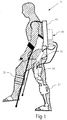
- the actuation system can be used to control a mobile robotic exoskeleton.
- Exoskeletons can be used for various applications, such as aiding able bodied persons to carry extra weight and enabling paraplegics who have lost use of their lower limbs to walk.
- an exoskeleton 10 has left and right legs 21 and 22, each leg having hydraulic cylinders 30 and 31 configured to respectively actuate the knee and hip of that leg.
- the four hydraulic cylinders are in communication with an actuation system 50 that forms part of a torso 60 of exoskeleton 10.
- Actuation system 50 is the primary object of this invention as actuation system 50 overcomes significant limitations of the known art.
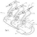
- actuation system 50 is shown that is capable of powering three degrees of freedom.
- a prime mover in this case an electric motor 101, rotates a drive shaft 102 based on signals from a controller 103.
- a controller 103 In practice, such an arrangement will require bearings, support structure, and an outer enclosure but, as these are not objects of the invention and are well understood in the art, they are not shown here.
- Three actuation modules, 110, 120, and 130, are shown coupled to drive shaft 102.
- Each actuation module is preferably equivalent. In the embodiment shown, there are three actuation modules, but in some embodiments there may be two, four, or more actuation modules. The only practical limit to the number of actuation modules is the size and strength of drive shaft 102. Below is set forth a discussion of actuation module 110, but the discussion could apply just as well to any actuation modules.
- Actuation module 110 contains the following components: displacement actuator 111, pump housing 112, pump core 113, hydraulic lines 114, output actuator 115 (which could constitute a wide range of actuators, including hydraulic cylinders 30 and 31), and feedback sensor 116.
- the pump can be any type of hydraulic pump that allows over center operation.
- Displacement actuator 111 varies the displacement of variable displacement pump by translating housing 112. In some embodiments, displacement actuator 111 could rotate pump housing 112 to vary the pump displacement. In the preferred embodiment, displacement actuator 111 is an electric actuator, such as a voice coil motor. Displacement actuator 111 does not contribute substantial power to the motion of output actuator 115, instead displacement actuator 111 controls the motion of output actuator 115 by varying the displacement of variable displacement pump 117. It should be understood, however, that the forces applied by the displacement actuator necessarily include components related to the pressure generated by the pump. These forces are generally small, but can contribute substantially to overall power loss in the system because displacement actuator 111 must overcome them. These forces can be reduced by careful design of the pump, including specialized modifications to the pump which will be discussed later.
- Hydraulic lines 114 communicate the hydraulic working fluid from the pump to output actuator 115.
- output actuator 115 is shown as a linear hydraulic actuator, but could also be a rotary hydraulic actuator.
- the motion of output actuator 115 is monitored by feedback sensor 116.
- Feedback sensor 116 could indicate the position, the velocity, or both position and velocity of output actuator 115.
- sensors well understood in the art, including without restriction, potentiometers, encoders, and LVDTs.
- a force feedback sensor 126 might be used to monitor the force produced by the actuator.
- an actuator might include feedback sensors capable of sensing both force and position. It should be understood that the feedback sensors 116 and 126 are in communication with controller 103, although the connection is not shown in Figure 1 .
- Controller 103 controls the motion of electric motor 101, and displacement actuators 111, 121, and 131.
- Controller 103 may be a digital controller, such as a microcontroller or digital signal processor, or even an analog controller. In typical operation, controller 103 will maintain a relatively constant speed of drive shaft 102.
- the prime mover may also have a speed sensor 104, to allow controller 103 to monitor and control the speed of electric motor 101 and dive shaft 102. Controller 103 further receives signals from feedback sensor 116, and force feedback sensor 126.
- controller 103 uses feedback control to move displacement actuator 111, thereby changing the displacement of the hydraulic pump and changing the flow to the corresponding output actuator 115. In the preferred embodiment, this is achieved with a PID controller, which is well understood in the art, but a more complex nonlinear control system could also be used.
- the reference value to which controller 103 controls output actuator 115 is provided from a higher level control system that is not the object of this invention. The higher level control system could reside on controller 103 or on another controller that is in communication with controller 103, or even come from a human operator.
- the maximum displacement of each pump and the respective sizes of each output actuator may not be the same, but may be configured to match the requirements of each axis under the control of the actuation system.
- the ability to optimize the size of each actuation module for each individual axis enables a higher overall system efficiency.
- the controller 103 controls to several levels of rotational speed.
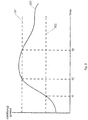
- Figure 3 depicts a plot of rotational speed 303 over time
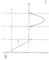
- Figure 4 depicts the control effort expended by the controller to control the rotational speed 303 of the prime mover over the same time.
- Two speed levels are shown, i.e., low set point 302, and high set point 301.
- the controller exerts control effort 305 to maintain the speed of the prime mover generally close to low set point 302.
- Low set point 302 is chosen to maintain the required flow to each output actuator given the maximum displacement of the variable displacement pump associated with each corresponding actuator.
- Low set point 302 need not, in general, be a constant value, and could change based on the flow requirements of the output actuators.
- the controller behavior is depicted as being approximately a proportional control, but it should be understood that this is merely exemplary and many types of feedback control would be appropriate.
- rotational speed 303 exceeds low set point 302, and the controller reduces control effort 305 to zero.
- control effort 305 remains zero. Because rotational speed 303 continues to increase during this time, the output actuators must be net absorbing power, although it is possible that any given output actuator could absorb power.
- rotational speed 303 has exceeded high set point 301.
- the actuation system has absorbed enough energy that the kinetic energy stored in its rotation has pushed rotational speed 303 to high set point 301.
- High set point 301 is chosen to be close to the maximum safe operating speed of the prime mover and drive shaft, a value dependent on the bearings chosen, the safe operating voltage of the controller, and other system design considerations.
- the controller applies negative control effort 305 to keep rotational speed 303 from climbing higher; during time t2 to t3, power is absorbed by the prime mover and returned to the electrical bus of the controller. This is often referred to as power regeneration as the prime mover acts as a generator, allowing the controller to return power to its corresponding power supply and extend system runtime because the power supply consists of batteries.
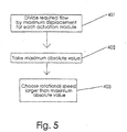
- the preferred speed of prime mover 101 is set according to three steps performed by controller 103, diagrammed in Figure 5 .
- controller 103 divides the flow required at each output actuator by the maximum displacement of the pump corresponding to that output actuator. If the maximum displacement of the pump is unequal on the two sides of the pump, the controller must take account of the sign of the flow as well. In general, the controller may estimate this flow requirement by measuring or estimating the speed of the output actuator. In some embodiments, the controller may further use the acceleration of the output actuator or other outside information to improve this estimate. In other embodiments, where actuation system 50 is part of a device, the device may signal controller 103 about future flow requirements.
- controller 103 computes the maximum of the flows for all actuation modules. In choosing step 403, controller 103 chooses a preferred speed that is slightly larger than this maximum value. How much larger the value must be depends on the application. When controller 103 operates at a higher sampling frequency, when prime mover 101 is generally overpowered with respect to the needs of the output actuators, and when the device using the actuation system does not produce rapid, dynamic motion, the preferred speed may be closer to the maximum value; when the reverse is true, the preferred speed may be required to be much larger. In some embodiments, it may be possible for controller 103 to change how much larger the preferred speed is than the maximum value based on how the device is operating.
- actuation system 50 is part of an overall device, such as exoskeleton 10, and the device can signal actuation system 50.
- this signal might be a digital command, in others an analog signal, and in yet others, a mechanical motion.
- Figure 6 depicts an embodiment of high level signal 504 over time.
- device signal 504 is at low level 501, indicating to controller 103 that the device is in a relatively non-dynamic situation, or in a situation where high efficiency is most important (e.g., when the device power source is low).
- controller 103 reduces the desired rotational speed of prime mover 101.
- device signal 504 changes to high level 502, indicating that the device needs dynamic performance at the expense of lower efficiency.
- controller 103 increases the rotational speed of prime mover 101, putting more kinetic energy into the rotational speed 303 of the drive train and prime mover, but resulting in greater frictional losses.
- device signal 504 changes to medium level 503, indicating that the device should operate at a normal level.
- controller 103 decreases the rotational speed of prime mover 101.
- device signal 504 need have three levels as in this example, but rather the resolution of device signal 504 will depend on the nature of the device using actuation system 50.
- the embodiments discussed have assumed a simple model of power loss, namely that the efficiency of actuation system 50 monotonically decreases with the speed of prime mover 101 and drive shaft 102, that can be further refined.
- the efficiency of the systems depends on the efficiency of the variable displacement hydraulic pumps, and while most variable displacement hydraulic pumps achieve maximum efficiency when they operate near their maximum displacement, the behavior is complex and highly dependent on the geometry of the pump.
- controller 103 given an accurate model of the pump efficiency, and the efficiency of the other components, can optimize the prime mover speed in order to maximize the efficiency of actuation system 50.
- Methods for optimizing the performance of a system with one unconstrained degree of freedom, in this case prime mover speed are well within the level of understanding in the art.
- controller 103 may choose the speed of prime mover 101 to maximize the life of the pump. In other embodiments, controller 103 may minimize acoustic volume so that the device is less audible, maximize actuation performance so that the device has maximum bandwidth, or minimize the temperature of the hydraulic working fluid so that the device can cool down. In each embodiment, it is only necessary to build a model of the response of the parameter of interest to prime mover speed and use optimization techniques well understood in the art. Often, these models will be very simple.
- the device may signal controller 103 which of these parameters should be optimized during operation.
- a human operator may be involved in deciding which parameter should be optimized.
- the device might possess an "eco" button that, when pressed, indicates to controller 103 that it should optimize for high efficiency at the expense of performance.
- controller 103 has more latitude to optimize performance.
- two degrees of freedom i.e., prime mover 101 and displacement actuator 111, together control the motion of output actuator 115.
- controller 103 can freely trade rotational speed of prime mover 101 and the displacement of variable displacement pump 117 without changing the performance of other actuation modules. This is particularly important in applications where there is one degree of freedom in a situation where regeneration is common.
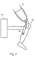
- Figure 7 One such example is shown in Figure 7 where actuation system 50 is included in transfemoral prosthetic 180 worn by person 181.
- actuation system 50 contains only one actuation module 110 with the corresponding output actuator 184 configured to control the flexion and extension of transfemoral prosthetic 180.
- the human knee will absorb mechanical power.
- most prosthetic devices cannot regenerate this absorbed power, even when the devices are powered, because the power level is too low to capture. Instead, prosthetic knees dissipate this power.
- Some embodiments, such as those illustrated in US patent 8,231,688 attempt to regenerate power with a fixed displacement pump, but cannot maximize their power regeneration and control the motion of the prosthetic at the same time because they can control only one input.
- controller 103 can control displacement actuator 111 to maximize the efficiency of power regeneration to prime mover 101. In general, this requires maximizing the displacement of variable displacement hydraulic pump 117 so that the rotational speed of prime mover 101 is maximized. In some embodiments, controller 103 may seek to target the displacement of variable displacement pump 117 near its maximum value, but low enough that controller 103 may make quick adjustments to the motion of output actuator 115 (or 184) by changing the displacement while making gross adjustments to the motion of output actuator 115 by changing the speed of prime mover 101.
- displacement actuator 111 there are many possible embodiments for displacement actuator 111 that are well known in the art, such as brushed, brushless, or stepper motors, or even electromagnets.
- a transmission e.g., gearbox, planetary gear, etc can be arranged between displacement actuator 111 and variable displacement pump 117 because the motor will not produce sufficient force.
- displacement actuator 111 and any accompanying transmission it is generally preferable for displacement actuator 111 and any accompanying transmission to be chosen such that the controlling motor may be moved by loads generated by variable displacement pump 117. This is often referred to as being "backdrivable.”
- Making displacement actuator 111 and transmission backdrivable allows forces that are working in the direction of desired motion to help with that motion. Furthermore, such designs necessarily have low friction, leading to a higher efficiency.
- Examples of preferred embodiments generally include a voice coil motor, brushless motor, toroidal motor, or any electrical actuator directly coupled to variable displacement pump 117, or coupled through a transmission that is backdrivable.
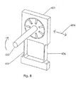
- pump housing 112 is mounted to the actuation system through a flexural element.
- flexural pump housing 601 includes first and second flexural bars 605 and 606 respectively, that allow for small motions along deflection axis 604 but generally resist motion in other axes.
- the flexural elements must withstand the strain caused by the eccentricity of the pump.
- displacement actuator 111 could be a piezoelectric device. In some embodiments, it may be beneficial to sense the deflection of the flexures with a strain gauge.
- variable displacement pump 117 may be used for variable displacement pump 117 in order to reduce loading on displacement actuator 111. Reducing loads on displacement actuator 111 directly improves the performance of actuation system 50 because power used by displacement actuator 111 is effectively lost.
- Load on the pump may occur because there is a slight asymmetry in the loading on most pumps. In some cases this loading may be static, it may vary in magnitude according to the relative pressures on the inlet and outlet of the pump, or it may vary as a function of the pump angular position due to pistons or vanes crossing the ports of the pump. In one embodiment, shown in Figure 9 , these loads may be partially canceled by building a pump 701 to have two pump cores 711 and 712 both within the same housing 702.
- the flow outputs from the two pump cores are combined so that the loads on the two pumps are equal but opposite. This may be achieved by counter-rotating the pump cores, or by porting the pump cores 180 degrees out of phase and keeping their direction of rotation identical.
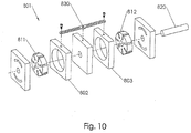
- a pump 801 contains two pump cores 811 and 812 both coupled to the same drive shaft 820.
- the outlets of the two pump cores are combined as in the previous embodiment.
- These housings have a mechanism 830 that moves them equal and opposite amounts when driven by the displacement actuator (not shown). While in the figure mechanism 830 is shown as a simple pinned lever, it should be understood that there are many simple mechanisms for generating such motion and mechanism 830 is intended only to illustrate but not restrict these possibilities.
- mechanism 830 the displacement of the two pump cores are changed in opposition, and asymmetric loads on the displacement actuator are neutralized.
- This embodiment has the advantage that only one drive shaft is required (where the embodiment of Figure 9 would require two drive shafts), but requires mechanism 830, which adds complexity to the pump.
- the losses associated with the pumps will increase, but this may be balanced by the designer against the losses associated with higher loads that must driven by the controlling motors if the pumps are not coupled.
Description
- The present invention relates to a high efficiency, low mass hydraulic actuation system for mobile robotics, and to mobile platforms in general, where the absence of AC mains requires particular attention to overall actuator system efficiency.
- Significant effort has been spent attempting to adapt stationary, industrial hydraulic actuation systems to mobile needs, but these systems generally have poor efficiency, being tenable only when used with a combustion engine. The state of the art solution today is to use low efficiency hydraulic servo valves. While these valves have exceptional control performance, they have very low efficiencies and are therefore ill suited to battery powered systems. Even in applications where efficiency is not a requirement, better efficiency can lead to significant energy savings and reduced heat loading. An exemplary hydraulic actuation system is described in
JP 2008/057687 - The state of the art in mobile robotic actuators is one of two varieties: (1) an electric motor coupled to each axis under control using a high ratio transmission such as a harmonic drive or ball screw; or (2) an electric motor driving a hydraulic pump in parallel with a hydraulic accumulator to create a constant pressure hydraulic supply rail and a hydraulic servo valve at each axis. Option (1) is the simpler solution but results in a high inertia at the axis because of the transmission, but this transmission is fundamental to the characteristics of electric motors and cannot be avoided until a conductor with a substantially lower resistance than copper can be used in electric motor design. Option (2) provides better performance, but at an efficiency (essentially because of the servo valves) that cannot be tolerated in a battery powered application. Although other actuators, such as electroactive polymers and pneumatic artificial muscles as well as other pneumatic or muscle like actuators, offer other solution paths, they have not yet reached a state where they can be used in intensive mobile applications. Major commercial endeavors and research platforms that are designed with commercial intent such as Honda's ASIMO, the Boston Dynamics BIG DOG, and iRobot's line of PACKBOTs, use either solution (1) or (2) above without exception.
- According to an aspect of the present invention, there is provided a system for hydraulically actuating at least one degree of freedom as claimed in
claim 1. According to an aspect of the present invention, there is provided a method for controlling a hydraulic actuation system as claimed in claim 8. - The present system is concerned with employing an hydraulic actuator with a theoretical efficiency higher than that of an electric drivetrain. The actuation system is based around a miniature variable displacement hydraulic pump. Variable displacement pumps are well known in the art of hydraulics. Like a fixed displacement pump they convert rotary shaft motion into hydraulic fluid motion but, unlike a fixed displacement pump, a variable displacement pump has a rotary shaft input and an additional input that controls the displacement of the pump. Variable displacement pumps have been used in hydraulic systems to provide purely mechanical system control, often to maintain a constant pressure supply by connecting the mechanism varying the pump displacement to a spring opposing the system pressure. Some variable displacement pump are over-center variable displacement pumps, that is, the displacement may be decreased to zero - at which point the pump generates no flow - and continue past zero so that the direction of the hydraulic fluid flow may be reversed purely by varying the pump displacement. There are many classes of hydraulic pumps that can be designed to be over-center variable displacement hydraulic pumps, including radial piston pumps, axial piston pumps, and vane pumps.
- The present invention uses a single variable displacement hydraulic pump to drive each axis under control. The power input shaft of each variable displacement pump is connected to a common rotary drive shaft, and each variable displacement pump has an individual electric motor controlling the displacement of that variable displacement pump. The common drive shaft is connected to one driving electric motor that acts as a prime mover. In a typical configuration of N axes, there would be one driving electric motor, and N actuation modules. Each actuation module would have one pump, one controlling motor, and one output actuator. The driving motor provides all the mechanical power for the system. Each controlling motor must provide only the power needed to overcome friction and the inertia of the part of the pump that must be moved in order to vary the displacement. Generally, either the system pressure does not work against the pump displacement mechanism, or the component of system pressure that does work against the pump displacement mechanism is very small, and therefore the controlling motors do not need to overcome the system pressure. The loads that must be overcome by the controlling motor in order to change the pump displacement may be quite small if the system is designed appropriately. With an optimized pump design, this actuation system can achieve the control bandwidth of a similar sized hydraulic servo valve system. The system can, of course, be run as a one-axis system, and this arrangement may be beneficial in specific applications, but many of its unique advantages scale favorably as the number of axes increases.
- The invention has a number of advantages. Like a hydraulic system using servo valves, the weight at the axis is only the actuator, such as a hydraulic cylinder or hydraulic motor. However, the system is not controlled as by dissipating power in a valve but rather by varying the displacement of the pump to get the desired actuator output. By positioning the pump near zero displacement, the output actuator can be effectively used as a bidirectional controlled damper to slow or hold position regardless of the load on the axis. Furthermore, all loads applied to the actuators are reflected back through the variable displacement pumps onto a single drive shaft driven by a single motor. The common drive arrangement has four principle advantages:
- 1. 1. All energy used to move the output actuators is produced by a single prime mover. This is essential if the prime mover is a combustion engine. When the prime mover is an electric motor, a single electric motor will produce power more efficiently than several small electric motors.
- 2. The inertia of the prime mover and drive shaft help absorb peak loads. In a direct drive electrical system; additional inertia reduces actuation bandwidth, requiring smaller, less efficient motors.
- 3. Energy generated by an output actuator is transferred mechanically to the drive shaft and then directly to other output actuators without being converted to electrical energy. Thus regeneration is possible even when the prime mover cannot regenerate power, as in the case of an engine. If the net total of all output actuators produce more power than they absorb, and the prime mover can regenerate power, then electric power may be returned to the power supply.
- 4. The speed of the prime mover can vary while the controller continues to control the motion of the output actuators, provided the speed of the prime mover is sufficient to produce the required flow to each output actuator given the maximum displacement of the variable displacement pump associated with that actuator. Thus the speed of the prime mover is a free variable available for optimization by a high level process and the rate may be varied in order to maximize efficiency, minimize noise, provide a period of higher flow rates to allow for fast maneuvers, and/or save power during a period of inactivity.
- There are a number of features of the invention that improve it's capabilities and efficiency, and these apply generally, regardless of the type of pump used in the invention. Additional object features and advantages of the invention will become more readily apparent from the following detailed description of preferred embodiments when taken in conjunction with the following drawings wherein like reference numerals refer to corresponding parts in several views.
-
-
Figure 1 is a view of an exoskeleton including an hydraulic actuator system according to the invention; -
Figure 2 is a view of the overall system including three actuation modules; -
Figure 3 is a plot of rotational speed over time that demonstrates how multiple rotation speeds for the prime mover may be used; -
Figure 4 is a plot of control effort applied by the controller to regulate the rotational speed shown inFigure 3 ; -
Figure 5 is a flow chart that illustrates a simple heuristic for improving the performance of the system; -
Figure 6 is a plot of an external signal indicating to the actuation system in which of several modes it should operate; -
Figure 7 is a schematic view of a prosthetic knee arrangement employing the actuator system of the invention; -
Figure 8 is a view of a pump with a flexurally mounted housing, an arrangement with certain advantages for the invention; -
Figure 9 is a view of a load balanced pump having one common housing; and -
Figure 10 is a view of a load balanced pump having two linked housings. - Described in detail below is a new approach to high efficiency hydraulic actuation that has broad application. In the description, for purposes of explanation, numerous specific details are set forth in order to provide a thorough understanding of the present invention. It will be obvious, however, to one skilled in the art that the present invention may be practiced without these specific details.
- In the preferred embodiment, the actuation system can be used to control a mobile robotic exoskeleton. Exoskeletons can be used for various applications, such as aiding able bodied persons to carry extra weight and enabling paraplegics who have lost use of their lower limbs to walk. With reference to
Figure 1 , anexoskeleton 10 has left andright legs hydraulic cylinders actuation system 50 that forms part of atorso 60 ofexoskeleton 10.Actuation system 50 is the primary object of this invention asactuation system 50 overcomes significant limitations of the known art. - With reference to
Figure 2 , in one exemplary embodiment,actuation system 50 is shown that is capable of powering three degrees of freedom. A prime mover, in this case anelectric motor 101, rotates a drive shaft 102 based on signals from acontroller 103. In practice, such an arrangement will require bearings, support structure, and an outer enclosure but, as these are not objects of the invention and are well understood in the art, they are not shown here. Three actuation modules, 110, 120, and 130, are shown coupled to drive shaft 102. - Each actuation module is preferably equivalent. In the embodiment shown, there are three actuation modules, but in some embodiments there may be two, four, or more actuation modules. The only practical limit to the number of actuation modules is the size and strength of drive shaft 102. Below is set forth a discussion of
actuation module 110, but the discussion could apply just as well to any actuation modules.Actuation module 110 contains the following components:displacement actuator 111, pumphousing 112,pump core 113,hydraulic lines 114, output actuator 115 (which could constitute a wide range of actuators, includinghydraulic cylinders 30 and 31), and feedback sensor 116. The pump can be any type of hydraulic pump that allows over center operation. That is, operation where the displacement may be positive or negative so that the direction of flow from the pump may be reversed without changing the direction of input rotation but by instead changing the displacement. There are many types of pumps that can be designed to have over center capability, including vane and radial piston pumps. In general, any variable displacement pump with over center capability is effective and use of a specific design is not intended to limit the scope of the discussion. -
Displacement actuator 111 varies the displacement of variable displacement pump by translatinghousing 112. In some embodiments,displacement actuator 111 could rotate pumphousing 112 to vary the pump displacement. In the preferred embodiment,displacement actuator 111 is an electric actuator, such as a voice coil motor.Displacement actuator 111 does not contribute substantial power to the motion ofoutput actuator 115, instead displacement actuator 111 controls the motion ofoutput actuator 115 by varying the displacement of variable displacement pump 117. It should be understood, however, that the forces applied by the displacement actuator necessarily include components related to the pressure generated by the pump. These forces are generally small, but can contribute substantially to overall power loss in the system becausedisplacement actuator 111 must overcome them. These forces can be reduced by careful design of the pump, including specialized modifications to the pump which will be discussed later. - It is understood that a variable displacement pump is more complex than shown here, requiring outer housings, bearing arrangements, and porting, with these items not being shown here for clarity.
Hydraulic lines 114 communicate the hydraulic working fluid from the pump tooutput actuator 115. Hereoutput actuator 115 is shown as a linear hydraulic actuator, but could also be a rotary hydraulic actuator. The motion ofoutput actuator 115 is monitored by feedback sensor 116. Feedback sensor 116 could indicate the position, the velocity, or both position and velocity ofoutput actuator 115. There are many such sensors well understood in the art, including without restriction, potentiometers, encoders, and LVDTs. In some embodiments aforce feedback sensor 126 might be used to monitor the force produced by the actuator. There are many such force sensors well understood in the art, including strain gauges, pressure sensors, and sensors utilizing piezoresistive materials. In some embodiments, not depicted here, an actuator might include feedback sensors capable of sensing both force and position. It should be understood that thefeedback sensors 116 and 126 are in communication withcontroller 103, although the connection is not shown inFigure 1 . -
Controller 103 controls the motion ofelectric motor 101, anddisplacement actuators Controller 103 may be a digital controller, such as a microcontroller or digital signal processor, or even an analog controller. In typical operation,controller 103 will maintain a relatively constant speed of drive shaft 102. In some embodiments, the prime mover may also have aspeed sensor 104, to allowcontroller 103 to monitor and control the speed ofelectric motor 101 and dive shaft 102.Controller 103 further receives signals from feedback sensor 116, andforce feedback sensor 126. - Again referring to
actuation module 110, but equally applicable to each actuation module,controller 103 uses feedback control to movedisplacement actuator 111, thereby changing the displacement of the hydraulic pump and changing the flow to thecorresponding output actuator 115. In the preferred embodiment, this is achieved with a PID controller, which is well understood in the art, but a more complex nonlinear control system could also be used. In general, the reference value to whichcontroller 103controls output actuator 115 is provided from a higher level control system that is not the object of this invention. The higher level control system could reside oncontroller 103 or on another controller that is in communication withcontroller 103, or even come from a human operator. - In some embodiments, the maximum displacement of each pump and the respective sizes of each output actuator may not be the same, but may be configured to match the requirements of each axis under the control of the actuation system. The ability to optimize the size of each actuation module for each individual axis enables a higher overall system efficiency.
- There are several embodiments for controlling the speed of the prime mover. In the first exemplary embodiment the
controller 103 controls to several levels of rotational speed.Figure 3 depicts a plot ofrotational speed 303 over time, andFigure 4 depicts the control effort expended by the controller to control therotational speed 303 of the prime mover over the same time. Two speed levels are shown, i.e.,low set point 302, andhigh set point 301. Before time t1, the controller exertscontrol effort 305 to maintain the speed of the prime mover generally close tolow set point 302.Low set point 302 is chosen to maintain the required flow to each output actuator given the maximum displacement of the variable displacement pump associated with each corresponding actuator.Low set point 302 need not, in general, be a constant value, and could change based on the flow requirements of the output actuators. The controller behavior is depicted as being approximately a proportional control, but it should be understood that this is merely exemplary and many types of feedback control would be appropriate. At time t1,rotational speed 303 exceedslow set point 302, and the controller reducescontrol effort 305 to zero. Between times t1 and t2,control effort 305 remains zero. Becauserotational speed 303 continues to increase during this time, the output actuators must be net absorbing power, although it is possible that any given output actuator could absorb power. At time t2,rotational speed 303 has exceededhigh set point 301. That is, the actuation system has absorbed enough energy that the kinetic energy stored in its rotation has pushedrotational speed 303 tohigh set point 301.High set point 301 is chosen to be close to the maximum safe operating speed of the prime mover and drive shaft, a value dependent on the bearings chosen, the safe operating voltage of the controller, and other system design considerations. The controller appliesnegative control effort 305 to keeprotational speed 303 from climbing higher; during time t2 to t3, power is absorbed by the prime mover and returned to the electrical bus of the controller. This is often referred to as power regeneration as the prime mover acts as a generator, allowing the controller to return power to its corresponding power supply and extend system runtime because the power supply consists of batteries. However, more unique during this example of operation of the actuation system is that, during time t1 to t2, no power is required to drive the prime mover and power is transferred mechanically from one output actuator to another. This is as opposed to a conventional regeneration arrangement where transferring power from one axis to another requires converting energy from mechanical to electrical and then back to electrical, with the inefficiencies at each step in this process limiting its efficiency and therefore limiting its utility. Finally, at time t3,rotational speed 303 drops belowhigh set point 301, andcontrol effort 305 is reduced to zero. - It is important to note that the property elucidated in
Figure 4 , that the rotational speed of the prime mover and associated drive shaft serves to store kinetic energy in a way that facilitates mechanical regeneration of power from one axis to another, has implications for the design of the actuation system as a whole. In general, it is desired for the prime mover and drive shaft to have as large a rotational inertia as feasible because this will serve to store more kinetic energy. As a result, the tendency in the design will be to makeprime mover 101 as large as feasible, which will make the prime mover more efficient as larger motors are generally more efficient than smaller motors for a given non-reversing load. This is in contrast to a conventional electromechanical actuator where the inertia of the electric motor driving the actuator must be accelerated and decelerated and where the inertia therefore serves to reduce the actuator bandwidth. In these conventional actuators, the designer is driven to choose as small a motor as possible, to minimize inertia, which therefore also reduces actuation efficiency. - In another embodiment, which may be combined with the previous embodiment, the preferred speed of
prime mover 101 is set according to three steps performed bycontroller 103, diagrammed inFigure 5 . Inflow step 401,controller 103 divides the flow required at each output actuator by the maximum displacement of the pump corresponding to that output actuator. If the maximum displacement of the pump is unequal on the two sides of the pump, the controller must take account of the sign of the flow as well. In general, the controller may estimate this flow requirement by measuring or estimating the speed of the output actuator. In some embodiments, the controller may further use the acceleration of the output actuator or other outside information to improve this estimate. In other embodiments, whereactuation system 50 is part of a device, the device may signalcontroller 103 about future flow requirements. In maximizingstep 402,controller 103 computes the maximum of the flows for all actuation modules. In choosingstep 403,controller 103 chooses a preferred speed that is slightly larger than this maximum value. How much larger the value must be depends on the application. Whencontroller 103 operates at a higher sampling frequency, whenprime mover 101 is generally overpowered with respect to the needs of the output actuators, and when the device using the actuation system does not produce rapid, dynamic motion, the preferred speed may be closer to the maximum value; when the reverse is true, the preferred speed may be required to be much larger. In some embodiments, it may be possible forcontroller 103 to change how much larger the preferred speed is than the maximum value based on how the device is operating. - In yet a further embodiment,
actuation system 50 is part of an overall device, such asexoskeleton 10, and the device can signalactuation system 50. In some embodiments this signal might be a digital command, in others an analog signal, and in yet others, a mechanical motion.Figure 6 depicts an embodiment ofhigh level signal 504 over time. Before time t4,device signal 504 is atlow level 501, indicating tocontroller 103 that the device is in a relatively non-dynamic situation, or in a situation where high efficiency is most important (e.g., when the device power source is low). As a result,controller 103 reduces the desired rotational speed ofprime mover 101. At time t4, device signal 504 changes tohigh level 502, indicating that the device needs dynamic performance at the expense of lower efficiency. As a result,controller 103 increases the rotational speed ofprime mover 101, putting more kinetic energy into therotational speed 303 of the drive train and prime mover, but resulting in greater frictional losses. At time t3, device signal 504 changes tomedium level 503, indicating that the device should operate at a normal level. As a result,controller 103 decreases the rotational speed ofprime mover 101. At this point, it should be noted that there is no reason thatdevice signal 504 need have three levels as in this example, but rather the resolution ofdevice signal 504 will depend on the nature of the device usingactuation system 50. - The embodiments discussed have assumed a simple model of power loss, namely that the efficiency of
actuation system 50 monotonically decreases with the speed ofprime mover 101 and drive shaft 102, that can be further refined. The efficiency of the systems depends on the efficiency of the variable displacement hydraulic pumps, and while most variable displacement hydraulic pumps achieve maximum efficiency when they operate near their maximum displacement, the behavior is complex and highly dependent on the geometry of the pump. However,controller 103, given an accurate model of the pump efficiency, and the efficiency of the other components, can optimize the prime mover speed in order to maximize the efficiency ofactuation system 50. Methods for optimizing the performance of a system with one unconstrained degree of freedom, in this case prime mover speed, are well within the level of understanding in the art. - In another embodiment, efficiency may not be the most important metric for optimization of
actuation system 50. In some embodiments,controller 103 may choose the speed ofprime mover 101 to maximize the life of the pump. In other embodiments,controller 103 may minimize acoustic volume so that the device is less audible, maximize actuation performance so that the device has maximum bandwidth, or minimize the temperature of the hydraulic working fluid so that the device can cool down. In each embodiment, it is only necessary to build a model of the response of the parameter of interest to prime mover speed and use optimization techniques well understood in the art. Often, these models will be very simple. For instance, in the case of minimizing the acoustic noise of the system, it is merely necessary to characterize the noise produced by the system as a function of prime mover speed at various output actuator speeds and load. This could be done theoretically or experimentally. Then the controller could be instructed to avoid combinations of prime mover speeds, actuator speeds and loads that produce the most undesired noise. Finally, the device may signalcontroller 103 which of these parameters should be optimized during operation. In some embodiments, a human operator may be involved in deciding which parameter should be optimized. For example, the device might possess an "eco" button that, when pressed, indicates tocontroller 103 that it should optimize for high efficiency at the expense of performance. - In yet a further embodiment where
actuation system 50 has only oneactuation module 110,controller 103 has more latitude to optimize performance. In this special case, two degrees of freedom, i.e.,prime mover 101 anddisplacement actuator 111, together control the motion ofoutput actuator 115. Here,controller 103 can freely trade rotational speed ofprime mover 101 and the displacement of variable displacement pump 117 without changing the performance of other actuation modules. This is particularly important in applications where there is one degree of freedom in a situation where regeneration is common. One such example is shown inFigure 7 whereactuation system 50 is included in transfemoral prosthetic 180 worn byperson 181. Although the internal components ofactuation system 50 are not shown inFigure 7 , it should be understood thatactuation system 50 contains only oneactuation module 110 with thecorresponding output actuator 184 configured to control the flexion and extension oftransfemoral prosthetic 180. During walking, the human knee will absorb mechanical power. However, most prosthetic devices cannot regenerate this absorbed power, even when the devices are powered, because the power level is too low to capture. Instead, prosthetic knees dissipate this power. Some embodiments, such as those illustrated inUS patent 8,231,688 attempt to regenerate power with a fixed displacement pump, but cannot maximize their power regeneration and control the motion of the prosthetic at the same time because they can control only one input. However, by implementing an embodiment ofactuation system 50 with only oneactuation module 110,controller 103 can controldisplacement actuator 111 to maximize the efficiency of power regeneration toprime mover 101. In general, this requires maximizing the displacement of variable displacement hydraulic pump 117 so that the rotational speed ofprime mover 101 is maximized. In some embodiments,controller 103 may seek to target the displacement of variable displacement pump 117 near its maximum value, but low enough thatcontroller 103 may make quick adjustments to the motion of output actuator 115 (or 184) by changing the displacement while making gross adjustments to the motion ofoutput actuator 115 by changing the speed ofprime mover 101. There are many other optimization schemes that can be used here but, in general, the idea is to match the impedance ofprime mover 101 to the load by varying the displacement of variable displacement pump 117. It is important to understand that this has broad application to any situation where energy is absorbed from the device in whichactuation system 50 is implemented, and the rate at which that energy is absorbed is irregular. A partial list of applications, without limitation, includes powered vehicle suspensions, machines generating power from waves, and machines generating power from wind. - There are many possible embodiments for
displacement actuator 111 that are well known in the art, such as brushed, brushless, or stepper motors, or even electromagnets. For some configurations a transmission, e.g., gearbox, planetary gear, etc can be arranged betweendisplacement actuator 111 and variable displacement pump 117 because the motor will not produce sufficient force. It is generally preferable fordisplacement actuator 111 and any accompanying transmission to be chosen such that the controlling motor may be moved by loads generated by variable displacement pump 117. This is often referred to as being "backdrivable." Makingdisplacement actuator 111 and transmission backdrivable allows forces that are working in the direction of desired motion to help with that motion. Furthermore, such designs necessarily have low friction, leading to a higher efficiency. Because none of the power used by the displacement actuators contributes to work done by the output actuators, higher efficiency of the controlling motor will directly translate into higher system efficiency. Similarly, a more efficient displacement actuator will, for the same power, yield a higher bandwidth. Examples of preferred embodiments generally include a voice coil motor, brushless motor, toroidal motor, or any electrical actuator directly coupled to variable displacement pump 117, or coupled through a transmission that is backdrivable. - In another embodiment, pump
housing 112, is mounted to the actuation system through a flexural element.Figure 8 shows such an arrangement. Here,flexural pump housing 601 includes first and secondflexural bars deflection axis 604 but generally resist motion in other axes. The flexural elements must withstand the strain caused by the eccentricity of the pump. In some of these flexural embodiments,displacement actuator 111 could be a piezoelectric device. In some embodiments, it may be beneficial to sense the deflection of the flexures with a strain gauge. - In many of these embodiments it may be advantageous to submerge
pump core 112 and pumphousing 113 in the oil within an outer housing so that heat conduction is maximized and friction is minimized. In this embodiment, it is important that this oil is ported to the system reservoir so that motion ofpump core 112 and pumphousing 113 is not impeded. - In some embodiments, unconventional designs may be used for variable displacement pump 117 in order to reduce loading on
displacement actuator 111. Reducing loads ondisplacement actuator 111 directly improves the performance ofactuation system 50 because power used bydisplacement actuator 111 is effectively lost. - In general, minimizing the mass of the pump that must be moved when displacement is changed, as well as minimizing the friction associated with changing displacement, will result in less power required by the controlling motor. But there are other loads reflected onto the controlling motors, and those will be discussed here.
- As discussed above, it is possible, in some cases, that forces acting in the direction of motion of the controlling motors can be helpful; however, reducing the total load will improve the system efficiency. Load on the pump may occur because there is a slight asymmetry in the loading on most pumps. In some cases this loading may be static, it may vary in magnitude according to the relative pressures on the inlet and outlet of the pump, or it may vary as a function of the pump angular position due to pistons or vanes crossing the ports of the pump. In one embodiment, shown in
Figure 9 , these loads may be partially canceled by building apump 701 to have twopump cores same housing 702. In this embodiment, the flow outputs from the two pump cores are combined so that the loads on the two pumps are equal but opposite. This may be achieved by counter-rotating the pump cores, or by porting thepump cores 180 degrees out of phase and keeping their direction of rotation identical. - In another similar embodiment shown in
Figure 10 , apump 801 contains twopump cores same drive shaft 820. Here the outlets of the two pump cores are combined as in the previous embodiment. However, unlike the previous embodiment, there are two housings, 802 and 803 respectively forpump cores mechanism 830 that moves them equal and opposite amounts when driven by the displacement actuator (not shown). While in thefigure mechanism 830 is shown as a simple pinned lever, it should be understood that there are many simple mechanisms for generating such motion andmechanism 830 is intended only to illustrate but not restrict these possibilities. As a result ofmechanism 830, the displacement of the two pump cores are changed in opposition, and asymmetric loads on the displacement actuator are neutralized. This embodiment has the advantage that only one drive shaft is required (where the embodiment ofFigure 9 would require two drive shafts), but requiresmechanism 830, which adds complexity to the pump. - In either of these two embodiments, the losses associated with the pumps will increase, but this may be balanced by the designer against the losses associated with higher loads that must driven by the controlling motors if the pumps are not coupled. In some embodiments, it may be desirable to introduce a slight phase between each of the pumps connected to the driving shaft so that the peak torque required by each pump arrives out of phase with the others. This feature could reduce the peak load experienced by the drive shaft and allow the controller to more effectively control the speed of the drive shaft.
- Although described with reference to preferred embodiments of the invention, it should be readily apparent that various changes and/or modifications could be made to the invention without departing from the scope of the invention as defined by the appended claims.
Claims (14)
- A system for hydraulically actuating at least one degree of freedom, said system comprising:at least two actuator modules (110,0120, 130),a single prime mover (101) for the at least two actuation modules (110,120,130), wherein the prime mover (101) produces rotary motion and is constituted by a battery powered electric motor, and each actuation module including:(1) an over-center variable displacement pump (117), said pump having:(a) a power input connection configured to power the pump (117) from said prime mover (101); and(b) a displacement varying input for varying the displacement of the pump (117); and(2) a displacement varying actuator (111,121,131) configured to modulate the displacement varying input of the pump (117);(3) an output actuator (115) in direct communication with the pump (117), said output actuator (115) being configured to drive a corresponding degree of freedom; and(4) a feedback measurement that represents a force or motion of the output actuator (115), said feedback measurement being constructed from at least one sensor (116); wherein the system also comprisesa controller (103) configured to control the prime mover (101) and the displacement varying actuator (111,121,131) for each of said at least two actuation modules (110,120,130), wherein said controller (103) further controls motion of the prime mover (101) and uses the feedback measurement to regulate, for a respective one of said at least two actuation modules (110,120,130), the force or motion of the output actuator (115) by controlling the displacement varying actuator (111,121,131).
- The system of claim 1, wherein said controller is configured to control a speed of the rotary motion to maximize power transferred from said variable displacement pump wherein controlling the force or motion of the output actuator results in power being transferred from said variable displacement pump.
- The system of claim 1 or 2, wherein the controller is configured to control an angular speed of the prime mover to be generally constant.
- The system of claim 1, 2 or 3, wherein the output actuator has a limited travel.
- The system of any preceding claim, wherein the controller is configured to control the prime mover to a rotational speed and the controller is configured to establish the rotational speed to maximize performance in regulating the force or motion of the output actuator.
- The system of any one of claims 1 to 4, wherein the controller is configured to control the prime mover to a rotational speed, the system is configured to be incorporated into a device, and said device signals said controller which of several modes of optimization the controller should use in order to choose the rational speed of the prime mover, said modes including at least two of the following: minimizing power loss, maximizing efficiency, maximizing pump life, minimizing acoustic volume, maximizing actuation performance, and minimizing system temperatures.
- The system of claim 6, wherein the device is configured to be operated by a human operator and the human operator provides input on which of said modes of optimization should be chosen.
- A method for controlling a hydraulic actuation system having at least one degree of freedom, a single prime mover (101) for at least two actuation modules (110,120,130), wherein the prime mover (101) produces rotary motion and is constituted by a battery powered electric motor, and a controller (103) for controlling motion of the prime mover (101), with each actuation module (110,120,130) including: an over-center variable displacement pump (117) having a power input connection configured to power the pump (117) from said prime mover (101) and a displacement varying input for varying the displacement of the pump (117); a displacement varying actuator (111,121,131) configured to modulate the displacement varying input of the pump (117); an output actuator (115) in direct communication with the pump (117), said output actuator (115) configured to drive a corresponding degree of freedom; and at least one sensor (116) establishing a feedback measurement that represents a force or motion of the output actuator (115), said method comprising:reading a value of each feedback measurement; andcontrolling the force or motion of the output actuator (115) by controlling the prime mover (101) and the displacement actuator (111,112,113) for the output actuator (115) of a respective one of said at least two actuation modules (110,120,130).
- The method of claim 8, wherein the controller controls the prime mover in three modes:(1) producing power when an angular speed of the prime mover is generally below a low set point,(2) producing no power when the angular speed of the prime mover is generally above said low set point but below a high set point, and(3) absorbing power when the angular speed of the prime mover is generally above said high set point.
- The method of claim 8 or 9, wherein the controller controls the prime mover to a rotational speed, with said rotational speed being chosen by the following steps:(1) the controller divides the flow required by each said output actuator by a maximum displacement of its corresponding variable displacement pump producing a required prime mover speed for that actuation module,(2) the controller computes a maximum speed that is the maximum of an absolute value of each of the said required prime mover speeds, and(3) the controller establishes said rotational speed to be slightly larger than said maximum speed.
- The method of claim 8 or 9, wherein the system is incorporated into a device, the controller controls a rotational speed of the prime mover and receives an external signal from the device, and, based on the external signal, the controller changes the rotational speed of the prime mover between at least two different values wherein lower values correspond to the device being in a rest state and higher values correspond to the device being in an active state.
- The method of claim 8 or 9, wherein the controller controls the prime mover to a rotational speed, the controller includes a model of power loss in the actuation system, and said controller establishes the rotational speed to minimize power loss.
- The method of claim 8 or 9, wherein the controller controls the prime mover to a rotational speed and said controller establishes the rotational speed to minimize acoustic volume.
- The method of claim 8 or 9, wherein the hydraulic actuation system is incorporated in a device, with the device estimating future flow requirements and signaling these future flow requirements to the controller, said controller utilizing the future flow requirements in place of a flow presently required by the output actuator.
Applications Claiming Priority (2)
| Application Number | Priority Date | Filing Date | Title |
|---|---|---|---|
| US201261693463P | 2012-08-27 | 2012-08-27 | |
| PCT/US2013/056832 WO2014035984A2 (en) | 2012-08-27 | 2013-08-27 | Hydraulic actuator system |
Publications (3)
| Publication Number | Publication Date |
|---|---|
| EP2888083A2 EP2888083A2 (en) | 2015-07-01 |
| EP2888083A4 EP2888083A4 (en) | 2016-06-01 |
| EP2888083B1 true EP2888083B1 (en) | 2020-05-06 |
Family
ID=50184604
Family Applications (1)
| Application Number | Title | Priority Date | Filing Date |
|---|---|---|---|
| EP13833152.5A Active EP2888083B1 (en) | 2012-08-27 | 2013-08-27 | Hydraulic actuator system |
Country Status (7)
| Country | Link |
|---|---|
| US (1) | US10352334B2 (en) |
| EP (1) | EP2888083B1 (en) |
| CN (1) | CN104582910B (en) |
| AU (1) | AU2013309005A1 (en) |
| CA (1) | CA2883185A1 (en) |
| IL (1) | IL237463A0 (en) |
| WO (1) | WO2014035984A2 (en) |
Families Citing this family (12)
| Publication number | Priority date | Publication date | Assignee | Title |
|---|---|---|---|---|
| US10561564B2 (en) | 2014-11-07 | 2020-02-18 | Unlimited Tomorrow, Inc. | Low profile exoskeleton |
| CN105114397A (en) * | 2015-09-06 | 2015-12-02 | 哈尔滨工业大学 | Fluid artificial muscle driving and controlling system |
| KR102395796B1 (en) * | 2015-11-06 | 2022-05-10 | 삼성전자주식회사 | A power transmitting module and a motion assist apparatus comprising thereof |
| CN106545535B (en) * | 2016-11-30 | 2018-08-03 | 深圳航天科技创新研究院 | A kind of robot motor drives hydraulic power system and control method |
| JP6958374B2 (en) * | 2018-01-18 | 2021-11-02 | トヨタ自動車株式会社 | Walking training device and its control method |
| DE102018106846B3 (en) * | 2018-03-22 | 2019-07-04 | HAWE Altenstadt Holding GmbH | Human exoskeleton |
| DE102018108638B3 (en) * | 2018-04-11 | 2019-05-16 | Hoerbiger Automatisierungstechnik Holding Gmbh | hydraulic system |
| DE102019205297A1 (en) * | 2019-04-12 | 2020-10-15 | Robert Bosch Gmbh | Hydrostatic working device and method for its control |
| US10830562B2 (en) * | 2019-04-14 | 2020-11-10 | Hamilton Sundstrand Corporation | Wearable power modules with distributed energy storage systems |
| WO2020211937A1 (en) * | 2019-04-17 | 2020-10-22 | Siemens Aktiengesellschaft | Stroke transmitter for an actuator device |
| FR3123204B1 (en) * | 2021-05-27 | 2023-11-17 | Robin Temporelli | Orthopedic device comprising at least one actuator |
| DE102021209477B4 (en) * | 2021-08-30 | 2023-04-20 | Robert Bosch Gesellschaft mit beschränkter Haftung | Electrohydraulic unit for supplying pressure medium and method for controlling an electrohydraulic unit |
Family Cites Families (17)
| Publication number | Priority date | Publication date | Assignee | Title |
|---|---|---|---|---|
| US5282460A (en) * | 1992-01-06 | 1994-02-01 | Joyce Ann Boldt | Three axis mechanical joint for a power assist device |
| US6205780B1 (en) * | 1996-01-10 | 2001-03-27 | Aeroquip-Vickers International Gmbh | Low-loss drive system for a plurality of hydraulic actuators |
| US6502393B1 (en) * | 2000-09-08 | 2003-01-07 | Husco International, Inc. | Hydraulic system with cross function regeneration |
| JP3674778B2 (en) * | 2001-09-27 | 2005-07-20 | 本田技研工業株式会社 | Leg joint assist device for legged mobile robot |
| JP2004011168A (en) * | 2002-06-04 | 2004-01-15 | Komatsu Ltd | Construction machinery |
| JP2005076781A (en) * | 2003-09-01 | 2005-03-24 | Shin Caterpillar Mitsubishi Ltd | Drive unit of working machine |
| US20050076781A1 (en) * | 2003-10-14 | 2005-04-14 | Hess Spencer W. | Desiccant dehumidifier with integrated hepa filter |
| JP4008465B2 (en) * | 2005-09-02 | 2007-11-14 | 本田技研工業株式会社 | Motion induction device |
| AU2007223733B2 (en) | 2006-03-09 | 2013-01-10 | The Regents Of The University Of California | Power generating leg |
| JP4999404B2 (en) * | 2006-08-31 | 2012-08-15 | カヤバ工業株式会社 | Hydraulic control device |
| US7798282B2 (en) * | 2008-03-04 | 2010-09-21 | Ford Global Technologies, Llc | Power assisted steering system |
| WO2009143161A1 (en) * | 2008-05-20 | 2009-11-26 | Berkeley Bionics | Device and method for decreasing energy consumption of a person by use of a lower extremity exoskeleton |
| EP2331026B1 (en) | 2008-06-16 | 2018-11-07 | The Regents of The University of California | Semi-actuated transfemoral prosthetic knee |
| US8096965B2 (en) * | 2008-10-13 | 2012-01-17 | Argo Medical Technologies Ltd. | Locomotion assisting device and method |
| CN101846109B (en) * | 2010-04-30 | 2012-08-29 | 太原理工大学 | Two-way flow rate continuous control valve |
| US20130125537A1 (en) * | 2010-07-30 | 2013-05-23 | Volvo Construction Equipment Ab | Swirl flow control system for construction equipment and method of controlling the same |
| DE102010040755A1 (en) * | 2010-09-14 | 2012-03-15 | Zf Friedrichshafen Ag | drive arrangement |
-
2013
- 2013-08-27 EP EP13833152.5A patent/EP2888083B1/en active Active
- 2013-08-27 CA CA2883185A patent/CA2883185A1/en not_active Abandoned
- 2013-08-27 CN CN201380044651.4A patent/CN104582910B/en active Active
- 2013-08-27 US US14/423,302 patent/US10352334B2/en active Active
- 2013-08-27 AU AU2013309005A patent/AU2013309005A1/en not_active Abandoned
- 2013-08-27 WO PCT/US2013/056832 patent/WO2014035984A2/en active Application Filing
-
2015
- 2015-02-26 IL IL237463A patent/IL237463A0/en unknown
Non-Patent Citations (1)
| Title |
|---|
| None * |
Also Published As
| Publication number | Publication date |
|---|---|
| AU2013309005A1 (en) | 2015-02-26 |
| WO2014035984A2 (en) | 2014-03-06 |
| CN104582910A (en) | 2015-04-29 |
| US10352334B2 (en) | 2019-07-16 |
| IL237463A0 (en) | 2015-04-30 |
| CN104582910B (en) | 2016-11-16 |
| US20150226234A1 (en) | 2015-08-13 |
| CA2883185A1 (en) | 2014-03-06 |
| WO2014035984A3 (en) | 2014-09-18 |
| EP2888083A2 (en) | 2015-07-01 |
| EP2888083A4 (en) | 2016-06-01 |
Similar Documents
| Publication | Publication Date | Title |
|---|---|---|
| EP2888083B1 (en) | Hydraulic actuator system | |
| JP7288926B2 (en) | Screw actuators for legged robots | |
| JP7303840B2 (en) | Transmission with integrated overload protection for legged robots | |
| Alfayad et al. | High performance integrated electro-hydraulic actuator for robotics–Part I: Principle, prototype design and first experiments | |
| Trimmer | Soft robots | |
| US8731716B2 (en) | Control logic for biomimetic joint actuators | |
| EP2960498B1 (en) | Rapidly modulated hydraulic supply for a robotic device | |
| JP6395733B2 (en) | Torque transmission device, actuator, robot | |
| Lee et al. | Development of a lightweight and high-efficiency compact cycloidal reducer for legged robots | |
| Ko et al. | Underactuated four-fingered hand with five electro hydrostatic actuators in cluster | |
| Scheidl | Digital Fluid Power for Exoskeleton Actuation—Guidelines, Opportunities, Challenges | |
| Alò et al. | An innovative design of artificial knee joint actuator with energy recovery capabilities | |
| Kang et al. | A robot hand driven by hydraulic cluster actuators | |
| Mammano et al. | Design and characterization of a continuous rotary minimotor based on shape-memory wires and overrunning clutches | |
| WO2000017542A1 (en) | Variable ratio gearbox | |
| Tessari et al. | An integrated, back-drivable electro-hydrostatic actuator for a knee prosthesis | |
| Shimizu et al. | Downsizing the motors of a biped robot using a hydraulic direct drive system | |
| Alfayad et al. | Lightweight high performance integrated actuator for humanoid robotic applications: Modeling, design & realization | |
| Tomaszuk et al. | Integrated drive system of robotic arm joint used in a mobile robot | |
| Niu et al. | Portable electro-hydraulic actuator technology based on spherical micro pump | |
| Zhang et al. | Development and evaluation of a backdrivable vane-type rotary actuator using magnetorheological fluids | |
| CN217943349U (en) | Series elastic driver capable of realizing continuous rigidity adjustment | |
| WO2020123833A1 (en) | Humanoid lower body robot electro hydrostatic actuating ankle | |
| WO2020123839A1 (en) | Humanoid lower body robot electro hydrostatic actuating knee | |
| Kim et al. | Improved manipulation efficiency using a serial-type dual actuator unit |
Legal Events
| Date | Code | Title | Description |
|---|---|---|---|
| PUAI | Public reference made under article 153(3) epc to a published international application that has entered the european phase |
Free format text: ORIGINAL CODE: 0009012 |
|
| 17P | Request for examination filed |
Effective date: 20150223 |
|
| AK | Designated contracting states |
Kind code of ref document: A2 Designated state(s): AL AT BE BG CH CY CZ DE DK EE ES FI FR GB GR HR HU IE IS IT LI LT LU LV MC MK MT NL NO PL PT RO RS SE SI SK SM TR |
|
| AX | Request for extension of the european patent |
Extension state: BA ME |
|
| RIN1 | Information on inventor provided before grant (corrected) |
Inventor name: ANGOLD, RUSS Inventor name: SWIFT, TIM Inventor name: BEARD, JONATHAN Inventor name: SCHEINMAN, DAVID Inventor name: MOORE, ROBERT Inventor name: NORBOE, DANIEL, P. Inventor name: EDELBERG, KYLE Inventor name: AMUNDSON, KURT |
|
| DAX | Request for extension of the european patent (deleted) | ||
| A4 | Supplementary search report drawn up and despatched |
Effective date: 20160502 |
|
| RIC1 | Information provided on ipc code assigned before grant |
Ipc: F15B 11/028 20060101ALI20160425BHEP Ipc: B25J 9/14 20060101AFI20160425BHEP Ipc: F15B 15/08 20060101ALI20160425BHEP Ipc: F15B 11/04 20060101ALI20160425BHEP Ipc: A61H 3/00 20060101ALI20160425BHEP Ipc: A61H 1/02 20060101ALI20160425BHEP Ipc: F15B 7/00 20060101ALI20160425BHEP |
|
| REG | Reference to a national code |
Ref country code: DE Ref legal event code: R079 Ref document number: 602013068889 Country of ref document: DE Free format text: PREVIOUS MAIN CLASS: B25J0009140000 Ipc: F04C0014220000 |
|
| RIC1 | Information provided on ipc code assigned before grant |
Ipc: F15B 7/00 20060101ALI20190613BHEP Ipc: F15B 11/04 20060101ALI20190613BHEP Ipc: A61H 1/02 20060101ALI20190613BHEP Ipc: A61H 3/00 20060101ALI20190613BHEP Ipc: F04C 14/22 20060101AFI20190613BHEP Ipc: F15B 11/028 20060101ALI20190613BHEP Ipc: F15B 15/08 20060101ALI20190613BHEP |
|
| GRAP | Despatch of communication of intention to grant a patent |
Free format text: ORIGINAL CODE: EPIDOSNIGR1 |
|
| STAA | Information on the status of an ep patent application or granted ep patent |
Free format text: STATUS: GRANT OF PATENT IS INTENDED |
|
| INTG | Intention to grant announced |
Effective date: 20190729 |
|
| GRAS | Grant fee paid |
Free format text: ORIGINAL CODE: EPIDOSNIGR3 |
|
| GRAA | (expected) grant |
Free format text: ORIGINAL CODE: 0009210 |
|
| STAA | Information on the status of an ep patent application or granted ep patent |
Free format text: STATUS: THE PATENT HAS BEEN GRANTED |
|
| AK | Designated contracting states |
Kind code of ref document: B1 Designated state(s): AL AT BE BG CH CY CZ DE DK EE ES FI FR GB GR HR HU IE IS IT LI LT LU LV MC MK MT NL NO PL PT RO RS SE SI SK SM TR |
|
| REG | Reference to a national code |
Ref country code: GB Ref legal event code: FG4D |
|
| REG | Reference to a national code |
Ref country code: AT Ref legal event code: REF Ref document number: 1267176 Country of ref document: AT Kind code of ref document: T Effective date: 20200515 Ref country code: CH Ref legal event code: EP |
|
| REG | Reference to a national code |
Ref country code: DE Ref legal event code: R096 Ref document number: 602013068889 Country of ref document: DE |
|
| REG | Reference to a national code |
Ref country code: IE Ref legal event code: FG4D |
|
| REG | Reference to a national code |
Ref country code: LT Ref legal event code: MG4D |
|
| REG | Reference to a national code |
Ref country code: NL Ref legal event code: MP Effective date: 20200506 |
|
| PG25 | Lapsed in a contracting state [announced via postgrant information from national office to epo] |
Ref country code: FI Free format text: LAPSE BECAUSE OF FAILURE TO SUBMIT A TRANSLATION OF THE DESCRIPTION OR TO PAY THE FEE WITHIN THE PRESCRIBED TIME-LIMIT Effective date: 20200506 Ref country code: PT Free format text: LAPSE BECAUSE OF FAILURE TO SUBMIT A TRANSLATION OF THE DESCRIPTION OR TO PAY THE FEE WITHIN THE PRESCRIBED TIME-LIMIT Effective date: 20200907 Ref country code: IS Free format text: LAPSE BECAUSE OF FAILURE TO SUBMIT A TRANSLATION OF THE DESCRIPTION OR TO PAY THE FEE WITHIN THE PRESCRIBED TIME-LIMIT Effective date: 20200906 Ref country code: NO Free format text: LAPSE BECAUSE OF FAILURE TO SUBMIT A TRANSLATION OF THE DESCRIPTION OR TO PAY THE FEE WITHIN THE PRESCRIBED TIME-LIMIT Effective date: 20200806 Ref country code: GR Free format text: LAPSE BECAUSE OF FAILURE TO SUBMIT A TRANSLATION OF THE DESCRIPTION OR TO PAY THE FEE WITHIN THE PRESCRIBED TIME-LIMIT Effective date: 20200807 Ref country code: SE Free format text: LAPSE BECAUSE OF FAILURE TO SUBMIT A TRANSLATION OF THE DESCRIPTION OR TO PAY THE FEE WITHIN THE PRESCRIBED TIME-LIMIT Effective date: 20200506 Ref country code: LT Free format text: LAPSE BECAUSE OF FAILURE TO SUBMIT A TRANSLATION OF THE DESCRIPTION OR TO PAY THE FEE WITHIN THE PRESCRIBED TIME-LIMIT Effective date: 20200506 |
|
| PG25 | Lapsed in a contracting state [announced via postgrant information from national office to epo] |
Ref country code: RS Free format text: LAPSE BECAUSE OF FAILURE TO SUBMIT A TRANSLATION OF THE DESCRIPTION OR TO PAY THE FEE WITHIN THE PRESCRIBED TIME-LIMIT Effective date: 20200506 Ref country code: BG Free format text: LAPSE BECAUSE OF FAILURE TO SUBMIT A TRANSLATION OF THE DESCRIPTION OR TO PAY THE FEE WITHIN THE PRESCRIBED TIME-LIMIT Effective date: 20200806 Ref country code: HR Free format text: LAPSE BECAUSE OF FAILURE TO SUBMIT A TRANSLATION OF THE DESCRIPTION OR TO PAY THE FEE WITHIN THE PRESCRIBED TIME-LIMIT Effective date: 20200506 Ref country code: LV Free format text: LAPSE BECAUSE OF FAILURE TO SUBMIT A TRANSLATION OF THE DESCRIPTION OR TO PAY THE FEE WITHIN THE PRESCRIBED TIME-LIMIT Effective date: 20200506 |
|
| REG | Reference to a national code |
Ref country code: AT Ref legal event code: MK05 Ref document number: 1267176 Country of ref document: AT Kind code of ref document: T Effective date: 20200506 |
|
| PG25 | Lapsed in a contracting state [announced via postgrant information from national office to epo] |
Ref country code: AL Free format text: LAPSE BECAUSE OF FAILURE TO SUBMIT A TRANSLATION OF THE DESCRIPTION OR TO PAY THE FEE WITHIN THE PRESCRIBED TIME-LIMIT Effective date: 20200506 Ref country code: NL Free format text: LAPSE BECAUSE OF FAILURE TO SUBMIT A TRANSLATION OF THE DESCRIPTION OR TO PAY THE FEE WITHIN THE PRESCRIBED TIME-LIMIT Effective date: 20200506 |
|
| PG25 | Lapsed in a contracting state [announced via postgrant information from national office to epo] |
Ref country code: AT Free format text: LAPSE BECAUSE OF FAILURE TO SUBMIT A TRANSLATION OF THE DESCRIPTION OR TO PAY THE FEE WITHIN THE PRESCRIBED TIME-LIMIT Effective date: 20200506 Ref country code: IT Free format text: LAPSE BECAUSE OF FAILURE TO SUBMIT A TRANSLATION OF THE DESCRIPTION OR TO PAY THE FEE WITHIN THE PRESCRIBED TIME-LIMIT Effective date: 20200506 Ref country code: SM Free format text: LAPSE BECAUSE OF FAILURE TO SUBMIT A TRANSLATION OF THE DESCRIPTION OR TO PAY THE FEE WITHIN THE PRESCRIBED TIME-LIMIT Effective date: 20200506 Ref country code: EE Free format text: LAPSE BECAUSE OF FAILURE TO SUBMIT A TRANSLATION OF THE DESCRIPTION OR TO PAY THE FEE WITHIN THE PRESCRIBED TIME-LIMIT Effective date: 20200506 Ref country code: DK Free format text: LAPSE BECAUSE OF FAILURE TO SUBMIT A TRANSLATION OF THE DESCRIPTION OR TO PAY THE FEE WITHIN THE PRESCRIBED TIME-LIMIT Effective date: 20200506 Ref country code: ES Free format text: LAPSE BECAUSE OF FAILURE TO SUBMIT A TRANSLATION OF THE DESCRIPTION OR TO PAY THE FEE WITHIN THE PRESCRIBED TIME-LIMIT Effective date: 20200506 Ref country code: RO Free format text: LAPSE BECAUSE OF FAILURE TO SUBMIT A TRANSLATION OF THE DESCRIPTION OR TO PAY THE FEE WITHIN THE PRESCRIBED TIME-LIMIT Effective date: 20200506 Ref country code: CZ Free format text: LAPSE BECAUSE OF FAILURE TO SUBMIT A TRANSLATION OF THE DESCRIPTION OR TO PAY THE FEE WITHIN THE PRESCRIBED TIME-LIMIT Effective date: 20200506 |
|
| REG | Reference to a national code |
Ref country code: DE Ref legal event code: R097 Ref document number: 602013068889 Country of ref document: DE |
|
| PG25 | Lapsed in a contracting state [announced via postgrant information from national office to epo] |
Ref country code: SK Free format text: LAPSE BECAUSE OF FAILURE TO SUBMIT A TRANSLATION OF THE DESCRIPTION OR TO PAY THE FEE WITHIN THE PRESCRIBED TIME-LIMIT Effective date: 20200506 Ref country code: PL Free format text: LAPSE BECAUSE OF FAILURE TO SUBMIT A TRANSLATION OF THE DESCRIPTION OR TO PAY THE FEE WITHIN THE PRESCRIBED TIME-LIMIT Effective date: 20200506 |
|
| PLBE | No opposition filed within time limit |
Free format text: ORIGINAL CODE: 0009261 |
|
| STAA | Information on the status of an ep patent application or granted ep patent |
Free format text: STATUS: NO OPPOSITION FILED WITHIN TIME LIMIT |
|
| PG25 | Lapsed in a contracting state [announced via postgrant information from national office to epo] |
Ref country code: MC Free format text: LAPSE BECAUSE OF FAILURE TO SUBMIT A TRANSLATION OF THE DESCRIPTION OR TO PAY THE FEE WITHIN THE PRESCRIBED TIME-LIMIT Effective date: 20200506 |
|
| REG | Reference to a national code |
Ref country code: CH Ref legal event code: PL |
|
| 26N | No opposition filed |
Effective date: 20210209 |
|
| GBPC | Gb: european patent ceased through non-payment of renewal fee |
Effective date: 20200827 |
|
| PG25 | Lapsed in a contracting state [announced via postgrant information from national office to epo] |
Ref country code: LU Free format text: LAPSE BECAUSE OF NON-PAYMENT OF DUE FEES Effective date: 20200827 Ref country code: CH Free format text: LAPSE BECAUSE OF NON-PAYMENT OF DUE FEES Effective date: 20200831 Ref country code: LI Free format text: LAPSE BECAUSE OF NON-PAYMENT OF DUE FEES Effective date: 20200831 |
|
| REG | Reference to a national code |
Ref country code: BE Ref legal event code: MM Effective date: 20200831 |
|
| PG25 | Lapsed in a contracting state [announced via postgrant information from national office to epo] |
Ref country code: SI Free format text: LAPSE BECAUSE OF FAILURE TO SUBMIT A TRANSLATION OF THE DESCRIPTION OR TO PAY THE FEE WITHIN THE PRESCRIBED TIME-LIMIT Effective date: 20200506 |
|
| PG25 | Lapsed in a contracting state [announced via postgrant information from national office to epo] |
Ref country code: FR Free format text: LAPSE BECAUSE OF NON-PAYMENT OF DUE FEES Effective date: 20200831 |
|
| PG25 | Lapsed in a contracting state [announced via postgrant information from national office to epo] |
Ref country code: IE Free format text: LAPSE BECAUSE OF NON-PAYMENT OF DUE FEES Effective date: 20200827 Ref country code: GB Free format text: LAPSE BECAUSE OF NON-PAYMENT OF DUE FEES Effective date: 20200827 Ref country code: BE Free format text: LAPSE BECAUSE OF NON-PAYMENT OF DUE FEES Effective date: 20200831 |
|
| PG25 | Lapsed in a contracting state [announced via postgrant information from national office to epo] |
Ref country code: TR Free format text: LAPSE BECAUSE OF FAILURE TO SUBMIT A TRANSLATION OF THE DESCRIPTION OR TO PAY THE FEE WITHIN THE PRESCRIBED TIME-LIMIT Effective date: 20200506 Ref country code: MT Free format text: LAPSE BECAUSE OF FAILURE TO SUBMIT A TRANSLATION OF THE DESCRIPTION OR TO PAY THE FEE WITHIN THE PRESCRIBED TIME-LIMIT Effective date: 20200506 Ref country code: CY Free format text: LAPSE BECAUSE OF FAILURE TO SUBMIT A TRANSLATION OF THE DESCRIPTION OR TO PAY THE FEE WITHIN THE PRESCRIBED TIME-LIMIT Effective date: 20200506 |
|
| PG25 | Lapsed in a contracting state [announced via postgrant information from national office to epo] |
Ref country code: MK Free format text: LAPSE BECAUSE OF FAILURE TO SUBMIT A TRANSLATION OF THE DESCRIPTION OR TO PAY THE FEE WITHIN THE PRESCRIBED TIME-LIMIT Effective date: 20200506 |
|
| P01 | Opt-out of the competence of the unified patent court (upc) registered |
Effective date: 20230525 |
|
| PGFP | Annual fee paid to national office [announced via postgrant information from national office to epo] |
Ref country code: DE Payment date: 20230821 Year of fee payment: 11 |