EP2888029B1 - Method of treating a porous substrate and manufacture of a membrane - Google Patents
Method of treating a porous substrate and manufacture of a membrane Download PDFInfo
- Publication number
- EP2888029B1 EP2888029B1 EP13742712.6A EP13742712A EP2888029B1 EP 2888029 B1 EP2888029 B1 EP 2888029B1 EP 13742712 A EP13742712 A EP 13742712A EP 2888029 B1 EP2888029 B1 EP 2888029B1
- Authority
- EP
- European Patent Office
- Prior art keywords
- substrate
- porous substrate
- treatment space
- membrane
- plasma
- Prior art date
- Legal status (The legal status is an assumption and is not a legal conclusion. Google has not performed a legal analysis and makes no representation as to the accuracy of the status listed.)
- Not-in-force
Links
- 239000000758 substrate Substances 0.000 title claims description 104
- 239000012528 membrane Substances 0.000 title claims description 39
- 238000000034 method Methods 0.000 title claims description 30
- 238000004519 manufacturing process Methods 0.000 title description 6
- 238000011282 treatment Methods 0.000 claims description 35
- 239000000463 material Substances 0.000 claims description 25
- 239000011148 porous material Substances 0.000 claims description 24
- 239000007789 gas Substances 0.000 claims description 22
- IJGRMHOSHXDMSA-UHFFFAOYSA-N Atomic nitrogen Chemical compound N#N IJGRMHOSHXDMSA-UHFFFAOYSA-N 0.000 claims description 18
- 239000000203 mixture Substances 0.000 claims description 14
- QVGXLLKOCUKJST-UHFFFAOYSA-N atomic oxygen Chemical compound [O] QVGXLLKOCUKJST-UHFFFAOYSA-N 0.000 claims description 12
- 239000001301 oxygen Substances 0.000 claims description 12
- 229910052760 oxygen Inorganic materials 0.000 claims description 12
- 238000005342 ion exchange Methods 0.000 claims description 11
- 229910052757 nitrogen Inorganic materials 0.000 claims description 9
- 229920000642 polymer Polymers 0.000 claims description 8
- 238000010438 heat treatment Methods 0.000 claims description 7
- 230000006641 stabilisation Effects 0.000 claims description 5
- 238000011049 filling Methods 0.000 claims description 4
- 238000006243 chemical reaction Methods 0.000 claims description 3
- 238000000909 electrodialysis Methods 0.000 claims description 3
- 238000004146 energy storage Methods 0.000 claims description 3
- 238000001728 nano-filtration Methods 0.000 claims description 3
- 238000000926 separation method Methods 0.000 claims description 3
- 238000000108 ultra-filtration Methods 0.000 claims description 3
- 238000003847 radiation curing Methods 0.000 claims description 2
- 210000002381 plasma Anatomy 0.000 description 34
- 238000009832 plasma treatment Methods 0.000 description 13
- 238000005470 impregnation Methods 0.000 description 11
- -1 polyethylene Polymers 0.000 description 11
- 230000004888 barrier function Effects 0.000 description 9
- 239000003014 ion exchange membrane Substances 0.000 description 7
- XKRFYHLGVUSROY-UHFFFAOYSA-N Argon Chemical compound [Ar] XKRFYHLGVUSROY-UHFFFAOYSA-N 0.000 description 6
- KFZMGEQAYNKOFK-UHFFFAOYSA-N Isopropanol Chemical compound CC(C)O KFZMGEQAYNKOFK-UHFFFAOYSA-N 0.000 description 6
- 239000004698 Polyethylene Substances 0.000 description 6
- IIPYXGDZVMZOAP-UHFFFAOYSA-N lithium nitrate Chemical compound [Li+].[O-][N+]([O-])=O IIPYXGDZVMZOAP-UHFFFAOYSA-N 0.000 description 6
- 229920000573 polyethylene Polymers 0.000 description 6
- 238000001878 scanning electron micrograph Methods 0.000 description 6
- 230000002209 hydrophobic effect Effects 0.000 description 5
- MWUXSHHQAYIFBG-UHFFFAOYSA-N Nitric oxide Chemical compound O=[N] MWUXSHHQAYIFBG-UHFFFAOYSA-N 0.000 description 3
- NIXOWILDQLNWCW-UHFFFAOYSA-N acrylic acid group Chemical group C(C=C)(=O)O NIXOWILDQLNWCW-UHFFFAOYSA-N 0.000 description 3
- 229910052786 argon Inorganic materials 0.000 description 3
- 239000011248 coating agent Substances 0.000 description 3
- 238000000576 coating method Methods 0.000 description 3
- 239000002131 composite material Substances 0.000 description 3
- 150000001875 compounds Chemical class 0.000 description 3
- 238000003851 corona treatment Methods 0.000 description 3
- 239000004615 ingredient Substances 0.000 description 3
- 229910052756 noble gas Inorganic materials 0.000 description 3
- NWVVVBRKAWDGAB-UHFFFAOYSA-N p-methoxyphenol Chemical compound COC1=CC=C(O)C=C1 NWVVVBRKAWDGAB-UHFFFAOYSA-N 0.000 description 3
- 238000011105 stabilization Methods 0.000 description 3
- IRLPACMLTUPBCL-KQYNXXCUSA-N 5'-adenylyl sulfate Chemical compound C1=NC=2C(N)=NC=NC=2N1[C@@H]1O[C@H](COP(O)(=O)OS(O)(=O)=O)[C@@H](O)[C@H]1O IRLPACMLTUPBCL-KQYNXXCUSA-N 0.000 description 2
- QGZKDVFQNNGYKY-UHFFFAOYSA-N Ammonia Chemical compound N QGZKDVFQNNGYKY-UHFFFAOYSA-N 0.000 description 2
- CURLTUGMZLYLDI-UHFFFAOYSA-N Carbon dioxide Chemical compound O=C=O CURLTUGMZLYLDI-UHFFFAOYSA-N 0.000 description 2
- 239000004952 Polyamide Substances 0.000 description 2
- 239000004721 Polyphenylene oxide Substances 0.000 description 2
- 239000004743 Polypropylene Substances 0.000 description 2
- 239000004793 Polystyrene Substances 0.000 description 2
- 239000003011 anion exchange membrane Substances 0.000 description 2
- 150000001450 anions Chemical class 0.000 description 2
- 238000005341 cation exchange Methods 0.000 description 2
- 125000002091 cationic group Chemical group 0.000 description 2
- 150000001768 cations Chemical class 0.000 description 2
- 239000003989 dielectric material Substances 0.000 description 2
- 230000007613 environmental effect Effects 0.000 description 2
- 239000011888 foil Substances 0.000 description 2
- 239000001257 hydrogen Substances 0.000 description 2
- 229910052739 hydrogen Inorganic materials 0.000 description 2
- 150000002431 hydrogen Chemical class 0.000 description 2
- 239000011261 inert gas Substances 0.000 description 2
- 239000003112 inhibitor Substances 0.000 description 2
- 238000003475 lamination Methods 0.000 description 2
- 125000005395 methacrylic acid group Chemical group 0.000 description 2
- 238000002156 mixing Methods 0.000 description 2
- 230000004048 modification Effects 0.000 description 2
- 238000012986 modification Methods 0.000 description 2
- 150000002835 noble gases Chemical class 0.000 description 2
- 239000002245 particle Substances 0.000 description 2
- 229920002492 poly(sulfone) Polymers 0.000 description 2
- 229920002647 polyamide Polymers 0.000 description 2
- 229920000728 polyester Polymers 0.000 description 2
- 229920000570 polyether Polymers 0.000 description 2
- 238000006116 polymerization reaction Methods 0.000 description 2
- 229920000098 polyolefin Polymers 0.000 description 2
- 229920001155 polypropylene Polymers 0.000 description 2
- 229920002223 polystyrene Polymers 0.000 description 2
- 229920001343 polytetrafluoroethylene Polymers 0.000 description 2
- 239000004810 polytetrafluoroethylene Substances 0.000 description 2
- 229920002635 polyurethane Polymers 0.000 description 2
- 239000004814 polyurethane Substances 0.000 description 2
- 230000008569 process Effects 0.000 description 2
- 230000005855 radiation Effects 0.000 description 2
- 239000002904 solvent Substances 0.000 description 2
- 241000894007 species Species 0.000 description 2
- 238000003860 storage Methods 0.000 description 2
- 229920000785 ultra high molecular weight polyethylene Polymers 0.000 description 2
- XLYOFNOQVPJJNP-UHFFFAOYSA-N water Substances O XLYOFNOQVPJJNP-UHFFFAOYSA-N 0.000 description 2
- BQCIDUSAKPWEOX-UHFFFAOYSA-N 1,1-Difluoroethene Chemical compound FC(F)=C BQCIDUSAKPWEOX-UHFFFAOYSA-N 0.000 description 1
- XHZPRMZZQOIPDS-UHFFFAOYSA-N 2-Methyl-2-[(1-oxo-2-propenyl)amino]-1-propanesulfonic acid Chemical compound OS(=O)(=O)CC(C)(C)NC(=O)C=C XHZPRMZZQOIPDS-UHFFFAOYSA-N 0.000 description 1
- 241001479434 Agfa Species 0.000 description 1
- FAIFRACTBXWXGY-JTTXIWGLSA-N COc1ccc2C[C@H]3N(C)CC[C@@]45[C@@H](Oc1c24)[C@@]1(OC)C=C[C@@]35C[C@@H]1[C@](C)(O)CCc1ccccc1 Chemical compound COc1ccc2C[C@H]3N(C)CC[C@@]45[C@@H](Oc1c24)[C@@]1(OC)C=C[C@@]35C[C@@H]1[C@](C)(O)CCc1ccccc1 FAIFRACTBXWXGY-JTTXIWGLSA-N 0.000 description 1
- OKTJSMMVPCPJKN-UHFFFAOYSA-N Carbon Chemical compound [C] OKTJSMMVPCPJKN-UHFFFAOYSA-N 0.000 description 1
- 229910021529 ammonia Inorganic materials 0.000 description 1
- 125000000129 anionic group Chemical group 0.000 description 1
- 239000012736 aqueous medium Substances 0.000 description 1
- 238000003490 calendering Methods 0.000 description 1
- 229910052799 carbon Inorganic materials 0.000 description 1
- 229910002092 carbon dioxide Inorganic materials 0.000 description 1
- 239000001569 carbon dioxide Substances 0.000 description 1
- 239000000919 ceramic Substances 0.000 description 1
- 230000000052 comparative effect Effects 0.000 description 1
- 230000007547 defect Effects 0.000 description 1
- 238000003618 dip coating Methods 0.000 description 1
- 238000001035 drying Methods 0.000 description 1
- 230000000694 effects Effects 0.000 description 1
- 238000011156 evaluation Methods 0.000 description 1
- 230000005284 excitation Effects 0.000 description 1
- 238000001125 extrusion Methods 0.000 description 1
- 229920001002 functional polymer Polymers 0.000 description 1
- 230000004927 fusion Effects 0.000 description 1
- 239000001307 helium Substances 0.000 description 1
- 229910052734 helium Inorganic materials 0.000 description 1
- SWQJXJOGLNCZEY-UHFFFAOYSA-N helium atom Chemical compound [He] SWQJXJOGLNCZEY-UHFFFAOYSA-N 0.000 description 1
- 125000002887 hydroxy group Chemical group [H]O* 0.000 description 1
- 239000003999 initiator Substances 0.000 description 1
- 238000007689 inspection Methods 0.000 description 1
- 230000003993 interaction Effects 0.000 description 1
- 230000005923 long-lasting effect Effects 0.000 description 1
- 239000011159 matrix material Substances 0.000 description 1
- 238000001000 micrograph Methods 0.000 description 1
- 239000012982 microporous membrane Substances 0.000 description 1
- ZIUHHBKFKCYYJD-UHFFFAOYSA-N n,n'-methylenebisacrylamide Chemical compound C=CC(=O)NCNC(=O)C=C ZIUHHBKFKCYYJD-UHFFFAOYSA-N 0.000 description 1
- 229960003753 nitric oxide Drugs 0.000 description 1
- 229910000069 nitrogen hydride Inorganic materials 0.000 description 1
- 235000019391 nitrogen oxide Nutrition 0.000 description 1
- 230000003647 oxidation Effects 0.000 description 1
- 238000007254 oxidation reaction Methods 0.000 description 1
- 230000001590 oxidative effect Effects 0.000 description 1
- 238000002360 preparation method Methods 0.000 description 1
- 125000001453 quaternary ammonium group Chemical group 0.000 description 1
- 239000007921 spray Substances 0.000 description 1
- 239000000126 substance Substances 0.000 description 1
- 230000008961 swelling Effects 0.000 description 1
- OEIXGLMQZVLOQX-UHFFFAOYSA-N trimethyl-[3-(prop-2-enoylamino)propyl]azanium;chloride Chemical compound [Cl-].C[N+](C)(C)CCCNC(=O)C=C OEIXGLMQZVLOQX-UHFFFAOYSA-N 0.000 description 1
Images


Classifications
-
- B—PERFORMING OPERATIONS; TRANSPORTING
- B01—PHYSICAL OR CHEMICAL PROCESSES OR APPARATUS IN GENERAL
- B01D—SEPARATION
- B01D69/00—Semi-permeable membranes for separation processes or apparatus characterised by their form, structure or properties; Manufacturing processes specially adapted therefor
- B01D69/10—Supported membranes; Membrane supports
- B01D69/105—Support pretreatment
-
- B—PERFORMING OPERATIONS; TRANSPORTING
- B01—PHYSICAL OR CHEMICAL PROCESSES OR APPARATUS IN GENERAL
- B01D—SEPARATION
- B01D67/00—Processes specially adapted for manufacturing semi-permeable membranes for separation processes or apparatus
- B01D67/0081—After-treatment of organic or inorganic membranes
- B01D67/009—After-treatment of organic or inorganic membranes with wave-energy, particle-radiation or plasma
-
- C—CHEMISTRY; METALLURGY
- C08—ORGANIC MACROMOLECULAR COMPOUNDS; THEIR PREPARATION OR CHEMICAL WORKING-UP; COMPOSITIONS BASED THEREON
- C08F—MACROMOLECULAR COMPOUNDS OBTAINED BY REACTIONS ONLY INVOLVING CARBON-TO-CARBON UNSATURATED BONDS
- C08F10/00—Homopolymers and copolymers of unsaturated aliphatic hydrocarbons having only one carbon-to-carbon double bond
- C08F10/02—Ethene
-
- H—ELECTRICITY
- H01—ELECTRIC ELEMENTS
- H01J—ELECTRIC DISCHARGE TUBES OR DISCHARGE LAMPS
- H01J37/00—Discharge tubes with provision for introducing objects or material to be exposed to the discharge, e.g. for the purpose of examination or processing thereof
- H01J37/32—Gas-filled discharge tubes
- H01J37/32009—Arrangements for generation of plasma specially adapted for examination or treatment of objects, e.g. plasma sources
- H01J37/32018—Glow discharge
- H01J37/32036—AC powered
-
- H—ELECTRICITY
- H01—ELECTRIC ELEMENTS
- H01J—ELECTRIC DISCHARGE TUBES OR DISCHARGE LAMPS
- H01J37/00—Discharge tubes with provision for introducing objects or material to be exposed to the discharge, e.g. for the purpose of examination or processing thereof
- H01J37/32—Gas-filled discharge tubes
- H01J37/32009—Arrangements for generation of plasma specially adapted for examination or treatment of objects, e.g. plasma sources
- H01J37/32018—Glow discharge
- H01J37/32045—Circuits specially adapted for controlling the glow discharge
-
- H—ELECTRICITY
- H01—ELECTRIC ELEMENTS
- H01J—ELECTRIC DISCHARGE TUBES OR DISCHARGE LAMPS
- H01J37/00—Discharge tubes with provision for introducing objects or material to be exposed to the discharge, e.g. for the purpose of examination or processing thereof
- H01J37/32—Gas-filled discharge tubes
- H01J37/32009—Arrangements for generation of plasma specially adapted for examination or treatment of objects, e.g. plasma sources
- H01J37/32348—Dielectric barrier discharge
-
- H—ELECTRICITY
- H01—ELECTRIC ELEMENTS
- H01J—ELECTRIC DISCHARGE TUBES OR DISCHARGE LAMPS
- H01J37/00—Discharge tubes with provision for introducing objects or material to be exposed to the discharge, e.g. for the purpose of examination or processing thereof
- H01J37/32—Gas-filled discharge tubes
- H01J37/32431—Constructional details of the reactor
- H01J37/32798—Further details of plasma apparatus not provided for in groups H01J37/3244 - H01J37/32788; special provisions for cleaning or maintenance of the apparatus
- H01J37/32816—Pressure
- H01J37/32825—Working under atmospheric pressure or higher
-
- B—PERFORMING OPERATIONS; TRANSPORTING
- B01—PHYSICAL OR CHEMICAL PROCESSES OR APPARATUS IN GENERAL
- B01D—SEPARATION
- B01D2323/00—Details relating to membrane preparation
- B01D2323/42—Details of membrane preparation apparatus
-
- B—PERFORMING OPERATIONS; TRANSPORTING
- B01—PHYSICAL OR CHEMICAL PROCESSES OR APPARATUS IN GENERAL
- B01D—SEPARATION
- B01D2323/00—Details relating to membrane preparation
- B01D2323/46—Impregnation
-
- Y—GENERAL TAGGING OF NEW TECHNOLOGICAL DEVELOPMENTS; GENERAL TAGGING OF CROSS-SECTIONAL TECHNOLOGIES SPANNING OVER SEVERAL SECTIONS OF THE IPC; TECHNICAL SUBJECTS COVERED BY FORMER USPC CROSS-REFERENCE ART COLLECTIONS [XRACs] AND DIGESTS
- Y10—TECHNICAL SUBJECTS COVERED BY FORMER USPC
- Y10T—TECHNICAL SUBJECTS COVERED BY FORMER US CLASSIFICATION
- Y10T428/00—Stock material or miscellaneous articles
- Y10T428/249921—Web or sheet containing structurally defined element or component
- Y10T428/249953—Composite having voids in a component [e.g., porous, cellular, etc.]
- Y10T428/249981—Plural void-containing components
Definitions
- This invention relates to a method of treating a substrate, comprising providing a treatment space between at least two opposing electrodes, and filling the treatment space with a gas composition.
- Ion exchange membranes have wide applications including energy storage and conversion, electro-dialysis, separation of ionic species in environmental protection and clean production, and nano- or ultra-filtration. Most of ion exchange membranes are composed of functional polymers, in which the charged groups are chemically bonded to the polymer chains.
- the charged groups are -SO 3 - , -COO - , -PO 3 2- , -PO 3 H - , and -C 6 H 4 O - , etc. for cat-ion exchange membranes and -NH 3 + , -NRH 2 + , -NR 3 + , -PR 3 + , and -SR 2 + , etc. for anion exchange membranes.
- Cat-ion exchange membranes contain negatively charged groups attached to the membrane backbone and allow the passage of cations but reject anions, while anion exchange membranes containing positively charged groups allow the passage of anions but reject cations.
- the membrane having a porous stable polymer support as substrate and filling the pores with ion exchange material.
- hydrophobic, inert materials as the porous substrate will contribute to enhanced mechanical and chemical stability as hydrophobic materials have minimal swelling in aqueous media.
- an inert hydrophobic base membrane is not typically compatible with ion exchange material, which is hydrophilic. Incompatibility between the materials of the base membrane and the ion exchange materials can cause membrane defects, such as holes in the membrane, because there is poor interfacial interaction between the base membrane and the ion exchange materials.
- the present invention is defined by by the appended claims and seeks to provide a method of treating a porous substrate in order to allow manufacturing membranes in an efficient and cost-effective manner, and which solves the problems described above.
- a method according to the preamble above is provided, further comprising placing the substrate, which is a porous substrate in the treatment space, generating an atmospheric pressure glow (APG) discharge plasma between the at least two opposing electrodes, subjecting the porous substrate to the atmospheric pressure glow discharge plasma, thereby creating micro-pores uniformly throughout the porous substrate.
- APG atmospheric pressure glow
- the effect of the APG treatment is that the micro-pores are uniformly hydrophilic, allowing e.g. an easy impregnation step with (hydrophilic) ion exchange material.
- the atmospheric pressure glow discharge plasma in the treatment space has a specific energy of 10 J/cm 2 or higher. This specific energy is advantageous because it can allow the particles in the plasma to penetrate sufficiently deep into the porous substrate.
- the porous substrate comprises a polymer support, e.g. of polyolefin, polyamide, polyester, polyether, acrylic or methacrylic polymers, polystyrene, polyurethane or cellulosic polymer or combinations thereof.
- a polymer support e.g. of polyolefin, polyamide, polyester, polyether, acrylic or methacrylic polymers, polystyrene, polyurethane or cellulosic polymer or combinations thereof.
- the method further comprises impregnating the substrate with ion exchange material.
- an ion exchange membrane is provided.
- the method may further comprise radiation curing of the porous substrate resulting in a ready to use membrane.
- Heating the porous substrate to a temperature between 20 and 50°C is provided for in a further embodiment, resulting in a more efficient treatment of the porous substrate. Heating may be provided in a direct manner, or in an indirect manner, e.g. using heating of the electrodes.
- the gas composition comprises a reactive gas and an inert or noble gas.
- the gas composition comprises 0.1 to 21 vol.% oxygen. This provides sufficient reactive particles in the APG plasma to treat the porous substrate entirely without damaging the substrate.
- the APG treatment is further enhanced by using an inert gas in the gas composition, e.g. nitrogen.
- the gas composition comprises 79 to 99.9 vol.% nitrogen, especially 95 to 99.9 vol.% nitrogen.
- the micro-pores preferably are between 0.1 ⁇ m and 10 ⁇ m in size (i.e. average diameter) in a further embodiment (after the APG step).
- the porous substrate may have a porosity between 25 and 95%.
- the porosity of the substrate is defined as the percentage of the volume of all the pores in the substrate with respect to the whole volume of the substrate, including the pores.
- substrates were used having a thickness of 60 ⁇ m or less, e.g. 25 ⁇ m.
- the present invention relates to the use of a membrane comprising a substrate obtained by one of the present invention method embodiments.
- a membrane comprising a substrate obtained by one of the present invention method embodiments.
- Such membranes can e.g. be used in energy storage and energy conversion, electro-dialysis, separation of ionic species e.g. in environmental protection and clean production, and nano- or ultra-filtration.
- FIG. 1 shows a schematic view of an embodiment of a plasma treatment apparatus 10 in which the present invention may be applied.
- a treatment space 5, which may be a treatment space within an enclosure 1, or a treatment space 5 with an open structure, comprises two electrodes 2, 3.
- the electrodes 2, 3 are provided with a dielectric barrier in order to be able to generate and sustain a glow discharge plasma at atmospheric pressure in the treatment space (Atmospheric Pressure Glow discharge plasma, or APG plasma).
- APG plasma atmospheric pressure Glow discharge plasma
- a plurality of electrodes 2, 3 is provided.
- the electrodes 2, 3 are connected to a power supply 4, which is arranged to provide electrical power to the electrodes 2, 3 for generating the glow discharge plasma under an atmospheric pressure in the treatment space 5.
- the power supply 4 comprises an AC power source 20 connected to a stabilisation circuit 21.
- the plasma treatment apparatus 10 is arranged to provide a uniform APG plasma, as opposed to other types of plasma, which are non-uniform (e.g. a corona discharge, or other types of filamentary discharges).
- Fig. 1 shows a variant wherein one porous substrate 11 is treated.
- other treatments are possible like for example shown in Fig. 2a , where two porous substrates 11 are treated simultaneously, or in the example of Fig. 5 , where one substrate 11 is treated while being supported by a substrate 7 acting as carrier.
- a combination of gasses is introduced from a gas supply device 8.
- the gas supply device 8 may be provided with storage, supply and mixing components as known to the skilled person.
- a gas supply inlet may be provided to direct the gasses to the treatment space 5.
- a side tab 12 may be used to close off the treatment space 5 on one side as is shown in Fig. 1 however the other side may be closed too which is not shown here.
- the plasma treatment apparatus 10 is used according to the present invention embodiments, to treat at least one porous substrate 11 in order to make it suited for use in e.g. an ion exchange membrane, e.g. by filling the pores with ion exchange materials.
- the composite membrane then includes a porous base substrate or base membrane 11, which has a plurality of pores.
- the base substrate 11 has a three-dimensional matrix or lattice type structure with a plurality of nodes interconnected by a plurality of fibrils.
- the interconnections between the nodes and fibrils define the pores in the base membrane, which are open spaces or voids.
- the surfaces of the nodes and fibrils define numerous interconnecting pores that extend completely through the membrane.
- the pore sizes in the base membrane 11 may be any size.
- the average pore size of the pores in the base membrane is micro-porous.
- the average pore size is in the range of about 0.01 ⁇ m to about 10 ⁇ m, and in another embodiment, the average pore size is in the range of about 0.1 ⁇ m to about 5.0 ⁇ m.
- Porosity of the porous substrate 11, may be in the range from 25 to 95%.
- the porosity of the porous substrate 11, is defined as the percentage of the volume of all the pores in the substrate with respect to the whole volume of the substrate.
- the base membrane 11 may be any material or blend of materials that is suitable for forming a base membrane with an open pore structure.
- the base membrane material includes, but is not limited to, polyolefin, polyamide, polyester, polyether, acrylic and methacrylic polymers, polystyrene, polyurethane and cellulosic polymer and combinations thereof.
- the porous substrate are hydrophobic porous membranes made from hydrophobic materials like polyethylene (PE), polypropylene (PP), poly(vinylidene-difluoride) (PVDF), polytrifluorochloroethylene (PTFCE), polytetrafluoroethylene (PTFE), and polysulfone (PS).
- PE polyethylene
- PP polypropylene
- PVDF poly(vinylidene-difluoride)
- PVDF polytrifluorochloroethylene
- PTFCE polytetrafluoroethylene
- PS polysulfone
- the base substrate is a microporous polyethylene film from Lydall from the SoluporTM series like for example SoluporTM 3P07A, 5P09A,7P03A, 7P07C, 10P05A, 14P01E, 16P05A and 16P10A.
- SoluporTM materials are produced by extrusion of a solvent together with a solution comprising a mixture of UHMW and HMW polyethylene, followed by drying the resulting tape and biaxial stretching of the tape, resulting in a micro-porous membrane. This process is described in more detail in EP 504,954 which is hereby incorporated by reference.
- the SoluporTM materials comprises UHMW polyethylene, and a portion of lower molecular weight polyethylene.
- the material is bi-axially stretched and has a porosity that can be varied between 45-95%.
- the porosity of the SoluporTM material can be adjusted by controlling the preparation parameters, such as the stretching factor to increase porosity and calendaring to reduce porosity.
- the person skilled in the art knows what techniques are available to control the porosity and he can easily determine which technique is most suitable for the situation.
- EP 0,504,954 describes some of those techniques.
- SoluporTM materials are commercially available in a range of porosities.
- the base substrate 11 has a thickness of 60 ⁇ m. In another embodiment, the base substrate or base membrane 11, has a thickness of about 25 ⁇ m or more.
- the gases used in the plasma treatment apparatus 10 may vary depending on the intended application.
- the gasses can be selected for example from noble gases like argon and the like, an inert gas like nitrogen, and reactive gases like oxygen, hydrogen, carbon(di)oxide, nitrogen-oxide combinations of these reactive gases and inert or noble gases.
- Both electrodes 2, 3 may have the same configuration being flat orientated (as seen in the embodiments of Fig. 2a/b ) or both being roll-electrodes as can be seen in the embodiments of Fig. 5 . Also different configurations may be applied using a flat and a roll-electrode opposing each other.
- a roll-electrode 2, 3 is e.g. implemented as a pair of cylinder shaped electrodes 2, 3, mounted to allow rotation in operation using e.g. a mounting shaft or bearings.
- the roll-electrodes 2, 3 may be freely rotating, or may be driven at a certain angular speed, e.g. using well known controller and drive units.
- the gas supply device 8 directs a suitable gas composition into the treatment space 5 interposed between the rotating electrodes 2, 3.
- three substrates 6, 7, 11 are provided to the treatment space 5 simultaneously by rotating supply drums 22, 23.
- Substrates 7 and 11 may be first laminated using lamination roller 25, which allows the top substrate 11 and other substrate 6 to be treated simultaneously in the treatment space 5 and subjected to an atmospheric pressure glow discharge plasma, thereby creating micro-pores throughout the top substrate 11 and substrate 6.
- the substrate 6, and laminated substrate 7, 11 are received on storage drums 24.
- the embodiment in Fig. 5 is particularly suitable for mass production of the composite membranes as the substrates 6, 7, 11 are supplied in a continuous manner.
- three substrates are provided to the treatment space 5 simultaneously as shown in Fig. 5 without a lamination step and substrate 7 is just acting as carrier substrate for the porous substrate 11.
- Substrates 6, 7 are brought in contact with the respective electrodes 2, 3 and act as a dielectric barrier (as explained with reference to Fig. 2b ). Both substrates 7, 11 are received after the atmospheric pressure glow discharge plasma treatment on a receiving roll 24. After an unwinding step (which is not shown here) the substrates 7, 11 may be separated from each other.
- This embodiment is particularly suitable to control the dielectric barrier and thereby creating a stable and uniform plasma.
- Fig. 2a and 2b show two embodiments of a part of the plasma treatment apparatus 10 with different electrode configurations.
- Both electrodes 2, 3 can be provided with a dielectric barrier layer 2a, 3a as shown in the embodiment of Fig. 2a .
- the dielectric layer 2a on the first electrode 2 has a thickness of d1 (mm)
- the dielectric layer 3a on the second electrode 3 has a thickness of d2 (mm).
- the total dielectric distance d of the electrode configuration also includes the thickness of the (one or two) substrates 11 to be treated, indicated by f1 (mm) and f2 (mm) in Fig. 2a .
- both d1 and d2 are 0 and the only dielectric material forming the dielectric barrier is a substrate 6, 7 itself in contact with the respective electrode 2, 3.
- electrode 2 is not covered with a dielectric material it is possible to obtain a stable atmospheric glow discharge plasma in the treatment space 5.
- the electrodes 2, 3, are provided with a dielectric formed by the three substrates 6, 7, 11.
- the gap distance g as shown in Fig. 2a and 2b indicates the (smallest) gap between the electrodes 2, 3 where an atmospheric pressure glow discharge plasma can exist in operation, also called the free inter-electrode space.
- the total dielectric distance d thus depends on whether one substrate 6 is treated or two substrates 6, 7, or even three substrates 6, 7, 11 simultaneously and of the thickness and material of the substrates.
- the dimensions of the electrodes 2, 3, dielectric barrier layers 2a, 3a, and gap g between the electrodes 2, 3 and the total dielectric distance d which is the total dielectric thickness of the dielectric barrier are controlled in a further embodiment, such that the product of gap distance and the total dielectric distance is arranged to be less than or equal to 1.0 mm 2 or even more preferred less than 0.5 mm 2 . This is described in more detail in the published WO2009104957 of the applicant, which is herein incorporated by reference.
- the on-time may vary from very short, e.g. 20 ⁇ s, to short, e.g. 500 ⁇ s or as long as 2 minutes or even continuous.
- the on-time effectively results in a pulse train having a series of sine wave periods at the operating frequency, with a total duration of the on-time. According to the invention good results have been obtained using a duty cycle of 40% up to 100%.
- APG atmospheric pressure glow discharge
- oxygen as a reactive gas has a many advantages in for example surface modification uses or in uses where oxidative processes occur
- other reactive gases might be used also, such as hydrogen, carbon dioxide, ammonia, oxides of nitrogen, and the like.
- one or more carrier gasses are used chosen from the group comprising argon, nitrogen, or a combination of both.
- carrier gasses chosen from the group comprising argon, nitrogen, or a combination of both.
- inert gasses e.g. helium or argon
- combinations of inert gasses may be used.
- the gas composition in the treatment space 5 comprises nitrogen in the range 79 to 99.9% and oxygen in the range of 0.1 to 21% vol.%, e,g, 95 to 99.9% and oxygen in the range of 0.1 to 5 vol.%. Oxygen concentrations higher than 21 vol.% may result in damage to the porous substrate 11.
- the substrate 11 is heated during the plasma treatment by e.g. heating the electrodes 2, 3.
- the temperature of the heated electrodes 2, 3 (and thus the substrate 6, 7, 11) is typically between 20 and 150°C. Examples of such heating embodiments may be found in WO2008147184 from the same applicant, which is herein incorporated by reference. Other heating implementations, direct or indirect may be contemplated in further embodiments.
- the porous substrate 11 is volumetrically compatibilized (i.e. uniformly throughout the substrate and not only the top surface of the substrate), which is thought to be the result of volumetric hydrophylization of the micro-pores by oxidation and production of OH-groups as well as to uniform enlargement of the pores of the micro-porous substrate 11 by the plasma treatment.
- the activated porous substrate 11 is immersed in or impregnated with the ion exchange material, in order to obtain the actual ion exchange membrane.
- the impregnation step is done via techniques known as such in the art.
- Various options are available for applying the ion exchange solution components to the plasma treated porous substrates 11 which may include e.g. dip, spray, bar coating steps etc.
- the resulting membranes were radiation cured using UV-light to obtain the final membrane ready for use.
- PET foil type Astera X063.004 from Agfa was used with a thickness of 63 ⁇ m.
- P1 SoluporTM 10P05A: porosity 83% /thickness 60 ⁇ m /mean pore size is 0.5 ⁇ m.
- P2 SoluporTM 14P01E: porosity 40% /thickness 25 ⁇ m /mean pore size is 0.1 ⁇ m.
- Both porous substrates 11 were separately treated on top of a supporting carrier PET foil 7 using an atmospheric pressure glow discharge plasma apparatus as shown in Fig. 5 having a treatment width of 150 mm and a gaseous gap of 0.5 mm at a controlled electrode temperature of 30°C at a web speed of 1 m/min.
- the substrate, gas composition and the power density was varied according to the Table 1 shown below.
- the plasma treated substrate on the receiving roll 24 was unwound and separated into two separated substrates 7 and 11.
- the two porous substrates P1, P2 (SoluporTM 10P05A and 14P01E) used above were Corona treated in air using a SoftalTM corona VTG250 apparatus at a specific energy of 16 J/cm 2 using ceramic electrodes coupled to a SoftalTM VTG3005 generator.
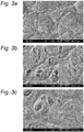
- Fig. 3a is showing the reference SEM image of the top-side Reference Example 6 and Fig. 3b and 3c show respectively top- and bottom SEM image of inventive Example 1.
- Recipe solution C1 and A1 were prepared by mixing the ingredients expressed as wt.% as shown in Table 2 and 3.
- Table 2 - Recipe C1 (for a cationic membrane)
- Table 3 - Recipe A1 (for an anionic membrane)
- the samples were radiation cured using a Light Hammer LH6 from Fusion UV Systems fitted with a D-bulb working at 100% intensity with a speed of 30 m/min (single pass). The exposure time was 0.47 seconds.
- Fig. 4a shows a scanning electron microscope image of a cross section of a comparative membrane prepared using a corona plasma treatment (Reference Example RE4) and Fig. 4b shows a membrane according to an embodiment of the present invention (Example 1), in each case using Recipe A1.
Landscapes
- Chemical & Material Sciences (AREA)
- Engineering & Computer Science (AREA)
- Physics & Mathematics (AREA)
- Plasma & Fusion (AREA)
- Analytical Chemistry (AREA)
- Chemical Kinetics & Catalysis (AREA)
- Power Engineering (AREA)
- Manufacturing & Machinery (AREA)
- Inorganic Chemistry (AREA)
- Medicinal Chemistry (AREA)
- Polymers & Plastics (AREA)
- Organic Chemistry (AREA)
- Health & Medical Sciences (AREA)
- Separation Using Semi-Permeable Membranes (AREA)
- Treatments Of Macromolecular Shaped Articles (AREA)
- Plasma Technology (AREA)
Description
- This invention relates to a method of treating a substrate, comprising providing a treatment space between at least two opposing electrodes, and filling the treatment space with a gas composition.
- Ion exchange membranes have wide applications including energy storage and conversion, electro-dialysis, separation of ionic species in environmental protection and clean production, and nano- or ultra-filtration. Most of ion exchange membranes are composed of functional polymers, in which the charged groups are chemically bonded to the polymer chains.
- The charged groups are -SO3 -, -COO-, -PO3 2-, -PO3H-, and -C6H4O-, etc. for cat-ion exchange membranes and -NH3 +, -NRH2 +, -NR3 +, -PR3 +, and -SR2 +, etc. for anion exchange membranes. Cat-ion exchange membranes contain negatively charged groups attached to the membrane backbone and allow the passage of cations but reject anions, while anion exchange membranes containing positively charged groups allow the passage of anions but reject cations.
- In order to yield long lasting mechanical stable membranes it is advantageous to make the membrane having a porous stable polymer support as substrate and filling the pores with ion exchange material.
- The use of hydrophobic, inert materials as the porous substrate will contribute to enhanced mechanical and chemical stability as hydrophobic materials have minimal swelling in aqueous media. Unfortunately, an inert hydrophobic base membrane is not typically compatible with ion exchange material, which is hydrophilic. Incompatibility between the materials of the base membrane and the ion exchange materials can cause membrane defects, such as holes in the membrane, because there is poor interfacial interaction between the base membrane and the ion exchange materials.
- In the prior art, see for example the document
US 2002/132107 A1 , the use of plasma or corona treatments are disclosed, however, the methods described therein have the disadvantage that only the surface of the porous substrate is affected and not throughout the total porous substrate. As a result, there is a need for improved uniformly activated composite membrane materials compatible with the ion exchange material. - The present invention is defined by by the appended claims and seeks to provide a method of treating a porous substrate in order to allow manufacturing membranes in an efficient and cost-effective manner, and which solves the problems described above.
- In an embodiment, a method according to the preamble above is provided, further comprising placing the substrate, which is a porous substrate in the treatment space, generating an atmospheric pressure glow (APG) discharge plasma between the at least two opposing electrodes, subjecting the porous substrate to the atmospheric pressure glow discharge plasma, thereby creating micro-pores uniformly throughout the porous substrate. The effect of the APG treatment is that the micro-pores are uniformly hydrophilic, allowing e.g. an easy impregnation step with (hydrophilic) ion exchange material.
- The atmospheric pressure glow discharge plasma in the treatment space has a specific energy of 10 J/cm2 or higher. This specific energy is advantageous because it can allow the particles in the plasma to penetrate sufficiently deep into the porous substrate.
- In one embodiment, the porous substrate comprises a polymer support, e.g. of polyolefin, polyamide, polyester, polyether, acrylic or methacrylic polymers, polystyrene, polyurethane or cellulosic polymer or combinations thereof.
- The method further comprises impregnating the substrate with ion exchange material. Thus, an ion exchange membrane is provided. The method may further comprise radiation curing of the porous substrate resulting in a ready to use membrane.
- Heating the porous substrate to a temperature between 20 and 50°C is provided for in a further embodiment, resulting in a more efficient treatment of the porous substrate. Heating may be provided in a direct manner, or in an indirect manner, e.g. using heating of the electrodes.
- In a further embodiment, the gas composition comprises a reactive gas and an inert or noble gas. For example, preferably the gas composition comprises 0.1 to 21 vol.% oxygen. This provides sufficient reactive particles in the APG plasma to treat the porous substrate entirely without damaging the substrate. In even further embodiments, the APG treatment is further enhanced by using an inert gas in the gas composition, e.g. nitrogen. Preferably the gas composition comprises 79 to 99.9 vol.% nitrogen, especially 95 to 99.9 vol.% nitrogen.
- The micro-pores preferably are between 0.1 µm and 10µm in size (i.e. average diameter) in a further embodiment (after the APG step). The porous substrate may have a porosity between 25 and 95%. The porosity of the substrate is defined as the percentage of the volume of all the pores in the substrate with respect to the whole volume of the substrate, including the pores.
- The porosity values may be obtained by performing the following equation:

- BW is the weight of the porous substrate in g/m2;
- thickness is the average thickness of the porous substrate in µm; and
- P is the density of the porous substrate in g/cm3.
- In successfully tested exemplary embodiments, substrates were used having a thickness of 60 µm or less, e.g. 25µm.
- In a further aspect, the present invention relates to the use of a membrane comprising a substrate obtained by one of the present invention method embodiments. Such membranes can e.g. be used in energy storage and energy conversion, electro-dialysis, separation of ionic species e.g. in environmental protection and clean production, and nano- or ultra-filtration.
- The present invention will be explained in further detail hereinafter based on a number of exemplary embodiments with reference to the drawings, wherein:
-
Fig 1 is a schematic view of the atmospheric pressure glow discharge plasma according to an embodiment of the present invention; -
Fig. 2a shows a schematic detail view of an electrode structure of the plasma generation apparatus according to an embodiment of the present invention; -
Fig. 2b shows a schematic view in more detail of a further embodiment of the electrode structure; -
Fig. 3a shows a top view SEM image of an untreated Solupor™ 10P05A substrate; -
Fig. 3b shows a top-side SEM image of a plasma treated Solupor™ 10P05A substrate according to an embodiment of the present invention; -
Fig. 3c shows a bottom-side SEM image of a plasma treated Solupor™ 10P05A substrate according to an embodiment of the present invention; -
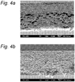
Fig. 4a shows a reference example of a cross-cut of a membrane of the present invention; -
Fig. 4b shows a cross-cut of a membrane according to an embodiment of the present invention; -
Fig. 5 is a schematic overview of an alternative plasma apparatus according to an embodiment of the present invention. -
Fig. 1 shows a schematic view of an embodiment of aplasma treatment apparatus 10 in which the present invention may be applied. Atreatment space 5, which may be a treatment space within an enclosure 1, or atreatment space 5 with an open structure, comprises twoelectrodes electrodes electrodes electrodes electrodes treatment space 5. As indicated in the embodiments ofFig. 1 the power supply 4 comprises anAC power source 20 connected to astabilisation circuit 21. - The
plasma treatment apparatus 10 is arranged to provide a uniform APG plasma, as opposed to other types of plasma, which are non-uniform (e.g. a corona discharge, or other types of filamentary discharges). -
Fig. 1 shows a variant wherein oneporous substrate 11 is treated. However, other treatments are possible like for example shown inFig. 2a , where twoporous substrates 11 are treated simultaneously, or in the example ofFig. 5 , where onesubstrate 11 is treated while being supported by a substrate 7 acting as carrier. - In the
treatment space 5, a combination of gasses is introduced from agas supply device 8. Thegas supply device 8 may be provided with storage, supply and mixing components as known to the skilled person. As shown inFig. 1 a gas supply inlet may be provided to direct the gasses to thetreatment space 5. - Further a
side tab 12 may be used to close off thetreatment space 5 on one side as is shown inFig. 1 however the other side may be closed too which is not shown here. - The
plasma treatment apparatus 10 is used according to the present invention embodiments, to treat at least oneporous substrate 11 in order to make it suited for use in e.g. an ion exchange membrane, e.g. by filling the pores with ion exchange materials. - The composite membrane then includes a porous base substrate or
base membrane 11, which has a plurality of pores. In one embodiment, thebase substrate 11 has a three-dimensional matrix or lattice type structure with a plurality of nodes interconnected by a plurality of fibrils. The interconnections between the nodes and fibrils define the pores in the base membrane, which are open spaces or voids. The surfaces of the nodes and fibrils define numerous interconnecting pores that extend completely through the membrane. - The pore sizes in the
base membrane 11 may be any size. In one embodiment, the average pore size of the pores in the base membrane is micro-porous. In another embodiment, the average pore size is in the range of about 0.01 µm to about 10 µm, and in another embodiment, the average pore size is in the range of about 0.1 µm to about 5.0 µm. - Porosity of the
porous substrate 11, may be in the range from 25 to 95%. The porosity of theporous substrate 11, is defined as the percentage of the volume of all the pores in the substrate with respect to the whole volume of the substrate. - The
base membrane 11 may be any material or blend of materials that is suitable for forming a base membrane with an open pore structure. In one embodiment, the base membrane material includes, but is not limited to, polyolefin, polyamide, polyester, polyether, acrylic and methacrylic polymers, polystyrene, polyurethane and cellulosic polymer and combinations thereof. - In an embodiment, the porous substrate are hydrophobic porous membranes made from hydrophobic materials like polyethylene (PE), polypropylene (PP), poly(vinylidene-difluoride) (PVDF), polytrifluorochloroethylene (PTFCE), polytetrafluoroethylene (PTFE), and polysulfone (PS).
- In an exemplary embodiment, the base substrate is a microporous polyethylene film from Lydall from the Solupor™ series like for example Solupor™ 3P07A, 5P09A,7P03A, 7P07C, 10P05A, 14P01E, 16P05A and 16P10A. Solupor™ materials are produced by extrusion of a solvent together with a solution comprising a mixture of UHMW and HMW polyethylene, followed by drying the resulting tape and biaxial stretching of the tape, resulting in a micro-porous membrane. This process is described in more detail in
EP 504,954 EP 0,504,954 describes some of those techniques. Solupor™ materials are commercially available in a range of porosities. - In one embodiment, the
base substrate 11 has a thickness of 60 µm. In another embodiment, the base substrate orbase membrane 11, has a thickness of about 25 µm or more. - The gases used in the
plasma treatment apparatus 10 may vary depending on the intended application. The gasses can be selected for example from noble gases like argon and the like, an inert gas like nitrogen, and reactive gases like oxygen, hydrogen, carbon(di)oxide, nitrogen-oxide combinations of these reactive gases and inert or noble gases. - Both
electrodes Fig. 2a/b ) or both being roll-electrodes as can be seen in the embodiments ofFig. 5 . Also different configurations may be applied using a flat and a roll-electrode opposing each other. - In the embodiment depicted in
Fig. 5 , a roll-electrode electrodes electrodes gas supply device 8 directs a suitable gas composition into thetreatment space 5 interposed between therotating electrodes - In the embodiment shown, three
substrates 6, 7, 11 are provided to thetreatment space 5 simultaneously by rotatingsupply drums Substrates 7 and 11 may be first laminated usinglamination roller 25, which allows thetop substrate 11 and other substrate 6 to be treated simultaneously in thetreatment space 5 and subjected to an atmospheric pressure glow discharge plasma, thereby creating micro-pores throughout thetop substrate 11 and substrate 6. After treatment, the substrate 6, andlaminated substrate 7, 11 are received on storage drums 24. The embodiment inFig. 5 is particularly suitable for mass production of the composite membranes as thesubstrates 6, 7, 11 are supplied in a continuous manner. - In a further embodiment three substrates are provided to the
treatment space 5 simultaneously as shown inFig. 5 without a lamination step and substrate 7 is just acting as carrier substrate for theporous substrate 11. Substrates 6, 7 are brought in contact with therespective electrodes Fig. 2b ). Bothsubstrates 7, 11 are received after the atmospheric pressure glow discharge plasma treatment on a receivingroll 24. After an unwinding step (which is not shown here) thesubstrates 7, 11 may be separated from each other. This embodiment is particularly suitable to control the dielectric barrier and thereby creating a stable and uniform plasma. -
Fig. 2a and 2b show two embodiments of a part of theplasma treatment apparatus 10 with different electrode configurations. Bothelectrodes dielectric barrier layer Fig. 2a . Thedielectric layer 2a on thefirst electrode 2 has a thickness of d1 (mm), and thedielectric layer 3a on thesecond electrode 3 has a thickness of d2 (mm). In operation, the total dielectric distance d of the electrode configuration also includes the thickness of the (one or two)substrates 11 to be treated, indicated by f1 (mm) and f2 (mm) inFig. 2a . Thus, the total dielectric thickness of the dielectric barrier in thetreatment space 5 between the at least two opposing electrodes (2, 3) equals d = d1+f1+f2+d2. - In the further embodiment shown in
Fig. 2b , both d1 and d2 are 0 and the only dielectric material forming the dielectric barrier is a substrate 6, 7 itself in contact with therespective electrode electrode 2 is not covered with a dielectric material it is possible to obtain a stable atmospheric glow discharge plasma in thetreatment space 5. - In the embodiment shown in
Fig. 5 and described above theelectrodes substrates 6, 7, 11. In this particular case as shown the total dielectric thickness of the dielectric barrier in thetreatment space 5 between the at least two opposingelectrodes - The gap distance g as shown in
Fig. 2a and 2b indicates the (smallest) gap between theelectrodes substrates 6, 7, 11 simultaneously and of the thickness and material of the substrates. - The dimensions of the
electrodes dielectric barrier layers electrodes WO2009104957 of the applicant, which is herein incorporated by reference. - In the embodiments described above, the power supply 4 can be a power supply providing a wide range of frequencies. For example, it can provide a low frequency (f = 10-500 kHz) electrical signal during the on-time. It can also provide a high frequency electrical signal for example f = 450 kHz up to 30 MHz. Also other frequencies can be provided like from 450 kHz to 1 MHz or from 1 to 20 MHz and the like. The on-time may vary from very short, e.g. 20 µs, to short, e.g. 500 µs or as long as 2 minutes or even continuous. The on-time effectively results in a pulse train having a series of sine wave periods at the operating frequency, with a total duration of the on-time. According to the invention good results have been obtained using a duty cycle of 40% up to 100%.
- Very good results can now be obtained by using an atmospheric pressure glow discharge (APG) plasma. Until recently these plasma's suffered from bad stability, but using the stabilization circuits as described in e.g.
US-6774569 ,EP-A-1383359 ,EP-A-1547123 andEP-A-1626613 (which are incorporated herein by reference), very stable APG plasmas can be obtained. In general, these plasmas are stabilized by a stabilization circuit 21 (see description ofFig. 1 ) counteracting local instabilities in the plasma. Using thestabilization circuit 21 in combination with theAC power source 20 in the power supply 4 for theplasma generating apparatus 10 results in a controlled and stable plasma, without streamers, filamentary discharges or other imperfections. - Although oxygen as a reactive gas has a many advantages in for example surface modification uses or in uses where oxidative processes occur, other reactive gases might be used also, such as hydrogen, carbon dioxide, ammonia, oxides of nitrogen, and the like.
- In the present invention, one or more carrier gasses are used chosen from the group comprising argon, nitrogen, or a combination of both. However, also other inert gasses (e.g. helium or argon) or combinations of inert gasses may be used.
- In an embodiment the gas composition in the
treatment space 5 comprises nitrogen in the range 79 to 99.9% and oxygen in the range of 0.1 to 21% vol.%, e,g, 95 to 99.9% and oxygen in the range of 0.1 to 5 vol.%. Oxygen concentrations higher than 21 vol.% may result in damage to theporous substrate 11. - In a further embodiment, the
substrate 11 is heated during the plasma treatment by e.g. heating theelectrodes heated electrodes 2, 3 (and thus the substrate 6, 7, 11) is typically between 20 and 150°C. Examples of such heating embodiments may be found inWO2008147184 from the same applicant, which is herein incorporated by reference. Other heating implementations, direct or indirect may be contemplated in further embodiments. - After the plasma treatment according to the present invention, the
porous substrate 11 is volumetrically compatibilized (i.e. uniformly throughout the substrate and not only the top surface of the substrate), which is thought to be the result of volumetric hydrophylization of the micro-pores by oxidation and production of OH-groups as well as to uniform enlargement of the pores of themicro-porous substrate 11 by the plasma treatment. - After the plasma treatment step described above the activated
porous substrate 11 is immersed in or impregnated with the ion exchange material, in order to obtain the actual ion exchange membrane. The impregnation step is done via techniques known as such in the art. Various options are available for applying the ion exchange solution components to the plasma treatedporous substrates 11 which may include e.g. dip, spray, bar coating steps etc. - After the impregnation the resulting membranes were radiation cured using UV-light to obtain the final membrane ready for use.
- As a
porous substrate 11 two grades of Solupor™ materials were tested. - As substrates 6 and 7 PET foil type Astera X063.004 from Agfa was used with a thickness of 63µm.
- P1: Solupor™ 10P05A: porosity 83% /thickness 60µm /mean pore size is 0.5µm.
- P2: Solupor™ 14P01E: porosity 40% /thickness 25µm /mean pore size is 0.1 µm.
- Both porous substrates 11 (P1, P2) were separately treated on top of a supporting carrier PET foil 7 using an atmospheric pressure glow discharge plasma apparatus as shown in
Fig. 5 having a treatment width of 150 mm and a gaseous gap of 0.5 mm at a controlled electrode temperature of 30°C at a web speed of 1 m/min. The substrate, gas composition and the power density was varied according to the Table 1 shown below. The plasma treated substrate on the receivingroll 24 was unwound and separated into two separatedsubstrates 7 and 11.Table 1 Example Porous substrate gas composition and flows [slm] excitation (overall power/pulsing) Specific energy [J/cm2] RE1 P1 Ar 200 W, CW@ 7.9 10 slm RE2 P2 Ar/O2 200 W, CW@ 7.9 10/1.0 slm RE3 P1 Ar/O2 200 W, CW@ 5.6 10/1.0 slm 1 P1 N2/O2 300 W (pulsed, 50% DC$) 12 15/1.0 slm 2 P1 N2/O2 600 W (pulsed, 90% DC$) 23.7 15/0.1 slm 3 P1 N2/O2 300 W (pulsed, 50% DC$) 12 15/0.1 slm 4 P1 N2/O2 300 W (pulsed, 50% DC$) 12 15/0.05 slm 5 P2 N2/O2 300 W (pulsed, 50% DC$) 12 15/0.05 slm RE8 P1 N2 600 W (pulsed, 90% DC$) 23.7 15 slm RE9 P1 N2/O2 300 W (pulsed, 50% DC$) 12 15/4.0 slm DC$ means duty cycle
CW@ means continuous wave
RE means Reference Example
Note: Table 1 lists Examples 1 to 5 and Reference Examples 8 and 9 which were treated in the atmospheric pressure glow discharge plasma as shown inFig.5 . Reference Examples RE4 to RE7 are described below. - The two porous substrates P1, P2 (Solupor™ 10P05A and 14P01E) used above were Corona treated in air using a Softal™ corona VTG250 apparatus at a specific energy of 16 J/cm2 using ceramic electrodes coupled to a Softal™ VTG3005 generator.
- The same porous substrates as above however untreated (in plasma or corona environment) were used as
reference samples 4 and 5. - Before the impregnation step, all five Examples and nine Reference Examples were checked by a Jeol JSM-6330F Field Emission Scanning Electron Microscope (SEM) SE detector/5kV Accelerating Voltage/15 mm Working Distance/
Aperture 2/Pt-coating, 10 nm thickness/enlargement 2000x). -
Fig. 3a is showing the reference SEM image of the top-side Reference Example 6 andFig. 3b and 3c show respectively top- and bottom SEM image of inventive Example 1. - All fourteen samples of above (i.e. Examples 1 to 5 and Reference Examples RE1 to RE9) were impregnated with two kinds of recipes (one C1 recipe for making a cationic membrane and one A1 recipe for making an an-ionic membrane) resulting in 28 samples by a dip-coating of all 14 samples in a bath containing the C1 or A1 recipe-solutions.
- Recipe solution C1 and A1 were prepared by mixing the ingredients expressed as wt.% as shown in Table 2 and 3.
Table 2 - Recipe C1 (for a cationic membrane) Ingredient wt.% ATMAC 27.6 MBA 20.6 Water 21.3 IPA 8.9 LiNO3 21.1 MEHQ 0.05 Darocur™ 1173 0.45 Table 3 - Recipe A1 (for an anionic membrane) Ingredient wt.% AMPS 50.3 MBA 12.0 Water 28.4 IPA 8.3 Genorad™16 0.5 Darocur™ 1173 0.5 - AMPS
- is 2-Acryloylamido-2-methylpropanesulfonic acid from Hang-Zhou (China) (a curable compound having one ethylenically unsaturated group), having a molecular weight of 207.2.
- MBA
- is N,N'-methylene bisacrylamide from Sigma Aldrich (a curable compound comprising at least two (meth)acrylic groups and being free from quaternary ammonium groups), having a molecular weight of 154.2.
- ATMAC
- is 3-acrylamidopropyl-trimethylammonium chloride from Kohjin (a curable compound having one ethylenically unsaturated group), having a molecular weight of 206.7.
- IPA
- is 2-propanol from Shell (a solvent).
- MEHQ
- is hydroquinone mono methyl ether (a polymerization inhibitor).
- LiNO3
- is lithium nitrate.
- IPA
- is 2-propanol from Shell.
- Genorad™ 16
- is a polymerization inhibitor.
- Darocur™ 1173
- is a photo initiator.
- After impregnation the samples were radiation cured using a Light Hammer LH6 from Fusion UV Systems fitted with a D-bulb working at 100% intensity with a speed of 30 m/min (single pass). The exposure time was 0.47 seconds.
- After the impregnation with Recipe A1 and C1, the samples were inspected visually and by SEM images off cross-cuts of the membranes. Table 4 shows the results of these inspections.
Table 4 Damage Impregnation (checked by SEM #) RE1 no no RE2 no/matte surface no RE3 no/matte surface no Example 1 no yes Example 2 no yes Example 3 no yes Example 4 no yes Example 5 no yes RE4 no no RE5 no no RE6 - no RE7 - no RE8 (0% oxygen) no no RE9 (>21 vol.% oxygen) yes yes #: the impregnation evaluation was performed using a Jeol JSM-6330F Field Emission Scanning Electron Microscope (SEM) SE detector/5kV Accelerating Voltage/15 mm Working Distance/ Aperture 2/Pt-coating, 10 nm thickness/enlargement 1000x) -
Fig. 4a shows a scanning electron microscope image of a cross section of a comparative membrane prepared using a corona plasma treatment (Reference Example RE4) andFig. 4b shows a membrane according to an embodiment of the present invention (Example 1), in each case using Recipe A1. - From the Examples 1-5 shown in Tables 1 and 4, it can be inferred that the compatabilitization due to uniform and volumetric impregnation is the result of the plasma treatment according to the present invention. In particular, Reference Examples RE1 and RE8 lack oxygen in the gas composition. Reference Example RE9 shows that more than 21 vol.% oxygen in the gas composition damaged the membrane. Furthermore, the specific energy of the atmospheric pressure glow discharge plasma in the treatment space was rather low for Reference Examples RE2-3, i.e. less than 10 J/cm2. Reference Examples RE6 and RE7 indicate that the corona treatment does not allow for proper impregnation of the porous substrate, hence further proving the advantages of the present invention.
- The present invention embodiments have been described above with reference to a number of exemplary embodiments as shown in and described with reference to the drawings. Modifications and alternative implementations of some parts or elements are possible, and are included in the scope of protection as defined in the appended claims.
Claims (15)
- A method of treating a substrate, comprising:providing a treatment space between at least two opposing electrodes, filling the treatment space with a gas composition, placing the substrate, which is a porous substrate, in the treatment space,generating an atmospheric pressure glow discharge plasma between the at least two opposing electrodes, andsubjecting the porous substrate to the atmospheric pressure glow discharge plasma, thereby creating micro-pores uniformly throughout the porous substrate,wherein the treatment space comprises oxygen in the range of 0.1 to 21% vol.%, characterised in that the atmospheric pressure glow discharge plasma in the treatment space has a specific energy of 10 J/cm2 or higher, and in that the method is performed with a duty cycle of 40% to 100%.
- A method according to claim 1 which is powered by a power supply comprises an AC power source connected to a stabilisation circuit.
- A method according to claim 1 or 2 which is performed using pulsed power.
- A method according to claim 1, 2 or 3, wherein the porous substrate comprises a polymer support.
- A method according to any one of claims 1-4, further comprising impregnating the substrate with ion exchange material.
- A method according to any one of claims 1-5, further comprising radiation curing of the porous substrate.
- A method according to any one of claims 1-6, further comprising heating the porous substrate to a temperature between 20 and 150°C.
- A method according to any one of claims 1-7, wherein the treatment space comprises nitrogen in the range 79 to 99.9%.
- A method according to claim 8, wherein the treatment space comprises nitrogen in the range 95 to 99.9%.
- A method according to any one of claims 1-9, wherein the micro-pores have an average diameter of between 0.1µm and 10µm.
- A method according to any one of claims 1-10, wherein the porous substrate has a porosity between 25 and 95%.
- A method according to any one of claims 1-11, wherein the substrate has a thickness of 60 µm or less.
- A method according to any one of claims 1-12, wherein a carrier substrate is positioned in contact the electrodes.
- A method according to any one of claims 1-13, wherein the treatment space comprises oxygen in the range 0.1 to 5 vol. %.
- Use of a membrane comprising a substrate obtainable by a method according to any one of the preceding claims for energy storage, energy conversion, electro-dialysis, separation of ionic species, nano-filtration or ultra-filtration.
Applications Claiming Priority (2)
| Application Number | Priority Date | Filing Date | Title |
|---|---|---|---|
| GBGB1215098.3A GB201215098D0 (en) | 2012-08-24 | 2012-08-24 | Method of treating a porous substrate and manufacture of a membrane |
| PCT/GB2013/051991 WO2014029963A1 (en) | 2012-08-24 | 2013-07-25 | Method of treating a porous substrate and manufacture of a membrane |
Publications (2)
| Publication Number | Publication Date |
|---|---|
| EP2888029A1 EP2888029A1 (en) | 2015-07-01 |
| EP2888029B1 true EP2888029B1 (en) | 2018-11-07 |
Family
ID=47045342
Family Applications (1)
| Application Number | Title | Priority Date | Filing Date |
|---|---|---|---|
| EP13742712.6A Not-in-force EP2888029B1 (en) | 2012-08-24 | 2013-07-25 | Method of treating a porous substrate and manufacture of a membrane |
Country Status (5)
| Country | Link |
|---|---|
| US (1) | US20150231575A1 (en) |
| EP (1) | EP2888029B1 (en) |
| JP (1) | JP6170559B2 (en) |
| GB (1) | GB201215098D0 (en) |
| WO (1) | WO2014029963A1 (en) |
Families Citing this family (2)
| Publication number | Priority date | Publication date | Assignee | Title |
|---|---|---|---|---|
| KR102386179B1 (en) * | 2014-06-30 | 2022-04-14 | 쓰리엠 이노베이티브 프로퍼티즈 캄파니 | Asymmetric articles with a porous substrate and a polymeric coating extending into the substrate and methods of making the same |
| CN107530605B (en) | 2015-04-22 | 2021-05-25 | 阿科玛股份有限公司 | Porous Articles with Submicron Particles of Polymer Binder |
Family Cites Families (10)
| Publication number | Priority date | Publication date | Assignee | Title |
|---|---|---|---|---|
| JP3453200B2 (en) * | 1994-10-26 | 2003-10-06 | 三菱重工業株式会社 | Method for producing surface-modified conductive polymer compound film |
| JPH11300180A (en) * | 1998-02-20 | 1999-11-02 | Mitsubishi Chemical Corp | Porous resin film |
| US20020132107A1 (en) * | 1998-05-15 | 2002-09-19 | O'brien Jeffrey James | Porous polyethylene membrane |
| US6118218A (en) * | 1999-02-01 | 2000-09-12 | Sigma Technologies International, Inc. | Steady-state glow-discharge plasma at atmospheric pressure |
| JP2000317280A (en) * | 1999-05-06 | 2000-11-21 | Teijin Ltd | Filter using ultra high molecular weight polyethylene porous membrane as filtration medium |
| JP2001214366A (en) * | 1999-07-15 | 2001-08-07 | Sekisui Chem Co Ltd | Nonwoven fabric and method for manufacturing the same, and separator for secondary battery using the nonwoven fabric and method for manufacturing the same |
| JP4930913B2 (en) * | 2005-09-12 | 2012-05-16 | 東レバッテリーセパレータフィルム合同会社 | Plasma processing method and processing apparatus for porous material |
| US7963401B2 (en) * | 2006-04-03 | 2011-06-21 | Entegris, Inc. | Atmospheric pressure microwave plasma treated porous membranes |
| JP2012517530A (en) * | 2009-02-12 | 2012-08-02 | フジフィルム・マニュファクチュアリング・ヨーロッパ・ベスローテン・フエンノートシャップ | Two-layer barrier on polymer substrate |
| GB0921949D0 (en) * | 2009-12-16 | 2010-02-03 | Fujifilm Mfg Europe Bv | Curable compositions and membranes |
-
2012
- 2012-08-24 GB GBGB1215098.3A patent/GB201215098D0/en not_active Ceased
-
2013
- 2013-07-25 EP EP13742712.6A patent/EP2888029B1/en not_active Not-in-force
- 2013-07-25 JP JP2015527960A patent/JP6170559B2/en not_active Expired - Fee Related
- 2013-07-25 US US14/422,709 patent/US20150231575A1/en not_active Abandoned
- 2013-07-25 WO PCT/GB2013/051991 patent/WO2014029963A1/en not_active Ceased
Non-Patent Citations (1)
| Title |
|---|
| None * |
Also Published As
| Publication number | Publication date |
|---|---|
| WO2014029963A1 (en) | 2014-02-27 |
| US20150231575A1 (en) | 2015-08-20 |
| GB201215098D0 (en) | 2012-10-10 |
| JP6170559B2 (en) | 2017-07-26 |
| EP2888029A1 (en) | 2015-07-01 |
| JP2015533626A (en) | 2015-11-26 |
Similar Documents
| Publication | Publication Date | Title |
|---|---|---|
| US12272496B2 (en) | Capacitors, electrodes, reduced graphene oxide and methods and apparatuses of manufacture | |
| US6734386B1 (en) | Method for rendering PVDF membrane hydrophilic | |
| EP2734291B1 (en) | Membranes made from curable compositions | |
| EP2303437B1 (en) | Method of forming an asymmetric membrane | |
| EP1678245B1 (en) | Microporous pvdf films and method of manufacturing | |
| TWI500447B (en) | Composition comprising a multi-layer halogenated polyolefin microporous membrane, a filter comprising it and a method of making the same | |
| EP2764908A1 (en) | Gas separation membrane, method of producing the same, and gas separation membrane module using the same | |
| Li et al. | Hydrophilic porous poly (sulfone) membranes modified by UV-initiated polymerization for vanadium flow battery application | |
| EP3245234B1 (en) | Curable compositions and membranes | |
| EP2412755B1 (en) | Process for producing porous stretched polytetrafluoroethylene film or tape having catalyst particles supported thereon, film and filter for ozone removal | |
| EP2060599A1 (en) | Microporous polyethylene film with improved strength, permeability and surface energy | |
| EP3322748B1 (en) | Ion exchange membranes | |
| KR101754658B1 (en) | manufacturing method of PTFE electrolyte membrane for fuel cell | |
| DE69717707T2 (en) | Process for the treatment of external and internal surfaces of non-conductive porous materials | |
| EP3789440A1 (en) | Pore-filled ion exchange polyelectrolyte composite membrane from which surface ion exchange polyelectrolyte has been removed and method for manufacturing same | |
| KR20150023666A (en) | Breathable electrode and method for use in water splitting | |
| JP2010149011A (en) | Method of manufacturing coating film and method of manufacturing separator for non-aqueous secondary battery | |
| EP3088451B1 (en) | Plasma assisted hydrophilicity enhancement of polymer materials | |
| US20150231575A1 (en) | Method of Treating a Porous Substrate and Manufacture of a Membrane | |
| JPH07247377A (en) | Method for producing surface-modified fluororesin | |
| EP3322749B1 (en) | Ion exchange membranes | |
| US12251693B2 (en) | Surface modified membranes | |
| JPS6152175B2 (en) | ||
| US20150318527A1 (en) | Plasma treatment of an electrochemical membrane | |
| JP4132354B2 (en) | Novel sulfur-containing atomic group-introducing porous body, method for introducing sulfur-containing atomic group to the entire surface of the porous body, and battery separator |
Legal Events
| Date | Code | Title | Description |
|---|---|---|---|
| PUAI | Public reference made under article 153(3) epc to a published international application that has entered the european phase |
Free format text: ORIGINAL CODE: 0009012 |
|
| 17P | Request for examination filed |
Effective date: 20150130 |
|
| AK | Designated contracting states |
Kind code of ref document: A1 Designated state(s): AL AT BE BG CH CY CZ DE DK EE ES FI FR GB GR HR HU IE IS IT LI LT LU LV MC MK MT NL NO PL PT RO RS SE SI SK SM TR |
|
| AX | Request for extension of the european patent |
Extension state: BA ME |
|
| DAX | Request for extension of the european patent (deleted) | ||
| GRAP | Despatch of communication of intention to grant a patent |
Free format text: ORIGINAL CODE: EPIDOSNIGR1 |
|
| STAA | Information on the status of an ep patent application or granted ep patent |
Free format text: STATUS: GRANT OF PATENT IS INTENDED |
|
| RIC1 | Information provided on ipc code assigned before grant |
Ipc: B01D 69/10 20060101ALI20180710BHEP Ipc: B01D 67/00 20060101AFI20180710BHEP Ipc: H01J 37/32 20060101ALI20180710BHEP |
|
| INTG | Intention to grant announced |
Effective date: 20180731 |
|
| GRAS | Grant fee paid |
Free format text: ORIGINAL CODE: EPIDOSNIGR3 |
|
| GRAA | (expected) grant |
Free format text: ORIGINAL CODE: 0009210 |
|
| STAA | Information on the status of an ep patent application or granted ep patent |
Free format text: STATUS: THE PATENT HAS BEEN GRANTED |
|
| AK | Designated contracting states |
Kind code of ref document: B1 Designated state(s): AL AT BE BG CH CY CZ DE DK EE ES FI FR GB GR HR HU IE IS IT LI LT LU LV MC MK MT NL NO PL PT RO RS SE SI SK SM TR |
|
| REG | Reference to a national code |
Ref country code: GB Ref legal event code: FG4D |
|
| REG | Reference to a national code |
Ref country code: CH Ref legal event code: EP Ref country code: AT Ref legal event code: REF Ref document number: 1061405 Country of ref document: AT Kind code of ref document: T Effective date: 20181115 |
|
| REG | Reference to a national code |
Ref country code: IE Ref legal event code: FG4D |
|
| REG | Reference to a national code |
Ref country code: DE Ref legal event code: R096 Ref document number: 602013046306 Country of ref document: DE |
|
| REG | Reference to a national code |
Ref country code: NL Ref legal event code: FP |
|
| REG | Reference to a national code |
Ref country code: LT Ref legal event code: MG4D |
|
| REG | Reference to a national code |
Ref country code: AT Ref legal event code: MK05 Ref document number: 1061405 Country of ref document: AT Kind code of ref document: T Effective date: 20181107 |
|
| PG25 | Lapsed in a contracting state [announced via postgrant information from national office to epo] |
Ref country code: AT Free format text: LAPSE BECAUSE OF FAILURE TO SUBMIT A TRANSLATION OF THE DESCRIPTION OR TO PAY THE FEE WITHIN THE PRESCRIBED TIME-LIMIT Effective date: 20181107 Ref country code: ES Free format text: LAPSE BECAUSE OF FAILURE TO SUBMIT A TRANSLATION OF THE DESCRIPTION OR TO PAY THE FEE WITHIN THE PRESCRIBED TIME-LIMIT Effective date: 20181107 Ref country code: HR Free format text: LAPSE BECAUSE OF FAILURE TO SUBMIT A TRANSLATION OF THE DESCRIPTION OR TO PAY THE FEE WITHIN THE PRESCRIBED TIME-LIMIT Effective date: 20181107 Ref country code: LV Free format text: LAPSE BECAUSE OF FAILURE TO SUBMIT A TRANSLATION OF THE DESCRIPTION OR TO PAY THE FEE WITHIN THE PRESCRIBED TIME-LIMIT Effective date: 20181107 Ref country code: FI Free format text: LAPSE BECAUSE OF FAILURE TO SUBMIT A TRANSLATION OF THE DESCRIPTION OR TO PAY THE FEE WITHIN THE PRESCRIBED TIME-LIMIT Effective date: 20181107 Ref country code: BG Free format text: LAPSE BECAUSE OF FAILURE TO SUBMIT A TRANSLATION OF THE DESCRIPTION OR TO PAY THE FEE WITHIN THE PRESCRIBED TIME-LIMIT Effective date: 20190207 Ref country code: NO Free format text: LAPSE BECAUSE OF FAILURE TO SUBMIT A TRANSLATION OF THE DESCRIPTION OR TO PAY THE FEE WITHIN THE PRESCRIBED TIME-LIMIT Effective date: 20190207 Ref country code: LT Free format text: LAPSE BECAUSE OF FAILURE TO SUBMIT A TRANSLATION OF THE DESCRIPTION OR TO PAY THE FEE WITHIN THE PRESCRIBED TIME-LIMIT Effective date: 20181107 Ref country code: IS Free format text: LAPSE BECAUSE OF FAILURE TO SUBMIT A TRANSLATION OF THE DESCRIPTION OR TO PAY THE FEE WITHIN THE PRESCRIBED TIME-LIMIT Effective date: 20190307 |
|
| PG25 | Lapsed in a contracting state [announced via postgrant information from national office to epo] |
Ref country code: GR Free format text: LAPSE BECAUSE OF FAILURE TO SUBMIT A TRANSLATION OF THE DESCRIPTION OR TO PAY THE FEE WITHIN THE PRESCRIBED TIME-LIMIT Effective date: 20190208 Ref country code: RS Free format text: LAPSE BECAUSE OF FAILURE TO SUBMIT A TRANSLATION OF THE DESCRIPTION OR TO PAY THE FEE WITHIN THE PRESCRIBED TIME-LIMIT Effective date: 20181107 Ref country code: PT Free format text: LAPSE BECAUSE OF FAILURE TO SUBMIT A TRANSLATION OF THE DESCRIPTION OR TO PAY THE FEE WITHIN THE PRESCRIBED TIME-LIMIT Effective date: 20190307 Ref country code: AL Free format text: LAPSE BECAUSE OF FAILURE TO SUBMIT A TRANSLATION OF THE DESCRIPTION OR TO PAY THE FEE WITHIN THE PRESCRIBED TIME-LIMIT Effective date: 20181107 Ref country code: SE Free format text: LAPSE BECAUSE OF FAILURE TO SUBMIT A TRANSLATION OF THE DESCRIPTION OR TO PAY THE FEE WITHIN THE PRESCRIBED TIME-LIMIT Effective date: 20181107 |
|
| PG25 | Lapsed in a contracting state [announced via postgrant information from national office to epo] |
Ref country code: PL Free format text: LAPSE BECAUSE OF FAILURE TO SUBMIT A TRANSLATION OF THE DESCRIPTION OR TO PAY THE FEE WITHIN THE PRESCRIBED TIME-LIMIT Effective date: 20181107 Ref country code: DK Free format text: LAPSE BECAUSE OF FAILURE TO SUBMIT A TRANSLATION OF THE DESCRIPTION OR TO PAY THE FEE WITHIN THE PRESCRIBED TIME-LIMIT Effective date: 20181107 Ref country code: IT Free format text: LAPSE BECAUSE OF FAILURE TO SUBMIT A TRANSLATION OF THE DESCRIPTION OR TO PAY THE FEE WITHIN THE PRESCRIBED TIME-LIMIT Effective date: 20181107 Ref country code: CZ Free format text: LAPSE BECAUSE OF FAILURE TO SUBMIT A TRANSLATION OF THE DESCRIPTION OR TO PAY THE FEE WITHIN THE PRESCRIBED TIME-LIMIT Effective date: 20181107 |
|
| REG | Reference to a national code |
Ref country code: DE Ref legal event code: R097 Ref document number: 602013046306 Country of ref document: DE |
|
| PG25 | Lapsed in a contracting state [announced via postgrant information from national office to epo] |
Ref country code: SK Free format text: LAPSE BECAUSE OF FAILURE TO SUBMIT A TRANSLATION OF THE DESCRIPTION OR TO PAY THE FEE WITHIN THE PRESCRIBED TIME-LIMIT Effective date: 20181107 Ref country code: EE Free format text: LAPSE BECAUSE OF FAILURE TO SUBMIT A TRANSLATION OF THE DESCRIPTION OR TO PAY THE FEE WITHIN THE PRESCRIBED TIME-LIMIT Effective date: 20181107 Ref country code: SM Free format text: LAPSE BECAUSE OF FAILURE TO SUBMIT A TRANSLATION OF THE DESCRIPTION OR TO PAY THE FEE WITHIN THE PRESCRIBED TIME-LIMIT Effective date: 20181107 Ref country code: RO Free format text: LAPSE BECAUSE OF FAILURE TO SUBMIT A TRANSLATION OF THE DESCRIPTION OR TO PAY THE FEE WITHIN THE PRESCRIBED TIME-LIMIT Effective date: 20181107 |
|
| PLBE | No opposition filed within time limit |
Free format text: ORIGINAL CODE: 0009261 |
|
| STAA | Information on the status of an ep patent application or granted ep patent |
Free format text: STATUS: NO OPPOSITION FILED WITHIN TIME LIMIT |
|
| 26N | No opposition filed |
Effective date: 20190808 |
|
| PG25 | Lapsed in a contracting state [announced via postgrant information from national office to epo] |
Ref country code: SI Free format text: LAPSE BECAUSE OF FAILURE TO SUBMIT A TRANSLATION OF THE DESCRIPTION OR TO PAY THE FEE WITHIN THE PRESCRIBED TIME-LIMIT Effective date: 20181107 |
|
| PG25 | Lapsed in a contracting state [announced via postgrant information from national office to epo] |
Ref country code: MC Free format text: LAPSE BECAUSE OF FAILURE TO SUBMIT A TRANSLATION OF THE DESCRIPTION OR TO PAY THE FEE WITHIN THE PRESCRIBED TIME-LIMIT Effective date: 20181107 |
|
| REG | Reference to a national code |
Ref country code: CH Ref legal event code: PL |
|
| PG25 | Lapsed in a contracting state [announced via postgrant information from national office to epo] |
Ref country code: TR Free format text: LAPSE BECAUSE OF FAILURE TO SUBMIT A TRANSLATION OF THE DESCRIPTION OR TO PAY THE FEE WITHIN THE PRESCRIBED TIME-LIMIT Effective date: 20181107 |
|
| REG | Reference to a national code |
Ref country code: BE Ref legal event code: MM Effective date: 20190731 |
|
| PG25 | Lapsed in a contracting state [announced via postgrant information from national office to epo] |
Ref country code: LI Free format text: LAPSE BECAUSE OF NON-PAYMENT OF DUE FEES Effective date: 20190731 Ref country code: LU Free format text: LAPSE BECAUSE OF NON-PAYMENT OF DUE FEES Effective date: 20190725 Ref country code: CH Free format text: LAPSE BECAUSE OF NON-PAYMENT OF DUE FEES Effective date: 20190731 Ref country code: BE Free format text: LAPSE BECAUSE OF NON-PAYMENT OF DUE FEES Effective date: 20190731 |
|
| PG25 | Lapsed in a contracting state [announced via postgrant information from national office to epo] |
Ref country code: IE Free format text: LAPSE BECAUSE OF NON-PAYMENT OF DUE FEES Effective date: 20190725 |
|
| PGFP | Annual fee paid to national office [announced via postgrant information from national office to epo] |
Ref country code: NL Payment date: 20200726 Year of fee payment: 8 |
|
| PGFP | Annual fee paid to national office [announced via postgrant information from national office to epo] |
Ref country code: GB Payment date: 20200727 Year of fee payment: 8 Ref country code: FR Payment date: 20200728 Year of fee payment: 8 |
|
| PG25 | Lapsed in a contracting state [announced via postgrant information from national office to epo] |
Ref country code: CY Free format text: LAPSE BECAUSE OF FAILURE TO SUBMIT A TRANSLATION OF THE DESCRIPTION OR TO PAY THE FEE WITHIN THE PRESCRIBED TIME-LIMIT Effective date: 20181107 |
|
| PG25 | Lapsed in a contracting state [announced via postgrant information from national office to epo] |
Ref country code: MT Free format text: LAPSE BECAUSE OF FAILURE TO SUBMIT A TRANSLATION OF THE DESCRIPTION OR TO PAY THE FEE WITHIN THE PRESCRIBED TIME-LIMIT Effective date: 20181107 Ref country code: HU Free format text: LAPSE BECAUSE OF FAILURE TO SUBMIT A TRANSLATION OF THE DESCRIPTION OR TO PAY THE FEE WITHIN THE PRESCRIBED TIME-LIMIT; INVALID AB INITIO Effective date: 20130725 |
|
| REG | Reference to a national code |
Ref country code: NL Ref legal event code: MM Effective date: 20210801 |
|
| GBPC | Gb: european patent ceased through non-payment of renewal fee |
Effective date: 20210725 |
|
| PG25 | Lapsed in a contracting state [announced via postgrant information from national office to epo] |
Ref country code: GB Free format text: LAPSE BECAUSE OF NON-PAYMENT OF DUE FEES Effective date: 20210725 |
|
| PG25 | Lapsed in a contracting state [announced via postgrant information from national office to epo] |
Ref country code: NL Free format text: LAPSE BECAUSE OF NON-PAYMENT OF DUE FEES Effective date: 20210801 Ref country code: FR Free format text: LAPSE BECAUSE OF NON-PAYMENT OF DUE FEES Effective date: 20210731 |
|
| PG25 | Lapsed in a contracting state [announced via postgrant information from national office to epo] |
Ref country code: MK Free format text: LAPSE BECAUSE OF FAILURE TO SUBMIT A TRANSLATION OF THE DESCRIPTION OR TO PAY THE FEE WITHIN THE PRESCRIBED TIME-LIMIT Effective date: 20181107 |
|
| PGFP | Annual fee paid to national office [announced via postgrant information from national office to epo] |
Ref country code: DE Payment date: 20230727 Year of fee payment: 11 |
|
| REG | Reference to a national code |
Ref country code: DE Ref legal event code: R119 Ref document number: 602013046306 Country of ref document: DE |
|
| PG25 | Lapsed in a contracting state [announced via postgrant information from national office to epo] |
Ref country code: DE Free format text: LAPSE BECAUSE OF NON-PAYMENT OF DUE FEES Effective date: 20250201 |