EP2887423A1 - Battery module - Google Patents
Battery module Download PDFInfo
- Publication number
- EP2887423A1 EP2887423A1 EP13879477.1A EP13879477A EP2887423A1 EP 2887423 A1 EP2887423 A1 EP 2887423A1 EP 13879477 A EP13879477 A EP 13879477A EP 2887423 A1 EP2887423 A1 EP 2887423A1
- Authority
- EP
- European Patent Office
- Prior art keywords
- fluid port
- tubular wall
- ring shaped
- battery module
- shaped member
- Prior art date
- Legal status (The legal status is an assumption and is not a legal conclusion. Google has not performed a legal analysis and makes no representation as to the accuracy of the status listed.)
- Withdrawn
Links
- 239000012530 fluid Substances 0.000 claims abstract description 94
- 238000001816 cooling Methods 0.000 claims abstract description 46
- 239000000463 material Substances 0.000 claims description 16
- 239000013536 elastomeric material Substances 0.000 claims description 5
- 229910000831 Steel Inorganic materials 0.000 claims description 4
- 239000010959 steel Substances 0.000 claims description 4
- 229920002725 thermoplastic elastomer Polymers 0.000 claims description 3
- 230000008878 coupling Effects 0.000 description 4
- 238000010168 coupling process Methods 0.000 description 4
- 238000005859 coupling reaction Methods 0.000 description 4
- 230000002093 peripheral effect Effects 0.000 description 2
- 239000004033 plastic Substances 0.000 description 2
- 238000007789 sealing Methods 0.000 description 2
- HBBGRARXTFLTSG-UHFFFAOYSA-N Lithium ion Chemical compound [Li+] HBBGRARXTFLTSG-UHFFFAOYSA-N 0.000 description 1
- 230000004075 alteration Effects 0.000 description 1
- 229910001416 lithium ion Inorganic materials 0.000 description 1
- 238000006467 substitution reaction Methods 0.000 description 1
Images






Classifications
-
- H—ELECTRICITY
- H01—ELECTRIC ELEMENTS
- H01M—PROCESSES OR MEANS, e.g. BATTERIES, FOR THE DIRECT CONVERSION OF CHEMICAL ENERGY INTO ELECTRICAL ENERGY
- H01M10/00—Secondary cells; Manufacture thereof
- H01M10/60—Heating or cooling; Temperature control
- H01M10/65—Means for temperature control structurally associated with the cells
- H01M10/655—Solid structures for heat exchange or heat conduction
- H01M10/6556—Solid parts with flow channel passages or pipes for heat exchange
-
- F—MECHANICAL ENGINEERING; LIGHTING; HEATING; WEAPONS; BLASTING
- F28—HEAT EXCHANGE IN GENERAL
- F28F—DETAILS OF HEAT-EXCHANGE AND HEAT-TRANSFER APPARATUS, OF GENERAL APPLICATION
- F28F1/00—Tubular elements; Assemblies of tubular elements
-
- F—MECHANICAL ENGINEERING; LIGHTING; HEATING; WEAPONS; BLASTING
- F28—HEAT EXCHANGE IN GENERAL
- F28F—DETAILS OF HEAT-EXCHANGE AND HEAT-TRANSFER APPARATUS, OF GENERAL APPLICATION
- F28F9/00—Casings; Header boxes; Auxiliary supports for elements; Auxiliary members within casings
- F28F9/02—Header boxes; End plates
- F28F9/0243—Header boxes having a circular cross-section
-
- F—MECHANICAL ENGINEERING; LIGHTING; HEATING; WEAPONS; BLASTING
- F28—HEAT EXCHANGE IN GENERAL
- F28F—DETAILS OF HEAT-EXCHANGE AND HEAT-TRANSFER APPARATUS, OF GENERAL APPLICATION
- F28F9/00—Casings; Header boxes; Auxiliary supports for elements; Auxiliary members within casings
- F28F9/02—Header boxes; End plates
- F28F9/04—Arrangements for sealing elements into header boxes or end plates
- F28F9/06—Arrangements for sealing elements into header boxes or end plates by dismountable joints
- F28F9/14—Arrangements for sealing elements into header boxes or end plates by dismountable joints by force-joining
-
- H—ELECTRICITY
- H01—ELECTRIC ELEMENTS
- H01M—PROCESSES OR MEANS, e.g. BATTERIES, FOR THE DIRECT CONVERSION OF CHEMICAL ENERGY INTO ELECTRICAL ENERGY
- H01M10/00—Secondary cells; Manufacture thereof
- H01M10/60—Heating or cooling; Temperature control
- H01M10/61—Types of temperature control
- H01M10/613—Cooling or keeping cold
-
- H—ELECTRICITY
- H01—ELECTRIC ELEMENTS
- H01M—PROCESSES OR MEANS, e.g. BATTERIES, FOR THE DIRECT CONVERSION OF CHEMICAL ENERGY INTO ELECTRICAL ENERGY
- H01M50/00—Constructional details or processes of manufacture of the non-active parts of electrochemical cells other than fuel cells, e.g. hybrid cells
- H01M50/20—Mountings; Secondary casings or frames; Racks, modules or packs; Suspension devices; Shock absorbers; Transport or carrying devices; Holders
-
- F—MECHANICAL ENGINEERING; LIGHTING; HEATING; WEAPONS; BLASTING
- F28—HEAT EXCHANGE IN GENERAL
- F28D—HEAT-EXCHANGE APPARATUS, NOT PROVIDED FOR IN ANOTHER SUBCLASS, IN WHICH THE HEAT-EXCHANGE MEDIA DO NOT COME INTO DIRECT CONTACT
- F28D21/00—Heat-exchange apparatus not covered by any of the groups F28D1/00 - F28D20/00
- F28D2021/0019—Other heat exchangers for particular applications; Heat exchange systems not otherwise provided for
- F28D2021/0043—Other heat exchangers for particular applications; Heat exchange systems not otherwise provided for for fuel cells
-
- Y—GENERAL TAGGING OF NEW TECHNOLOGICAL DEVELOPMENTS; GENERAL TAGGING OF CROSS-SECTIONAL TECHNOLOGIES SPANNING OVER SEVERAL SECTIONS OF THE IPC; TECHNICAL SUBJECTS COVERED BY FORMER USPC CROSS-REFERENCE ART COLLECTIONS [XRACs] AND DIGESTS
- Y02—TECHNOLOGIES OR APPLICATIONS FOR MITIGATION OR ADAPTATION AGAINST CLIMATE CHANGE
- Y02E—REDUCTION OF GREENHOUSE GAS [GHG] EMISSIONS, RELATED TO ENERGY GENERATION, TRANSMISSION OR DISTRIBUTION
- Y02E60/00—Enabling technologies; Technologies with a potential or indirect contribution to GHG emissions mitigation
- Y02E60/10—Energy storage using batteries
Definitions
- the inventors herein have recognized a need for an improved battery module with a cooling manifold having improved fluid port sealing characteristics.
- the battery module includes a battery cell and a heat exchanger disposed adjacent to the battery cell.
- the battery module further includes a cooling manifold having a tubular wall, a first fluid port, and a ring shaped member.
- the tubular wall defines an interior region and having first and second end portions.
- the first fluid port extends outwardly from an outer surface of the tubular wall and fluidly communicates with the interior region.
- the first fluid port extends through the tubular wall and is integrally attached to the tubular wall.
- the ring shaped member is disposed on an outer surface of the first fluid port a predetermined distance from the outer surface of the tubular wall.
- the ring shaped member is constructed of a rigid material that prevents the first fluid port from expanding radially outwardly when a tube from the heat exchanger is inserted into the first fluid port.
- a battery module in accordance with another exemplary embodiment includes a battery cell and a heat exchanger disposed adjacent to the battery cell.
- the battery module further includes a cooling manifold having a tubular wall, a first fluid port and a split-ring shaped member.
- the tubular wall defining an interior region and having first and second end portions.
- the first fluid port extends outwardly from an outer surface of the tubular wall and fluidly communicates with the interior region.
- the first fluid port extends through the tubular wall and is integrally attached to the tubular wall.
- the split-ring shaped member is disposed on an outer surface of the first fluid port a predetermined distance from the outer surface of the tubular wall.
- the split-ring shaped member is constructed of a rigid material that prevents the first fluid port from expanding radially outwardly when a tube from the heat exchanger is inserted into the first fluid port.
- the battery module 10 includes end plates 20, 30, frame members 40, 41, 42, 43, 44, 45, 46, 47, 48, heat exchangers 60, 62, 64, 66, 68, 70, 72, 74, 76, 78, battery cells 80, 82, 84, 86, 88, 90, 92, 94, 96, 97, 98, 99, 100, 101, 102, 103, 104, 105, 106, 107 and cooling manifolds 110, 112.
- cooling manifolds 110, 112 utilize ring-shaped members constructed of a rigid material that are disposed on each fluid port to prevent the fluid port from expanding radially outwardly when a tube from a heat exchanger is inserted into the fluid port.
- the end plates 20, 30 are disposed on opposite sides of the battery module 10 and the frame members, the heat exchangers, and the battery cells are disposed between the end plates 20, 30.
- the heat exchangers 60, 62, 64, 66, 68, 70, 72, 74, 76, 78 are configured to receive a fluid from the cooling manifold 110 that flows through the heat exchangers to cool the battery cells 80, 82, 84, 86, 88, 90, 92, 94, 96, 97, 98, 99, 100, 101, 102, 103, 104, 105, 106, 107.
- the cooling manifold 112 is configured to receive the fluid from the heat exchangers 60-78.
- the heat exchangers 60-78 have an identical structure with one another. Accordingly, only the structure of the heat exchanger 60 will be described in greater detail hereinafter.
- the heat exchanger 60 includes a tube 130 that is coupled to a peripheral portion of a rectangular shaped plate 132.
- the tube 130 includes tube portions 140, 142, 144, 146, 148, 150, 152 that fluidly communicate with one another.
- the tube portions 142, 144, 146, 148 are coupled to the peripheral portion of the rectangular shaped plate 132.
- the tube portions 140, 152 are configured to be received within first and second fluid ports of the cooling manifolds 110, 112, respectively.
- the battery cells 80, 82, 84, 86, 88, 90, 92, 94, 96, 97, 98, 99, 100, 101, 102, 103, 104, 105, 106, 107 are electrically coupled together in series with one another.
- the battery cells 80-107 are rectangular-shaped lithium-ion battery cells.
- other types of battery cells known to those skilled in the art could be utilized.
- the frame members 40, 41, 42, 43, 44, 45, 46, 47, 48 are configured to hold battery cells and the heat exchangers therebetween.
- the frame member 40 and the end plate 20 are configured to hold the battery cells 80, 82 and the heat exchanger 60 therebetween.
- the heat exchanger 60 is disposed between the battery cells 80, 82 to extract heat energy from the battery cells 80, 82.
- the frame members 40, 41 are configured to hold the battery cells 84, 86 and the heat exchanger 62 therebetween.
- the heat exchanger 62 is disposed between the battery cells 84, 86 to extract heat energy from the battery cells 84, 86.
- the frame members 41, 42 are configured to hold the battery cells 88, 90 and the heat exchanger 64 therebetween.
- the heat exchanger 64 is disposed between the battery cells 88, 90 to extract heat energy from the battery cells 88, 90.
- the frame members 42, 43 are configured to hold the battery cells 92, 94 and the heat exchanger 66 therebetween.
- the heat exchanger 66 is disposed between the battery cells 92, 94 to extract heat energy from the battery cells 92, 94.
- the frame members 43, 44 are configured to hold the battery cells 96, 97 and the heat exchanger 68 therebetween.
- the heat exchanger 68 is disposed between the battery cells 96, 97 to extract heat energy from the battery cells 96, 97.
- the frame members 44, 45 are configured to hold the battery cells 98, 99 and the heat exchanger 70 therebetween.
- the heat exchanger 70 is disposed between the battery cells 98, 99 to extract heat energy from the battery cells 98, 99.
- the frame members 45, 46 are configured to hold the battery cells 100, 101 and the heat exchanger 72 therebetween.
- the heat exchanger 72 is disposed between the battery cells 100, 101 to extract heat energy from the battery cells 100, 101.
- the frame members 46, 47 are configured to hold the battery cells 102, 103 and the heat exchanger 74 therebetween.
- the heat exchanger 74 is disposed between the battery cells 102, 103 to extract heat energy from the battery cells 102, 103.
- the frame members 47, 48 are configured to hold the battery cells 104, 105 and the heat exchanger 76 therebetween.
- the heat exchanger 76 is disposed between the battery cells 104, 105 to extract heat energy from the battery cells 104, 105.
- the frame member 48 and the end plate 30 are configured to hold the battery cells 106, 107 and the heat exchanger 78 therebetween.
- the heat exchanger 78 is disposed between the battery cells 106, 107 to extract heat energy from the battery cells 106, 107.
- the cooling manifold 110 is configured to receive a fluid from a fluid cooling system (not shown) through an aperture in the first end portion 380.
- the fluid flows into the interior region 390 and then through the fluid ports 220-238 into the heat exchangers 60-78.
- the heat exchangers 60-78 extract heat energy from the battery cells 80-107 and transfer the heat energy into the fluid flowing therethrough.
- fluid flows from the heat exchangers 60-78 and through the fluid ports of the cooling manifold 112 into the cooling manifold 112. From the cooling manifold 112, the fluid flows into the fluid cooling system (not shown) which cools the fluid. Since the cooling manifold 110 has an identical structure as the cooling manifold 112, only the structure of the cooling manifold 110 will be explained in greater detail below.
- the cooling manifold 110 is configured to receive a fluid from a fluid system (not shown) and to route the fluid into the heat exchangers 60-78.
- the cooling manifold 110 includes a tubular wall 200, mounting tabs 200, 203, 204, 205, an end cap 210, fluid ports 220, 222, 224, 226, 228, 230, 232, 234, 236, 238, ring shaped members 320, 322, 324, 326, 328, 330, 332, 334, 336, 338 and a sealing gasket 350.
- the tubular wall 200 has a first end portion 380 and a second end portion 382.
- the tubular wall 200 further defines an interior region 390 that fluidly communicates with apertures in each of the fluid ports 220-238.
- the tubular wall 200 is constructed of plastic.
- the tubular wall 200 could be constructed of other materials known to those skilled in the art.
- the mounting tabs 200, 203, 204, 205 are integrally formed on an outer surface of the tubular wall 200 at the second end portion 382 of the tubular wall 200.
- the mounting tabs 200-205 are configured to be coupled to the end cap 210 which is disposed on the second end portion 382 to enclose the second end portion 382.
- the mounting tabs 200-205 and the end cap 210 are constructed of plastic, and the end cap 210 is ultrasonically welded to the mounting tabs 200-205.
- the fluid ports 220-238 extend outwardly from the outer surface 392 of the tubular wall 200 and fluidly communicate with the interior region 390 defined by the tubular wall 200.
- the fluid ports 220-238 are disposed linearly along the outer surface 392 and are spaced apart from one another. Because the fluid ports 220-238 have an identical structure to one another, only the structure of the fluid port 220 will be discussed in greater detail below.
- the fluid port 220 has a tubular port body 450 and a ring shaped seating portion 452.
- the tubular body portion 450 includes a coupling body portion 456, the central body portion 458, and an outer lip portion 460.
- the coupling body portion 456 extends through the tubular wall 200 of the cooling manifold 110 and is integrally attached to the tubular wall 200.
- the central body portion 458 extends from the coupling body portion 456 and is further coupled to the outer lip portion 460.
- the tubular port body 450 further includes an outer surface 462 and an aperture 464 that extends through the tubular port body 450. In particular, the aperture 464 extends through the coupling body portion 456, the central body portion 458, and the outer lip portion 460.
- the central body portion 458 defines a groove 490 thereon.
- the ring shaped seating portion 452 extends outwardly from the central body portion 458 and extends around an outer periphery of the central body portion 458.
- the tubular port body 450 and the ring shaped seating portion 452 are constructed of an elastomeric material such as a thermoplastic elastomer for example.
- elastomeric materials could be utilized to construct the tubular port body 450 and the ring shaped seating portion 452 or portion thereof.
- the ring shaped members 320, 322, 324, 326, 328, 330, 332, 334, 336, 338 are configured to be disposed on the fluid ports 220, 222, 224, 226, 228, 230, 232, 234, 236, 238, respectively, to prevent each fluid port from expanding radially outwardly proximate to the respective ring shaped member when a tube from an associated heat exchanger is disposed in the fluid port to obtain an improved fluid seal between the fluid port and the heat exchanger tube.
- the ring shaped member 320 is disposed on the outer surface 462 of the tubular port body 450 a predetermined distance from the outer surface 392 of the tubular wall 200.
- the ring shaped member 320 is disposed on the central body portion 458 in the groove 490 defined by the central body portion 458 and is disposed between the ring shaped seating portion 452 and the outer lip portion 460.
- An inner diameter of the ring shaped member 320 is less than an uncompressed outer diameter of the tubular port body 450 of the fluid port 220.
- An outer diameter of the ring shaped member 320 is greater than an outer diameter of the tubular port body 450 of the fluid port 220.
- the ring shaped seating portion 452 and the outer lip portion 460 assists in maintaining the position of the ring shaped member 320 in the groove 490.
- the ring shaped member 320 is constructed of a rigid material that prevents the tubular port body 450 from expanding radially outwardly in a region of the tubular port body 450 surrounded by the ring shaped member 320 when a tube from the heat exchanger is inserted into the tubular port body 450. As a result, the region of the tubular port body 450 surrounded by the ring shaped member 320 provides an improved fluid seal between the tubular port body 450 and the heat exchanger tube.
- the rigid material utilized to construct the ring shaped member 320 is steel. Of course, in alternate embodiments, other materials known to those skilled in the art could be utilized to construct the ring shaped member 320.
- the seal 350 is disposed around the first end portion 380 of the tubular wall 200.
- the seal 350 is configured to provide a fluid seal between the first end portion 380 and a fluid system operably coupled to the first end portion 380 that supplies fluid through the first end portion 380 into the interior region 380.
- the fluid port 502 has a split-ring shaped member 510 extending around the periphery of the fluid port 502 that prevents the fluid port 502 from expanding radially outwardly in a region of the fluid port 502 surrounded by the split-ring shaped member 510 when a tube from a respective heat exchanger is inserted into the fluid port 502.
- the split-ring shaped member 510 is constructed from a substantially rigid material. In one exemplary embodiment, the split-ring shaped member 510 is constructed of steel. Of course, in alternative embodiments, other materials known to those skilled in the art could be utilized to construct the split-ring shaped member 510.
- the structure of the cooling manifold 500 is substantially similar to the structure of the cooling manifold 110 except that split-ring shaped members are coupled to the fluid ports, instead of the ring shaped members utilized on the cooling manifold 110.
- the battery modules described herein provide a substantial advantage over other battery modules.
- the battery modules utilize a cooling manifold with ring shaped members or split-ring shaped members that surround portions of the fluid ports to prevent the fluid ports from expanding radially outwardly in a region of the fluid ports surrounded by the ring shaped members or the split-ring shaped members when tubes from the heat exchanger is inserted into the fluid ports.
- a cooling manifold with ring shaped members or split-ring shaped members that surround portions of the fluid ports to prevent the fluid ports from expanding radially outwardly in a region of the fluid ports surrounded by the ring shaped members or the split-ring shaped members when tubes from the heat exchanger is inserted into the fluid ports.
Landscapes
- Engineering & Computer Science (AREA)
- Physics & Mathematics (AREA)
- Thermal Sciences (AREA)
- Mechanical Engineering (AREA)
- General Engineering & Computer Science (AREA)
- Chemical & Material Sciences (AREA)
- Chemical Kinetics & Catalysis (AREA)
- Electrochemistry (AREA)
- General Chemical & Material Sciences (AREA)
- Manufacturing & Machinery (AREA)
- Secondary Cells (AREA)
- Battery Mounting, Suspending (AREA)
Abstract
Description
- The inventors herein have recognized a need for an improved battery module with a cooling manifold having improved fluid port sealing characteristics.
- A battery module in accordance with an exemplary embodiment is provided. The battery module includes a battery cell and a heat exchanger disposed adjacent to the battery cell. The battery module further includes a cooling manifold having a tubular wall, a first fluid port, and a ring shaped member. The tubular wall defines an interior region and having first and second end portions. The first fluid port extends outwardly from an outer surface of the tubular wall and fluidly communicates with the interior region. The first fluid port extends through the tubular wall and is integrally attached to the tubular wall. The ring shaped member is disposed on an outer surface of the first fluid port a predetermined distance from the outer surface of the tubular wall. The ring shaped member is constructed of a rigid material that prevents the first fluid port from expanding radially outwardly when a tube from the heat exchanger is inserted into the first fluid port.
- A battery module in accordance with another exemplary embodiment is provided. The battery module includes a battery cell and a heat exchanger disposed adjacent to the battery cell. The battery module further includes a cooling manifold having a tubular wall, a first fluid port and a split-ring shaped member. The tubular wall defining an interior region and having first and second end portions. The first fluid port extends outwardly from an outer surface of the tubular wall and fluidly communicates with the interior region. The first fluid port extends through the tubular wall and is integrally attached to the tubular wall. The split-ring shaped member is disposed on an outer surface of the first fluid port a predetermined distance from the outer surface of the tubular wall. The split-ring shaped member is constructed of a rigid material that prevents the first fluid port from expanding radially outwardly when a tube from the heat exchanger is inserted into the first fluid port.
-
-
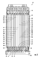
FIG. 1 is a schematic of the battery module in accordance with an exemplary embodiment; -
FIG. 2 is a cross-sectional schematic of the battery module ofFIG. 1 ; -
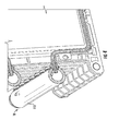
FIG. 3 is an enlarged schematic of a portion of the battery module ofFIG. 2 illustrating first and second cooling manifolds; -
FIG. 4 is an enlarged schematic of a portion of the battery module ofFIG. 3 illustrating the first cooling manifold; -
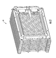
FIG. 5 is a schematic of a portion of the battery module ofFIG. 1 with first and second cooling manifolds removed; -
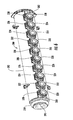
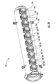
FIG. 6 is a schematic of a cooling manifold utilized in the battery module ofFIG. 1 ; -
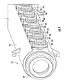
FIG. 7 is an exploded schematic of the cooling manifold ofFIG. 6 ; -
FIG. 8 is a cross-sectional schematic of the cooling manifold ofFIG. 6 taken along a longitudinal axis of the cooling manifold; -
FIG. 9 is an enlarged schematic of a portion of the cooling manifold ofFIG. 6 ; -
FIG. 10 is another enlarged schematic of a portion of the cooling manifold ofFIG. 6 ; -
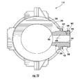
FIG. 11 is a cross-sectional schematic of the cooling manifold ofFIG. 6 ; -
FIG. 12 is a cross-sectional schematic of the cooling manifold ofFIG. 6 and a portion of a tube from a heat exchanger coupled to the cooling manifold; -
FIG. 13 is a cross-sectional schematic of the cooling manifold ofFIG. 6 and of a tube from a heat exchanger coupled to the cooling manifold; -
FIG. 14 is a schematic of a heat exchanger coupled to the cooling manifold ofFIG. 6 ; -
FIG. 15 is a schematic of a portion of a cooling manifold that utilizes split-ring shaped members on the fluid ports in accordance with another exemplary embodiment; and -
FIG. 16 is another schematic of the cooling manifold ofFIG. 6 with an end cap. - Referring to
FIGS. 1-5 , abattery module 10 for providing electrical power is provided. Thebattery module 10 includesend plates frame members heat exchangers battery cells cooling manifolds cooling manifolds - The
end plates battery module 10 and the frame members, the heat exchangers, and the battery cells are disposed between theend plates - Referring to
FIGS. 1 ,2 ,3 and14 , theheat exchangers cooling manifold 110 that flows through the heat exchangers to cool thebattery cells cooling manifold 112 is configured to receive the fluid from the heat exchangers 60-78. The heat exchangers 60-78 have an identical structure with one another. Accordingly, only the structure of theheat exchanger 60 will be described in greater detail hereinafter. Referring toFIG. 14 , theheat exchanger 60 includes atube 130 that is coupled to a peripheral portion of a rectangularshaped plate 132. Thetube 130 includestube portions tube portions plate 132. Thetube portions cooling manifolds - Referring to
FIG. 2 , thebattery cells - The
frame members frame member 40 and theend plate 20 are configured to hold thebattery cells heat exchanger 60 therebetween. Theheat exchanger 60 is disposed between thebattery cells battery cells - The
frame members battery cells heat exchanger 62 therebetween. Theheat exchanger 62 is disposed between thebattery cells battery cells - The
frame members battery cells 88, 90 and theheat exchanger 64 therebetween. Theheat exchanger 64 is disposed between thebattery cells 88, 90 to extract heat energy from thebattery cells 88, 90. - The
frame members battery cells heat exchanger 66 therebetween. Theheat exchanger 66 is disposed between thebattery cells battery cells - The
frame members battery cells heat exchanger 68 therebetween. Theheat exchanger 68 is disposed between thebattery cells battery cells - The
frame members battery cells heat exchanger 70 therebetween. Theheat exchanger 70 is disposed between thebattery cells battery cells - The
frame members battery cells heat exchanger 72 therebetween. Theheat exchanger 72 is disposed between thebattery cells battery cells - The
frame members battery cells heat exchanger 74 therebetween. Theheat exchanger 74 is disposed between thebattery cells battery cells - The
frame members battery cells heat exchanger 76 therebetween. Theheat exchanger 76 is disposed between thebattery cells battery cells - The
frame member 48 and theend plate 30 are configured to hold thebattery cells heat exchanger 78 therebetween. Theheat exchanger 78 is disposed between thebattery cells battery cells - Referring to
FIGS. 1 ,2 and6-13 , thecooling manifold 110 is configured to receive a fluid from a fluid cooling system (not shown) through an aperture in thefirst end portion 380. The fluid flows into theinterior region 390 and then through the fluid ports 220-238 into the heat exchangers 60-78. The heat exchangers 60-78 extract heat energy from the battery cells 80-107 and transfer the heat energy into the fluid flowing therethrough. Thereafter, fluid flows from the heat exchangers 60-78 and through the fluid ports of thecooling manifold 112 into thecooling manifold 112. From thecooling manifold 112, the fluid flows into the fluid cooling system (not shown) which cools the fluid. Since thecooling manifold 110 has an identical structure as thecooling manifold 112, only the structure of thecooling manifold 110 will be explained in greater detail below. - Referring to
FIGS. 6-10 and16 , thecooling manifold 110 is configured to receive a fluid from a fluid system (not shown) and to route the fluid into the heat exchangers 60-78. Thecooling manifold 110 includes atubular wall 200, mountingtabs end cap 210,fluid ports members gasket 350. - The
tubular wall 200 has afirst end portion 380 and asecond end portion 382. Thetubular wall 200 further defines aninterior region 390 that fluidly communicates with apertures in each of the fluid ports 220-238. In one exemplary embodiment, thetubular wall 200 is constructed of plastic. Of course, in alternate embodiments, thetubular wall 200 could be constructed of other materials known to those skilled in the art. - The mounting
tabs tubular wall 200 at thesecond end portion 382 of thetubular wall 200. The mounting tabs 200-205 are configured to be coupled to theend cap 210 which is disposed on thesecond end portion 382 to enclose thesecond end portion 382. In one exemplary embodiment, the mounting tabs 200-205 and theend cap 210 are constructed of plastic, and theend cap 210 is ultrasonically welded to the mounting tabs 200-205. - The fluid ports 220-238 extend outwardly from the
outer surface 392 of thetubular wall 200 and fluidly communicate with theinterior region 390 defined by thetubular wall 200. The fluid ports 220-238 are disposed linearly along theouter surface 392 and are spaced apart from one another. Because the fluid ports 220-238 have an identical structure to one another, only the structure of thefluid port 220 will be discussed in greater detail below. - Referring to
FIG. 11 , thefluid port 220 has atubular port body 450 and a ring shapedseating portion 452. Thetubular body portion 450 includes acoupling body portion 456, thecentral body portion 458, and anouter lip portion 460. Thecoupling body portion 456 extends through thetubular wall 200 of thecooling manifold 110 and is integrally attached to thetubular wall 200. Thecentral body portion 458 extends from thecoupling body portion 456 and is further coupled to theouter lip portion 460. Thetubular port body 450 further includes anouter surface 462 and anaperture 464 that extends through thetubular port body 450. In particular, theaperture 464 extends through thecoupling body portion 456, thecentral body portion 458, and theouter lip portion 460. Thecentral body portion 458 defines agroove 490 thereon. The ring shapedseating portion 452 extends outwardly from thecentral body portion 458 and extends around an outer periphery of thecentral body portion 458. In one exemplary embodiment, thetubular port body 450 and the ring shapedseating portion 452 are constructed of an elastomeric material such as a thermoplastic elastomer for example. Of course, in alternative embodiments, other elastomeric materials could be utilized to construct thetubular port body 450 and the ring shapedseating portion 452 or portion thereof. - Referring to
FIGS. 6 and7 , the ring shapedmembers fluid ports - Referring to
FIGS. 11 and12 , for purposes of simplicity, only the configuration of the ring shapedmember 320 on thefluid port 220 will be explained in greater detail below. The ring shapedmember 320 is disposed on theouter surface 462 of the tubular port body 450 a predetermined distance from theouter surface 392 of thetubular wall 200. In particular, in one exemplary embodiment, the ring shapedmember 320 is disposed on thecentral body portion 458 in thegroove 490 defined by thecentral body portion 458 and is disposed between the ring shapedseating portion 452 and theouter lip portion 460. An inner diameter of the ring shapedmember 320 is less than an uncompressed outer diameter of thetubular port body 450 of thefluid port 220. An outer diameter of the ring shapedmember 320 is greater than an outer diameter of thetubular port body 450 of thefluid port 220. The ring shapedseating portion 452 and theouter lip portion 460 assists in maintaining the position of the ring shapedmember 320 in thegroove 490. The ring shapedmember 320 is constructed of a rigid material that prevents thetubular port body 450 from expanding radially outwardly in a region of thetubular port body 450 surrounded by the ring shapedmember 320 when a tube from the heat exchanger is inserted into thetubular port body 450. As a result, the region of thetubular port body 450 surrounded by the ring shapedmember 320 provides an improved fluid seal between thetubular port body 450 and the heat exchanger tube. In one exemplary embodiment, the rigid material utilized to construct the ring shapedmember 320 is steel. Of course, in alternate embodiments, other materials known to those skilled in the art could be utilized to construct the ring shapedmember 320. - Referring again to
FIGS. 6-9 , theseal 350 is disposed around thefirst end portion 380 of thetubular wall 200. Theseal 350 is configured to provide a fluid seal between thefirst end portion 380 and a fluid system operably coupled to thefirst end portion 380 that supplies fluid through thefirst end portion 380 into theinterior region 380. - Referring to
FIG. 15 , a portion of acooling manifold 500 having afluid port 502 extending therefrom is illustrated. Thefluid port 502 has a split-ring shapedmember 510 extending around the periphery of thefluid port 502 that prevents thefluid port 502 from expanding radially outwardly in a region of thefluid port 502 surrounded by the split-ring shapedmember 510 when a tube from a respective heat exchanger is inserted into thefluid port 502. The split-ring shapedmember 510 is constructed from a substantially rigid material. In one exemplary embodiment, the split-ring shapedmember 510 is constructed of steel. Of course, in alternative embodiments, other materials known to those skilled in the art could be utilized to construct the split-ring shapedmember 510. - The structure of the
cooling manifold 500 is substantially similar to the structure of thecooling manifold 110 except that split-ring shaped members are coupled to the fluid ports, instead of the ring shaped members utilized on thecooling manifold 110. - The battery modules described herein provide a substantial advantage over other battery modules. In particular, the battery modules utilize a cooling manifold with ring shaped members or split-ring shaped members that surround portions of the fluid ports to prevent the fluid ports from expanding radially outwardly in a region of the fluid ports surrounded by the ring shaped members or the split-ring shaped members when tubes from the heat exchanger is inserted into the fluid ports. As a result, an improved fluid seal between each fluid port and each heat exchanger tube is obtained.
- While the claimed invention has been described in detail in connection with only a limited number of embodiments, it should be readily understood that the invention is not limited to such disclosed embodiments. Rather, the claimed invention can be modified to incorporate any number of variations, alterations, substitutions or equivalent arrangements not heretofore described, but which are commensurate with the spirit and scope of the invention. Additionally, while various embodiments of the claimed invention have been described, it is to be understood that aspects of the invention may include only some of the described embodiments. Accordingly, the claimed invention is not to be seen as limited by the foregoing description.
Claims (14)
- A battery module, comprising:a battery cell;a heat exchanger disposed adjacent to the battery cell;a cooling manifold having a tubular wall, a first fluid port, and a ring shaped member;the tubular wall defining an interior region and having first and second end portions;the first fluid port extending outwardly from an outer surface of the tubular wall and fluidly communicating with the interior region, the first fluid port extending through the tubular wall and being integrally attached to the tubular wall;the ring shaped member being disposed on an outer surface of the first fluid port a predetermined distance from the outer surface of the tubular wall, the ring shaped member being constructed of a rigid material that prevents the first fluid port from expanding radially outwardly when a tube from the heat exchanger is inserted into the first fluid port.
- The battery module of claim 1, wherein an inner diameter of the ring shaped member is less than an uncompressed outer diameter of a tubular port body of the first fluid port.
- The battery module of claim 1, wherein the first fluid port is constructed of an elastomeric material and the ring shaped member is constructed of the rigid material.
- The battery module of claim 3, wherein the elastomeric material comprises a thermoplastic elastomer.
- The battery module of claim 4, wherein the rigid material comprises steel.
- The battery module of claim 1, wherein an outer diameter of the ring shaped member is greater than an outer diameter of a tubular port body of the first fluid port.
- The battery module of claim 1, further comprising a plurality of additional fluid ports extending outwardly from the outer surface of the tubular wall and fluidly communicating with the interior region, the plurality of additional fluid ports being disposed linearly along the outer surface and spaced apart from one another, the plurality of additional fluid ports having a structure identical to a structure of the first fluid port.
- A battery module, comprising:a battery cell;a heat exchanger disposed adjacent to the battery cell;a cooling manifold having a tubular wall, a first fluid port, and a split-ring shaped member;the tubular wall defining an interior region and having first and second end portions;the first fluid port extending outwardly from an outer surface of the tubular wall and fluidly communicating with the interior region, the first fluid port extending through the tubular wall and being integrally attached to the tubular wall;the split-ring shaped member being disposed on an outer surface of the first fluid port a predetermined distance from the outer surface of the tubular wall, the split-ring shaped member being constructed of a rigid material that prevents the first fluid port from expanding radially outwardly when a tube from the heat exchanger is inserted into the first fluid port.
- The battery module of claim 8, wherein an inner diameter of the split-ring shaped member is less than an uncompressed outer diameter of a tubular port body of the first fluid port.
- The battery module of claim 8, wherein the first fluid port is constructed of an elastomeric material and the split-ring shaped member is constructed of the rigid material.
- The battery module of claim 10, wherein the elastomeric material comprises a thermoplastic elastomer.
- The battery module of claim 11, wherein the rigid material comprises steel.
- The battery module of claim 8, wherein an outer diameter of the split-ring shaped member is greater than an outer diameter of a tubular port body of the first fluid port.
- The battery module of claim 8, further comprising a plurality of additional fluid ports extending outwardly from the outer surface of the tubular wall and fluidly communicating with the interior region, the plurality of additional fluid ports being disposed linearly along the outer surface and spaced apart from one another, the plurality of additional fluid ports having a structure identical to a structure of the first fluid port.
Applications Claiming Priority (2)
| Application Number | Priority Date | Filing Date | Title |
|---|---|---|---|
| US13/587,102 US8974934B2 (en) | 2012-08-16 | 2012-08-16 | Battery module |
| PCT/KR2013/007268 WO2014027816A1 (en) | 2012-08-16 | 2013-08-13 | Battery module |
Publications (2)
| Publication Number | Publication Date |
|---|---|
| EP2887423A1 true EP2887423A1 (en) | 2015-06-24 |
| EP2887423A4 EP2887423A4 (en) | 2015-08-19 |
Family
ID=50100247
Family Applications (1)
| Application Number | Title | Priority Date | Filing Date |
|---|---|---|---|
| EP13879477.1A Withdrawn EP2887423A4 (en) | 2012-08-16 | 2013-08-13 | Battery module |
Country Status (6)
| Country | Link |
|---|---|
| US (1) | US8974934B2 (en) |
| EP (1) | EP2887423A4 (en) |
| JP (1) | JP2015528997A (en) |
| KR (1) | KR101636385B1 (en) |
| CN (1) | CN104756279B (en) |
| WO (1) | WO2014027816A1 (en) |
Cited By (1)
| Publication number | Priority date | Publication date | Assignee | Title |
|---|---|---|---|---|
| DE102020106616B3 (en) | 2020-03-11 | 2021-09-16 | Bayerische Motoren Werke Aktiengesellschaft | Cooling device, battery and motor vehicle |
Families Citing this family (17)
| Publication number | Priority date | Publication date | Assignee | Title |
|---|---|---|---|---|
| FR3020722A1 (en) * | 2014-04-30 | 2015-11-06 | Valeo Systemes Thermiques | DEVICE FOR SUPPORTING A TUBE, IN PARTICULAR A TUBE OF A HEAT EXCHANGER INTENDED TO COME IN CONTACT WITH A BATTERY OF A MOTOR VEHICLE |
| DE102014106941A1 (en) * | 2014-05-16 | 2015-11-19 | Valeo Klimasysteme Gmbh | Cooling device for a battery pack |
| KR101833526B1 (en) * | 2014-05-29 | 2018-02-28 | 주식회사 엘지화학 | Battery Module Having Water-Cooled Type Cooling Structure |
| KR102378426B1 (en) * | 2014-07-28 | 2022-03-24 | 삼성에스디아이 주식회사 | Battery module |
| US9941557B2 (en) * | 2015-02-24 | 2018-04-10 | GM Global Technology Operations LLC | Battery system cooling systems and methods |
| US11480398B2 (en) * | 2015-05-22 | 2022-10-25 | The Johns Hopkins University | Combining complex flow manifold with three dimensional woven lattices as a thermal management unit |
| DE102015214662A1 (en) * | 2015-07-31 | 2017-02-02 | Volkswagen Aktiengesellschaft | Traction battery with battery cell modules |
| KR102295371B1 (en) * | 2016-10-13 | 2021-08-31 | 삼성에스디아이 주식회사 | Battery module |
| KR102308632B1 (en) | 2016-10-13 | 2021-10-05 | 삼성에스디아이 주식회사 | Battery module |
| KR102308630B1 (en) * | 2016-10-17 | 2021-10-05 | 삼성에스디아이 주식회사 | Battery module |
| DE102017104710A1 (en) * | 2017-03-07 | 2018-09-13 | Dr. Ing. H.C. F. Porsche Aktiengesellschaft | Battery module for use with a high-voltage energy storage |
| BR112020005831A2 (en) * | 2017-10-06 | 2020-09-24 | Norma U.S. Holding Llc | thermal battery management tubing segment and assembly thereof |
| EP3553876B1 (en) * | 2018-04-09 | 2020-07-22 | Samsung SDI Co., Ltd. | Coolant distributor |
| FR3080911B1 (en) * | 2018-05-02 | 2022-01-21 | Coutier Moulage Gen Ind | FLUID DISTRIBUTOR-COLLECTOR RAMP |
| CN208368689U (en) * | 2018-07-17 | 2019-01-11 | 宁德时代新能源科技股份有限公司 | Battery cooling component |
| DE102019214497A1 (en) * | 2019-09-23 | 2021-03-25 | Mahle International Gmbh | Pipe body arrangement for a temperature control device, temperature control device and electrical device |
| CN113451676B (en) * | 2020-03-11 | 2025-12-30 | 奥动新能源股份有限公司 | Battery boxes and electric vehicles |
Family Cites Families (53)
| Publication number | Priority date | Publication date | Assignee | Title |
|---|---|---|---|---|
| US1806364A (en) | 1929-09-25 | 1931-05-19 | Thomas S Newman | Closure cap for collapsible and other containers |
| US2814404A (en) | 1953-12-02 | 1957-11-26 | Bryant W Griffin | Closure for beaded containers |
| US3394836A (en) | 1966-01-28 | 1968-07-30 | George L Fowler | Fill tube cap |
| US3588149A (en) | 1969-08-13 | 1971-06-28 | Amp Inc | Vacuum or pressure coupling devices |
| US3750744A (en) * | 1972-05-30 | 1973-08-07 | S Bouras | Cooling radiator |
| US4009720A (en) | 1975-08-14 | 1977-03-01 | Shiley Laboratories, Inc. | Wedge seal for a tracheotomy tube |
| DE3010425A1 (en) * | 1980-03-19 | 1981-09-24 | Rasmussen Gmbh, 6457 Maintal | DEVICE FOR FASTENING A HOSE ON A PIPE |
| US4482174A (en) * | 1980-09-15 | 1984-11-13 | Lokring | Apparatus and method for making a tube connection |
| JPS5886979U (en) * | 1981-12-08 | 1983-06-13 | 横河電機株式会社 | Tube connection mechanism |
| US4706737A (en) | 1986-11-20 | 1987-11-17 | International Fuel Cells Corporation | Fuel cell coolant inlet manifold and system |
| DE8901826U1 (en) | 1988-11-23 | 1989-04-06 | Reutter Metallwarenfabrik GmbH, 71336 Waiblingen | Radiator nozzle with cover |
| US5123677A (en) | 1990-05-31 | 1992-06-23 | Swagelok-Quick Connect Co. | All plastic quick-connect coupling |
| FR2665507B1 (en) | 1990-07-31 | 1992-11-27 | Hutchinson Sa | DEVICE FOR THE QUICK ASSEMBLY OF A HOSE TO A HEAT EXCHANGER OF A MOTOR VEHICLE. |
| JP3451142B2 (en) * | 1994-11-18 | 2003-09-29 | 本田技研工業株式会社 | Battery assembly with temperature control mechanism |
| US5921467A (en) * | 1996-08-05 | 1999-07-13 | Larson; David J. | Forced air helmet heater and defroster system for sport and utility vehicles |
| US5873610A (en) | 1996-12-19 | 1999-02-23 | Itt Automotive, Inc. | Female connector member for large tolerance male member endforms |
| US5882047A (en) | 1996-12-20 | 1999-03-16 | Itt Automotive, Inc. | Quick connector fluid coupling |
| US6371319B2 (en) | 1997-09-22 | 2002-04-16 | Abbott Laboratories | Closure system for containers |
| EP0916540A3 (en) | 1997-11-12 | 2000-04-12 | Mannesmann VDO Aktiengesellschaft | Fuel feed device with pipe connector |
| US6102064A (en) | 1998-09-10 | 2000-08-15 | Robinson; Robert | Theft resistant valve cap |
| US6481759B1 (en) | 1999-03-31 | 2002-11-19 | Tokai Rubber Industries, Ltd. | Connecting structure |
| JP2001032985A (en) | 1999-07-21 | 2001-02-06 | Tokyo Gas Co Ltd | Piping fitting |
| US6257417B1 (en) | 1999-10-01 | 2001-07-10 | James A. Szumera | Automotive oil filter housing |
| FR2801569B1 (en) | 1999-11-29 | 2002-04-26 | Valois Sa | SAFETY CAP |
| JP4543464B2 (en) | 1999-12-09 | 2010-09-15 | トヨタ自動車株式会社 | Battery pack |
| FR2803084B1 (en) | 1999-12-27 | 2002-04-19 | Itt Mfg Entpr S Inc | ELECTRIC SWITCH WITH TACTILE EFFECT FIXED BY ELASTIC SOCKET ON A CIRCUIT PLATE |
| US6295980B1 (en) | 2000-01-12 | 2001-10-02 | Pacfab, Inc. | Composite polymer manifold for water heating unit |
| JP2001272195A (en) * | 2000-03-27 | 2001-10-05 | Calsonic Kansei Corp | Radiator incorporating oil cooler and method of manufacturing the same |
| US6688654B2 (en) | 2000-12-08 | 2004-02-10 | Newfrey Llc | One piece quick connector |
| DE10130369A1 (en) | 2001-06-23 | 2003-01-02 | Behr Gmbh & Co | Device for cooling a vehicle device, in particular battery or fuel cell |
| FR2829219B1 (en) | 2001-09-04 | 2004-12-17 | Hutchinson | PRE-ASSEMBLED SEALING FITTING |
| EP1479125A2 (en) | 2002-02-20 | 2004-11-24 | Acumentrics Corporation | Fuel cell stacking and sealing |
| JP2004006089A (en) | 2002-05-31 | 2004-01-08 | Toyota Motor Corp | Battery system |
| JP4366100B2 (en) | 2003-03-24 | 2009-11-18 | パナソニックEvエナジー株式会社 | Battery pack |
| US20050082828A1 (en) | 2003-09-12 | 2005-04-21 | Wicks Jeffrey C. | Releasable connection assembly for joining tubing sections |
| JP4669242B2 (en) | 2004-07-14 | 2011-04-13 | 本田技研工業株式会社 | Piping member for fuel cell and manufacturing method thereof |
| JP2006210245A (en) | 2005-01-31 | 2006-08-10 | Toyota Motor Corp | Battery module cooling device |
| US20070087266A1 (en) | 2005-10-18 | 2007-04-19 | Debbi Bourke | Modular battery system |
| DE102007006588B4 (en) | 2007-02-09 | 2014-04-17 | Modine Manufacturing Co. | Quick Couplings |
| KR100820519B1 (en) * | 2007-03-23 | 2008-04-08 | 지에스칼텍스 주식회사 | Fuel Cell Stack Chiller |
| US7846573B2 (en) * | 2007-06-01 | 2010-12-07 | Cobasys, Llc | Coolant manifold |
| US20080311468A1 (en) * | 2007-06-18 | 2008-12-18 | Weston Arthur Hermann | Optimized cooling tube geometry for intimate thermal contact with cells |
| JP5111212B2 (en) * | 2008-04-12 | 2013-01-09 | 未来工業株式会社 | Water pipe connector |
| US9140501B2 (en) * | 2008-06-30 | 2015-09-22 | Lg Chem, Ltd. | Battery module having a rubber cooling manifold |
| US8067111B2 (en) * | 2008-06-30 | 2011-11-29 | Lg Chem, Ltd. | Battery module having battery cell assembly with heat exchanger |
| US7883793B2 (en) | 2008-06-30 | 2011-02-08 | Lg Chem, Ltd. | Battery module having battery cell assemblies with alignment-coupling features |
| US8426050B2 (en) * | 2008-06-30 | 2013-04-23 | Lg Chem, Ltd. | Battery module having cooling manifold and method for cooling battery module |
| US8327887B2 (en) * | 2008-10-27 | 2012-12-11 | All-American Hose Llc | Hose |
| CN102257652B (en) * | 2008-11-12 | 2014-04-02 | 江森自控帅福得先进能源动力系统有限责任公司 | Battery system with heat exchanger |
| US8469404B2 (en) | 2010-08-23 | 2013-06-25 | Lg Chem, Ltd. | Connecting assembly |
| US8353315B2 (en) | 2010-08-23 | 2013-01-15 | Lg Chem, Ltd. | End cap |
| US8920956B2 (en) | 2010-08-23 | 2014-12-30 | Lg Chem, Ltd. | Battery system and manifold assembly having a manifold member and a connecting fitting |
| DE102010049015B4 (en) * | 2010-10-21 | 2013-12-05 | Johnson Controls Hybrid And Recycling Gmbh | Coolant manifold hose and battery assembly |
-
2012
- 2012-08-16 US US13/587,102 patent/US8974934B2/en active Active
-
2013
- 2013-08-13 KR KR1020157004155A patent/KR101636385B1/en active Active
- 2013-08-13 EP EP13879477.1A patent/EP2887423A4/en not_active Withdrawn
- 2013-08-13 JP JP2015526473A patent/JP2015528997A/en active Pending
- 2013-08-13 WO PCT/KR2013/007268 patent/WO2014027816A1/en not_active Ceased
- 2013-08-13 CN CN201380042980.5A patent/CN104756279B/en active Active
Cited By (1)
| Publication number | Priority date | Publication date | Assignee | Title |
|---|---|---|---|---|
| DE102020106616B3 (en) | 2020-03-11 | 2021-09-16 | Bayerische Motoren Werke Aktiengesellschaft | Cooling device, battery and motor vehicle |
Also Published As
| Publication number | Publication date |
|---|---|
| JP2015528997A (en) | 2015-10-01 |
| CN104756279A (en) | 2015-07-01 |
| WO2014027816A1 (en) | 2014-02-20 |
| CN104756279B (en) | 2017-05-03 |
| KR101636385B1 (en) | 2016-07-05 |
| US20140050952A1 (en) | 2014-02-20 |
| KR20150043337A (en) | 2015-04-22 |
| EP2887423A4 (en) | 2015-08-19 |
| US8974934B2 (en) | 2015-03-10 |
Similar Documents
| Publication | Publication Date | Title |
|---|---|---|
| EP2887423A1 (en) | Battery module | |
| US9444124B2 (en) | Battery cell assembly and method for coupling a cooling fin to first and second cooling manifolds | |
| US9806381B2 (en) | Serpentine cooling element for battery assembly | |
| KR102884018B1 (en) | Refrigerant distributor | |
| US8920956B2 (en) | Battery system and manifold assembly having a manifold member and a connecting fitting | |
| US9140501B2 (en) | Battery module having a rubber cooling manifold | |
| EP2610947B1 (en) | Battery system including a manifold member and a connection fitting, and manifold assembly | |
| CN104737327B (en) | Battery module and method for manufacturing battery module | |
| EP2610941B1 (en) | Connecting assembly | |
| EP3182503A1 (en) | Battery pack | |
| US8758922B2 (en) | Battery system and manifold assembly with two manifold members removably coupled together | |
| US10476045B2 (en) | Extruded battery case | |
| EP2562848A2 (en) | Battery cell assembly | |
| US20200176838A1 (en) | Battery module | |
| US8353315B2 (en) | End cap | |
| KR20180068993A (en) | Temperature control system for battery systems | |
| US20170187084A1 (en) | Unit cell pack | |
| JP6500988B2 (en) | Power supply | |
| US10601086B2 (en) | Cooling system for cooling electrochemical cells of a battery system | |
| JP2017515086A (en) | Automotive heat exchanger header | |
| KR102066701B1 (en) | Battery pack case improved in coolong performance | |
| KR20150128360A (en) | Cooling system for battery module | |
| CN111276652A (en) | battery module | |
| US9991571B2 (en) | Battery module with flanges in fluidic communication | |
| US10249920B2 (en) | Battery cell assembly |
Legal Events
| Date | Code | Title | Description |
|---|---|---|---|
| PUAI | Public reference made under article 153(3) epc to a published international application that has entered the european phase |
Free format text: ORIGINAL CODE: 0009012 |
|
| 17P | Request for examination filed |
Effective date: 20150210 |
|
| AK | Designated contracting states |
Kind code of ref document: A1 Designated state(s): AL AT BE BG CH CY CZ DE DK EE ES FI FR GB GR HR HU IE IS IT LI LT LU LV MC MK MT NL NO PL PT RO RS SE SI SK SM TR |
|
| AX | Request for extension of the european patent |
Extension state: BA ME |
|
| RA4 | Supplementary search report drawn up and despatched (corrected) |
Effective date: 20150721 |
|
| RIC1 | Information provided on ipc code assigned before grant |
Ipc: F28F 1/00 20060101ALI20150715BHEP Ipc: H01M 2/10 20060101AFI20150715BHEP Ipc: H01M 10/6567 20140101ALI20150715BHEP Ipc: F28F 9/14 20060101ALI20150715BHEP |
|
| DAX | Request for extension of the european patent (deleted) | ||
| 17Q | First examination report despatched |
Effective date: 20160512 |
|
| 18W | Application withdrawn |
Effective date: 20170427 |
|
| STAA | Information on the status of an ep patent application or granted ep patent |
Free format text: STATUS: THE APPLICATION HAS BEEN WITHDRAWN |