EP2887080A1 - Power supply apparatus - Google Patents
Power supply apparatus Download PDFInfo
- Publication number
- EP2887080A1 EP2887080A1 EP13840155.9A EP13840155A EP2887080A1 EP 2887080 A1 EP2887080 A1 EP 2887080A1 EP 13840155 A EP13840155 A EP 13840155A EP 2887080 A1 EP2887080 A1 EP 2887080A1
- Authority
- EP
- European Patent Office
- Prior art keywords
- ground fault
- switch
- sensing means
- electrode
- power supply
- Prior art date
- Legal status (The legal status is an assumption and is not a legal conclusion. Google has not performed a legal analysis and makes no representation as to the accuracy of the status listed.)
- Granted
Links
Images




Classifications
-
- G—PHYSICS
- G01—MEASURING; TESTING
- G01R—MEASURING ELECTRIC VARIABLES; MEASURING MAGNETIC VARIABLES
- G01R31/00—Arrangements for testing electric properties; Arrangements for locating electric faults; Arrangements for electrical testing characterised by what is being tested not provided for elsewhere
- G01R31/40—Testing power supplies
-
- G—PHYSICS
- G01—MEASURING; TESTING
- G01R—MEASURING ELECTRIC VARIABLES; MEASURING MAGNETIC VARIABLES
- G01R31/00—Arrangements for testing electric properties; Arrangements for locating electric faults; Arrangements for electrical testing characterised by what is being tested not provided for elsewhere
- G01R31/50—Testing of electric apparatus, lines, cables or components for short-circuits, continuity, leakage current or incorrect line connections
-
- G—PHYSICS
- G01—MEASURING; TESTING
- G01R—MEASURING ELECTRIC VARIABLES; MEASURING MAGNETIC VARIABLES
- G01R31/00—Arrangements for testing electric properties; Arrangements for locating electric faults; Arrangements for electrical testing characterised by what is being tested not provided for elsewhere
- G01R31/36—Arrangements for testing, measuring or monitoring the electrical condition of accumulators or electric batteries, e.g. capacity or state of charge [SoC]
-
- G—PHYSICS
- G01—MEASURING; TESTING
- G01R—MEASURING ELECTRIC VARIABLES; MEASURING MAGNETIC VARIABLES
- G01R31/00—Arrangements for testing electric properties; Arrangements for locating electric faults; Arrangements for electrical testing characterised by what is being tested not provided for elsewhere
- G01R31/36—Arrangements for testing, measuring or monitoring the electrical condition of accumulators or electric batteries, e.g. capacity or state of charge [SoC]
- G01R31/382—Arrangements for monitoring battery or accumulator variables, e.g. SoC
-
- G—PHYSICS
- G01—MEASURING; TESTING
- G01R—MEASURING ELECTRIC VARIABLES; MEASURING MAGNETIC VARIABLES
- G01R31/00—Arrangements for testing electric properties; Arrangements for locating electric faults; Arrangements for electrical testing characterised by what is being tested not provided for elsewhere
- G01R31/50—Testing of electric apparatus, lines, cables or components for short-circuits, continuity, leakage current or incorrect line connections
- G01R31/52—Testing for short-circuits, leakage current or ground faults
-
- H—ELECTRICITY
- H02—GENERATION; CONVERSION OR DISTRIBUTION OF ELECTRIC POWER
- H02S—GENERATION OF ELECTRIC POWER BY CONVERSION OF INFRARED RADIATION, VISIBLE LIGHT OR ULTRAVIOLET LIGHT, e.g. USING PHOTOVOLTAIC [PV] MODULES
- H02S50/00—Monitoring or testing of PV systems, e.g. load balancing or fault identification
- H02S50/10—Testing of PV devices, e.g. of PV modules or single PV cells
-
- Y—GENERAL TAGGING OF NEW TECHNOLOGICAL DEVELOPMENTS; GENERAL TAGGING OF CROSS-SECTIONAL TECHNOLOGIES SPANNING OVER SEVERAL SECTIONS OF THE IPC; TECHNICAL SUBJECTS COVERED BY FORMER USPC CROSS-REFERENCE ART COLLECTIONS [XRACs] AND DIGESTS
- Y02—TECHNOLOGIES OR APPLICATIONS FOR MITIGATION OR ADAPTATION AGAINST CLIMATE CHANGE
- Y02E—REDUCTION OF GREENHOUSE GAS [GHG] EMISSIONS, RELATED TO ENERGY GENERATION, TRANSMISSION OR DISTRIBUTION
- Y02E10/00—Energy generation through renewable energy sources
- Y02E10/50—Photovoltaic [PV] energy
Definitions
- the present invention relates to a power supply device.
- a ground fault detection device for detecting ground faults in a direct-current power source grid comprising a battery group in which a detection resistor and a coupling capacitor for direct-current cutoff are connected between a pulse signal generating means and a ground fault detection terminal connected to a direct-current negative electrode feed line, and a reduction in insulation resistance during a ground fault is sensed from the difference between a reference voltage and the detected voltage of a pulse signal occurring at a point of connection of the detection resistor and the coupling capacitor (Patent Document 1).
- Patent Document 1 Japanese Laid-Open Patent Application No. 2004-138434
- the direct-current power source grid described above is connected to alternating-current grid electric power via an inverter, and a direct-current power source is charged by the alternating-current grid electric power, the alternating-current grid electric power is grounded.
- the conventional ground fault detection device described above therefore has the drawback of being incapable of sensing a reduction in insulation resistance during a ground fault.
- An object of the present invention is to provide a power supply device provided with a grounded alternating-current power source and a secondary cell connected to the alternating-current power source, the power supply device being capable of detecting a ground fault in the secondary cell.
- a first switch for selectively connecting or cutting off a secondary cell and an alternating-current power source is connected between the secondary cell and the alternating-current power source, a ground fault sensing means for sensing a ground fault in the secondary cell is connected closer to the secondary cell than the first switch, and a ground fault in the secondary cell is sensed by the ground fault sensing means in a state in which the first switch is off.
- a grounding portion of the alternating-current power source and a circuit portion for sensing of a ground fault in the secondary cell by the ground fault sensing means are cut off by the turning off of the first switch.
- a ground fault in the secondary cell can therefore be sensed without affecting the grounding of the alternating-current power source.
- FIG. 1 is a circuit diagram illustrating the power supply system of the power supply device according to an embodiment of the present invention.
- the power supply device of the present example is applied to a household or commercial power supply system which uses an alternating-current power source as one current source.
- the power supply system including the power supply device of the present example is provided with an alternating-current power source 10, an inverter 20, a battery (secondary cell) 30, a smoothing capacitor 40, a relay switch 50 (first switch), and a ground fault sensing circuit 60.
- the alternating-current power source 10 is an electric power source for supplying electric power to a load not illustrated in the drawing, and is also an electric power source for supplying charging electric power to the battery 30 via the inverter 20.
- the alternating-current power source 10 includes a transformer, and is grounded by connecting a neutral point of the secondary side of the transformer to ground.
- the transformer is a common transformer provided to a household or facility to transform alternating-current electric power supplied from a power company for output, for example.
- the inverter 20 is an AC/DC conversion circuit in which a plurality of switching elements is connected in bridged fashion, and is a conversion circuit for converting alternating-current electric power supplied from the alternating-current power source 10 into direct-current electric power and supplying the direct-current electric power to the battery 30.
- the inverter 20 converts direct-current electric power outputted from the battery 30 into alternating-current electric power and supplies electric power to a load 110.
- the inverter 20 is connected to a pair of power supply lines connected to the alternating-current power source 10 and is connected between the alternating-current power source 10 and the battery 30.
- the battery 30 is a storage cell in which a plurality of lithium-ion cells or other secondary cells is connected.
- the battery 30 is a cell for storing electric power to be supplied to a load not illustrated in the drawing.
- electric power is controlled so that the battery 30 is charged by electric power from the alternating-current power source 10 during late-night hours in which electric utility rates are inexpensive, and the electric power saved in the battery 30 is supplied to a load during daytime hours, for example.
- the smoothing capacitor 40 is a capacitor for rectifying the electric power supplied to the battery 30 from the inverter 20, and is connected between the positive-electrode side and negative-electrode side of the pair of power supply lines, and connected between the inverter 20 and the relay switch 50.
- the relay switch 50 is a switch for providing conduction and cutoff between the battery 30 and the alternating-current power source 10, and is connected between the inverter 20 and the battery 30. When the relay switch 50 is off, electric power from the battery 30 is not supplied to the inverter 20, and electric power from the inverter 20 is not supplied to the battery 30.
- the ground fault sensing circuit 60 is a circuit for sensing a ground fault in the battery 30, and is connected on the battery 30 side of the relay switch 50.
- the ground fault sensing circuit 60 is connected to an electric power line for connecting a negative electrode of the battery 30 and a junction on the negative-electrode side of the relay switch 50.
- the ground fault sensing circuit 60 is connected between the battery 30 and the relay switch 50, and when the relay switch 50 is off, the ground fault sensing circuit 60 therefore becomes able to sense a ground fault (i.e., a decrease in insulation resistance) by detecting the insulation resistance of the battery 30.
- the ground fault sensing circuit 60 has capacitors 61, 65, resistors 62, 64, a pulse transmitter 63, and a comparator 67.
- One end of the capacitor 61 is connected to the battery 30 (to an electric power line connected to an electrode terminal of the battery 30), and the other end is connected to the pulse transmitter 63 via the resistor 62.
- the pulse transmitter 63 is connected to the power supply line via a series circuit of the capacitor 61 and the resistor 62.
- a low-pass filter comprising the series circuit of the resistor 64 and the capacitor 65 is connected to the connection point (measurement point) between the capacitor 61 and the resistor 62.
- the input side of the comparator 67 is connected to a reference voltage 66 and the connection point between the resistor 64 and the capacitor 65, and the output side of the comparator 67 is connected to a controller described hereinafter.
- a pulse which is a voltage signal having a predetermined amplitude is outputted from the pulse transmitter 63 and inputted to the battery 30 (to an electric power line connected to an electrode terminal of the battery 30) via the capacitor 61.
- a voltage variation at the other-end side of the capacitor 61, i.e., on the side of the point of connection to the resistor 62 (at the measurement point), in accordance with the insulation resistance of the battery 30 is manifested as an amplitude variation in the input voltage inputted to a comparator 97. Therefore, by comparing the amplitude voltage and the reference voltage, the ground fault sensing circuit 60 determines whether the insulation resistance of the battery 30 has decreased.
- the reference voltage is a voltage threshold value set in advance that corresponds to the insulation resistance for sensing a ground fault in the battery 30.
- the amplitude (amplitude voltage) of the input voltage inputted to the comparator 97 corresponds to the insulation voltage, and a decrease in the insulation resistance of the battery 30 (a ground fault) is therefore detected by comparing the amplitude voltage with the reference voltage.
- the ground fault sensing circuit 60 can also be considered to detect the insulation resistance (i.e., the amplitude voltage) and compare the detected insulation resistance with an insulation resistance that serves as a reference for sensing a ground fault (i.e., a reference voltage) to sense the occurrence of a ground fault.
- the ground fault sensing circuit 60 thereby senses a ground fault in the battery 30 by comparing the reference voltage and the amplitude voltage for the input pulse of the pulse transmitter 63.
- the load 110 is an electrical equipment load provided to a household or facility that is driven by alternating-current electric power from the alternating-current power source 10 or alternating-current electric power outputted from the inverter 20.
- FIG. 2 is a block diagram illustrating the electric power grid of the power supply system of FIG. 1 .
- thick lines indicate electric power lines (power supply lines) and arrows indicate signal lines.
- the alternating-current power source 10, the inverter 20, the relay switch 50, the load 110, and the battery 30 are connected by electric power lines.
- a controller 100 controls the alternating-current power source 10, the inverter 20, the battery 30, the relay switch 50, and the ground fault sensing circuit 60, and is connected by signal lines.
- the controller 100 switches between a normal control mode and a ground fault sensing mode for sensing a ground fault in the battery 30, and controls the relay switch 50 and other components.
- the normal control mode will first be described.
- the controller 100 turns on the relay switch 50 and creates a state in which electric power from the battery 30 is supplied to the load 110 (via the inverter 20), electric power from the alternating-current power source 10 is supplied to the battery 30 (via the inverter 20), and it is possible to charge the battery 30.
- the controller 100 controls the alternating-current power source 10, the inverter 20, and the battery 30 in accordance with the demand electric power, a time block, or another factor that corresponds to the usage status of the load. For example, in daytime or other time blocks in which electric utility rates are high, the controller 100 supplies electric power from the battery 30 to the load 110.
- the controller 100 supplies electric power from the alternating-current power source 10 to the load 110 in addition to the electric power of the battery 30.
- the controller 100 charges the battery 30 while supplying electric power from the alternating-current power source 10 to the load 110.
- the controller 100 manages the charging state of the battery 30 and controls the charging electric power supplied from the inverter 20 to the battery 30 so that the battery 30 is not overcharged.
- the controller 100 thereby manages electric power in the power supply system of the present example.
- the ground fault sensing mode will next be described.
- the relay switch 50 when a pulse is issued from the pulse transmitter 63, voltages are compared by the comparator 67, and the insulation resistance of the battery 30 is thereby detected in order for the ground fault sensing means 60 to sense a ground fault in the battery 30, grounding of the alternating-current power source 10 causes the amplitude voltage inputted to the comparator 67 to fall below the voltage threshold value.
- the insulation resistance of the battery 30 therefore decreases even when there is no ground fault in the battery 30, and it is possible for a ground fault in the battery 30 to be erroneously sensed. Control is therefore performed in the present example so that the relay switch 50 is placed in the off state prior to ground fault sensing by the ground fault sensing circuit 60.
- the controller 100 When the ground fault sensing mode is to be executed, the controller 100 first confirms the on or off state of the relay switch 50. When the relay switch 50 is off, the controller 100 activates the ground fault sensing circuit 60 and senses a ground fault in the battery 30 by measuring the insulation resistance of the battery 30.
- the controller 100 detects the electric current flowing through the relay switch 50 and determines whether the detected electric current is lower than a predetermined electric current threshold value.
- the electric current threshold value is set in advance and is an electric current having the threshold value necessary for turning off the relay switch 50.
- the detected electric current may be detected by connecting an electric current sensor to the power supply line to which the relay switch 50 is connected.
- the controller 100 may detect the electric current flowing to the relay switch 50 from the charging/discharging electric power of the battery 30.
- the relay switch 50 When the detected electric current in the relay switch 50 is lower than the electric current threshold value (e.g., when the detected electric current is substantially zero), the relay switch 50 is turned off, and even when the supply of electric power from the battery 30 to the load 110 is cut off, because the decrease in electric power supplied to the load 110 due to the cutoff is small, the load 110 can be driven by the electric power from the alternating-current power source 10.
- the battery 30 When the battery 30 is being charged, the battery 30 may be charged after ground fault sensing is completed. Consequently, when the detected electric current in the relay switch 50 is lower than the electric current threshold value, the controller 100 turns off the relay switch 50, activates the ground fault sensing circuit 60, and performs ground fault detection in the battery 30.
- the controller 100 detects the electric current in the relay switch 50 while leaving the relay switch 50 in the on state. At the instant that the detected electric current in the relay switch 50 becomes lower than the electric current threshold value, the controller 100 turns off the relay switch and senses ground faults in the battery 30.
- the controller 100 restricts charging and discharging of the battery 30 by maintaining the relay switch 50 in the off state while notifying a user that a ground fault has occurred.
- FIG. 3 is a flowchart illustrating the procedure of control by the controller 100.
- the controller 100 performs the control process illustrated in FIG. 3 when executing the ground fault sensing mode.
- step S1 the controller 100 confirms whether the relay switch 50 (first switch) is off. When the relay switch 50 is off, the process proceeds to step S5.
- the controller 100 detects the electric current in the relay switch 50 (step S2). In step S3, the controller 100 compares the detected electric current in the relay switch 50 and the electric current threshold value. When the detected electric current in the relay switch 50 is equal to or greater than the electric current threshold value, the process returns to step S2, and the electric current in the relay switch 50 is again detected.
- the controller 100 turns off the relay switch 50 (step S4).
- step S5 the controller 100 activates the ground fault sensing circuit 60.
- step S6 the ground fault sensing circuit 60 measures the insulation resistance of the battery 30 by measuring the response voltage for the pulse of the pulse transmitter 63.
- step S7 the ground fault sensing circuit 60 detects whether the insulation resistance is equal to or greater than a ground fault sensing threshold value by comparing the corresponding response voltage and the reference voltage through use of the comparator 67.
- the ground fault sensing threshold value corresponds to the reference voltage 66.
- the controller 100 in step S8 assesses that there is no ground fault in the battery 30, turns on the relay switch 50, and ends the ground fault sensing mode.
- the controller 100 in step S9 assesses from the result of comparison by the comparator 67 that a ground fault is occurring in the battery 30, notifies the user that a ground fault has occurred, and ends the ground fault sensing mode.
- a ground fault in the battery 30 is sensed by the ground fault sensing circuit 60 when the relay switch 50 connected between the alternating-current power source 10 and the battery 30 is off.
- a ground fault in the battery 30 can thereby be sensed in a power supply device for supplying electric power from the grounded alternating-current power source 10 to the battery 30 via the inverter.
- a ground fault is sensed by an operator using a megohm tester after placing the battery 30 in an insulated state (a state in which the alternating-current power source 10 and the battery 30 are electrically isolated).
- an insulated state a state in which the alternating-current power source 10 and the battery 30 are electrically isolated.
- ground fault sensing in the battery 30 is performed after a transformer has been provided between the inverter 20 and the battery 30 in order to ensure an insulated state in the battery 30.
- a transformer is provided, the size of the system is increased, cost of the power supply device increases, and the operating noise of the power supply device become significant.
- an insulated state is ensured in the present example by turning of the relay switch 50, and the abovementioned transformer can therefore be omitted.
- the controller 100 turns off all of the plurality of switching elements included in the inverter 20, and ground fault sensing in the battery 30 may therefore be performed by the ground fault sensing circuit 60 in a state in which the alternating-current power source 10 and the battery 30 are electrically isolated from each other.
- the ground fault sensing circuit 60 is cut off from the alternating-current power source 10, and it is therefore possible to prevent the ground fault sensing circuit 60 from erroneously sensing the grounding of the alternating-current power source 10 as a ground fault in the battery 30.
- the controller 100 may also be caused to turn off the relay switch 50 at a predetermined cycle, and control the ground fault sensing circuit 60 to sense ground faults in the battery 30.
- the predetermined cycle is set in advance, and is set to one day (24 hours), for example. It is thereby possible to periodically perform ground fault sensing in the battery 30 in the present example.
- the timing at which the relay switch 50 is turned off at a predetermined cycle may be set to late-night hours, for example, in which charging/discharging control of the battery 30 is not being performed.
- the controller 100 may measure the time elapsed from the last time ground fault sensing was performed, and when the measured elapsed time exceeds a limit time set in advance, the controller 100 may turn off the relay switch 50 and cause ground faults in the battery 30 to be sensed. Measurement of the elapsed time may be reset when the detected electric current in the relay switch 50 falls below the electric current threshold value and ground fault sensing is performed before the measured elapsed time has exceeded the limit time. It is thereby possible to periodically perform ground fault sensing in the battery 30 in the present example.
- the controller 100 turns off the relay switch 50 and causes ground faults in the battery 30 to be sensed at least once per a predetermined time.
- the relay switch 50 can be turned off and ground faults in the battery 30 can be sensed. As a result, a highly safe system can be provided.
- the controller 100 may turn off the relay switch 50, and ground faults in the battery 30 may be sensed by the ground fault sensing circuit 60.
- the relay switch 50 since the relay switch 50 is turned off during the nighttime electric power time block for the battery 30, ground faults in the battery 30 can be sensed while the effect of using the alternating-current power source 10 on the electric utility rate is minimized when the amount of electric power that cannot be supplied to the load 110 from the battery 30 is supplemented by electric power from the alternating-current power source 10.
- a highly safe system can be provided without increasing the economic burden on the user.
- relay switch 50 corresponds to the "first switch” of the present invention
- the ground fault sensing circuit 60 corresponds to the "ground fault sensing means” of the present invention
- the controller 100 corresponds to the "control means” of the present invention.
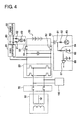
- FIG. 4 is a circuit diagram illustrating the power supply system of the power supply device according to another embodiment of the present invention.
- the present example differs from the first embodiment in that a relay switch 70, an electricity leakage sensing circuit 80, a DC/DC converter 91, and a power generator 92 are provided. All other aspects of the configuration of the second embodiment are the same as in the first embodiment, and descriptions thereof will therefore be quoted as appropriate.
- the power supply system including the power supply device of the present example is provided with an alternating-current power source 10, an inverter 20, a battery 30, a smoothing capacitor 40, a relay switch 50 (first switch), a ground fault sensing circuit 60, a relay switch 70 (second switch), an electricity leakage sensing circuit 80, a DC/DC converter 91, a power generator 92, and a load 110.
- the configurations and connection relationships of the alternating-current power source 10, the inverter 20, the battery 30, the smoothing capacitor 40, the relay switch 50 (first relay), and the ground fault sensing circuit 60 are the same as in the power supply system according to the first embodiment, and therefore will not be described.
- the relay switch 70 is provided in order to cut off the circuit on the reverse side of the inverter 20 from the alternating-current power source 10, i.e., the circuit including the battery 30, the relay switch 50, the ground fault sensing circuit 60, and the electricity leakage sensing circuit 80, from the alternating-current power source 10.
- the relay switch 70 is connected between the alternating-current power source 10 and the inverter 20, and is provided to a power supply line.
- the load 110 is connected between the relay switch 70 and the inverter 20 on the power supply line.
- the electricity leakage sensing circuit 80 is a circuit for sensing electricity leakage in the power generator 92.
- the electricity leakage sensing circuit 80 is connected closer to the inverter 20 than the relay switch 50 via the DC/DC converter 91, and is connected to each of a pair of power supply lines connected between the battery 30 and the inverter 20.
- the electricity leakage sensing circuit 80 has resistors 81, 82 and an electric current sensor 83.
- the resistor 81 is connected to the power supply line on the positive-electrode side
- the resistor 82 is connected to the power supply line on the negative-electrode side.
- the electric current sensor 83 is connected to each of the resistors 81, 82 and is grounded. The electric current sensor 83 detects the electric current on the positive-electrode side from the electric current flowing to the resistor 81, and detects the electric current on the negative-electrode side from the electric current flowing to the resistor 82.
- the electric current difference between the electric current flowing to the resistor 81 and the electric current flowing to the resistor 82 is higher than a predetermined electric current threshold value. Therefore, in the present example, the electric current on the positive-electrode side of the power generator 92 and the electric current on the negative-electrode side of the power generator 92 are detected using the electricity leakage sensing circuit 80, and the deviation of these electric currents is measured, and when the electric current deviation is higher than the electric current threshold value set in advance, it is assessed that electricity leakage is occurring in the power generator 92.
- the DC/DC converter 91 is connected between the power generator 92 and the inverter 20, and is a conversion circuit for converting the electric power generated by the power generator 92 and supplying the electric power to the inverter 20 and the battery 30.
- the power generator 92 uses a self-generation function, and is configured from solar power generation or a fuel cell, for example.
- the power supply system of the present example is provided with the alternating-current power source 10 and the battery 30, and the power generator 92 as a third electric power source.
- the power generator 92 functions as an electric power source for supplying electric power to the load 110, and functions also as an electric power source for charging the battery 30.
- a parallel circuit is formed from the battery 30 and the power generator 92, and this parallel circuit is connected to the alternating-current power source 10 via the relay switch 70 in the present example.
- FIG. 5 is a block diagram illustrating the electric power grid of the power supply system of FIG. 1 .
- thick lines indicate electric power lines (power supply lines) and arrows indicate signal lines.
- the alternating-current power source 10, the relay switch 70, the inverter 20, the relay switch 50, the battery 30, and the power generator 92 are connected by electric power lines.
- the controller 100 controls the alternating-current power source 10, the inverter 20, the battery 30, the relay switch 50, the ground fault sensing circuit 60, the relay switch 70, the electricity leakage sensing circuit 80, and the power generator 92, and is connected by signal lines.
- the controller 100 switches between a normal control mode, a ground fault sensing mode, and a disconnection sensing mode for sensing a disconnection in the electricity leakage sensing circuit 80, and controls the relay switches 50, 70.
- the controller 100 turns on the relay switch 50 and the relay switch 70 and controls the alternating-current power source 10 and other components.
- the controller 100 turns off at least the relay switch 50, and controls the ground fault sensing circuit 60 to sense a ground fault in the battery 30.
- the controller 100 confirms the state of the relay switch 70, and when the relay switch 70 is off, the controller 100 controller performs the disconnection sensing control described below.
- the controller 100 compares the electric current in the relay switch 70 and the electric current threshold value set in advance. When the electric current in the relay switch 70 is lower than the electric current threshold value, the controller 100 turns off the relay switch 70.
- the controller 100 then turns on the relay switch 50, a pulse signal is outputted from the pulse transmitter 63, and a disconnection in the electricity leakage sensing circuit 80 is sensed from the output of the comparator 67.
- the ground fault sensing circuit 60 conducts through the resistors 81, 82 to the grounding point of the electricity leakage sensing circuit 80 via the relay switch 50. Therefore, when there is a disconnection in the electricity leakage sensing circuit 80, the amplitude voltage (response voltage) inputted to the comparator 67 is higher than the reference voltage for the input pulse from the pulse transmitter 63. When there is no disconnection in the electricity leakage sensing circuit 80, the amplitude voltage (response voltage) inputted to the comparator 67 is lower than the reference voltage. The controller 100 can thereby sense that a disconnection has occurred in the electricity leakage sensing circuit 80 if a ground fault is not detected by the ground fault sensing circuit 60 when the relay switch 50 is on.
- the controller 100 When it is assessed that a disconnection has occurred in the electricity leakage sensing circuit 80, the controller 100 notifies the user that a disconnection has occurred.
- FIG. 6 is a flowchart illustrating the procedure of control by the controller 100.
- step S10 control is performed for placing the relay switch 50 and the relay switch 70 in the off state.
- the control procedure for the relay switch 50 in step S10 is the same as the control procedure of steps S1 through S4 in the first embodiment.
- the control procedure of steps S1 through S4 may be substituted as the control procedure for the relay switch 70 in step S10.
- the relay switch 50 and the relay switch 70 may both be placed in the off state when it has been confirmed that the flowing electric current is smaller than a predetermined threshold electric current and the effect of placing the relay switch 50 and relay switch 70 in the off state is minimal.
- steps S 15 through S18 are the same as steps S5 through S8 of the first embodiment, and therefore will not be described.
- step S20 the controller 100 assesses that there is no ground fault in the battery 30, turns on only the relay switch 50 while the relay switch 70 is maintained in the off state, ends the ground fault sensing mode, and transitions to the disconnection sensing mode.
- the ground fault sensing circuit 60 measures the insulation resistance of the electricity leakage sensing circuit 80 by measuring the response voltage for the pulse of the pulse transmitter 63.
- the ground fault sensing circuit 60 detects whether the insulation resistance of the electricity leakage sensing circuit 80 is less than a disconnection sensing threshold value by comparing the corresponding response voltage and the reference voltage through use of the comparator 67.
- the disconnection sensing threshold value is a threshold value for assessing whether there is a disconnection in the electricity leakage sensing circuit 80, and is a value set in advance.
- the disconnection sensing threshold value corresponds to the reference voltage and is set to a value higher than the response voltage for a case in which there is no disconnection in at least one of the resistors 81, 82.
- the disconnection sensing threshold value corresponds to the reference voltage 66, but may be set to a value different from the ground fault sensing threshold value.
- step S23 the controller 100 assesses that there is no disconnection in the electricity leakage sensing circuit 80, turns on the relay switch 70, and ends the disconnection sensing mode.
- step S24 it is assessed that a disconnection has occurred in the electricity leakage sensing circuit 80, and the disconnection sensing mode is ended.
- the electricity leakage sensing circuit 80 is electrically connected, closer to the inverter 20 than the relay switch 50, to a pair of power supply lines connected between the battery 30 and the inverter 20, and when the relay switch 50 is on, disconnection in the electricity leakage sensing circuit 80 is sensed by the ground fault sensing circuit 60. Disconnection can thereby be sensed without providing a separate dedicated mechanism for sensing disconnection in the electricity leakage sensing circuit 80.
- disconnection in the electricity leakage sensing circuit 80 is sensed by the ground fault sensing circuit 60. Disconnection in the electricity leakage sensing circuit 80 can thereby be sensed in a state in which the ground fault sensing circuit 60 is reliably cut off from the alternating-current power source 10.
- the relay switch 70 is off in the present example, but disconnection may also be sensed in a state in which the plurality of switching elements included in the inverter 20 is off.
- the abovementioned relay switch 70 corresponds to the "second switch” of the present invention
- the electricity leakage sensing circuit 80 corresponds to the “electricity leakage sensing means” of the present invention
- the power generator 92 corresponds to the "power generation means” of the present invention.
- the controller 100 specifies a disconnected portion of the electricity leakage sensing circuit 80 by alternately switching the on/off state of a positive-electrode switch 51, which is the switch on the positive-electrode side of the relay switch 50, with the on/off state of a negative-electrode switch 52, which is the switch on the negative-electrode side, and measuring the insulation resistance of the electricity leakage sensing circuit 80.
- the controller 100 turns on the positive-electrode switch 51 of the relay switch 50 and turns off the negative-electrode switch 52 thereof, a pulse signal is outputted from the pulse transmitter 63, and disconnection in the electricity leakage sensing circuit 80 is sensed from the output of the comparator 67.
- the ground fault sensing circuit 60 conducts through the resistor 81 on the positive-electrode side to the grounding point of the electricity leakage sensing circuit 80 via the positive-electrode switch 51.
- the ground fault sensing circuit 60 does not conduct with the resistor 82 on the negative-electrode side.
- the amplitude voltage inputted to the comparator 67 is higher than the reference voltage for the input pulse from the pulse transmitter 63.
- the amplitude voltage inputted to the comparator 67 is higher than the reference voltage also when a disconnection has occurred in the grounding portion of the electricity leakage sensing circuit 80.
- the amplitude voltage inputted to the comparator 67 is lower than the reference voltage. It is thereby possible to sense an abnormality on the positive-electrode side of the electricity leakage sensing circuit 80 in the present example.
- the controller 100 turns off the positive-electrode switch 51 of the relay switch 50 and turns on the negative-electrode switch 52 thereof, a pulse signal is outputted from the pulse transmitter 63, and disconnection in the electricity leakage sensing circuit 80 is sensed from the output of the comparator 67.
- the ground fault sensing circuit 60 When positive-electrode switch 51 is off and the negative-electrode switch 52 is on, the ground fault sensing circuit 60 conducts through the resistor 82 on the negative-electrode side to the grounding point of the ground fault sensing circuit via the negative-electrode switch 52. On the positive-electrode side, since the positive-electrode switch 51 is off, the ground fault sensing circuit 60 does not conduct with the resistor 81 on the positive-electrode side.
- the amplitude voltage inputted to the comparator 67 is higher than the reference voltage for the input pulse from the pulse transmitter 63.
- the amplitude voltage inputted to the comparator 67 is higher than the reference voltage also when a disconnection has occurred in the grounding portion of the electricity leakage sensing circuit 80.
- the amplitude voltage inputted to the comparator 67 is lower than the reference voltage. It is thereby possible to sense an abnormality on the negative-electrode side of the electricity leakage sensing circuit 80 in the present example.
- the controller 100 can then distinguishably sense disconnection in the resistor 81, disconnection in the resistor 82, and disconnection and non-disconnection (normal state) in the grounding portion of the electricity leakage sensing circuit 80 by combining the disconnection sensing result when the positive-electrode switch 71 is on and the negative-electrode switch 72 is off and the disconnection sensing result when the positive-electrode switch 71 is off and the negative-electrode switch 72 is on.
- Table 1 illustrates the results of disconnection sensing with respect to the state of the positive-electrode switch 51 and the state of the negative-electrode switch 52, and to the result of measuring the insulation resistance.
- Table 1 Positive-electrode switch/Negative-electrode switch ON/OFF ⁇ ⁇ Positive-electrode switch/Negative-electrode switch OFF/ON ⁇ Normal Positive-electrode side abnormality ⁇ Negative-electrode side abnormality Grounding abnormality
- ON and OFF for the positive-electrode switch/negative-electrode switch indicate the on state and off state, respectively, of the switches 51, 52.
- ON/OFF indicates the on state for the positive-electrode switch 51 and the off state for the negative-electrode switch 52.
- OFF/ON indicates the off state for the positive-electrode switch 51 and the on state for the negative-electrode switch 52.
- a circle indicates a case in which the insulation resistance measured by the ground fault sensing circuit 60 is less than the disconnection sensing threshold value, and an x-mark indicates a case in which the insulation resistance measured by the ground fault sensing circuit 60 is equal to or greater than the disconnection sensing threshold value.
- the controller 100 assesses that a disconnection has occurred in the resistor 81, and assesses that there is an abnormality on the positive-electrode side of the electricity leakage sensing circuit 80.
- the controller 100 assesses that a disconnection has occurred in the resistor 82, and assesses that there is an abnormality on the negative-electrode side of the electricity leakage sensing circuit 80.
- the controller 100 assesses that a disconnection has occurred in the grounding portion, and assesses that there is an abnormality in the grounding portion of the electricity leakage sensing circuit 80.
- the switches are switched so that the on/off state of the positive-electrode switch 51 and the on/off state of the negative-electrode switch 52 are interchanged, the reference voltage and the voltage sensed by the ground fault sensing circuit are compared, and sensing can be performed after distinguishing among abnormality in the positive-electrode side, abnormality in the negative-electrode side, abnormality in the grounding of the electricity leakage sensing circuit 80, and normal operation of the electricity leak sensing circuit according to the conditions illustrated in Table 1.
Landscapes
- Physics & Mathematics (AREA)
- General Physics & Mathematics (AREA)
- Testing Of Short-Circuits, Discontinuities, Leakage, Or Incorrect Line Connections (AREA)
- Emergency Protection Circuit Devices (AREA)
Abstract
Description
- The present invention relates to a power supply device.
- The present application claims right of priority based on Japanese Patent Application
2012-179789, filed on August 14,2012 - A ground fault detection device for detecting ground faults in a direct-current power source grid comprising a battery group is known in which a detection resistor and a coupling capacitor for direct-current cutoff are connected between a pulse signal generating means and a ground fault detection terminal connected to a direct-current negative electrode feed line, and a reduction in insulation resistance during a ground fault is sensed from the difference between a reference voltage and the detected voltage of a pulse signal occurring at a point of connection of the detection resistor and the coupling capacitor (Patent Document 1).
- Patent Document 1: Japanese Laid-Open Patent Application No.
2004-138434 - However, in a power supply system in which the direct-current power source grid described above is connected to alternating-current grid electric power via an inverter, and a direct-current power source is charged by the alternating-current grid electric power, the alternating-current grid electric power is grounded. The conventional ground fault detection device described above therefore has the drawback of being incapable of sensing a reduction in insulation resistance during a ground fault.
- An object of the present invention is to provide a power supply device provided with a grounded alternating-current power source and a secondary cell connected to the alternating-current power source, the power supply device being capable of detecting a ground fault in the secondary cell.
- In the present invention for achieving the abovementioned object, a first switch for selectively connecting or cutting off a secondary cell and an alternating-current power source is connected between the secondary cell and the alternating-current power source, a ground fault sensing means for sensing a ground fault in the secondary cell is connected closer to the secondary cell than the first switch, and a ground fault in the secondary cell is sensed by the ground fault sensing means in a state in which the first switch is off.
- Through the present invention, a grounding portion of the alternating-current power source and a circuit portion for sensing of a ground fault in the secondary cell by the ground fault sensing means are cut off by the turning off of the first switch. A ground fault in the secondary cell can therefore be sensed without affecting the grounding of the alternating-current power source.
-
- [
Figure 1 ] Circuit diagram of the power supply system including the power supply device according to an embodiment of the present invention. - [
Figure 2 ] Block diagram of the power supply system inFIG. 1 . - [
Figure 3 ] Flowchart illustrating the procedure of control performed by the controller ofFIG. 2 . - [
Figure 4 ] Circuit diagram of the power supply system including the power supply device according to another embodiment of the present invention. - [
Figure 5 ] Block diagram of the power supply system inFIG. 4 . - [
Figure 6 ] Flowchart illustrating the procedure of control performed by the controller inFIG. 5 . - Embodiments of the present invention will be described below with reference to the drawings.
-
FIG. 1 is a circuit diagram illustrating the power supply system of the power supply device according to an embodiment of the present invention. The power supply device of the present example is applied to a household or commercial power supply system which uses an alternating-current power source as one current source. - The power supply system including the power supply device of the present example is provided with an alternating-
current power source 10, aninverter 20, a battery (secondary cell) 30, asmoothing capacitor 40, a relay switch 50 (first switch), and a groundfault sensing circuit 60. The alternating-current power source 10 is an electric power source for supplying electric power to a load not illustrated in the drawing, and is also an electric power source for supplying charging electric power to thebattery 30 via theinverter 20. The alternating-current power source 10 includes a transformer, and is grounded by connecting a neutral point of the secondary side of the transformer to ground. The transformer is a common transformer provided to a household or facility to transform alternating-current electric power supplied from a power company for output, for example. - The
inverter 20 is an AC/DC conversion circuit in which a plurality of switching elements is connected in bridged fashion, and is a conversion circuit for converting alternating-current electric power supplied from the alternating-current power source 10 into direct-current electric power and supplying the direct-current electric power to thebattery 30. Theinverter 20 converts direct-current electric power outputted from thebattery 30 into alternating-current electric power and supplies electric power to aload 110. Theinverter 20 is connected to a pair of power supply lines connected to the alternating-current power source 10 and is connected between the alternating-current power source 10 and thebattery 30. - The
battery 30 is a storage cell in which a plurality of lithium-ion cells or other secondary cells is connected. In the power supply system of the present example, thebattery 30 is a cell for storing electric power to be supplied to a load not illustrated in the drawing. In the present example, electric power is controlled so that thebattery 30 is charged by electric power from the alternating-current power source 10 during late-night hours in which electric utility rates are inexpensive, and the electric power saved in thebattery 30 is supplied to a load during daytime hours, for example. - The
smoothing capacitor 40 is a capacitor for rectifying the electric power supplied to thebattery 30 from theinverter 20, and is connected between the positive-electrode side and negative-electrode side of the pair of power supply lines, and connected between theinverter 20 and therelay switch 50. - The
relay switch 50 is a switch for providing conduction and cutoff between thebattery 30 and the alternating-current power source 10, and is connected between theinverter 20 and thebattery 30. When therelay switch 50 is off, electric power from thebattery 30 is not supplied to theinverter 20, and electric power from theinverter 20 is not supplied to thebattery 30. - The ground
fault sensing circuit 60 is a circuit for sensing a ground fault in thebattery 30, and is connected on thebattery 30 side of therelay switch 50. In the example illustrated inFIG. 1 , the groundfault sensing circuit 60 is connected to an electric power line for connecting a negative electrode of thebattery 30 and a junction on the negative-electrode side of therelay switch 50. In other words, the groundfault sensing circuit 60 is connected between thebattery 30 and therelay switch 50, and when therelay switch 50 is off, the groundfault sensing circuit 60 therefore becomes able to sense a ground fault (i.e., a decrease in insulation resistance) by detecting the insulation resistance of thebattery 30. When therelay switch 50 is on, conduction occurs to the ground of the alternating-current power source 10 via therelay switch 50 and theinverter 20, and it is therefore impossible to distinguish whether the smallness of the detected insulation resistance is due to a decrease in insulation resistance of thebattery 30 or a decrease in insulation resistance due to grounding of the alternating-current power source 10, and a ground fault in thebattery 30 cannot be sensed. - The ground
fault sensing circuit 60 hascapacitors resistors pulse transmitter 63, and acomparator 67. One end of thecapacitor 61 is connected to the battery 30 (to an electric power line connected to an electrode terminal of the battery 30), and the other end is connected to thepulse transmitter 63 via theresistor 62. In other words, thepulse transmitter 63 is connected to the power supply line via a series circuit of thecapacitor 61 and theresistor 62. A low-pass filter comprising the series circuit of theresistor 64 and thecapacitor 65 is connected to the connection point (measurement point) between thecapacitor 61 and theresistor 62. The input side of thecomparator 67 is connected to areference voltage 66 and the connection point between theresistor 64 and thecapacitor 65, and the output side of thecomparator 67 is connected to a controller described hereinafter. - In the case of sensing a ground fault in the
battery 30 through use of the groundfault sensing circuit 60, a pulse which is a voltage signal having a predetermined amplitude is outputted from thepulse transmitter 63 and inputted to the battery 30 (to an electric power line connected to an electrode terminal of the battery 30) via thecapacitor 61. A voltage variation at the other-end side of thecapacitor 61, i.e., on the side of the point of connection to the resistor 62 (at the measurement point), in accordance with the insulation resistance of thebattery 30 is manifested as an amplitude variation in the input voltage inputted to a comparator 97. Therefore, by comparing the amplitude voltage and the reference voltage, the groundfault sensing circuit 60 determines whether the insulation resistance of thebattery 30 has decreased. The reference voltage is a voltage threshold value set in advance that corresponds to the insulation resistance for sensing a ground fault in thebattery 30. In other words, the amplitude (amplitude voltage) of the input voltage inputted to the comparator 97 corresponds to the insulation voltage, and a decrease in the insulation resistance of the battery 30 (a ground fault) is therefore detected by comparing the amplitude voltage with the reference voltage. In brief, the groundfault sensing circuit 60 can also be considered to detect the insulation resistance (i.e., the amplitude voltage) and compare the detected insulation resistance with an insulation resistance that serves as a reference for sensing a ground fault (i.e., a reference voltage) to sense the occurrence of a ground fault. - When a ground fault is not occurring in the
battery 30, the amplitude voltage (response voltage) inputted to thecomparator 67 is higher than the reference voltage. When a ground fault is occurring in thebattery 30, the insulation resistance of thebattery 30 decreases (e.g., substantially to zero), and the amplitude voltage inputted to thecomparator 67 is therefore lower than the reference voltage. The groundfault sensing circuit 60 thereby senses a ground fault in thebattery 30 by comparing the reference voltage and the amplitude voltage for the input pulse of thepulse transmitter 63. Theload 110 is an electrical equipment load provided to a household or facility that is driven by alternating-current electric power from the alternating-current power source 10 or alternating-current electric power outputted from theinverter 20. - The electric power grid of the power supply system of the present example will next be described using
FIG. 2. FIG. 2 is a block diagram illustrating the electric power grid of the power supply system ofFIG. 1 . InFIG. 2 , thick lines indicate electric power lines (power supply lines) and arrows indicate signal lines. - The alternating-
current power source 10, theinverter 20, therelay switch 50, theload 110, and thebattery 30 are connected by electric power lines. Acontroller 100 controls the alternating-current power source 10, theinverter 20, thebattery 30, therelay switch 50, and the groundfault sensing circuit 60, and is connected by signal lines. - Control of the power supply system of the present example will next be described. The
controller 100 switches between a normal control mode and a ground fault sensing mode for sensing a ground fault in thebattery 30, and controls therelay switch 50 and other components. The normal control mode will first be described. - In the normal control mode, the
controller 100 turns on therelay switch 50 and creates a state in which electric power from thebattery 30 is supplied to the load 110 (via the inverter 20), electric power from the alternating-current power source 10 is supplied to the battery 30 (via the inverter 20), and it is possible to charge thebattery 30. Thecontroller 100 controls the alternating-current power source 10, theinverter 20, and thebattery 30 in accordance with the demand electric power, a time block, or another factor that corresponds to the usage status of the load. For example, in daytime or other time blocks in which electric utility rates are high, thecontroller 100 supplies electric power from thebattery 30 to theload 110. When the amount of electric power demanded by theload 110 is large and cannot be covered solely by the electric power of thebattery 30, thecontroller 100 supplies electric power from the alternating-current power source 10 to theload 110 in addition to the electric power of thebattery 30. - In time blocks in which electric utility rates are low, the
controller 100 charges thebattery 30 while supplying electric power from the alternating-current power source 10 to theload 110. During charging of thebattery 30, thecontroller 100 manages the charging state of thebattery 30 and controls the charging electric power supplied from theinverter 20 to thebattery 30 so that thebattery 30 is not overcharged. Thecontroller 100 thereby manages electric power in the power supply system of the present example. - The ground fault sensing mode will next be described. In a state in which the
relay switch 50 is on as described above, when a pulse is issued from thepulse transmitter 63, voltages are compared by thecomparator 67, and the insulation resistance of thebattery 30 is thereby detected in order for the ground fault sensing means 60 to sense a ground fault in thebattery 30, grounding of the alternating-current power source 10 causes the amplitude voltage inputted to thecomparator 67 to fall below the voltage threshold value. The insulation resistance of thebattery 30 therefore decreases even when there is no ground fault in thebattery 30, and it is possible for a ground fault in thebattery 30 to be erroneously sensed. Control is therefore performed in the present example so that therelay switch 50 is placed in the off state prior to ground fault sensing by the groundfault sensing circuit 60. - When the ground fault sensing mode is to be executed, the
controller 100 first confirms the on or off state of therelay switch 50. When therelay switch 50 is off, thecontroller 100 activates the groundfault sensing circuit 60 and senses a ground fault in thebattery 30 by measuring the insulation resistance of thebattery 30. - During execution of the ground fault sensing mode, when the
relay switch 50 is on, thecontroller 100 detects the electric current flowing through therelay switch 50 and determines whether the detected electric current is lower than a predetermined electric current threshold value. The electric current threshold value is set in advance and is an electric current having the threshold value necessary for turning off therelay switch 50. The detected electric current may be detected by connecting an electric current sensor to the power supply line to which therelay switch 50 is connected. Alternatively, since the electric power of the alternating-current power source 10 and the charging/discharging electric power of thebattery 30 are controlled in accordance with the demand electric power of the load, thecontroller 100 may detect the electric current flowing to therelay switch 50 from the charging/discharging electric power of thebattery 30. - When the detected electric current in the
relay switch 50 is lower than the electric current threshold value (e.g., when the detected electric current is substantially zero), therelay switch 50 is turned off, and even when the supply of electric power from thebattery 30 to theload 110 is cut off, because the decrease in electric power supplied to theload 110 due to the cutoff is small, theload 110 can be driven by the electric power from the alternating-current power source 10. When thebattery 30 is being charged, thebattery 30 may be charged after ground fault sensing is completed. Consequently, when the detected electric current in therelay switch 50 is lower than the electric current threshold value, thecontroller 100 turns off therelay switch 50, activates the groundfault sensing circuit 60, and performs ground fault detection in thebattery 30. - When the detected electric current in the
relay switch 50 is equal to or greater than the electric current threshold value, thecontroller 100 detects the electric current in therelay switch 50 while leaving therelay switch 50 in the on state. At the instant that the detected electric current in therelay switch 50 becomes lower than the electric current threshold value, thecontroller 100 turns off the relay switch and senses ground faults in thebattery 30. - When it is assessed that a ground fault is occurring in the
battery 30, thecontroller 100 restricts charging and discharging of thebattery 30 by maintaining therelay switch 50 in the off state while notifying a user that a ground fault has occurred. - The procedure of control by the
controller 100 in the ground fault sensing mode will next be described usingFIG. 3. FIG. 3 is a flowchart illustrating the procedure of control by thecontroller 100. - The
controller 100 performs the control process illustrated inFIG. 3 when executing the ground fault sensing mode. First, in step S1, thecontroller 100 confirms whether the relay switch 50 (first switch) is off. When therelay switch 50 is off, the process proceeds to step S5. - When the
relay switch 50 is not off, thecontroller 100 detects the electric current in the relay switch 50 (step S2). In step S3, thecontroller 100 compares the detected electric current in therelay switch 50 and the electric current threshold value. When the detected electric current in therelay switch 50 is equal to or greater than the electric current threshold value, the process returns to step S2, and the electric current in therelay switch 50 is again detected. - When the detected electric current is lower than the electric current threshold value, the
controller 100 turns off the relay switch 50 (step S4). - In step S5, the
controller 100 activates the groundfault sensing circuit 60. In step S6, the groundfault sensing circuit 60 measures the insulation resistance of thebattery 30 by measuring the response voltage for the pulse of thepulse transmitter 63. - In step S7, the ground
fault sensing circuit 60 detects whether the insulation resistance is equal to or greater than a ground fault sensing threshold value by comparing the corresponding response voltage and the reference voltage through use of thecomparator 67. The ground fault sensing threshold value corresponds to thereference voltage 66. When the insulation resistance is equal to or greater than the ground fault sensing threshold value, thecontroller 100 in step S8 assesses that there is no ground fault in thebattery 30, turns on therelay switch 50, and ends the ground fault sensing mode. - When the insulation resistance is less than the ground fault sensing threshold value, the
controller 100 in step S9 assesses from the result of comparison by thecomparator 67 that a ground fault is occurring in thebattery 30, notifies the user that a ground fault has occurred, and ends the ground fault sensing mode. - As described above, in the present example, a ground fault in the
battery 30 is sensed by the groundfault sensing circuit 60 when therelay switch 50 connected between the alternating-current power source 10 and thebattery 30 is off. In the present example, a ground fault in thebattery 30 can thereby be sensed in a power supply device for supplying electric power from the grounded alternating-current power source 10 to thebattery 30 via the inverter. - In a possible method for sensing a ground fault in the
battery 30, a ground fault is sensed by an operator using a megohm tester after placing thebattery 30 in an insulated state (a state in which the alternating-current power source 10 and thebattery 30 are electrically isolated). However, because a ground fault can be sensed without use of a megohm tester in the present example, the number of man-hours involved in ground fault sensing can be reduced. - In another possible method, during ground fault sensing in the
battery 30, ground fault sensing in thebattery 30 is performed after a transformer has been provided between theinverter 20 and thebattery 30 in order to ensure an insulated state in thebattery 30. However, when a transformer is provided, the size of the system is increased, cost of the power supply device increases, and the operating noise of the power supply device become significant. However, an insulated state is ensured in the present example by turning of therelay switch 50, and the abovementioned transformer can therefore be omitted. - In the present invention, the
controller 100 turns off all of the plurality of switching elements included in theinverter 20, and ground fault sensing in thebattery 30 may therefore be performed by the groundfault sensing circuit 60 in a state in which the alternating-current power source 10 and thebattery 30 are electrically isolated from each other. When the plurality of switching elements of theinverter 20 are turned off, the groundfault sensing circuit 60 is cut off from the alternating-current power source 10, and it is therefore possible to prevent the groundfault sensing circuit 60 from erroneously sensing the grounding of the alternating-current power source 10 as a ground fault in thebattery 30. - In the present invention, the
controller 100 may also be caused to turn off therelay switch 50 at a predetermined cycle, and control the groundfault sensing circuit 60 to sense ground faults in thebattery 30. The predetermined cycle is set in advance, and is set to one day (24 hours), for example. It is thereby possible to periodically perform ground fault sensing in thebattery 30 in the present example. - The timing at which the
relay switch 50 is turned off at a predetermined cycle may be set to late-night hours, for example, in which charging/discharging control of thebattery 30 is not being performed. - In the present invention, the
controller 100 may measure the time elapsed from the last time ground fault sensing was performed, and when the measured elapsed time exceeds a limit time set in advance, thecontroller 100 may turn off therelay switch 50 and cause ground faults in thebattery 30 to be sensed. Measurement of the elapsed time may be reset when the detected electric current in therelay switch 50 falls below the electric current threshold value and ground fault sensing is performed before the measured elapsed time has exceeded the limit time. It is thereby possible to periodically perform ground fault sensing in thebattery 30 in the present example. - Specifically, the
controller 100 turns off therelay switch 50 and causes ground faults in thebattery 30 to be sensed at least once per a predetermined time. Through this configuration, even in a continued state in which therelay switch 50 is on, therelay switch 50 can be turned off and ground faults in thebattery 30 can be sensed. As a result, a highly safe system can be provided. - In the present example, when the time block in which the alternating-
current power source 10 is used is a nighttime electric power time block (an intra-day time block in which electric utility rates decrease), thecontroller 100 may turn off therelay switch 50, and ground faults in thebattery 30 may be sensed by the groundfault sensing circuit 60. Through this configuration, since therelay switch 50 is turned off during the nighttime electric power time block for thebattery 30, ground faults in thebattery 30 can be sensed while the effect of using the alternating-current power source 10 on the electric utility rate is minimized when the amount of electric power that cannot be supplied to theload 110 from thebattery 30 is supplemented by electric power from the alternating-current power source 10. As a result, a highly safe system can be provided without increasing the economic burden on the user. - The
abovementioned relay switch 50 corresponds to the "first switch" of the present invention, the groundfault sensing circuit 60 corresponds to the "ground fault sensing means" of the present invention, and thecontroller 100 corresponds to the "control means" of the present invention. -
FIG. 4 is a circuit diagram illustrating the power supply system of the power supply device according to another embodiment of the present invention. The present example differs from the first embodiment in that arelay switch 70, an electricityleakage sensing circuit 80, a DC/DC converter 91, and apower generator 92 are provided. All other aspects of the configuration of the second embodiment are the same as in the first embodiment, and descriptions thereof will therefore be quoted as appropriate. - As illustrated in
FIG. 4 , the power supply system including the power supply device of the present example is provided with an alternating-current power source 10, aninverter 20, abattery 30, a smoothingcapacitor 40, a relay switch 50 (first switch), a groundfault sensing circuit 60, a relay switch 70 (second switch), an electricityleakage sensing circuit 80, a DC/DC converter 91, apower generator 92, and aload 110. The configurations and connection relationships of the alternating-current power source 10, theinverter 20, thebattery 30, the smoothingcapacitor 40, the relay switch 50 (first relay), and the groundfault sensing circuit 60 are the same as in the power supply system according to the first embodiment, and therefore will not be described. - The
relay switch 70 is provided in order to cut off the circuit on the reverse side of theinverter 20 from the alternating-current power source 10, i.e., the circuit including thebattery 30, therelay switch 50, the groundfault sensing circuit 60, and the electricityleakage sensing circuit 80, from the alternating-current power source 10. Therelay switch 70 is connected between the alternating-current power source 10 and theinverter 20, and is provided to a power supply line. Theload 110 is connected between therelay switch 70 and theinverter 20 on the power supply line. - The electricity
leakage sensing circuit 80 is a circuit for sensing electricity leakage in thepower generator 92. The electricityleakage sensing circuit 80 is connected closer to theinverter 20 than therelay switch 50 via the DC/DC converter 91, and is connected to each of a pair of power supply lines connected between thebattery 30 and theinverter 20. - the electricity
leakage sensing circuit 80 hasresistors current sensor 83. Theresistor 81 is connected to the power supply line on the positive-electrode side, and theresistor 82 is connected to the power supply line on the negative-electrode side. The electriccurrent sensor 83 is connected to each of theresistors current sensor 83 detects the electric current on the positive-electrode side from the electric current flowing to theresistor 81, and detects the electric current on the negative-electrode side from the electric current flowing to theresistor 82. - When electricity leakage occurs in the
power generator 92, the electric current difference between the electric current flowing to theresistor 81 and the electric current flowing to theresistor 82 is higher than a predetermined electric current threshold value. Therefore, in the present example, the electric current on the positive-electrode side of thepower generator 92 and the electric current on the negative-electrode side of thepower generator 92 are detected using the electricityleakage sensing circuit 80, and the deviation of these electric currents is measured, and when the electric current deviation is higher than the electric current threshold value set in advance, it is assessed that electricity leakage is occurring in thepower generator 92. - The DC/
DC converter 91 is connected between thepower generator 92 and theinverter 20, and is a conversion circuit for converting the electric power generated by thepower generator 92 and supplying the electric power to theinverter 20 and thebattery 30. - The
power generator 92 uses a self-generation function, and is configured from solar power generation or a fuel cell, for example. Specifically, the power supply system of the present example is provided with the alternating-current power source 10 and thebattery 30, and thepower generator 92 as a third electric power source. Thepower generator 92 functions as an electric power source for supplying electric power to theload 110, and functions also as an electric power source for charging thebattery 30. Through this configuration, a parallel circuit is formed from thebattery 30 and thepower generator 92, and this parallel circuit is connected to the alternating-current power source 10 via therelay switch 70 in the present example. - The electric power grid of the power supply system of the present example will next be described using
FIG. 5. FIG. 5 is a block diagram illustrating the electric power grid of the power supply system ofFIG. 1 . InFIG. 5 , thick lines indicate electric power lines (power supply lines) and arrows indicate signal lines. - The alternating-
current power source 10, therelay switch 70, theinverter 20, therelay switch 50, thebattery 30, and thepower generator 92 are connected by electric power lines. Thecontroller 100 controls the alternating-current power source 10, theinverter 20, thebattery 30, therelay switch 50, the groundfault sensing circuit 60, therelay switch 70, the electricityleakage sensing circuit 80, and thepower generator 92, and is connected by signal lines. - Control of the power supply system of the present example will next be described. The
controller 100 switches between a normal control mode, a ground fault sensing mode, and a disconnection sensing mode for sensing a disconnection in the electricityleakage sensing circuit 80, and controls the relay switches 50, 70. - In the normal control mode, the
controller 100 turns on therelay switch 50 and therelay switch 70 and controls the alternating-current power source 10 and other components. - In the ground fault sensing mode, the
controller 100 turns off at least therelay switch 50, and controls the groundfault sensing circuit 60 to sense a ground fault in thebattery 30. - In the disconnection sensing mode, the
controller 100 confirms the state of therelay switch 70, and when therelay switch 70 is off, thecontroller 100 controller performs the disconnection sensing control described below. When therelay switch 70 is on, thecontroller 100 compares the electric current in therelay switch 70 and the electric current threshold value set in advance. When the electric current in therelay switch 70 is lower than the electric current threshold value, thecontroller 100 turns off therelay switch 70. - In the state in which the
relay switch 70 is off, thecontroller 100 then turns on therelay switch 50, a pulse signal is outputted from thepulse transmitter 63, and a disconnection in the electricityleakage sensing circuit 80 is sensed from the output of thecomparator 67. - When the
relay switch 50 is on, the groundfault sensing circuit 60 conducts through theresistors leakage sensing circuit 80 via therelay switch 50. Therefore, when there is a disconnection in the electricityleakage sensing circuit 80, the amplitude voltage (response voltage) inputted to thecomparator 67 is higher than the reference voltage for the input pulse from thepulse transmitter 63. When there is no disconnection in the electricityleakage sensing circuit 80, the amplitude voltage (response voltage) inputted to thecomparator 67 is lower than the reference voltage. Thecontroller 100 can thereby sense that a disconnection has occurred in the electricityleakage sensing circuit 80 if a ground fault is not detected by the groundfault sensing circuit 60 when therelay switch 50 is on. - When it is assessed that a disconnection has occurred in the electricity
leakage sensing circuit 80, thecontroller 100 notifies the user that a disconnection has occurred. - The control performed by the
controller 100 in the ground fault sensing mode and the disconnection sensing mode will next be described usingFIG. 6. FIG. 6 is a flowchart illustrating the procedure of control by thecontroller 100. - In step S10, control is performed for placing the
relay switch 50 and therelay switch 70 in the off state. The control procedure for therelay switch 50 in step S10 is the same as the control procedure of steps S1 through S4 in the first embodiment. The control procedure of steps S1 through S4 may be substituted as the control procedure for therelay switch 70 in step S10. Specifically, therelay switch 50 and therelay switch 70 may both be placed in the off state when it has been confirmed that the flowing electric current is smaller than a predetermined threshold electric current and the effect of placing therelay switch 50 andrelay switch 70 in the off state is minimal. - After the control process of step S10, steps S 15 through S18 are the same as steps S5 through S8 of the first embodiment, and therefore will not be described.
- When the determination of step S 17 is that the insulation resistance is equal to or greater than the ground fault sensing threshold value, in step S20, the
controller 100 assesses that there is no ground fault in thebattery 30, turns on only therelay switch 50 while therelay switch 70 is maintained in the off state, ends the ground fault sensing mode, and transitions to the disconnection sensing mode. - In step S21, the ground
fault sensing circuit 60 measures the insulation resistance of the electricityleakage sensing circuit 80 by measuring the response voltage for the pulse of thepulse transmitter 63. In step S22, the groundfault sensing circuit 60 detects whether the insulation resistance of the electricityleakage sensing circuit 80 is less than a disconnection sensing threshold value by comparing the corresponding response voltage and the reference voltage through use of thecomparator 67. The disconnection sensing threshold value is a threshold value for assessing whether there is a disconnection in the electricityleakage sensing circuit 80, and is a value set in advance. Consequently, the disconnection sensing threshold value corresponds to the reference voltage and is set to a value higher than the response voltage for a case in which there is no disconnection in at least one of theresistors reference voltage 66, but may be set to a value different from the ground fault sensing threshold value. - When the insulation resistance is less than the disconnection sensing threshold value, in step S23, the
controller 100 assesses that there is no disconnection in the electricityleakage sensing circuit 80, turns on therelay switch 70, and ends the disconnection sensing mode. - When the insulation resistance is equal to or greater than the disconnection sensing threshold value, in step S24, it is assessed that a disconnection has occurred in the electricity
leakage sensing circuit 80, and the disconnection sensing mode is ended. - As described above, in the present example, the electricity
leakage sensing circuit 80 is electrically connected, closer to theinverter 20 than therelay switch 50, to a pair of power supply lines connected between thebattery 30 and theinverter 20, and when therelay switch 50 is on, disconnection in the electricityleakage sensing circuit 80 is sensed by the groundfault sensing circuit 60. Disconnection can thereby be sensed without providing a separate dedicated mechanism for sensing disconnection in the electricityleakage sensing circuit 80. - In the present example, when the
relay switch 70 is off, disconnection in the electricityleakage sensing circuit 80 is sensed by the groundfault sensing circuit 60. Disconnection in the electricityleakage sensing circuit 80 can thereby be sensed in a state in which the groundfault sensing circuit 60 is reliably cut off from the alternating-current power source 10. - In the case of sensing disconnection in the electricity
leakage sensing circuit 80 through use of the groundfault sensing circuit 60, therelay switch 70 is off in the present example, but disconnection may also be sensed in a state in which the plurality of switching elements included in theinverter 20 is off. - The
abovementioned relay switch 70 corresponds to the "second switch" of the present invention, the electricityleakage sensing circuit 80 corresponds to the "electricity leakage sensing means" of the present invention, and thepower generator 92 corresponds to the "power generation means" of the present invention. - The power supply system of the power supply device according to another embodiment of the present invention will next be described. In the present example, a portion of the control of disconnection sensing in the electricity
leakage sensing circuit 80 by the groundfault sensing circuit 60 differs from that of the second embodiment. All other aspects of the configuration of the third embodiment are the same as in the second embodiment, and descriptions thereof will therefore be quoted as appropriate. - When the
relay switch 70 is off, thecontroller 100 specifies a disconnected portion of the electricityleakage sensing circuit 80 by alternately switching the on/off state of a positive-electrode switch 51, which is the switch on the positive-electrode side of therelay switch 50, with the on/off state of a negative-electrode switch 52, which is the switch on the negative-electrode side, and measuring the insulation resistance of the electricityleakage sensing circuit 80. - The
controller 100 turns on the positive-electrode switch 51 of therelay switch 50 and turns off the negative-electrode switch 52 thereof, a pulse signal is outputted from thepulse transmitter 63, and disconnection in the electricityleakage sensing circuit 80 is sensed from the output of thecomparator 67. - When positive-
electrode switch 51 is on and the negative-electrode switch 52 is off, the groundfault sensing circuit 60 conducts through theresistor 81 on the positive-electrode side to the grounding point of the electricityleakage sensing circuit 80 via the positive-electrode switch 51. On the negative-electrode side, since the negative-electrode switch 52 is off, the groundfault sensing circuit 60 does not conduct with theresistor 82 on the negative-electrode side. - In this state, when there is a disconnection in the
resistor 81 portion, the amplitude voltage inputted to thecomparator 67 is higher than the reference voltage for the input pulse from thepulse transmitter 63. Similarly, the amplitude voltage inputted to thecomparator 67 is higher than the reference voltage also when a disconnection has occurred in the grounding portion of the electricityleakage sensing circuit 80. When there is no disconnection in theresistor 81 portion and the grounding portion of the electricityleakage sensing circuit 80, the amplitude voltage inputted to thecomparator 67 is lower than the reference voltage. It is thereby possible to sense an abnormality on the positive-electrode side of the electricityleakage sensing circuit 80 in the present example. - The
controller 100 turns off the positive-electrode switch 51 of therelay switch 50 and turns on the negative-electrode switch 52 thereof, a pulse signal is outputted from thepulse transmitter 63, and disconnection in the electricityleakage sensing circuit 80 is sensed from the output of thecomparator 67. - When positive-
electrode switch 51 is off and the negative-electrode switch 52 is on, the groundfault sensing circuit 60 conducts through theresistor 82 on the negative-electrode side to the grounding point of the ground fault sensing circuit via the negative-electrode switch 52. On the positive-electrode side, since the positive-electrode switch 51 is off, the groundfault sensing circuit 60 does not conduct with theresistor 81 on the positive-electrode side. - In this state, when there is a disconnection in the
resistor 82 portion, the amplitude voltage inputted to thecomparator 67 is higher than the reference voltage for the input pulse from thepulse transmitter 63. Similarly, the amplitude voltage inputted to thecomparator 67 is higher than the reference voltage also when a disconnection has occurred in the grounding portion of the electricityleakage sensing circuit 80. When there is no disconnection in theresistor 82 portion and the grounding portion of the electricityleakage sensing circuit 80, the amplitude voltage inputted to thecomparator 67 is lower than the reference voltage. It is thereby possible to sense an abnormality on the negative-electrode side of the electricityleakage sensing circuit 80 in the present example. - The
controller 100 can then distinguishably sense disconnection in theresistor 81, disconnection in theresistor 82, and disconnection and non-disconnection (normal state) in the grounding portion of the electricityleakage sensing circuit 80 by combining the disconnection sensing result when the positive-electrode switch 71 is on and the negative-electrode switch 72 is off and the disconnection sensing result when the positive-electrode switch 71 is off and the negative-electrode switch 72 is on. - Table 1 illustrates the results of disconnection sensing with respect to the state of the positive-
electrode switch 51 and the state of the negative-electrode switch 52, and to the result of measuring the insulation resistance.Table 1 Positive-electrode switch/Negative-electrode switch ON/OFF ○ × Positive-electrode switch/Negative-electrode switch OFF/ON ○ Normal Positive-electrode side abnormality × Negative-electrode side abnormality Grounding abnormality - In Table 1, ON and OFF for the positive-electrode switch/negative-electrode switch indicate the on state and off state, respectively, of the
switches electrode switch 51 and the off state for the negative-electrode switch 52. For the positive-electrode switch and negative-electrode switch, OFF/ON indicates the off state for the positive-electrode switch 51 and the on state for the negative-electrode switch 52. A circle indicates a case in which the insulation resistance measured by the groundfault sensing circuit 60 is less than the disconnection sensing threshold value, and an x-mark indicates a case in which the insulation resistance measured by the groundfault sensing circuit 60 is equal to or greater than the disconnection sensing threshold value. - As illustrated in Table 1, when the positive-
electrode switch 51 is on and the negative-electrode switch 52 is off, and the amplitude voltage (corresponding to the voltage sensed by the ground fault sensing circuit 60) inputted to thecomparator 67 is less than the reference voltage for the input pulse from thepulse transmitter 63, and when the positive-electrode switch 51 is off and the negative-electrode switch 52 is on, and the amplitude voltage inputted to thecomparator 67 is less than the reference voltage, the resistance values of theresistors controller 100 therefore assesses that the electricityleakage sensing circuit 80 is normal. - When the positive-
electrode switch 51 is on and the negative-electrode switch 52 is off, and the amplitude voltage inputted to thecomparator 67 is equal to or greater than the reference voltage, and when the positive-electrode switch 51 is off and the negative-electrode switch 52 is on, and the amplitude voltage inputted to thecomparator 67 is less than the reference voltage, the resistance values of theresistor 82 and the grounding portion are not elevated, but the resistance value of theresistor 81 is elevated. Therefore, thecontroller 100 assesses that a disconnection has occurred in theresistor 81, and assesses that there is an abnormality on the positive-electrode side of the electricityleakage sensing circuit 80. - When the positive-
electrode switch 51 is on and the negative-electrode switch 52 is off, and the amplitude voltage inputted to thecomparator 67 is less than the reference voltage, and when the positive-electrode switch 51 is off and the negative-electrode switch 52 is on, and the amplitude voltage inputted to thecomparator 67 is equal to or greater than the reference voltage, the resistance values of theresistor 81 and the grounding portion are not elevated, but the resistance value of theresistor 82 is elevated. Therefore, thecontroller 100 assesses that a disconnection has occurred in theresistor 82, and assesses that there is an abnormality on the negative-electrode side of the electricityleakage sensing circuit 80. - When the positive-
electrode switch 51 is on and the negative-electrode switch 52 is off, and the amplitude voltage inputted to thecomparator 67 is equal to or greater than the reference voltage, and when the positive-electrode switch 51 is off and the negative-electrode switch 52 is on, and the amplitude voltage inputted to thecomparator 67 is equal to or greater than the reference voltage, the resistance values of theresistors controller 100 assesses that a disconnection has occurred in the grounding portion, and assesses that there is an abnormality in the grounding portion of the electricityleakage sensing circuit 80. - In the present example, the switches are switched so that the on/off state of the positive-
electrode switch 51 and the on/off state of the negative-electrode switch 52 are interchanged, the reference voltage and the voltage sensed by the ground fault sensing circuit are compared, and sensing can be performed after distinguishing among abnormality in the positive-electrode side, abnormality in the negative-electrode side, abnormality in the grounding of the electricityleakage sensing circuit 80, and normal operation of the electricity leak sensing circuit according to the conditions illustrated in Table 1. -
- 10
- alternating-current power source
- 20
- inverter
- 30
- battery
- 40
- smoothing capacitor
- 50
- relay switch
- 51
- positive-electrode switch
- 52
- negative-electrode switch
- 60
- ground fault sensing circuit
- 61, 65
- capacitors
- 62, 64
- resistors
- 63
- pulse transmitter
- 66
- reference voltage
- 67
- comparator
- 70
- relay switch
- 80
- electricity leakage sensing circuit
- 81, 82
- resistors
- 83
- electric current sensor
- 91
- DC/DC converter
- 92
- power generator
Claims (10)
- A power supply device provided with an alternating-current power source and a secondary cell connected to the alternating-current power source, wherein said power supply device is characterized by comprising:a first switch for selectively connecting or cutting off said secondary cell and said alternating-current power source, the first switch being provided between said secondary cell and said alternating-current power source; anda ground fault sensing means for sensing a ground fault in said secondary cell, the ground fault sensing means being connected closer to said secondary cell than said first switch;said ground fault sensing means sensing a ground fault in said secondary cell when said first switch is off.
- The power supply device of claim 1, characterized in that
said secondary cell is connected to said alternating-current power source via an inverter for converting alternating-current electric power supplied from said alternating-current power source into direct-current electric power and outputting the direct-current electric power; and
said first switch is provided between said secondary cell and said inverter, and selectively connects or cuts off said secondary cell and said alternating-current power source. - The power supply device of claim 2, characterized by further comprising an electricity leakage sensing means for sensing an electricity leakage by comparing an electric current on a positive-electrode side and an electric current on a negative-electrode side, the electricity leakage sensing means being electrically connected closer to said inverter than said first switch, to a pair of power supply lines connected between said secondary cell and said inverter;
said ground fault sensing means sensing a disconnection in said electricity leakage sensing means when said first switch is on. - The power supply device of claim 3, characterized by further comprising a power supply unit electrically connected closer to said inverter than said first switch;
said electricity leakage sensing means sensing an electricity leak in said power supply unit. - The power supply device of claim 3 or 4, characterized by further comprising a control means for controlling said first switch and said ground fault sensing means;
said first switch having a positive-electrode switch connected to a positive electrode of said secondary cell and a negative-electrode switch connected to a negative electrode of said secondary cell; and
said control means:assessing that said electricity leakage sensing means is normal when the voltage sensed by said ground fault sensing means is less than a predetermined voltage threshold value in a state in which said positive-electrode switch is turned on and said negative-electrode switch is turned off, and when the voltage sensed by said ground fault sensing means is less than the predetermined voltage threshold value in a state in which said positive-electrode switch is turned off and said negative-electrode switch is turned on;assessing that there is an abnormality on the positive-electrode side of said electricity leakage sensing means when the voltage sensed by said ground fault sensing means is equal to or greater than the predetermined voltage threshold value in a state in which said positive-electrode switch is turned on and said negative-electrode switch is turned off, and when the voltage sensed by said ground fault sensing means is less than the predetermined voltage threshold value in a state in which said positive-electrode switch is turned off and said negative-electrode switch is turned on;assessing that there is an abnormality on the negative-electrode side of said electricity leakage sensing means when the voltage sensed by said ground fault sensing means is less than the predetermined voltage threshold value in a state in which said positive-electrode switch is turned on and said negative-electrode switch is turned off, and when the voltage sensed by said ground fault sensing means is equal to or greater than the predetermined voltage threshold value in a state in which said positive-electrode switch is turned off and said negative-electrode switch is turned on; andassessing that there is an abnormality in grounding of said electricity leakage sensing means when the voltage sensed by said ground fault sensing means is equal to or greater than the predetermined voltage threshold value in a state in which said positive-electrode switch is turned on and said negative-electrode switch is turned off, and when the voltage sensed by said ground fault sensing means is equal to or greater than the predetermined voltage threshold value in a state in which said positive-electrode switch is turned off and said negative-electrode switch is turned on. - The power supply device of any of claims 2 through 5, characterized by further comprising a second switch connected between said alternating-current power source and said inverter;
said ground fault sensing means sensing a disconnection in said electricity leakage sensing means when said second switch is off. - The power supply device of any of claims 2 through 6, characterized in that said ground fault sensing means senses a ground fault in said secondary cell in a state in which a plurality of switching means included in said inverter is off.
- The power supply device of any of claims 1 through 7, characterized by further comprising a control means for controlling said first switch and said ground fault sensing means;
said control means turning off said first switch at least once per a predetermined time and causing sensing of a ground fault in said secondary cell. - The power supply device of any of claims 1 through 8, characterized by further comprising a control means for controlling said first switch and said ground fault sensing means;
said control means turning off said first switch and causing sensing of a ground fault in said secondary cell when a time block in which said alternating-current power source is used is a nighttime electric power time block. - The power supply device of any of claims 1 through 9, characterized in that said ground fault sensing means:has a capacitor, one end of which is connected to said secondary cell;applies a pulse having a predetermined voltage amplitude to a measurement point which is the other end of said capacitor; andsenses a ground fault in said secondary cell when the amplitude of a voltage occurring at said measurement point is lower than a predetermined reference voltage set in advance.
Applications Claiming Priority (2)
| Application Number | Priority Date | Filing Date | Title |
|---|---|---|---|
| JP2012179789 | 2012-08-14 | ||
| PCT/JP2013/067461 WO2014027512A1 (en) | 2012-08-14 | 2013-06-26 | Power supply apparatus |
Publications (3)
| Publication Number | Publication Date |
|---|---|
| EP2887080A1 true EP2887080A1 (en) | 2015-06-24 |
| EP2887080A4 EP2887080A4 (en) | 2015-09-09 |
| EP2887080B1 EP2887080B1 (en) | 2024-10-09 |
Family
ID=50685530
Family Applications (1)
| Application Number | Title | Priority Date | Filing Date |
|---|---|---|---|
| EP13840155.9A Active EP2887080B1 (en) | 2012-08-14 | 2013-06-26 | Power supply apparatus |
Country Status (6)
| Country | Link |
|---|---|
| US (1) | US9829529B2 (en) |
| EP (1) | EP2887080B1 (en) |
| JP (1) | JP5920469B2 (en) |
| KR (1) | KR101670195B1 (en) |
| CN (1) | CN104620117B (en) |
| WO (1) | WO2014027512A1 (en) |
Families Citing this family (18)
| Publication number | Priority date | Publication date | Assignee | Title |
|---|---|---|---|---|
| DE102014204870A1 (en) * | 2014-03-17 | 2015-09-17 | Continental Automotive Gmbh | Device and method for monitoring electrical insulation in a vehicle electrical system of a vehicle |
| US9671466B2 (en) * | 2015-09-23 | 2017-06-06 | Eaton Corporation | Arc fault circuit interrupter test apparatus and methods |
| JP6694592B2 (en) * | 2016-07-07 | 2020-05-20 | 株式会社オートネットワーク技術研究所 | Relay device |
| JP6491164B2 (en) * | 2016-09-08 | 2019-03-27 | 矢崎総業株式会社 | Voltage detector |
| KR102069942B1 (en) * | 2017-01-24 | 2020-01-23 | 주식회사 엘지화학 | Measuring apparatus and method of insulation resistance of the battery pack using the negative relay |
| JP6711455B2 (en) * | 2017-04-07 | 2020-06-17 | 株式会社村田製作所 | Battery charge/discharge control device |
| GB2551081B (en) | 2017-08-18 | 2018-12-19 | O2Micro Inc | Fault detection for battery management systems |
| JP6969316B2 (en) * | 2017-11-24 | 2021-11-24 | トヨタ自動車株式会社 | Battery monitoring device and power status monitoring method |
| CN108037470A (en) * | 2017-12-14 | 2018-05-15 | 郑州云海信息技术有限公司 | A kind of D/C power current leakage detection system and detection method |
| US11152804B2 (en) * | 2018-07-06 | 2021-10-19 | RR Solutions LLC | Circuit and method for detecting status of a DC power supply for charging a battery |
| DE202018104044U1 (en) * | 2018-07-13 | 2019-10-15 | Wago Verwaltungsgesellschaft Mbh | Ground wire monitoring |
| KR102630252B1 (en) * | 2018-08-28 | 2024-01-29 | 엘지이노텍 주식회사 | A DC-DC converter for photovoltaic linked energy storage system and control method thereof |
| US10931223B2 (en) | 2019-05-08 | 2021-02-23 | Regal Beloit America, Inc. | Circuit for detecting status of ground connection in an electric motor |
| CN113125915B (en) * | 2020-01-15 | 2024-06-25 | 上海海拉电子有限公司 | Detection circuit and method for rapidly diagnosing insulation fault |
| JP7283415B2 (en) * | 2020-02-19 | 2023-05-30 | トヨタ自動車株式会社 | Power supply circuit controller |
| JP7530556B2 (en) * | 2021-05-12 | 2024-08-08 | 株式会社オートネットワーク技術研究所 | Earth fault detection device |
| KR20240135285A (en) * | 2023-03-03 | 2024-09-10 | 삼성에스디아이 주식회사 | Switch control device, and battery pack and vehicle including the same |
| KR102857953B1 (en) * | 2025-05-28 | 2025-09-11 | 주식회사 대영엔지니어링 | Electronic Panel System for Control of Automated Equipment Providing Improved Manufacturing Productivity |
Family Cites Families (32)
| Publication number | Priority date | Publication date | Assignee | Title |
|---|---|---|---|---|
| US2376232A (en) * | 1942-09-09 | 1945-05-15 | American Telephone & Telegraph | Testing device |
| US3131347A (en) * | 1961-10-09 | 1964-04-28 | Phillips Petroleum Co | Cable testing system having stressing means for detecting open and short circuits |
| US4410925A (en) * | 1982-03-22 | 1983-10-18 | The United States Of America As Represented By The Secretary Of The Navy | Ground fault detector and shutdown system |
| JP3239603B2 (en) * | 1994-03-31 | 2001-12-17 | 日産自動車株式会社 | Power supply control device for vehicles |
| JP2002140123A (en) * | 2000-10-30 | 2002-05-17 | Canon Inc | Power conversion device, control method therefor, and power generation device |
| JP2002233045A (en) * | 2001-02-02 | 2002-08-16 | Canon Inc | Apparatus and method for ground fault detection in a photovoltaic power system |
| JP3679750B2 (en) * | 2001-11-30 | 2005-08-03 | 三洋電機株式会社 | Power supply device for electric vehicle provided with leakage detection circuit |
| US7003435B2 (en) * | 2002-10-03 | 2006-02-21 | Leviton Manufacturing Co., Inc. | Arc fault detector with circuit interrupter |
| JP4061168B2 (en) | 2002-10-16 | 2008-03-12 | 矢崎総業株式会社 | Ground fault detection device and insulation resistance measurement device |
| US7636224B2 (en) * | 2004-04-19 | 2009-12-22 | Trinity S.A. | Method and safety device for ground fault circuit |
| US7295016B2 (en) * | 2004-06-18 | 2007-11-13 | Kokusan Denki Co., Ltd. | Electric leakage detection system |
| JP4830376B2 (en) * | 2005-07-11 | 2011-12-07 | 日産自動車株式会社 | Ground fault detection device for vehicles |
| WO2007026603A1 (en) * | 2005-08-29 | 2007-03-08 | Toyota Jidosha Kabushiki Kaisha | Insulation resistance degradation detector and failure self-diagnostic method for insulation resistance degradation detector |
| JP4874034B2 (en) | 2006-08-30 | 2012-02-08 | 三洋電機株式会社 | Battery pack for electric vehicles |
| US7772803B2 (en) * | 2007-01-07 | 2010-08-10 | Enerdel, Inc. | Method and system to measure series-connected cell voltages using a flying capacitor |
| US7969696B2 (en) * | 2007-12-06 | 2011-06-28 | Honeywell International Inc. | Ground fault detection and localization in an ungrounded or floating DC electrical system |
| US8513951B2 (en) * | 2008-07-30 | 2013-08-20 | Northrop Grumman Systems Corporation | Method and apparatus for fast fault detection |
| WO2010032995A2 (en) * | 2008-09-18 | 2010-03-25 | 주식회사 엘지화학 | Apparatus and method for monitoring voltages of cells of battery pack |
| JP5239831B2 (en) * | 2008-12-22 | 2013-07-17 | 三菱自動車工業株式会社 | Abnormality judgment control device |
| JP2012016174A (en) * | 2010-06-30 | 2012-01-19 | Sanyo Electric Co Ltd | Power supply device for vehicle |
| JP5348324B2 (en) * | 2010-07-14 | 2013-11-20 | トヨタ自動車株式会社 | Vehicle control device |
| US8305039B2 (en) * | 2010-07-15 | 2012-11-06 | Texas Instruments Incorporated | Electrical energy storage systems and methods |
| JP5631656B2 (en) * | 2010-08-09 | 2014-11-26 | 中国電力株式会社 | Insulation drop monitoring device |
| US8659858B2 (en) * | 2010-08-24 | 2014-02-25 | Sanyo Electric Co., Ltd. | Ground-fault detecting device, current collecting box using the ground-fault detecting device, and photovoltaic power generating device using the current collecting box |
| EP2626712B1 (en) * | 2010-10-07 | 2021-03-24 | Toshiba Mitsubishi-Electric Industrial Systems Corporation | Failure detecting apparatus |
| WO2012046613A1 (en) | 2010-10-08 | 2012-04-12 | 三洋電機株式会社 | Ground fault detection circuit, and ground fault detection device |
| US8599523B1 (en) * | 2011-07-29 | 2013-12-03 | Leviton Manufacturing Company, Inc. | Arc fault circuit interrupter |
| JP5952043B2 (en) * | 2012-03-16 | 2016-07-13 | ラピスセミコンダクタ株式会社 | Semiconductor circuit, battery monitoring system, diagnostic program, and diagnostic method |
| US9046559B2 (en) * | 2012-05-09 | 2015-06-02 | Curtis Instruments, Inc. | Isolation monitor |
| US20140167779A1 (en) * | 2012-12-18 | 2014-06-19 | Caterpillar Inc. | Ground Fault Detection System for a Power Supply System |
| US9270119B2 (en) * | 2013-05-24 | 2016-02-23 | Eaton Corporation | High voltage direct current transmission and distribution system |
| JP2014240767A (en) * | 2013-06-11 | 2014-12-25 | シャープ株式会社 | Grounding detection device |
-
2013
- 2013-06-26 JP JP2014530495A patent/JP5920469B2/en active Active
- 2013-06-26 KR KR1020157004070A patent/KR101670195B1/en active Active
- 2013-06-26 EP EP13840155.9A patent/EP2887080B1/en active Active
- 2013-06-26 WO PCT/JP2013/067461 patent/WO2014027512A1/en not_active Ceased
- 2013-06-26 US US14/411,132 patent/US9829529B2/en active Active
- 2013-06-26 CN CN201380043353.3A patent/CN104620117B/en active Active
Also Published As
| Publication number | Publication date |
|---|---|
| WO2014027512A1 (en) | 2014-02-20 |
| US9829529B2 (en) | 2017-11-28 |
| EP2887080A4 (en) | 2015-09-09 |
| US20150192630A1 (en) | 2015-07-09 |
| JPWO2014027512A1 (en) | 2016-07-25 |
| KR101670195B1 (en) | 2016-11-09 |
| EP2887080B1 (en) | 2024-10-09 |
| JP5920469B2 (en) | 2016-05-18 |
| CN104620117B (en) | 2017-05-03 |
| CN104620117A (en) | 2015-05-13 |
| KR20150038102A (en) | 2015-04-08 |
Similar Documents
| Publication | Publication Date | Title |
|---|---|---|
| US9829529B2 (en) | Power supply apparatus | |
| US10256713B2 (en) | Power conversion device and method for controlling power conversion device | |
| US9627720B2 (en) | Battery pack, apparatus including battery pack, and method of managing battery pack | |
| EP3713038B1 (en) | Charging station and charging system, method and apparatus | |
| EP3451478A1 (en) | Solar charging system and control method thereof | |
| EP3349321B1 (en) | Battery monitoring device | |
| EP2787594A2 (en) | Voltage compensated active cell balancing | |
| US20150188346A1 (en) | Electronic device, charge, and electronic device system | |
| JP7330389B2 (en) | Control device, energy conversion system, energy conversion method, and storage medium | |
| CN104092266A (en) | Method and device for charging and discharging power batteries fast and safely | |
| CN106469930A (en) | Battery system | |
| CN102214945A (en) | Direct current power system based on paralleling connection of storage batteries | |
| JPWO2012043590A1 (en) | Power supply | |
| CN210109280U (en) | Remote capacity checking system for storage battery of electric direct-current power supply | |
| KR20160081058A (en) | Method of checking state of pra | |
| CN106299180B (en) | Combination of power tool and battery pack | |
| KR101649132B1 (en) | Power storage system and driving method thereof | |
| CN119804989B (en) | Insulation resistance detection method of photovoltaic inverter, photovoltaic inverter and photovoltaic system | |
| CN103576034B (en) | The pick-up unit of charger power module | |
| CN208028641U (en) | Power-supply system with DC bus defencive function | |
| CN117595442A (en) | Measurement and control module for intelligent charging and discharging and charging and discharging system using the module | |
| CN104678310B (en) | A kind of method and apparatus for detecting battery malfunction | |
| KR101158414B1 (en) | Digital Battery Charger | |
| CN114186171B (en) | A DC guard power supply system and a method for identifying the state of a battery circuit | |
| CN203658486U (en) | Detection device of charger power module |
Legal Events
| Date | Code | Title | Description |
|---|---|---|---|
| PUAI | Public reference made under article 153(3) epc to a published international application that has entered the european phase |
Free format text: ORIGINAL CODE: 0009012 |
|
| 17P | Request for examination filed |
Effective date: 20150212 |
|
| AK | Designated contracting states |
Kind code of ref document: A1 Designated state(s): AL AT BE BG CH CY CZ DE DK EE ES FI FR GB GR HR HU IE IS IT LI LT LU LV MC MK MT NL NO PL PT RO RS SE SI SK SM TR |
|
| AX | Request for extension of the european patent |
Extension state: BA ME |
|
| RA4 | Supplementary search report drawn up and despatched (corrected) |
Effective date: 20150810 |
|
| RIC1 | Information provided on ipc code assigned before grant |
Ipc: G01R 31/02 20060101AFI20150804BHEP Ipc: G01R 31/40 20140101ALI20150804BHEP |
|
| DAX | Request for extension of the european patent (deleted) | ||
| STAA | Information on the status of an ep patent application or granted ep patent |
Free format text: STATUS: EXAMINATION IS IN PROGRESS |
|
| 17Q | First examination report despatched |
Effective date: 20190220 |
|
| REG | Reference to a national code |
Ref country code: DE Ref legal event code: R079 Free format text: PREVIOUS MAIN CLASS: G01R0031020000 Ipc: G01R0031400000 Ref country code: DE Ref legal event code: R079 Ref document number: 602013086168 Country of ref document: DE Free format text: PREVIOUS MAIN CLASS: G01R0031020000 Ipc: G01R0031400000 |
|
| GRAP | Despatch of communication of intention to grant a patent |
Free format text: ORIGINAL CODE: EPIDOSNIGR1 |
|
| STAA | Information on the status of an ep patent application or granted ep patent |
Free format text: STATUS: GRANT OF PATENT IS INTENDED |
|
| RIC1 | Information provided on ipc code assigned before grant |
Ipc: H02S 50/10 20140101ALI20240712BHEP Ipc: G01R 31/52 20200101ALI20240712BHEP Ipc: G01R 31/40 20140101AFI20240712BHEP |
|
| INTG | Intention to grant announced |
Effective date: 20240726 |
|
| GRAS | Grant fee paid |
Free format text: ORIGINAL CODE: EPIDOSNIGR3 |
|
| GRAA | (expected) grant |
Free format text: ORIGINAL CODE: 0009210 |
|
| STAA | Information on the status of an ep patent application or granted ep patent |
Free format text: STATUS: THE PATENT HAS BEEN GRANTED |
|
| AK | Designated contracting states |
Kind code of ref document: B1 Designated state(s): AL AT BE BG CH CY CZ DE DK EE ES FI FR GB GR HR HU IE IS IT LI LT LU LV MC MK MT NL NO PL PT RO RS SE SI SK SM TR |
|
| REG | Reference to a national code |
Ref country code: GB Ref legal event code: FG4D |
|
| REG | Reference to a national code |
Ref country code: CH Ref legal event code: EP |
|
| REG | Reference to a national code |
Ref country code: DE Ref legal event code: R096 Ref document number: 602013086168 Country of ref document: DE |
|
| REG | Reference to a national code |
Ref country code: IE Ref legal event code: FG4D |
|
| REG | Reference to a national code |
Ref country code: LT Ref legal event code: MG9D |
|
| REG | Reference to a national code |
Ref country code: NL Ref legal event code: MP Effective date: 20241009 |
|
| REG | Reference to a national code |
Ref country code: AT Ref legal event code: MK05 Ref document number: 1731122 Country of ref document: AT Kind code of ref document: T Effective date: 20241009 |
|
| PG25 | Lapsed in a contracting state [announced via postgrant information from national office to epo] |
Ref country code: NL Free format text: LAPSE BECAUSE OF FAILURE TO SUBMIT A TRANSLATION OF THE DESCRIPTION OR TO PAY THE FEE WITHIN THE PRESCRIBED TIME-LIMIT Effective date: 20241009 |
|
| PG25 | Lapsed in a contracting state [announced via postgrant information from national office to epo] |
Ref country code: NL Free format text: LAPSE BECAUSE OF FAILURE TO SUBMIT A TRANSLATION OF THE DESCRIPTION OR TO PAY THE FEE WITHIN THE PRESCRIBED TIME-LIMIT Effective date: 20241009 |
|
| PG25 | Lapsed in a contracting state [announced via postgrant information from national office to epo] |
Ref country code: IS Free format text: LAPSE BECAUSE OF FAILURE TO SUBMIT A TRANSLATION OF THE DESCRIPTION OR TO PAY THE FEE WITHIN THE PRESCRIBED TIME-LIMIT Effective date: 20250209 Ref country code: HR Free format text: LAPSE BECAUSE OF FAILURE TO SUBMIT A TRANSLATION OF THE DESCRIPTION OR TO PAY THE FEE WITHIN THE PRESCRIBED TIME-LIMIT Effective date: 20241009 Ref country code: PT Free format text: LAPSE BECAUSE OF FAILURE TO SUBMIT A TRANSLATION OF THE DESCRIPTION OR TO PAY THE FEE WITHIN THE PRESCRIBED TIME-LIMIT Effective date: 20250210 |
|
| PG25 | Lapsed in a contracting state [announced via postgrant information from national office to epo] |
Ref country code: FI Free format text: LAPSE BECAUSE OF FAILURE TO SUBMIT A TRANSLATION OF THE DESCRIPTION OR TO PAY THE FEE WITHIN THE PRESCRIBED TIME-LIMIT Effective date: 20241009 |
|
| PG25 | Lapsed in a contracting state [announced via postgrant information from national office to epo] |
Ref country code: BG Free format text: LAPSE BECAUSE OF FAILURE TO SUBMIT A TRANSLATION OF THE DESCRIPTION OR TO PAY THE FEE WITHIN THE PRESCRIBED TIME-LIMIT Effective date: 20241009 |
|
| PG25 | Lapsed in a contracting state [announced via postgrant information from national office to epo] |
Ref country code: ES Free format text: LAPSE BECAUSE OF FAILURE TO SUBMIT A TRANSLATION OF THE DESCRIPTION OR TO PAY THE FEE WITHIN THE PRESCRIBED TIME-LIMIT Effective date: 20241009 |
|
| PG25 | Lapsed in a contracting state [announced via postgrant information from national office to epo] |
Ref country code: NO Free format text: LAPSE BECAUSE OF FAILURE TO SUBMIT A TRANSLATION OF THE DESCRIPTION OR TO PAY THE FEE WITHIN THE PRESCRIBED TIME-LIMIT Effective date: 20250109 |
|
| PG25 | Lapsed in a contracting state [announced via postgrant information from national office to epo] |
Ref country code: LV Free format text: LAPSE BECAUSE OF FAILURE TO SUBMIT A TRANSLATION OF THE DESCRIPTION OR TO PAY THE FEE WITHIN THE PRESCRIBED TIME-LIMIT Effective date: 20241009 Ref country code: AT Free format text: LAPSE BECAUSE OF FAILURE TO SUBMIT A TRANSLATION OF THE DESCRIPTION OR TO PAY THE FEE WITHIN THE PRESCRIBED TIME-LIMIT Effective date: 20241009 Ref country code: GR Free format text: LAPSE BECAUSE OF FAILURE TO SUBMIT A TRANSLATION OF THE DESCRIPTION OR TO PAY THE FEE WITHIN THE PRESCRIBED TIME-LIMIT Effective date: 20250110 |
|
| PG25 | Lapsed in a contracting state [announced via postgrant information from national office to epo] |
Ref country code: PL Free format text: LAPSE BECAUSE OF FAILURE TO SUBMIT A TRANSLATION OF THE DESCRIPTION OR TO PAY THE FEE WITHIN THE PRESCRIBED TIME-LIMIT Effective date: 20241009 |
|
| PG25 | Lapsed in a contracting state [announced via postgrant information from national office to epo] |
Ref country code: RS Free format text: LAPSE BECAUSE OF FAILURE TO SUBMIT A TRANSLATION OF THE DESCRIPTION OR TO PAY THE FEE WITHIN THE PRESCRIBED TIME-LIMIT Effective date: 20250109 |
|
| PG25 | Lapsed in a contracting state [announced via postgrant information from national office to epo] |
Ref country code: SM Free format text: LAPSE BECAUSE OF FAILURE TO SUBMIT A TRANSLATION OF THE DESCRIPTION OR TO PAY THE FEE WITHIN THE PRESCRIBED TIME-LIMIT Effective date: 20241009 |
|
| PG25 | Lapsed in a contracting state [announced via postgrant information from national office to epo] |
Ref country code: DK Free format text: LAPSE BECAUSE OF FAILURE TO SUBMIT A TRANSLATION OF THE DESCRIPTION OR TO PAY THE FEE WITHIN THE PRESCRIBED TIME-LIMIT Effective date: 20241009 |
|
| REG | Reference to a national code |
Ref country code: DE Ref legal event code: R097 Ref document number: 602013086168 Country of ref document: DE |
|
| PG25 | Lapsed in a contracting state [announced via postgrant information from national office to epo] |
Ref country code: EE Free format text: LAPSE BECAUSE OF FAILURE TO SUBMIT A TRANSLATION OF THE DESCRIPTION OR TO PAY THE FEE WITHIN THE PRESCRIBED TIME-LIMIT Effective date: 20241009 |
|
| PG25 | Lapsed in a contracting state [announced via postgrant information from national office to epo] |
Ref country code: RO Free format text: LAPSE BECAUSE OF FAILURE TO SUBMIT A TRANSLATION OF THE DESCRIPTION OR TO PAY THE FEE WITHIN THE PRESCRIBED TIME-LIMIT Effective date: 20241009 |
|
| PG25 | Lapsed in a contracting state [announced via postgrant information from national office to epo] |
Ref country code: SK Free format text: LAPSE BECAUSE OF FAILURE TO SUBMIT A TRANSLATION OF THE DESCRIPTION OR TO PAY THE FEE WITHIN THE PRESCRIBED TIME-LIMIT Effective date: 20241009 |
|
| PG25 | Lapsed in a contracting state [announced via postgrant information from national office to epo] |
Ref country code: CZ Free format text: LAPSE BECAUSE OF FAILURE TO SUBMIT A TRANSLATION OF THE DESCRIPTION OR TO PAY THE FEE WITHIN THE PRESCRIBED TIME-LIMIT Effective date: 20241009 |
|
| PG25 | Lapsed in a contracting state [announced via postgrant information from national office to epo] |
Ref country code: IT Free format text: LAPSE BECAUSE OF FAILURE TO SUBMIT A TRANSLATION OF THE DESCRIPTION OR TO PAY THE FEE WITHIN THE PRESCRIBED TIME-LIMIT Effective date: 20241009 |
|
| PLBE | No opposition filed within time limit |
Free format text: ORIGINAL CODE: 0009261 |
|
| STAA | Information on the status of an ep patent application or granted ep patent |
Free format text: STATUS: NO OPPOSITION FILED WITHIN TIME LIMIT |
|
| PG25 | Lapsed in a contracting state [announced via postgrant information from national office to epo] |
Ref country code: SE Free format text: LAPSE BECAUSE OF FAILURE TO SUBMIT A TRANSLATION OF THE DESCRIPTION OR TO PAY THE FEE WITHIN THE PRESCRIBED TIME-LIMIT Effective date: 20241009 |
|
| 26N | No opposition filed |
Effective date: 20250710 |
|
| REG | Reference to a national code |
Ref country code: CH Ref legal event code: H13 Free format text: ST27 STATUS EVENT CODE: U-0-0-H10-H13 (AS PROVIDED BY THE NATIONAL OFFICE) Effective date: 20260127 |
|
| PG25 | Lapsed in a contracting state [announced via postgrant information from national office to epo] |
Ref country code: MC Free format text: LAPSE BECAUSE OF FAILURE TO SUBMIT A TRANSLATION OF THE DESCRIPTION OR TO PAY THE FEE WITHIN THE PRESCRIBED TIME-LIMIT Effective date: 20241009 |
|
| PG25 | Lapsed in a contracting state [announced via postgrant information from national office to epo] |
Ref country code: LU Free format text: LAPSE BECAUSE OF NON-PAYMENT OF DUE FEES Effective date: 20250626 |
|
| REG | Reference to a national code |
Ref country code: BE Ref legal event code: MM Effective date: 20250630 |
|
| PG25 | Lapsed in a contracting state [announced via postgrant information from national office to epo] |
Ref country code: IE Free format text: LAPSE BECAUSE OF NON-PAYMENT OF DUE FEES Effective date: 20250626 |
|
| PG25 | Lapsed in a contracting state [announced via postgrant information from national office to epo] |
Ref country code: BE Free format text: LAPSE BECAUSE OF NON-PAYMENT OF DUE FEES Effective date: 20250630 |
|
| PG25 | Lapsed in a contracting state [announced via postgrant information from national office to epo] |
Ref country code: CH Free format text: LAPSE BECAUSE OF NON-PAYMENT OF DUE FEES Effective date: 20250630 |
|
| PG25 | Lapsed in a contracting state [announced via postgrant information from national office to epo] |
Ref country code: LT Free format text: LAPSE BECAUSE OF FAILURE TO SUBMIT A TRANSLATION OF THE DESCRIPTION OR TO PAY THE FEE WITHIN THE PRESCRIBED TIME-LIMIT Effective date: 20241009 |
|
| PGFP | Annual fee paid to national office [announced via postgrant information from national office to epo] |
Ref country code: GB Payment date: 20260520 Year of fee payment: 14 |
|
| PGFP | Annual fee paid to national office [announced via postgrant information from national office to epo] |
Ref country code: DE Payment date: 20260520 Year of fee payment: 14 |
|
| PGFP | Annual fee paid to national office [announced via postgrant information from national office to epo] |
Ref country code: FR Payment date: 20260520 Year of fee payment: 14 |
|
| PG25 | Lapsed in a contracting state [announced via postgrant information from national office to epo] |
Ref country code: CY Free format text: LAPSE BECAUSE OF FAILURE TO SUBMIT A TRANSLATION OF THE DESCRIPTION OR TO PAY THE FEE WITHIN THE PRESCRIBED TIME-LIMIT Effective date: 20241009 |