EP2887073A1 - MEMS accelerometer with proof masses moving in anti-phase direction normal to the plane of the substrate - Google Patents
MEMS accelerometer with proof masses moving in anti-phase direction normal to the plane of the substrate Download PDFInfo
- Publication number
- EP2887073A1 EP2887073A1 EP14199883.1A EP14199883A EP2887073A1 EP 2887073 A1 EP2887073 A1 EP 2887073A1 EP 14199883 A EP14199883 A EP 14199883A EP 2887073 A1 EP2887073 A1 EP 2887073A1
- Authority
- EP
- European Patent Office
- Prior art keywords
- sensor
- substrate
- lever
- proof masses
- proof
- Prior art date
- Legal status (The legal status is an assumption and is not a legal conclusion. Google has not performed a legal analysis and makes no representation as to the accuracy of the status listed.)
- Granted
Links
Images






Classifications
-
- G—PHYSICS
- G01—MEASURING; TESTING
- G01P—MEASURING LINEAR OR ANGULAR SPEED, ACCELERATION, DECELERATION, OR SHOCK; INDICATING PRESENCE, ABSENCE, OR DIRECTION, OF MOVEMENT
- G01P15/00—Measuring acceleration; Measuring deceleration; Measuring shock, i.e. sudden change of acceleration
- G01P15/02—Measuring acceleration; Measuring deceleration; Measuring shock, i.e. sudden change of acceleration by making use of inertia forces using solid seismic masses
- G01P15/08—Measuring acceleration; Measuring deceleration; Measuring shock, i.e. sudden change of acceleration by making use of inertia forces using solid seismic masses with conversion into electric or magnetic values
- G01P15/125—Measuring acceleration; Measuring deceleration; Measuring shock, i.e. sudden change of acceleration by making use of inertia forces using solid seismic masses with conversion into electric or magnetic values by capacitive pick-up
-
- G—PHYSICS
- G01—MEASURING; TESTING
- G01P—MEASURING LINEAR OR ANGULAR SPEED, ACCELERATION, DECELERATION, OR SHOCK; INDICATING PRESENCE, ABSENCE, OR DIRECTION, OF MOVEMENT
- G01P15/00—Measuring acceleration; Measuring deceleration; Measuring shock, i.e. sudden change of acceleration
- G01P15/02—Measuring acceleration; Measuring deceleration; Measuring shock, i.e. sudden change of acceleration by making use of inertia forces using solid seismic masses
- G01P15/08—Measuring acceleration; Measuring deceleration; Measuring shock, i.e. sudden change of acceleration by making use of inertia forces using solid seismic masses with conversion into electric or magnetic values
- G01P2015/0805—Measuring acceleration; Measuring deceleration; Measuring shock, i.e. sudden change of acceleration by making use of inertia forces using solid seismic masses with conversion into electric or magnetic values being provided with a particular type of spring-mass-system for defining the displacement of a seismic mass due to an external acceleration
- G01P2015/0822—Measuring acceleration; Measuring deceleration; Measuring shock, i.e. sudden change of acceleration by making use of inertia forces using solid seismic masses with conversion into electric or magnetic values being provided with a particular type of spring-mass-system for defining the displacement of a seismic mass due to an external acceleration for defining out-of-plane movement of the mass
- G01P2015/0825—Measuring acceleration; Measuring deceleration; Measuring shock, i.e. sudden change of acceleration by making use of inertia forces using solid seismic masses with conversion into electric or magnetic values being provided with a particular type of spring-mass-system for defining the displacement of a seismic mass due to an external acceleration for defining out-of-plane movement of the mass for one single degree of freedom of movement of the mass
- G01P2015/0837—Measuring acceleration; Measuring deceleration; Measuring shock, i.e. sudden change of acceleration by making use of inertia forces using solid seismic masses with conversion into electric or magnetic values being provided with a particular type of spring-mass-system for defining the displacement of a seismic mass due to an external acceleration for defining out-of-plane movement of the mass for one single degree of freedom of movement of the mass the mass being suspended so as to only allow movement perpendicular to the plane of the substrate, i.e. z-axis sensor
-
- G—PHYSICS
- G01—MEASURING; TESTING
- G01P—MEASURING LINEAR OR ANGULAR SPEED, ACCELERATION, DECELERATION, OR SHOCK; INDICATING PRESENCE, ABSENCE, OR DIRECTION, OF MOVEMENT
- G01P15/00—Measuring acceleration; Measuring deceleration; Measuring shock, i.e. sudden change of acceleration
- G01P15/02—Measuring acceleration; Measuring deceleration; Measuring shock, i.e. sudden change of acceleration by making use of inertia forces using solid seismic masses
- G01P15/08—Measuring acceleration; Measuring deceleration; Measuring shock, i.e. sudden change of acceleration by making use of inertia forces using solid seismic masses with conversion into electric or magnetic values
- G01P2015/0805—Measuring acceleration; Measuring deceleration; Measuring shock, i.e. sudden change of acceleration by making use of inertia forces using solid seismic masses with conversion into electric or magnetic values being provided with a particular type of spring-mass-system for defining the displacement of a seismic mass due to an external acceleration
- G01P2015/0857—Measuring acceleration; Measuring deceleration; Measuring shock, i.e. sudden change of acceleration by making use of inertia forces using solid seismic masses with conversion into electric or magnetic values being provided with a particular type of spring-mass-system for defining the displacement of a seismic mass due to an external acceleration using a particular shape of the suspension spring
- G01P2015/086—Measuring acceleration; Measuring deceleration; Measuring shock, i.e. sudden change of acceleration by making use of inertia forces using solid seismic masses with conversion into electric or magnetic values being provided with a particular type of spring-mass-system for defining the displacement of a seismic mass due to an external acceleration using a particular shape of the suspension spring using a torsional suspension spring
Definitions
- the present invention relates generally to inertial sensors and more particularly to MEMS accelerometers.
- Inertial sensors such as accelerometers are widely used for motion sensing applications.
- an accelerometer consists of a suspended proof mass and a means of measuring the proof mass displacement with respect to the reference frame.
- performance is determined by the mechanical and electrical sensitivities of the sensor and reliability is determined, among many other parameters, by the required breakout force to unstuck moving parts of the structure in case of accidental contact with other fixed or moving parts.
- the senor includes a substrate and at least two proof masses.
- the sensor also includes a flexible coupling between the at least two proof masses and the substrate.
- the at least two coupling proof masses move in an anti-phase direction normal to a plane of the substrate in response to acceleration.
- a combined accelerometer and a magnetometer in a second aspect, includes a substrate and at least two proof masses.
- the combined accelerometer and the magnetometer also includes a flexible coupling between the two proof masses and the substrate.
- the proof masses move in an anti-phase direction normal to a plane of the substrate in response to acceleration.
- the combined accelerometer and the magnetometer also includes a magnetic material that causes the combined accelerometer and magnetometer to rotate around a first axis in response to a magnetic field.
- the acceleration and magnetic field can be sensed separately because they have two different sensing modes, respectively the anti-phase movement of the proof masses and the tilting around the first axis of the proof masses.
- outputs of the combined accelerometer and magnetometer can be measured by altering the configuration of transducer to sense separate the outputs given by the acceleration and magnetic field.
- the present invention relates generally to inertial sensors and more particularly to MEMS accelerometers.
- the following description is presented to enable one of ordinary skill in the art to make and use the invention and is provided in the context of a patent application and its requirements.
- Various modifications to the preferred embodiments and the generic principles and features described herein will be readily apparent to those skilled in the art.
- the present invention is not intended to be limited to the embodiments shown, but is to be accorded the widest scope consistent with the principles and features described herein.
- micro-electro-mechanical systems refers to a class of structures or devices fabricated using semiconductor-like processes and exhibiting mechanical characteristics such as the ability to move or deform. MEMS devices often, but not always, interact with electrical signals. MEMS devices include but are not limited to gyroscopes, accelerometers, magnetometers, pressure sensors, microphones, and radio-frequency components. Silicon wafers containing MEMS structures are referred to as MEMS wafers.
- the MEMS device may refer to a semiconductor device implemented as a micro-electro-mechanical system.
- the MEMS structure may refer to any feature that may be part of a larger MEMS device.
- the semiconductor layer with the mechanically active MEMS structure is referred to as the device layer.
- An engineered silicon-on-insulator (ESOI) wafer may refer to a SOI wafer with cavities beneath the silicon device layer or substrate.
- a handle wafer typically refers to a thicker substrate used as a carrier for the thinner silicon device substrate in a silicon-on-insulator wafer.
- a handle substrate and a handle wafer can be interchanged.
- a cavity may refer to an opening or recession in a substrate wafer and an enclosure may refer to a fully enclosed space.
- a post may be a vertical structure in the cavity of the MEMS device for mechanical support.
- a standoff is a vertical structure providing electrical contact.
- a rigid structure within a MEMS device that moves when subject to force may be referred to as a plate.
- rigid plates are preferred for the described embodiments, semi rigid plates or deformable membranes could replace rigid plates.
- Plates may comprise of silicon, silicon containing materials (e.g. poly-silicon, silicon oxide, silicon nitride), metals and materials that are used in semiconductor processes (e.g. aluminum nitride, germanium).
- a back plate may be a solid or perforated plate comprising at least one electrode.
- the electrode can be comprised of semiconductor process compatible conductive materials (e.g. poly-silicon, silicon, aluminum, copper, nickel, titanium, chromium, gold).
- the electrodes may have insulating films on one or more surfaces.
- FIG. 1 shows top and side views of an accelerometer 100 that responds to a linear acceleration in a Z direction.
- the accelerometer 100 comprises two proof masses PM1 102B and PM2 102A that respond to a linear acceleration in the Z direction by moving in anti-phase direction normal to a plane of a substrate 106.
- the anti-phase movement is constrained by a flexible coupling between the two proof masses PM1 102B and PM2 102A and the substrate 106.
- the flexible coupling comprises two separated anchors A1 110A and A2 110B, two central torsional springs B1 114A and B2 114B, two rotational levers L1 116A and L2 116B and four external torsional springs B11 118A, B21 118B, B12 118C and B22 118D.
- the motion of the accelerometer 100 is measured by an out-of-plane transducer on the proof masses, for instance a set of capacitive differential electrode C1 and C2 120A - 120D.
- the springs B1 114A and B2 114B connect the anchors A1 110A and A2 110B to the levers L1 116A and L2 116B.
- the four external torsional springs B11 118A, B21 118B, B12 118C and B22 118D connect the end of one lever to the end of the other lever on the opposite side trough the two proof masses PM1 102B and PM2 102A.
- spring B11 118A connects the top of the left lever L1 116A to internal proof mass PM1 102B that connects the bottom of the right lever L2 116B trough the spring B22 118D.
- the bottom of the left lever L1 116A is coupled to the top of the right lever L2 116B with the springs B12 118C and B22 118D.
- the proof masses have the center of gravity on the axis of the central springs (B1 114A and B2 114B) and that the external springs (B12 118C, B21 118B, B11 118A and B22 118D) are coupled to the proof masses with the same distance from the center of gravity orthogonal to this axis.
- the external springs B12 118C, B21 118B, B11 118A and B22 118D
- a linear acceleration a in the Z direction will create a force in Z for each proof mass:
- F PM 1 m 1 ⁇ a
- F PM 2 m 2 ⁇ a
- m 1 and m 2 are the masses of PM1 102B and PM2 102A respectively.
- This unbalanced torque M can be given by a difference in the mass (m 1 ⁇ m 2 ), by difference in the lever (l PM1 ⁇ l PM2 ), or by a difference in the mass lever product (m 1 l PM1 ⁇ m 2 l PM2 ).
- the acceleration cause a torque in addition to the force in the Z direction.
- the structure of sensor also rotates.
- the sensor also includes a transducer to measure the motion of the sensor. For instance capacitive sensing can be performed by means of electrodes on the substrate measuring the capacitance change due to the mass motion.
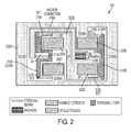
- FIG. 2 shows a single anchor accelerometer in accordance with an embodiment.
- the single anchor comprises an anchor A 210B, two central springs B1 214A and B2 214B, torsional springs 218A, 218B, 218C and 218D, rotational levers 216A and 216B, DOWN electrodes C11 220B and C11 220C, and UP electrodes C21 220A and C21 220D.
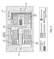
- Figure 3 shows a single lever and single anchor accelerometer 300 in accordance with an embodiment.
- the spring B 314B connects the anchor A 310B to the lever L 316B.
- the two external torsional springs B21 318B and B22 318D connect the end of the lever to the two proof masses PM1 302B and PM2 302A.
- the two proof masses are coupled to the substrate with two translating out-of-plane springs.
- the two translating springs B11 318A and B12 318C must be stiff for rotation around X to have the two proof masses moving in anti-phase direction normal to the plane of the substrate. If those springs are compliant for rotation around the X axis then the sensor 300 rotates around X axis.
- a linear acceleration cause a force on each of the two proof masses PM1 302A ad PM2 302B that is transferred to the lever L 316B and provides a torque on the central spring B 314B.
- the central spring B 314B and the lever L 316B rotate and one of the proof masses moves towards the substrate and the other of the proof masses PM1 302A and PM2 302B moves in the opposite direction.
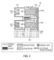
- Figure 4 shows an alternative single lever accelerometer in accordance with an embodiment.
- the single lever comprises proof masses 402A and 402B, anchor 410B, rotational lever 416B, translating springs B11 418A and B12 418C, torsional springs 418B 414B and 418D, DOWN electrodes C1 420A, and UP electrodes C2 420B.
- the translating springs B11 418A and B12 418C must stiff for rotation around the X axis to have the two proof masses moving in anti-phase direction normal to the plane of the substrate.
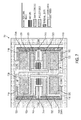
- Figure 5b show the configuration of the sensor to be a capacitive wheatstone bridge in accordance with an embodiment.
- the sensor 500a comprises proof masses 502A and 502B, anchors 510A and 510B, torsional springs 514A, 514B, 518A, 518B, 518C and 518D, rotational levers 516A and 516B, UP electrodes C21 520A, C21 520D, C22 520A and C22 520D, and DOWN electrodes C11 520B, C11 520C, C12 520B and C12 520C.
- the proof masses 502A and 502B moves in an anti-phase direction normal to the substrate increasing the capacitance of capacitors C11 and C12 and decreasing the capacitance of the capacitors C21 and C22.
- the capacitors C11, C21, C12, and C22 can be connected in a Wheatstone bridge configuration as shown in Figure 5b
- Figure 6 shows an accelerometer where a capacitive readout is performed on electrodes on levers instead on proof masses in accordance with an embodiment.
- the sensor comprises proof masses 602A and 602B, rotational levers 616A and 616B, anchors 610A and 610B, torsional springs 614A, 614B, 618A, 618B, 618C, 618D, UP electrodes C21 620A and C21 620D, and DOWN electrodes C11 620B and 620C.
- the electrodes 620A-620D are utilized to detect movement of the rotational levers 616A and 616B.
- FIG. 7 shows an accelerometer including the tilt cancellation paddles in accordance with an embodiment.
- the sensor comprises proof masses 702A and 702B, torsional springs 714A, 714B, 718A, 718B, 718C and 718D, rotational levers 716A and 716B, UP electrodes C21 720A and C21 720D, DOWN electrodes C11 720B and C11 720C, and tilt cancellation paddles 722A and 722B.
- the proof masses 702A and 702B move in anti-phase direction normal to the plane of the substrate with the tilt cancellation paddles 722A and 722B.
- the output induced by a tilt between proof masses and the substrate is canceled by measuring the differential capacitance between tilt cancellation electrodes and UP and DOWN electrodes.
- FIG. 8 shows a combined accelerometer and magnetometer sensor in accordance with an embodiment.
- the combined accelerometer and magnetometer sensor 800 comprises proof masses 802A and 802B, anchors 810A and 810B, torsional springs 814A, 814B, 818A, 818B, 818C and 818D, magnetic materials 816A and 816B, UP electrodes C21 820A and C22 820D, and DOWN electrodes C11 820C and C12 820B.
- the magnetic material induces a torque in response to a magnetic field. This torque will cause the sensor 800 to rotate around x axis.
- acceleration causes the proof masses 802A and 802B to move in anti-phase direction normal to the plane of the substrate.
- the acceleration and magnetic field can be sensed separately because they cause two different sensing modes, respectively the anti-phase movement of the proof masses and the tilting around the first axis.
- the combined accelerometer and magnetometer sensor 800 measures by altering the configuration of a capacitive readout on a circuit shown in Fig. 5b and Fig. 5c .
- the signals are given by: A out ⁇ C 11 + C 12 - C 22 - C 21 M out ⁇ C 11 - C 12 + C 22 - C 21 where A out is the output given by the acceleration and M out is the output given by the magnetic field.
- a cap or a cover provides mechanical protection to a structural layer and optionally forms a portion of an enclosure for the sensor.
- the sensing electrodes can be located in different areas on the sensor.
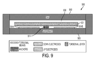
- Figure 9 illustrates a sensor 900 that includes a substrate 906 with a cap 950 coupled thereover with a sensor structure 901 coupled to the substrate by anchor 914 within a cavity 908 of the sensor.
- the UP and DOWN electrodes 904A and 904B are coupled to the substrate 906.
- Figure 10 illustrates a sensor 900' similar to that of Figure 9 except that the UP and DOWN electrodes 904A and 904B are coupled to the cap.
- Figure 11 illustrates a sensor 900" that is also similar to that of Figure 9 except that an UP electrode 904A and a DOWN electrode 904B are on the substrate and there is a DOWN electrode 904C and an UP electrode 904D on the cap 950.
- Figure 12 illustrates a sensor 900'" similar to Figure 9 except that anchor 914 couples the sensor structure 901 to the cap 950 rather that the substrate 906.
- the advantages provided by the anti-phase movement of the proof masses normal to the plane are both a high mechanical sensitivity and a high electrical sensitivity.
- the high mechanical sensitivity is provided because any part of each proof mass is moving by the same amount and so maximizing the inertia that transduces the acceleration in the force causing the proof masses movement.
- the high electrical sensitivity is provided also by the translating movement because the gap between the proof masses and the electrodes will reduce or increase everywhere by the same amount maximizing the capacitance change that is the output signal of the transducer.
- the movement and so the capacitive readout are differential since the proof masses move in anti-phase.
- the high mechanical and electrical sensitivity combined provides a variety of other advantages such as high breakout force, high full scale, high signal to noise ratio, or allow to reduce the size of the sensor by keeping similar performances.
Landscapes
- Physics & Mathematics (AREA)
- General Physics & Mathematics (AREA)
- Pressure Sensors (AREA)
- Engineering & Computer Science (AREA)
- Radar, Positioning & Navigation (AREA)
- Remote Sensing (AREA)
Abstract
Description
- This application claims benefit under 35 USC 119(e) of
U.S. Provisional Patent Application No. 61/920,246, filed on December 23, 2013 - The present invention relates generally to inertial sensors and more particularly to MEMS accelerometers.
- Inertial sensors such as accelerometers are widely used for motion sensing applications. Conventionally, an accelerometer consists of a suspended proof mass and a means of measuring the proof mass displacement with respect to the reference frame. There is always a need to provide improvements in the performance and reliability of an accelerometer for commercial applications. Typically, performance is determined by the mechanical and electrical sensitivities of the sensor and reliability is determined, among many other parameters, by the required breakout force to unstuck moving parts of the structure in case of accidental contact with other fixed or moving parts.
- What is needed therefore is a system and method that provides such inertial sensors. The method and system should be easily implemented, cost effective and adaptable to existing environments. The present invention addresses the above-identified issues.
- A sensor is disclosed. In a first aspect, the sensor includes a substrate and at least two proof masses. The sensor also includes a flexible coupling between the at least two proof masses and the substrate. The at least two coupling proof masses move in an anti-phase direction normal to a plane of the substrate in response to acceleration.
- In a second aspect, a combined accelerometer and a magnetometer includes a substrate and at least two proof masses. The combined accelerometer and the magnetometer also includes a flexible coupling between the two proof masses and the substrate. The proof masses move in an anti-phase direction normal to a plane of the substrate in response to acceleration. The combined accelerometer and the magnetometer also includes a magnetic material that causes the combined accelerometer and magnetometer to rotate around a first axis in response to a magnetic field. The acceleration and magnetic field can be sensed separately because they have two different sensing modes, respectively the anti-phase movement of the proof masses and the tilting around the first axis of the proof masses. For instance outputs of the combined accelerometer and magnetometer can be measured by altering the configuration of transducer to sense separate the outputs given by the acceleration and magnetic field.
-
-
Figure 1 shows an accelerometer that responds to a linear acceleration in a Z direction. -
Figure 2 shows a single anchor accelerometer in accordance with an embodiment. -
Figure 3 shows a single lever and single anchor accelerometer in accordance with an embodiment. -
Figure 4 shows an alternative single lever accelerometer in accordance with an embodiment. -
Figure 5a shows the configuration of the sensor to be a capacitive wheatstone bridge in accordance with an embodiment. -
Figure 5b shows a configuration for sensing acceleration in a Wheatstone bridge configuration as shown in accordance with an embodiment. -
Figure 5c shows a configuration for sensing magnetic field in a Wheatstone bridge configuration as shown in accordance with an embodiment. -
Figure 6 shows an accelerometer where a capacitive readout is performed on a rotational lever instead on proof masses in accordance with an embodiment. -
Figure 7 shows an accelerometer including the tilt cancellation paddles in accordance with an embodiment. -
Figure 8 shows a combined accelerometer and magnetometer sensor in accordance with an embodiment. -
Figures 9-12 show a various embodiments of sensors that includes a cap as part thereof. - The present invention relates generally to inertial sensors and more particularly to MEMS accelerometers. The following description is presented to enable one of ordinary skill in the art to make and use the invention and is provided in the context of a patent application and its requirements. Various modifications to the preferred embodiments and the generic principles and features described herein will be readily apparent to those skilled in the art. Thus, the present invention is not intended to be limited to the embodiments shown, but is to be accorded the widest scope consistent with the principles and features described herein.
- In the described embodiments micro-electro-mechanical systems (MEMS) refers to a class of structures or devices fabricated using semiconductor-like processes and exhibiting mechanical characteristics such as the ability to move or deform. MEMS devices often, but not always, interact with electrical signals. MEMS devices include but are not limited to gyroscopes, accelerometers, magnetometers, pressure sensors, microphones, and radio-frequency components. Silicon wafers containing MEMS structures are referred to as MEMS wafers.
- In the described embodiments, the MEMS device may refer to a semiconductor device implemented as a micro-electro-mechanical system. The MEMS structure may refer to any feature that may be part of a larger MEMS device. The semiconductor layer with the mechanically active MEMS structure is referred to as the device layer. An engineered silicon-on-insulator (ESOI) wafer may refer to a SOI wafer with cavities beneath the silicon device layer or substrate. A handle wafer typically refers to a thicker substrate used as a carrier for the thinner silicon device substrate in a silicon-on-insulator wafer. A handle substrate and a handle wafer can be interchanged.
- In the described embodiments, a cavity may refer to an opening or recession in a substrate wafer and an enclosure may refer to a fully enclosed space. A post may be a vertical structure in the cavity of the MEMS device for mechanical support. A standoff is a vertical structure providing electrical contact.
- In the described embodiments, a rigid structure within a MEMS device that moves when subject to force may be referred to as a plate. Although rigid plates are preferred for the described embodiments, semi rigid plates or deformable membranes could replace rigid plates. Plates may comprise of silicon, silicon containing materials (e.g. poly-silicon, silicon oxide, silicon nitride), metals and materials that are used in semiconductor processes (e.g. aluminum nitride, germanium). A back plate may be a solid or perforated plate comprising at least one electrode. The electrode can be comprised of semiconductor process compatible conductive materials (e.g. poly-silicon, silicon, aluminum, copper, nickel, titanium, chromium, gold). The electrodes may have insulating films on one or more surfaces.
-
Figure 1 shows top and side views of anaccelerometer 100 that responds to a linear acceleration in a Z direction. Theaccelerometer 100 comprises two proof masses PM1 102B and PM2 102A that respond to a linear acceleration in the Z direction by moving in anti-phase direction normal to a plane of asubstrate 106. The anti-phase movement is constrained by a flexible coupling between the twoproof masses PM1 102B andPM2 102A and thesubstrate 106. The flexible coupling comprises two separated anchors A1 110A and A2 110B, two centraltorsional springs B1 114A andB2 114B, tworotational levers L1 116A andL2 116B and four externaltorsional springs B11 118A,B21 118B,B12 118C andB22 118D. The motion of theaccelerometer 100 is measured by an out-of-plane transducer on the proof masses, for instance a set of capacitive differential electrode C1 andC2 120A - 120D. - The
springs B1 114A andB2 114B connect theanchors A1 110A and A2 110B to thelevers L1 116A andL2 116B. The four external torsional springsB11 118A,B21 118B,B12 118C andB22 118D connect the end of one lever to the end of the other lever on the opposite side trough the twoproof masses PM1 102B andPM2 102A. Inparticular spring B11 118A connects the top of theleft lever L1 116A to internalproof mass PM1 102B that connects the bottom of theright lever L2 116B trough thespring B22 118D. In the same way the bottom of theleft lever L1 116A is coupled to the top of theright lever L2 116B with thesprings B12 118C andB22 118D. - For simplicity, suppose that the proof masses have the center of gravity on the axis of the central springs (
B1 114A andB2 114B) and that the external springs (B12 118C,B21 118B,B11 118A andB22 118D) are coupled to the proof masses with the same distance from the center of gravity orthogonal to this axis. A more general case is described in the following. - A linear acceleration a in the Z direction will create a force in Z for each proof mass:


PM1 102B andPM2 102A respectively. On each proof mass half of this force acts on each one of the external springs,B11 118A andB22 118D forPM1 102B andB12 118C andB21 118B forPM2 102A. Finally this force is transferred on the extreme of the lever so in the center of the lever there is a torque that is the difference of this force times the lever ofPM1 102B andPM2 102A:
springs B11 118A toB1 114A andB22 118D toB2 114B and lPM2 is the distance from thesprings B12 118C toB1 114A andB21 118B toB2 114B. The torque M causes the central springs and the two levers to rotate in anti-phase and so one proof mass moves towards the substrate and the other moves in the opposite direction. - In order to cause the anti-phase movement there must be an unbalancing torque M. This unbalanced torque M can be given by a difference in the mass (m1 ≠ m2), by difference in the lever (lPM1 ≠ lPM2), or by a difference in the mass lever product (m1lPM1 ≠ m2lPM2).
- In a more general example, where the center of gravity of the mass is not lying on the spring axis or the external springs are not coupled to proof masses with the same distance orthogonal to this axis, the acceleration cause a torque in addition to the force in the Z direction. In this case the structure of sensor also rotates. The sensor also includes a transducer to measure the motion of the sensor. For instance capacitive sensing can be performed by means of electrodes on the substrate measuring the capacitance change due to the mass motion.
-
Figure 2 shows a single anchor accelerometer in accordance with an embodiment. The single anchor comprises ananchor A 210B, twocentral springs B1 214A andB2 214B, torsional springs 218A, 218B, 218C and 218D,rotational levers DOWN electrodes C11 220B andC11 220C, andUP electrodes C21 220A andC21 220D. In this embodiment as is seen there is only oneanchor A 210B that connects the twocentral springs B1 214A andB2 214B. -
Figure 3 shows a single lever andsingle anchor accelerometer 300 in accordance with an embodiment. - The
spring B 314B connects the anchor A 310B to thelever L 316B. The two external torsional springsB21 318B andB22 318D connect the end of the lever to the twoproof masses PM1 302B andPM2 302A. The two proof masses are coupled to the substrate with two translating out-of-plane springs. - The two translating
springs B11 318A andB12 318C must be stiff for rotation around X to have the two proof masses moving in anti-phase direction normal to the plane of the substrate. If those springs are compliant for rotation around the X axis then thesensor 300 rotates around X axis. - A linear acceleration cause a force on each of the two
proof masses PM1 302A ad PM2 302B that is transferred to thelever L 316B and provides a torque on thecentral spring B 314B. Moreover, if there is an unbalancing in the mass and lever product then thecentral spring B 314B and thelever L 316B rotate and one of the proof masses moves towards the substrate and the other of theproof masses PM1 302A andPM2 302B moves in the opposite direction. -
Figure 4 shows an alternative single lever accelerometer in accordance with an embodiment. The single lever comprisesproof masses anchor 410B,rotational lever 416B, translatingsprings B11 418A andB12 418C, torsional springs418B electrodes C1 420A, andUP electrodes C2 420B. As explained inFigure 3 , the translatingsprings B11 418A andB12 418C must stiff for rotation around the X axis to have the two proof masses moving in anti-phase direction normal to the plane of the substrate. -
Figure 5b show the configuration of the sensor to be a capacitive wheatstone bridge in accordance with an embodiment. Thesensor 500a comprisesproof masses 502A and 502B, anchors 510A and 510B, torsional springs 514A, 514B, 518A, 518B, 518C and 518D,rotational levers UP electrodes C21 520A,C21 520D,C22 520A andC22 520D, andDOWN electrodes C11 520B,C11 520C,C12 520B andC12 520C. In response to acceleration theproof masses 502A and 502B moves in an anti-phase direction normal to the substrate increasing the capacitance of capacitors C11 and C12 and decreasing the capacitance of the capacitors C21 and C22. For sensing acceleration, the capacitors C11, C21, C12, and C22 can be connected in a Wheatstone bridge configuration as shown inFigure 5b -
Figure 6 shows an accelerometer where a capacitive readout is performed on electrodes on levers instead on proof masses in accordance with an embodiment. The sensor comprisesproof masses rotational levers 616A and 616B, anchors 610A and 610B, torsional springs 614A, 614B, 618A, 618B, 618C, 618D,UP electrodes C21 620A andC21 620D, andDOWN electrodes C11 620B and 620C. As is seen, theelectrodes 620A-620D are utilized to detect movement of therotational levers 616A and 616B. -
Figure 7 shows an accelerometer including the tilt cancellation paddles in accordance with an embodiment. The sensor comprisesproof masses rotational levers UP electrodes C21 720A andC21 720D, DOWNelectrodes C11 720B andC11 720C, and tilt cancellation paddles 722A and 722B. Theproof masses -
Figure 8 shows a combined accelerometer and magnetometer sensor in accordance with an embodiment. The combined accelerometer andmagnetometer sensor 800 comprisesproof masses magnetic materials UP electrodes C21 820A andC22 820D, andDOWN electrodes C11 820C and C12 820B. The magnetic material induces a torque in response to a magnetic field. This torque will cause thesensor 800 to rotate around x axis. Moreover, acceleration causes theproof masses - The acceleration and magnetic field can be sensed separately because they cause two different sensing modes, respectively the anti-phase movement of the proof masses and the tilting around the first axis. For instance the combined accelerometer and
magnetometer sensor 800 measures by altering the configuration of a capacitive readout on a circuit shown inFig. 5b and Fig. 5c . In particular the signals are given by:

- A cap or a cover provides mechanical protection to a structural layer and optionally forms a portion of an enclosure for the sensor. When utilizing a cap on top of the substrate the sensing electrodes can be located in different areas on the sensor. To describe this feature in more detail refer now to the following discussion in conjunction with the accompanying Figures.
-
Figure 9 illustrates asensor 900 that includes asubstrate 906 with acap 950 coupled thereover with asensor structure 901 coupled to the substrate byanchor 914 within acavity 908 of the sensor. In this embodiment, the UP andDOWN electrodes substrate 906. -
Figure 10 illustrates a sensor 900' similar to that ofFigure 9 except that the UP andDOWN electrodes Figure 11 illustrates asensor 900" that is also similar to that ofFigure 9 except that anUP electrode 904A and aDOWN electrode 904B are on the substrate and there is aDOWN electrode 904C and anUP electrode 904D on thecap 950.Figure 12 illustrates a sensor 900'" similar toFigure 9 except thatanchor 914 couples thesensor structure 901 to thecap 950 rather that thesubstrate 906. As is readily recognized by one of ordinary skill in the art, for example other embodiments could include on the sensor 900'" electrodes 904 on both thecap 950 and thesubstrate 906 or any combination thereof or one up electrode on the cap and one electrode on the substrate or any combination thereof. - The advantages provided by the anti-phase movement of the proof masses normal to the plane are both a high mechanical sensitivity and a high electrical sensitivity. The high mechanical sensitivity is provided because any part of each proof mass is moving by the same amount and so maximizing the inertia that transduces the acceleration in the force causing the proof masses movement. The high electrical sensitivity is provided also by the translating movement because the gap between the proof masses and the electrodes will reduce or increase everywhere by the same amount maximizing the capacitance change that is the output signal of the transducer. Moreover the movement and so the capacitive readout are differential since the proof masses move in anti-phase.
- The high mechanical and electrical sensitivity combined provides a variety of other advantages such as high breakout force, high full scale, high signal to noise ratio, or allow to reduce the size of the sensor by keeping similar performances.
- Although the present invention has been described in accordance with the embodiments shown, one of ordinary skill in the art will readily recognize that there could be variations to the embodiments and those variations would be within the spirit and scope of the present invention. Accordingly, many modifications may be made by one of ordinary skill in the art without departing from the spirit and scope of the present invention.
Claims (20)
- A sensor comprising:a substrate; anda mechanical structure, where in the mechanical structure includes at least two proof masses including a first and second proof mass, anda flexible coupling between the at least two proof masses and the substrate;wherein the at least two proof masses move in an anti-phase direction normal to a plane of the substrate in response to acceleration of the sensor.
- The sensor of claim 1, wherein the first and second proof masses are of different weights.
- The sensor of claim 1, wherein the flexible coupling further comprises:at least one anchor; anda torsional system; the torsional system further including an anchoring spring connecting the at least one anchor and a first rotational lever;a first torsional spring connects the first proof mass to the rotational lever with a first lever length; and a second torsional spring connects the second proof mass to the first rotational lever with a second lever length.
- The sensor of claim 3, wherein the first lever length and the second lever length of the first rotational lever are different.
- The sensor of claim 4, wherein the flexible coupling further includes a second anchoring spring connecting the at least one anchor and a second rotational lever;
a third torsional spring connects the first proof mass to the second rotational lever with a third lever length; and a fourth torsional spring connects the second proof mass to the second rotational lever with a fourth lever length;
wherein the second rotational lever rotates counter to the rotation of the first rotational lever in response to acceleration of the sensor. - The sensor of claim 5, wherein the third lever length and the fourth lever length of the second rotational lever are different.
- The sensor of claim 5, further comprising magnetic material, wherein the magnetic material is on any of the at least two proof masses, on the first rotational lever, and the second rotational levers.
- The sensor of claim 3, further comprising a translational system wherein the translational system includes a first translating spring connecting the at least one anchor to the first proof mass and a second translating spring connecting the at least one anchor to the second proof mass, wherein the first and second translating springs allow motion of the first and second proof masses in a direction normal to the plane of the substrate.
- The sensor of claim 8, wherein each translating spring comprises a second rotational lever and at least two rotating spring; wherein one of the rotating springs are coupled to the proof mass and other connected to the anchor.
- The sensor of claim 1, further comprising a transducer for measuring motion of the mechanical structure relative to the substrate.
- The sensor of claim 10, wherein the motion of the at least two proof masses relative to the substrate is measured by the transducer via capacitive sensing.
- The sensor of claim 1, wherein motion of the at least two proof masses relative to each other are measured by a transducer.
- The sensor of claim 12, where in the transducer is a capacitive sensor.
- The sensor of claim 10, wherein the displacement of the coupling springs are measured by the transducer via capacitive sensing.
- The sensor of claim 3, wherein a displacement of the first rotational lever is measured by the transducer via capacitive sensing.
- The sensor of claim 11, wherein the one or more electrodes are located on the substrate.
- The sensor of claim 11, further comprising a cap, wherein the mechanical structure is located between the cap and the substrate, wherein the one or more electrodes are located on the cap facing the mechanical structure.
- A sensor comprising:a substrate; anda mechanical structure, where in the mechanical structure includes at least two proof masses,a flexible coupling between the at least two proof masses and the substrate,a magnetic material;wherein the mechanical structure rotates around a first axis in response to a magnetic field;wherein the at least two proof masses move in an anti-phase direction normal to a plane of the substrate in response to acceleration of the sensor.
- The sensor of claim 18, further comprising a transducer to measure out-of-plane motion of the mechanical structure; and
wherein motion due acceleration and motion induced by magnetic field are measured by the transducer. - The sensor of claim 18, further comprises a signal processor to alter configuration of the transducer to switch between measuring motion due to acceleration and motion induced by magnetic field.
Applications Claiming Priority (2)
| Application Number | Priority Date | Filing Date | Title |
|---|---|---|---|
| US201361920246P | 2013-12-23 | 2013-12-23 | |
| US14/188,173 US8973439B1 (en) | 2013-12-23 | 2014-02-24 | MEMS accelerometer with proof masses moving in anti-phase direction normal to the plane of the substrate |
Publications (2)
| Publication Number | Publication Date |
|---|---|
| EP2887073A1 true EP2887073A1 (en) | 2015-06-24 |
| EP2887073B1 EP2887073B1 (en) | 2017-04-26 |
Family
ID=52597709
Family Applications (1)
| Application Number | Title | Priority Date | Filing Date |
|---|---|---|---|
| EP14199883.1A Active EP2887073B1 (en) | 2013-12-23 | 2014-12-22 | MEMS accelerometer with proof masses moving in anti-phase direction normal to the plane of the substrate |
Country Status (4)
| Country | Link |
|---|---|
| US (1) | US8973439B1 (en) |
| EP (1) | EP2887073B1 (en) |
| KR (1) | KR101697828B1 (en) |
| CN (1) | CN104730289B (en) |
Cited By (2)
| Publication number | Priority date | Publication date | Assignee | Title |
|---|---|---|---|---|
| EP3382400A1 (en) * | 2017-03-27 | 2018-10-03 | NXP USA, Inc. | Three-axis inertial sensor for detecting linear acceleration |
| US10809277B2 (en) | 2017-12-18 | 2020-10-20 | Nxp Usa, Inc. | Single axis inertial sensor with suppressed parasitic modes |
Families Citing this family (17)
| Publication number | Priority date | Publication date | Assignee | Title |
|---|---|---|---|---|
| US9606191B2 (en) * | 2013-03-15 | 2017-03-28 | Invensense, Inc. | Magnetometer using magnetic materials on accelerometer |
| US9840409B2 (en) * | 2015-01-28 | 2017-12-12 | Invensense, Inc. | Translating Z axis accelerometer |
| US9720012B2 (en) * | 2015-07-21 | 2017-08-01 | Nxp Usa, Inc. | Multi-axis inertial sensor with dual mass and integrated damping structure |
| DE102015117094B4 (en) * | 2015-10-07 | 2020-04-23 | Tdk Electronics Ag | MEMS rotation rate sensor |
| DE102017130384B4 (en) * | 2016-12-19 | 2022-03-31 | Analog Devices, Inc. | Synchronized mass gyroscope |
| US10466053B2 (en) * | 2017-04-04 | 2019-11-05 | Invensense, Inc. | Out-of-plane sensing gyroscope robust to external acceleration and rotation |
| US10759656B2 (en) | 2017-09-29 | 2020-09-01 | Apple Inc. | MEMS sensor with dual pendulous proof masses |
| US10732199B2 (en) | 2017-12-20 | 2020-08-04 | Apple Inc. | Multi-stage MEMS accelerometer for mixed g-level operation |
| US11009350B2 (en) | 2018-01-11 | 2021-05-18 | Invensense, Inc. | Proof mass offset compensation |
| CN108020687B (en) * | 2018-02-06 | 2024-03-19 | 深迪半导体(绍兴)有限公司 | MEMS accelerometer |
| US10866258B2 (en) | 2018-07-20 | 2020-12-15 | Honeywell International Inc. | In-plane translational vibrating beam accelerometer with mechanical isolation and 4-fold symmetry |
| RU192953U1 (en) * | 2018-12-20 | 2019-10-08 | федеральное государственное автономное образовательное учреждение высшего образования "Санкт-Петербургский национальный исследовательский университет информационных технологий, механики и оптики" (Университет ИТМО) | MEMS ACCELEROMETER |
| US11307218B2 (en) * | 2020-05-22 | 2022-04-19 | Invensense, Inc. | Real-time isolation of self-test and linear acceleration signals |
| CN111721970B (en) * | 2020-06-16 | 2022-03-18 | 维沃移动通信有限公司 | Capacitive acceleration sensor and its control method, control device and electronic device |
| DE102020212998A1 (en) * | 2020-10-15 | 2022-04-21 | Robert Bosch Gesellschaft mit beschränkter Haftung | Micromechanical z-inertial sensor |
| CN116601500A (en) | 2020-12-18 | 2023-08-15 | 美国亚德诺半导体公司 | Accelerometer with translational motion of mass |
| EP4116718B1 (en) * | 2021-07-05 | 2026-01-28 | Murata Manufacturing Co., Ltd. | Seesaw accelerometer |
Citations (3)
| Publication number | Priority date | Publication date | Assignee | Title |
|---|---|---|---|---|
| EP2315039A1 (en) * | 2008-07-04 | 2011-04-27 | Alps Electric Co., Ltd. | Capacitance detection type movable sensor |
| EP2343556A1 (en) * | 2009-12-22 | 2011-07-13 | Commissariat à l'Énergie Atomique et aux Énergies Alternatives | Micromechanical structure including a mobile part equipped with stops for out-of-plane movements of the structure, and the method for making said structure |
| WO2013115967A1 (en) * | 2012-02-01 | 2013-08-08 | Fairchild Semiconductor Corporation | Mems proof mass with split z-axis portions |
Family Cites Families (12)
| Publication number | Priority date | Publication date | Assignee | Title |
|---|---|---|---|---|
| JPH05215627A (en) * | 1992-02-04 | 1993-08-24 | Kazuhiro Okada | Device for detecting force, acceleration, and magnetism in multidimensional direction |
| US6230563B1 (en) * | 1998-06-09 | 2001-05-15 | Integrated Micro Instruments, Inc. | Dual-mass vibratory rate gyroscope with suppressed translational acceleration response and quadrature-error correction capability |
| US20060169041A1 (en) * | 2005-02-02 | 2006-08-03 | Madni Asad M | Combined gyroscope and 2-axis accelerometer |
| JP5125327B2 (en) * | 2006-11-09 | 2013-01-23 | 三菱電機株式会社 | Acceleration sensor |
| US7971483B2 (en) * | 2008-03-28 | 2011-07-05 | Honeywell International Inc. | Systems and methods for acceleration and rotational determination from an out-of-plane MEMS device |
| US8186221B2 (en) * | 2009-03-24 | 2012-05-29 | Freescale Semiconductor, Inc. | Vertically integrated MEMS acceleration transducer |
| JP5223003B2 (en) * | 2009-06-03 | 2013-06-26 | アルプス電気株式会社 | Physical quantity sensor |
| US8307710B2 (en) * | 2009-07-09 | 2012-11-13 | Honeywell International Inc. | Translational mass in-plane MEMS accelerometer |
| ITTO20090973A1 (en) * | 2009-12-10 | 2011-06-11 | St Microelectronics Srl | TRIASSIAL INTEGRATED MAGNETOMETER OF SEMICONDUCTOR MATERIAL MADE IN MEMS TECHNOLOGY |
| US8539836B2 (en) * | 2011-01-24 | 2013-09-24 | Freescale Semiconductor, Inc. | MEMS sensor with dual proof masses |
| TWI452297B (en) * | 2011-09-26 | 2014-09-11 | Richwave Technology Corp | Capacitive accelerometer |
| JP5898571B2 (en) * | 2012-05-31 | 2016-04-06 | アルプス電気株式会社 | MEMS sensor |
-
2014
- 2014-02-24 US US14/188,173 patent/US8973439B1/en active Active
- 2014-12-19 CN CN201410798641.6A patent/CN104730289B/en active Active
- 2014-12-19 KR KR1020140183771A patent/KR101697828B1/en active Active
- 2014-12-22 EP EP14199883.1A patent/EP2887073B1/en active Active
Patent Citations (3)
| Publication number | Priority date | Publication date | Assignee | Title |
|---|---|---|---|---|
| EP2315039A1 (en) * | 2008-07-04 | 2011-04-27 | Alps Electric Co., Ltd. | Capacitance detection type movable sensor |
| EP2343556A1 (en) * | 2009-12-22 | 2011-07-13 | Commissariat à l'Énergie Atomique et aux Énergies Alternatives | Micromechanical structure including a mobile part equipped with stops for out-of-plane movements of the structure, and the method for making said structure |
| WO2013115967A1 (en) * | 2012-02-01 | 2013-08-08 | Fairchild Semiconductor Corporation | Mems proof mass with split z-axis portions |
Cited By (3)
| Publication number | Priority date | Publication date | Assignee | Title |
|---|---|---|---|---|
| EP3382400A1 (en) * | 2017-03-27 | 2018-10-03 | NXP USA, Inc. | Three-axis inertial sensor for detecting linear acceleration |
| US10429407B2 (en) | 2017-03-27 | 2019-10-01 | Nxp Usa, Inc. | Three-axis inertial sensor for detecting linear acceleration forces |
| US10809277B2 (en) | 2017-12-18 | 2020-10-20 | Nxp Usa, Inc. | Single axis inertial sensor with suppressed parasitic modes |
Also Published As
| Publication number | Publication date |
|---|---|
| EP2887073B1 (en) | 2017-04-26 |
| US8973439B1 (en) | 2015-03-10 |
| KR20150073856A (en) | 2015-07-01 |
| KR101697828B1 (en) | 2017-02-01 |
| CN104730289B (en) | 2018-10-26 |
| CN104730289A (en) | 2015-06-24 |
Similar Documents
| Publication | Publication Date | Title |
|---|---|---|
| EP2887073B1 (en) | MEMS accelerometer with proof masses moving in anti-phase direction normal to the plane of the substrate | |
| US10371715B2 (en) | MEMS accelerometer with proof masses moving in an anti-phase direction | |
| EP2328833B1 (en) | Mems sensor with movable z-axis sensing element | |
| CN102597699B (en) | Micromachined inertial sensor devices | |
| CN102590555B (en) | Resonance-force balance capacitive three-axis acceleration sensor and manufacturing method | |
| US8100012B2 (en) | MEMS sensor with cap electrode | |
| CN107576322B (en) | Micro-Electro-Mechanical Systems (MEMS) proof-mass with separate z-axis sections | |
| US8322216B2 (en) | Micromachined accelerometer with monolithic electrodes and method of making the same | |
| US8939029B2 (en) | MEMS sensor with movable Z-axis sensing element | |
| US7814794B2 (en) | Micromachined sensors | |
| EP2284545B1 (en) | Coplanar proofmasses employable to sense acceleration along three axes | |
| US10137851B2 (en) | MEMS sensor and a semiconductor package | |
| CN102180435A (en) | Integrated micro electro-mechanical system (MEMS) device and forming method thereof | |
| US20160370403A1 (en) | Capacitive accelerometer devices and wafer level vacuum encapsulation methods | |
| GB2579057A (en) | Accelerometer | |
| US12259403B2 (en) | Inertial sensor module | |
| CN105182005B (en) | A kind of accelerometer | |
| EP4220191A1 (en) | Accelerometer, inertial measurement unit (imu) and electronic device | |
| CN102408089A (en) | Micro-electromechanical sensor capable of measuring acceleration and pressure simultaneously | |
| Tay et al. | A differential capacitive low-g microaccelerometer with mg resolution | |
| US10241129B1 (en) | MEMS piston-tube based capacitive accelerometer | |
| US20070193380A1 (en) | Z offset MEMS device | |
| JP6301268B2 (en) | MEMS sensor with movable z-axis sensing element | |
| CN121027562A (en) | accelerometer |
Legal Events
| Date | Code | Title | Description |
|---|---|---|---|
| PUAI | Public reference made under article 153(3) epc to a published international application that has entered the european phase |
Free format text: ORIGINAL CODE: 0009012 |
|
| 17P | Request for examination filed |
Effective date: 20141222 |
|
| AK | Designated contracting states |
Kind code of ref document: A1 Designated state(s): AL AT BE BG CH CY CZ DE DK EE ES FI FR GB GR HR HU IE IS IT LI LT LU LV MC MK MT NL NO PL PT RO RS SE SI SK SM TR |
|
| AX | Request for extension of the european patent |
Extension state: BA ME |
|
| R17P | Request for examination filed (corrected) |
Effective date: 20151223 |
|
| RBV | Designated contracting states (corrected) |
Designated state(s): AL AT BE BG CH CY CZ DE DK EE ES FI FR GB GR HR HU IE IS IT LI LT LU LV MC MK MT NL NO PL PT RO RS SE SI SK SM TR |
|
| RIN1 | Information on inventor provided before grant (corrected) |
Inventor name: BALDASARRE, LEONARDO Inventor name: THOMPSON, MATTHEW JULIAN |
|
| 17Q | First examination report despatched |
Effective date: 20160129 |
|
| GRAP | Despatch of communication of intention to grant a patent |
Free format text: ORIGINAL CODE: EPIDOSNIGR1 |
|
| INTG | Intention to grant announced |
Effective date: 20161115 |
|
| GRAS | Grant fee paid |
Free format text: ORIGINAL CODE: EPIDOSNIGR3 |
|
| GRAA | (expected) grant |
Free format text: ORIGINAL CODE: 0009210 |
|
| AK | Designated contracting states |
Kind code of ref document: B1 Designated state(s): AL AT BE BG CH CY CZ DE DK EE ES FI FR GB GR HR HU IE IS IT LI LT LU LV MC MK MT NL NO PL PT RO RS SE SI SK SM TR |
|
| REG | Reference to a national code |
Ref country code: GB Ref legal event code: FG4D |
|
| REG | Reference to a national code |
Ref country code: CH Ref legal event code: EP |
|
| REG | Reference to a national code |
Ref country code: AT Ref legal event code: REF Ref document number: 888335 Country of ref document: AT Kind code of ref document: T Effective date: 20170515 |
|
| REG | Reference to a national code |
Ref country code: IE Ref legal event code: FG4D |
|
| REG | Reference to a national code |
Ref country code: DE Ref legal event code: R096 Ref document number: 602014009004 Country of ref document: DE |
|
| REG | Reference to a national code |
Ref country code: NL Ref legal event code: MP Effective date: 20170426 |
|
| REG | Reference to a national code |
Ref country code: LT Ref legal event code: MG4D |
|
| REG | Reference to a national code |
Ref country code: AT Ref legal event code: MK05 Ref document number: 888335 Country of ref document: AT Kind code of ref document: T Effective date: 20170426 |
|
| PG25 | Lapsed in a contracting state [announced via postgrant information from national office to epo] |
Ref country code: NL Free format text: LAPSE BECAUSE OF FAILURE TO SUBMIT A TRANSLATION OF THE DESCRIPTION OR TO PAY THE FEE WITHIN THE PRESCRIBED TIME-LIMIT Effective date: 20170426 |
|
| PG25 | Lapsed in a contracting state [announced via postgrant information from national office to epo] |
Ref country code: LT Free format text: LAPSE BECAUSE OF FAILURE TO SUBMIT A TRANSLATION OF THE DESCRIPTION OR TO PAY THE FEE WITHIN THE PRESCRIBED TIME-LIMIT Effective date: 20170426 Ref country code: AT Free format text: LAPSE BECAUSE OF FAILURE TO SUBMIT A TRANSLATION OF THE DESCRIPTION OR TO PAY THE FEE WITHIN THE PRESCRIBED TIME-LIMIT Effective date: 20170426 Ref country code: NO Free format text: LAPSE BECAUSE OF FAILURE TO SUBMIT A TRANSLATION OF THE DESCRIPTION OR TO PAY THE FEE WITHIN THE PRESCRIBED TIME-LIMIT Effective date: 20170726 Ref country code: ES Free format text: LAPSE BECAUSE OF FAILURE TO SUBMIT A TRANSLATION OF THE DESCRIPTION OR TO PAY THE FEE WITHIN THE PRESCRIBED TIME-LIMIT Effective date: 20170426 Ref country code: GR Free format text: LAPSE BECAUSE OF FAILURE TO SUBMIT A TRANSLATION OF THE DESCRIPTION OR TO PAY THE FEE WITHIN THE PRESCRIBED TIME-LIMIT Effective date: 20170727 Ref country code: FI Free format text: LAPSE BECAUSE OF FAILURE TO SUBMIT A TRANSLATION OF THE DESCRIPTION OR TO PAY THE FEE WITHIN THE PRESCRIBED TIME-LIMIT Effective date: 20170426 Ref country code: HR Free format text: LAPSE BECAUSE OF FAILURE TO SUBMIT A TRANSLATION OF THE DESCRIPTION OR TO PAY THE FEE WITHIN THE PRESCRIBED TIME-LIMIT Effective date: 20170426 |
|
| REG | Reference to a national code |
Ref country code: FR Ref legal event code: PLFP Year of fee payment: 4 |
|
| PG25 | Lapsed in a contracting state [announced via postgrant information from national office to epo] |
Ref country code: RS Free format text: LAPSE BECAUSE OF FAILURE TO SUBMIT A TRANSLATION OF THE DESCRIPTION OR TO PAY THE FEE WITHIN THE PRESCRIBED TIME-LIMIT Effective date: 20170426 Ref country code: IS Free format text: LAPSE BECAUSE OF FAILURE TO SUBMIT A TRANSLATION OF THE DESCRIPTION OR TO PAY THE FEE WITHIN THE PRESCRIBED TIME-LIMIT Effective date: 20170826 Ref country code: BG Free format text: LAPSE BECAUSE OF FAILURE TO SUBMIT A TRANSLATION OF THE DESCRIPTION OR TO PAY THE FEE WITHIN THE PRESCRIBED TIME-LIMIT Effective date: 20170726 Ref country code: SE Free format text: LAPSE BECAUSE OF FAILURE TO SUBMIT A TRANSLATION OF THE DESCRIPTION OR TO PAY THE FEE WITHIN THE PRESCRIBED TIME-LIMIT Effective date: 20170426 Ref country code: LV Free format text: LAPSE BECAUSE OF FAILURE TO SUBMIT A TRANSLATION OF THE DESCRIPTION OR TO PAY THE FEE WITHIN THE PRESCRIBED TIME-LIMIT Effective date: 20170426 Ref country code: PL Free format text: LAPSE BECAUSE OF FAILURE TO SUBMIT A TRANSLATION OF THE DESCRIPTION OR TO PAY THE FEE WITHIN THE PRESCRIBED TIME-LIMIT Effective date: 20170426 |
|
| REG | Reference to a national code |
Ref country code: DE Ref legal event code: R097 Ref document number: 602014009004 Country of ref document: DE |
|
| PG25 | Lapsed in a contracting state [announced via postgrant information from national office to epo] |
Ref country code: RO Free format text: LAPSE BECAUSE OF FAILURE TO SUBMIT A TRANSLATION OF THE DESCRIPTION OR TO PAY THE FEE WITHIN THE PRESCRIBED TIME-LIMIT Effective date: 20170426 Ref country code: CZ Free format text: LAPSE BECAUSE OF FAILURE TO SUBMIT A TRANSLATION OF THE DESCRIPTION OR TO PAY THE FEE WITHIN THE PRESCRIBED TIME-LIMIT Effective date: 20170426 Ref country code: SK Free format text: LAPSE BECAUSE OF FAILURE TO SUBMIT A TRANSLATION OF THE DESCRIPTION OR TO PAY THE FEE WITHIN THE PRESCRIBED TIME-LIMIT Effective date: 20170426 Ref country code: DK Free format text: LAPSE BECAUSE OF FAILURE TO SUBMIT A TRANSLATION OF THE DESCRIPTION OR TO PAY THE FEE WITHIN THE PRESCRIBED TIME-LIMIT Effective date: 20170426 Ref country code: EE Free format text: LAPSE BECAUSE OF FAILURE TO SUBMIT A TRANSLATION OF THE DESCRIPTION OR TO PAY THE FEE WITHIN THE PRESCRIBED TIME-LIMIT Effective date: 20170426 |
|
| PG25 | Lapsed in a contracting state [announced via postgrant information from national office to epo] |
Ref country code: SM Free format text: LAPSE BECAUSE OF FAILURE TO SUBMIT A TRANSLATION OF THE DESCRIPTION OR TO PAY THE FEE WITHIN THE PRESCRIBED TIME-LIMIT Effective date: 20170426 |
|
| PLBE | No opposition filed within time limit |
Free format text: ORIGINAL CODE: 0009261 |
|
| STAA | Information on the status of an ep patent application or granted ep patent |
Free format text: STATUS: NO OPPOSITION FILED WITHIN TIME LIMIT |
|
| 26N | No opposition filed |
Effective date: 20180129 |
|
| PG25 | Lapsed in a contracting state [announced via postgrant information from national office to epo] |
Ref country code: SI Free format text: LAPSE BECAUSE OF FAILURE TO SUBMIT A TRANSLATION OF THE DESCRIPTION OR TO PAY THE FEE WITHIN THE PRESCRIBED TIME-LIMIT Effective date: 20170426 |
|
| REG | Reference to a national code |
Ref country code: CH Ref legal event code: PL |
|
| REG | Reference to a national code |
Ref country code: IE Ref legal event code: MM4A |
|
| PG25 | Lapsed in a contracting state [announced via postgrant information from national office to epo] |
Ref country code: MT Free format text: LAPSE BECAUSE OF NON-PAYMENT OF DUE FEES Effective date: 20171222 Ref country code: LU Free format text: LAPSE BECAUSE OF NON-PAYMENT OF DUE FEES Effective date: 20171222 |
|
| REG | Reference to a national code |
Ref country code: BE Ref legal event code: MM Effective date: 20171231 |
|
| PG25 | Lapsed in a contracting state [announced via postgrant information from national office to epo] |
Ref country code: IE Free format text: LAPSE BECAUSE OF NON-PAYMENT OF DUE FEES Effective date: 20171222 |
|
| PG25 | Lapsed in a contracting state [announced via postgrant information from national office to epo] |
Ref country code: CH Free format text: LAPSE BECAUSE OF NON-PAYMENT OF DUE FEES Effective date: 20171231 Ref country code: LI Free format text: LAPSE BECAUSE OF NON-PAYMENT OF DUE FEES Effective date: 20171231 Ref country code: BE Free format text: LAPSE BECAUSE OF NON-PAYMENT OF DUE FEES Effective date: 20171231 |
|
| PG25 | Lapsed in a contracting state [announced via postgrant information from national office to epo] |
Ref country code: MC Free format text: LAPSE BECAUSE OF FAILURE TO SUBMIT A TRANSLATION OF THE DESCRIPTION OR TO PAY THE FEE WITHIN THE PRESCRIBED TIME-LIMIT Effective date: 20170426 Ref country code: HU Free format text: LAPSE BECAUSE OF FAILURE TO SUBMIT A TRANSLATION OF THE DESCRIPTION OR TO PAY THE FEE WITHIN THE PRESCRIBED TIME-LIMIT; INVALID AB INITIO Effective date: 20141222 |
|
| GBPC | Gb: european patent ceased through non-payment of renewal fee |
Effective date: 20181222 |
|
| PG25 | Lapsed in a contracting state [announced via postgrant information from national office to epo] |
Ref country code: CY Free format text: LAPSE BECAUSE OF FAILURE TO SUBMIT A TRANSLATION OF THE DESCRIPTION OR TO PAY THE FEE WITHIN THE PRESCRIBED TIME-LIMIT Effective date: 20170426 |
|
| PG25 | Lapsed in a contracting state [announced via postgrant information from national office to epo] |
Ref country code: MK Free format text: LAPSE BECAUSE OF FAILURE TO SUBMIT A TRANSLATION OF THE DESCRIPTION OR TO PAY THE FEE WITHIN THE PRESCRIBED TIME-LIMIT Effective date: 20170426 |
|
| PG25 | Lapsed in a contracting state [announced via postgrant information from national office to epo] |
Ref country code: GB Free format text: LAPSE BECAUSE OF NON-PAYMENT OF DUE FEES Effective date: 20181222 |
|
| PG25 | Lapsed in a contracting state [announced via postgrant information from national office to epo] |
Ref country code: TR Free format text: LAPSE BECAUSE OF FAILURE TO SUBMIT A TRANSLATION OF THE DESCRIPTION OR TO PAY THE FEE WITHIN THE PRESCRIBED TIME-LIMIT Effective date: 20170426 |
|
| PG25 | Lapsed in a contracting state [announced via postgrant information from national office to epo] |
Ref country code: PT Free format text: LAPSE BECAUSE OF FAILURE TO SUBMIT A TRANSLATION OF THE DESCRIPTION OR TO PAY THE FEE WITHIN THE PRESCRIBED TIME-LIMIT Effective date: 20170426 |
|
| PG25 | Lapsed in a contracting state [announced via postgrant information from national office to epo] |
Ref country code: AL Free format text: LAPSE BECAUSE OF FAILURE TO SUBMIT A TRANSLATION OF THE DESCRIPTION OR TO PAY THE FEE WITHIN THE PRESCRIBED TIME-LIMIT Effective date: 20170426 |
|
| P01 | Opt-out of the competence of the unified patent court (upc) registered |
Effective date: 20230524 |
|
| PGFP | Annual fee paid to national office [announced via postgrant information from national office to epo] |
Ref country code: DE Payment date: 20250930 Year of fee payment: 12 |
|
| PGFP | Annual fee paid to national office [announced via postgrant information from national office to epo] |
Ref country code: IT Payment date: 20251121 Year of fee payment: 12 |
|
| PGFP | Annual fee paid to national office [announced via postgrant information from national office to epo] |
Ref country code: FR Payment date: 20251110 Year of fee payment: 12 |