EP2887007B1 - Setting device for monitoring components - Google Patents
Setting device for monitoring components Download PDFInfo
- Publication number
- EP2887007B1 EP2887007B1 EP13198642.4A EP13198642A EP2887007B1 EP 2887007 B1 EP2887007 B1 EP 2887007B1 EP 13198642 A EP13198642 A EP 13198642A EP 2887007 B1 EP2887007 B1 EP 2887007B1
- Authority
- EP
- European Patent Office
- Prior art keywords
- support device
- support
- field
- instrument
- curved surface
- Prior art date
- Legal status (The legal status is an assumption and is not a legal conclusion. Google has not performed a legal analysis and makes no representation as to the accuracy of the status listed.)
- Active
Links
- 238000012544 monitoring process Methods 0.000 title 1
- 230000005291 magnetic effect Effects 0.000 claims description 32
- 230000004907 flux Effects 0.000 claims description 19
- 230000000295 complement effect Effects 0.000 claims description 12
- 239000000463 material Substances 0.000 claims description 10
- 230000003287 optical effect Effects 0.000 claims description 7
- 230000035699 permeability Effects 0.000 claims description 6
- 239000003990 capacitor Substances 0.000 claims description 5
- 229910010293 ceramic material Inorganic materials 0.000 claims description 3
- 239000010432 diamond Substances 0.000 claims description 3
- 229910003460 diamond Inorganic materials 0.000 claims description 3
- 229910052761 rare earth metal Inorganic materials 0.000 claims description 3
- 150000002910 rare earth metals Chemical group 0.000 claims description 3
- 229910000831 Steel Inorganic materials 0.000 claims description 2
- 239000010959 steel Substances 0.000 claims description 2
- 238000005259 measurement Methods 0.000 description 15
- 230000005684 electric field Effects 0.000 description 14
- 230000007246 mechanism Effects 0.000 description 6
- 210000000056 organ Anatomy 0.000 description 6
- 230000007547 defect Effects 0.000 description 4
- 238000005229 chemical vapour deposition Methods 0.000 description 2
- 238000010276 construction Methods 0.000 description 2
- 239000010431 corundum Substances 0.000 description 2
- 229910052593 corundum Inorganic materials 0.000 description 2
- 239000010437 gem Substances 0.000 description 2
- 238000000034 method Methods 0.000 description 2
- 229910001209 Low-carbon steel Inorganic materials 0.000 description 1
- 230000004308 accommodation Effects 0.000 description 1
- 239000012141 concentrate Substances 0.000 description 1
- 239000004020 conductor Substances 0.000 description 1
- 230000001419 dependent effect Effects 0.000 description 1
- 238000000151 deposition Methods 0.000 description 1
- 238000005516 engineering process Methods 0.000 description 1
- 230000004438 eyesight Effects 0.000 description 1
- 230000005294 ferromagnetic effect Effects 0.000 description 1
- 229910001751 gemstone Inorganic materials 0.000 description 1
- PCHJSUWPFVWCPO-UHFFFAOYSA-N gold Chemical compound [Au] PCHJSUWPFVWCPO-UHFFFAOYSA-N 0.000 description 1
- 239000010931 gold Substances 0.000 description 1
- 229910052737 gold Inorganic materials 0.000 description 1
- 238000003384 imaging method Methods 0.000 description 1
- 230000006698 induction Effects 0.000 description 1
- 230000001939 inductive effect Effects 0.000 description 1
- 238000007689 inspection Methods 0.000 description 1
- 238000009434 installation Methods 0.000 description 1
- 239000000696 magnetic material Substances 0.000 description 1
- 238000012423 maintenance Methods 0.000 description 1
- 238000000691 measurement method Methods 0.000 description 1
- 230000010287 polarization Effects 0.000 description 1
- 210000003625 skull Anatomy 0.000 description 1
- 239000007787 solid Substances 0.000 description 1
- 238000001228 spectrum Methods 0.000 description 1
- 230000003068 static effect Effects 0.000 description 1
- 238000012360 testing method Methods 0.000 description 1
- 238000002604 ultrasonography Methods 0.000 description 1
- 238000012795 verification Methods 0.000 description 1
Images


Classifications
-
- G—PHYSICS
- G01—MEASURING; TESTING
- G01B—MEASURING LENGTH, THICKNESS OR SIMILAR LINEAR DIMENSIONS; MEASURING ANGLES; MEASURING AREAS; MEASURING IRREGULARITIES OF SURFACES OR CONTOURS
- G01B7/00—Measuring arrangements characterised by the use of electric or magnetic techniques
- G01B7/30—Measuring arrangements characterised by the use of electric or magnetic techniques for measuring angles or tapers; for testing the alignment of axes
- G01B7/31—Measuring arrangements characterised by the use of electric or magnetic techniques for measuring angles or tapers; for testing the alignment of axes for testing the alignment of axes
-
- G—PHYSICS
- G04—HOROLOGY
- G04B—MECHANICALLY-DRIVEN CLOCKS OR WATCHES; MECHANICAL PARTS OF CLOCKS OR WATCHES IN GENERAL; TIME PIECES USING THE POSITION OF THE SUN, MOON OR STARS
- G04B31/00—Bearings; Point suspensions or counter-point suspensions; Pivot bearings; Single parts therefor
-
- F—MECHANICAL ENGINEERING; LIGHTING; HEATING; WEAPONS; BLASTING
- F16—ENGINEERING ELEMENTS AND UNITS; GENERAL MEASURES FOR PRODUCING AND MAINTAINING EFFECTIVE FUNCTIONING OF MACHINES OR INSTALLATIONS; THERMAL INSULATION IN GENERAL
- F16C—SHAFTS; FLEXIBLE SHAFTS; ELEMENTS OR CRANKSHAFT MECHANISMS; ROTARY BODIES OTHER THAN GEARING ELEMENTS; BEARINGS
- F16C32/00—Bearings not otherwise provided for
- F16C32/04—Bearings not otherwise provided for using magnetic or electric supporting means
- F16C32/0406—Magnetic bearings
- F16C32/0408—Passive magnetic bearings
Definitions
- the present invention relates to a setting device for measuring or controlling small components, in particular for centering a rotating or rotating mobile component.
- a particular field of application of the invention relates to measuring or controlling components of watch mechanisms.
- Vision control methods would allow a measurement of several geometries to be controlled, but the difficulty of these methods is to ensure that the holding in position of the parts does not mask the surfaces to be controlled. Moreover, for the setting of the rotating watch parts, it must be ensured that the axis of rotation is kept continuously in equilibrium, without any noticeable vibration, during the test of rotation of the part.
- the document GB 739979 describes a magnetic bearing for a rotary member of an electrical sensor whose axis is held between two permanent magnets.
- US 4,340,038 discloses a device for transferring energy from an external device to a device implanted in the skull using a magnetic flux concentrator element.
- An object of the invention is to provide a setting device for the control or the measurement of small components, at the scale millimeter or less, which is accurate, reliable, and economical to implement.
- a particular object of the invention is to provide a setting device for the control or measurement by an apparatus for viewing components of small size, which is accurate, reliable, and economical to implement.
- a particular object of the invention is to provide a setting device for the control or measurement by an apparatus for viewing components of watch mechanisms, which is accurate, reliable, and economical to implement.
- a particular object of the invention is to provide a measuring and control device comprising a setting device for the control or measurement by an apparatus for viewing small components such as components of watch mechanisms, which is accurate reliable and economical to implement.
- a setting device comprising a support comprising a body, a working surface disposed on one side of the support, a field concentration element mounted in a housing of the support, and a magnetic and / or electric field generator.
- the field concentration element comprises a base portion and a field concentration portion disposed proximate the work surface, the base portion including an axial base surface having an average width or diameter D2 at its larger periphery. a diameter D1 of the flux concentration part at an axial end surface.
- the base portion is connected to the flux concentration portion by a curved surface.
- the curved surface of the concentrating element preferably has a continuous shape.
- the curved surface follows a toric shape with a constant radius of curvature.
- the curved surface follows a toric shape with a variable radius of curvature, the curvature portion having a large radius disposed on the side of the flux concentration portion.
- the curved surface may advantageously join the flow concentration part tangentially.
- the flow concentration portion may advantageously comprise a section cylindrical and an axial end surface or substantially flat orthogonal to the axis of the setting device.
- the diameter of the axial end surface of the concentration element is between 0.15 and 0.6 millimeters
- the diameter or the width of the base portion is between 2 and 3 millimeters
- the radius of the curved surface is between 1.5 and 4 millimeters.
- the material of the field concentration element is made of a magnetically soft steel, characterized by a maximum magnetic permeability ⁇ R equal to or greater than 100 and a coercive field Hc equal to or less than 5 kA / m.
- the material of the field concentration element is a dielectric whose dielectric strength is equal to or greater than 10 kV / mm.
- the field generator is a rare earth permanent magnet having a saturation field greater than 1 Tesla.
- the field generator may include an electrical capacitor.
- the field generator may be mounted in a cavity formed in the body of the support, the field generator abutting or near an axial base surface of a portion of the field concentrating element.
- the material of the work surface may advantageously be selected from materials having a high hardness and good tribological properties, including corundum, diamond or other precious stones, and ceramic materials.
- the work surface may be part of an end piece assembled on an end wall closing the housing.
- Housing may include cylindrical walls and the end wall is substantially in the form of a circular disk with a hole in the center for fixing the tip.
- a measuring or control instrument comprising a frame supporting a first setting device and a second complementary device for setting, the first setting device comprising a support comprising a body, a working surface disposed on one side of the support, a field concentration element mounted in a housing of the support, and a magnetic and / or electric field generator according to the variant.
- the field concentration element comprises a base portion and a field concentration portion disposed proximate the work surface, the base portion including an axial base surface having a larger average width or diameter at its periphery.
- the two laying devices being aligned on the same axis A, the laying devices being oriented relative to each other in opposite manner and configured to receive a member to be measured or controlled between the passage devices.
- the frame may advantageously comprise a slide device allowing the distance between the two setting devices to be varied in order to be able to measure or control members of different lengths.
- the instrument is configured so that a first end of a member to be tested bears against a first of the setting devices, the other end being separated by a small space of the complementary device of WCS.
- This configuration is obtained by having a magnetic and / or electrical attraction force applied by the first laying device greater than by the complementary setting device.
- the instrument setting device may advantageously comprise one or more characteristics of the device described above.
- an optical measuring or control apparatus comprising an optical camera and incorporating the measuring or control instrument.
- a measuring instrument 1 comprises a frame 9 supporting a setting device 2 and a complementary setting device 4, the two setting devices being aligned on the same axis A , the positioning devices being oriented relative to each other in opposite configured to receive a member to be measured or controlled 3 between the devices.
- the frame 9 may comprise a slide device or other removable elements for varying the distance between the two setting devices 2, 4 in order to measure or control different lengths of organs.
- the setting device is configured to focus and direct a magnetic field, or alternatively an electric field, or alternatively a combination of an electric field and a magnetic field, in order to center an organ to be controlled or measure 3 by applying, depending on the variant, a magnetostatic and / or electrostatic force on the member.
- the measuring instrument is configured so that a first end 7a of an axis 5 of the control member 3 bears against one of the setting devices 2, the other end 7b being separated by a small space from the surface of the complementary setting device 4.
- This configuration can be obtained by having a magnetostatic attraction force, and / or electrostatic according to the variant, applied by the setting device 2 larger than by the complementary setting device 4.
- the support of a control member 3 at one end allows a reduced friction force and ensure accurate centering of the body to be controlled depending solely or mainly lines magnetic flux of the magnetic field, and / or electric field lines according to the variant, between the two setting devices passing through the body to be monitored 3.
- the frame 9 may comprise means for ef make a fine adjustment of the position of one or both of the setting devices to optimize the free space between the end 7b of the axis 5 and the surface of the setting device 4.
- the setting device is configured to focus and direct a magnetic field.
- the use of magnetic components in measuring or control instruments for the measurement or control of rotating members of movements or clock mechanisms or other micromechanical mechanisms, is advantageous because it allows to create large localized forces accompanied by weak friction. This allows the maintenance in continuous equilibrium, watch revolutions motives, having at least one ferromagnetic shaft or very magnetically permeable, by a magnetic field created by 2 parallel magnetic poles and oriented so that they attract.
- the complementary setting device 4 may have a construction following the same principles as the setting device 2, but having a slightly different field intensity for the reasons mentioned above.
- the control member 3 because of its construction comprises one end which is attracted more strongly than the other, the two surface devices may also be identical.
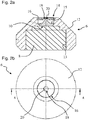
- a setting device 2 comprises a support 6, a field concentration element 10 mounted in the support 6, and a field generator 8.
- the generator the magnet can also be mounted in the support 6.
- the magnet can also be mounted outside the support 6 depending on the geometry of the support, as long as the function of the magnet is filled, to know that it is configured to apply a magnetic field of a desired intensity to the field concentration element 10.
- the support 6 may comprise a body 12 with a cavity 13 in which the field generator 8 may be housed or inserted or only a portion of a field generator, and a housing 15 configured for the assembly and positioning of the field concentration element in the support.
- the support 6 may further comprise an end wall 14 for closing an opening giving access to the housing 15, the end wall 14 comprising a support portion 16 and a tip 18 having a working surface 20.
- the housing 15 for assembling the field concentration element 10 can be accessible from the side of the cavity 13, the end wall 14 in this case being able to be integrally formed with the body 12.
- the working surface 20 may be directly applied and secured to an axial end surface 28 of the field concentrating element 10.
- the housing 15 comprises cylindrical walls and the end wall 14 is substantially in the form of a circular disk with a hole in the center for fixing the end piece 18.
- the material of the working surface 20 is selected from materials having good mechanical properties, and especially having a high hardness as well as good tribological properties. Examples of materials meeting these criteria include corundum, diamond and other precious crystalline stones and some ceramic materials. Natural gemstones can be used to form the tip, or alternatively, apply a synthetic layer by known deposition techniques such as plasma or CVD (chemical vapor deposition).
- the magnet 8 can be made in the form of a permanent magnet, or an electromagnetic magnet.
- the induction coils may be arranged outside the cavity 13 formed in the body 12, the magnetic field being formed by an insert made of a magnetic material, namely a material having a high maximum magnetic permeability, equal to or greater than 100, which is housed in the cavity 13 and abuts or in proximity to an axial base surface 26 of a base portion 22 of the field concentration element.
- the setting device 2 may comprise an electric field generator, for example an electric capacitor, in place and in place of the magnet, in order to apply an electric field, the element of concentration. field 10 for concentrating the electric field.
- the setting device can be used for the measurement or control of non-magnetic organs, or having a low magnetic permeability.
- the setting device may comprise a magnetic field generator and an electric field generator for optionally applying, or simultaneously, an electric field and a magnetic field for centering the device to be measured or control, regulate.
- the meter may include an electrical circuit with a control system to turn off or turn on the magnetic or electrical field and to control the field strength as a function of time.
- the setting device 2 comprises a field concentration element 10 comprising a base portion 22 and a flow concentration portion 24.
- the base portion 22 comprises an axial base surface 26 having a mean width or diameter D2 at its periphery 30b.
- the flux concentration portion 24 has an axial end surface 28 with a diameter D1 smaller than the diameter D2.
- the base portion 22 is connected to the flux concentration portion by a curved surface 33.
- the curved surface 33 has a continuous shape, i.e. without discontinuity and in a form. In particular, this curved surface may follow a substantially toroidal shape with a constant or variable radius of curvature R.
- the profile of the curved surface 33 has an elliptical or parabolic shape, the curvature portion having a large radius being disposed on the side of the flow concentration portion 24.
- the axial height H defining the distance between the axial end surface 28 and the base portion 22 is preferably greater than the radius of curvature R.
- the curved surface joining the flow concentration portion 24 can be connected to this portion of tangential way.
- the flux concentration portion 24 includes a cylindrical section and the axial end surface 28 may have a planar or substantially planar surface orthogonal to the axis A of the setting device.
- the base portion 22 may have an axial thickness for attachment of the field concentrating member in a holder 6.
- the base portion 22 may have different shapes configured for attachment of the setting device in the holder.
- the figure 3a illustrates a field concentrating element with a base portion comprising a flange 34 and a reduced section 36 forming a step sitting in a complementary housing shape as illustrated in FIG. figure 2a .
- the flange 34 may be provided with a polarizing portion, for example a plate 38, to fix the orientation of the field concentration element 10 in the body 12.
- the latter feature may be useful in variants where the element field concentration is placed in the housing 15 and could rotate in the absence of a polarization element due to a rotating magnetic force due to the rotation of the member to be measured or control 3.
- the curved shape 33 and the cylindrical extension of the flux concentration part makes it possible to optimize the concentration of flux, in particular of a magnetic flux, but also the concentration of an electric field in an optimal manner while avoiding a local saturation of the high point.
- the toric or essentially toric shape makes it possible to concentrate the flow in a very small diameter D1 at the end of the field concentration element 10 with field lines in the portion approaching and leaving the end surface.
- axial 28 aligned with the axial direction A for applying to the body to be measured or control 3 a magnetic or electrical field of high intensity concentrated around the axis A and directed in the direction of the axis.
- the diameter D1 of the axial end surface is between 0.15 and 0.6 millimeters
- the diameter or the width D2 of the base portion 22 is between 2 and 3 millimeters
- the radius R is between 1.5 and 3 millimeters, for example at 2 millimeters
- the height H between the axial end surface and the base is between 1 and 2 millimeters, for example between 1 and 1.5 millimeters.
- the measuring instrument 1 can be integrated in an optical control or measuring device, for example comprising an optical camera, in a spectrum of electromagnetic waves visible or not visible to the human eye, for example in a ray machine X or infrared.
- the measuring instrument 1 can also be integrated in a machine with other means for detecting solid forms, for example using ultrasound.
- the measuring apparatus according to the invention advantageously makes it possible to provide a field of view for the member to be measured or controlled free of obstacles.
- AFK502 mild steel can be used for the magnetic field concentration element and rare earth magnets having a saturation field greater than 1 Tesla for the magnetic field generator.
- the flow concentration portion may be according to a magnetically inhomogeneous embodiment and have a higher permeability near its axis of revolution.
Landscapes
- Physics & Mathematics (AREA)
- General Physics & Mathematics (AREA)
- Investigating Or Analyzing Materials By The Use Of Magnetic Means (AREA)
- Length Measuring Devices With Unspecified Measuring Means (AREA)
- Investigating Or Analysing Materials By Optical Means (AREA)
Description
La présente invention concerne un dispositif de posage pour la mesure ou le contrôle de composants de faible taille, notamment pour le centrage d'un composant mobile rotatif ou pivotant. Un domaine d'application particulier de l'invention concerne la mesure ou le contrôle de composants de mécanismes horlogers.The present invention relates to a setting device for measuring or controlling small components, in particular for centering a rotating or rotating mobile component. A particular field of application of the invention relates to measuring or controlling components of watch mechanisms.
La mesure des axes et mobiles horlogers doit être effectuée en positionnant les échantillons, sans induire d'incertitude de mesure. Conventionnellement, plusieurs technologies de mesure sont utilisées pour contrôler toutes les géométries des composants mobiles, ces opérations de contrôle demandant des ressources conséquentes en personnel qualifié et en matériel.The measurement of the axes and watchmakers must be carried out by positioning the samples, without inducing measurement uncertainty. Conventionally, several measurement technologies are used to control all the geometries of mobile components, these control operations requiring substantial resources of qualified personnel and equipment.
Des méthodes de contrôle par vision permettraient une mesure de plusieurs géométries à contrôler, mais la difficulté de ces méthodes est d'assurer que le maintien en position des pièces ne masque pas les surfaces à contrôler. Par ailleurs, pour le posage des pièces horlogères tournantes, il faut assurer que l'axe de rotation soit maintenu continûment en équilibre, sans vibration notable, pendant le test de rotation de la pièce.Vision control methods would allow a measurement of several geometries to be controlled, but the difficulty of these methods is to ensure that the holding in position of the parts does not mask the surfaces to be controlled. Moreover, for the setting of the rotating watch parts, it must be ensured that the axis of rotation is kept continuously in equilibrium, without any noticeable vibration, during the test of rotation of the part.
Les techniques de mesure conventionnelles utilisées à ce jour ne permettent pas de mesurer des défauts d'inclinaisons des mobiles avec une précision inférieure à 100 microns, sur la distance radiale entre les deux extrémités de l'axe du mobile.Conventional measurement techniques used to date do not measure mobile inclination defects with an accuracy less than 100 microns, the radial distance between the two ends of the axis of the mobile.
On connait également du document
Le document
Le document
Un objet de l'invention est de fournir un dispositif de posage pour le contrôle ou la mesure de composants de faible taille, à l'échelle millimétrique ou moins, qui soit précis, fiable, et économique à mettre en oeuvre.An object of the invention is to provide a setting device for the control or the measurement of small components, at the scale millimeter or less, which is accurate, reliable, and economical to implement.
Un objet particulier de l'invention est de fournir un dispositif de posage pour le contrôle ou la mesure par un appareil permettant de visionner des composants de faible taille, qui soit précis, fiable, et économique à mettre en oeuvre.A particular object of the invention is to provide a setting device for the control or measurement by an apparatus for viewing components of small size, which is accurate, reliable, and economical to implement.
Un objet particulier de l'invention est de fournir un dispositif de posage pour le contrôle ou la mesure par un appareil permettant de visionner des composants de mécanismes horlogers, qui soit précis, fiable, et économique à mettre en oeuvre.A particular object of the invention is to provide a setting device for the control or measurement by an apparatus for viewing components of watch mechanisms, which is accurate, reliable, and economical to implement.
Un objet particulier de l'invention est de fournir un appareil de mesure et de contrôle comprenant un dispositif de posage pour le contrôle ou la mesure par un appareil permettant de visionner des composants de faible taille tels que des composants de mécanismes horlogers, qui soit précis, fiable, et économique à mettre en oeuvre.A particular object of the invention is to provide a measuring and control device comprising a setting device for the control or measurement by an apparatus for viewing small components such as components of watch mechanisms, which is accurate reliable and economical to implement.
Il est avantageux de fournir un dispositif de posage intégrant un palier axial à très faible usure pour un organe rotatif.It is advantageous to provide a setting device incorporating an axial bearing with very low wear for a rotary member.
Il est avantageux de fournir un dispositif de posage intégrant un palier axial ayant un rendement élevé.It is advantageous to provide a setting device incorporating an axial bearing having a high efficiency.
Il est avantageux de fournir un dispositif de posage compact et robuste.It is advantageous to provide a compact and robust laying device.
Il est avantageux de fournir un dispositif de posage permettant d'assurer la mise en place rapide d'une pièce à mesurer ou à contrôler par un opérateur non qualifié.It is advantageous to provide a setting device for ensuring the rapid implementation of a workpiece to be measured or controlled by an unqualified operator.
Il est avantageux de fournir un dispositif de posage permettant de maintenir en position stable des pièces tournantes durant la mesure.It is advantageous to provide a setting device for maintaining rotating parts during the measurement in a stable position.
Il est avantageux de fournir un dispositif de posage permettant d'assurer l'orientation de l'axe de rotation des pièces de révolution durant le contrôle des cotes en statique et en dynamique.It is advantageous to provide a setting device for ensuring the orientation of the axis of rotation of the parts of revolution during the control of dimensions in static and dynamic.
Il est avantageux de fournir un appareil de mesure permettant d'accepter des formes de pièces variées, telles que axes longs, courts, étagés, avec roue et pignon, et d'autres composants de mécanismes horlogers.It is advantageous to provide a measuring apparatus for accepting varied part shapes, such as long, short, stepped, wheel and pinion axes, and other components of watch mechanisms.
Des objets de l'invention sont réalisés par un dispositif de posage selon la revendication 1. Les revendications dépendantes décrivent des aspects avantageux de l'invention.Objects of the invention are realized by a setting device according to claim 1. The dependent claims describe advantageous aspects of the invention.
Dans la présente on décrit un dispositif de posage comprenant un support comprenant un corps, une surface de travail disposée sur une face du support, un élément de concentration de champ monté dans un logement du support, et un générateur de champ magnétique et/ou électrique selon la variante. L'élément de concentration de champ comprend une partie de base et une partie de concentration de champ disposées à proximité de la surface de travail, la partie de base comprenant une surface de base axiale ayant une largeur moyenne ou diamètre D2 à sa périphérie plus grand qu'un diamètre D1 de la partie de concentration de flux au niveau d'une surface d'extrémité axiale. La partie de base est reliée à la partie de concentration de flux par une surface courbe.In the present there is described a setting device comprising a support comprising a body, a working surface disposed on one side of the support, a field concentration element mounted in a housing of the support, and a magnetic and / or electric field generator. according to the variant. The field concentration element comprises a base portion and a field concentration portion disposed proximate the work surface, the base portion including an axial base surface having an average width or diameter D2 at its larger periphery. a diameter D1 of the flux concentration part at an axial end surface. The base portion is connected to the flux concentration portion by a curved surface.
La surface courbe de l'élément de concentration a de préférence une forme continue. Dans une variante, la surface courbe suit une forme torique avec un rayon de courbure constant. Dans une autre variante avantageuse, la surface courbe suit une forme torique avec un rayon de courbure variable, la partie de courbure ayant un grand rayon disposé du côté de la partie de concentration de flux. La surface courbe peut avantageusement rejoindre la partie de concentration de flux de manière tangentielle. La partie de concentration de flux peut avantageusement comprendre une section cylindrique et une surface d'extrémité axiale plane ou essentiellement plane orthogonale à l'axe du dispositif de posage.The curved surface of the concentrating element preferably has a continuous shape. In a variant, the curved surface follows a toric shape with a constant radius of curvature. In another advantageous embodiment, the curved surface follows a toric shape with a variable radius of curvature, the curvature portion having a large radius disposed on the side of the flux concentration portion. The curved surface may advantageously join the flow concentration part tangentially. The flow concentration portion may advantageously comprise a section cylindrical and an axial end surface or substantially flat orthogonal to the axis of the setting device.
Dans une forme d'exécution particulière, le diamètre de la surface d'extrémité axiale de l'élément de concentration est compris entre 0,15 et 0,6 millimètres, le diamètre ou la largeur de la partie de base est compris entre 2 et 3 millimètres, et le rayon de la surface courbe est compris entre 1,5 et 4 millimètres.In a particular embodiment, the diameter of the axial end surface of the concentration element is between 0.15 and 0.6 millimeters, the diameter or the width of the base portion is between 2 and 3 millimeters, and the radius of the curved surface is between 1.5 and 4 millimeters.
Dans une forme d'exécution particulière, le matériau de l'élément de concentration de champ est en un acier magnétiquement doux, caractérisé par une perméabilité magnétique maximale µR égale ou supérieure à 100 et un champ coercitif Hc égal ou inférieur à 5 kA/m.In a particular embodiment, the material of the field concentration element is made of a magnetically soft steel, characterized by a maximum magnetic permeability μ R equal to or greater than 100 and a coercive field Hc equal to or less than 5 kA / m.
Dans une forme d'exécution particulière, le matériau de l'élément de concentration de champ est un diélectrique dont la rigidité diélectrique est égale ou supérieure à 10 kV/mm.In a particular embodiment, the material of the field concentration element is a dielectric whose dielectric strength is equal to or greater than 10 kV / mm.
Dans une forme d'exécution particulière, le générateur de champ est un aimant permanent en terres rares ayant un champ de saturation supérieur à 1 Tesla.In a particular embodiment, the field generator is a rare earth permanent magnet having a saturation field greater than 1 Tesla.
Dans une forme d'exécution, le générateur de champ peut comprendre un condensateur électrique.In one embodiment, the field generator may include an electrical capacitor.
Le générateur de champ peut être monté dans une cavité formée dans le corps du support, le générateur de champ venant en butée ou à proximité d'une surface de base axiale d'une partie de l'élément de concentration de champ.The field generator may be mounted in a cavity formed in the body of the support, the field generator abutting or near an axial base surface of a portion of the field concentrating element.
Le matériau de la surface de travail peut avantageusement être choisi parmi des matériaux ayant une grande dureté et de bonnes propriétés tribologiques, comprenant des corindons, le diamant ou d'autres pierres précieuses, et des matières céramiques.The material of the work surface may advantageously be selected from materials having a high hardness and good tribological properties, including corundum, diamond or other precious stones, and ceramic materials.
La surface de travail peut faire partie d'un embout assemblé sur une paroi d'extrémité fermant le logement. Le logement peut comprendre des parois cylindriques et la paroi d'extrémité est sous forme essentiellement d'un disque circulaire avec un orifice au centre pour la fixation de l'embout.The work surface may be part of an end piece assembled on an end wall closing the housing. Housing may include cylindrical walls and the end wall is substantially in the form of a circular disk with a hole in the center for fixing the tip.
Des objets de l'invention sont atteints par un instrument de mesure ou de contrôle de pièces de petite taille selon la revendication 16. On décrit ici un instrument de mesure ou de contrôle comprenant un bâti supportant un premier dispositif de posage et un deuxième dispositif complémentaire de posage, le premier dispositif de posage comprenant un support comprenant un corps, une surface de travail disposée sur une face du support, un élément de concentration de champ monté dans un logement du support, et un générateur de champ magnétique et/ou électrique selon la variante. L'élément de concentration de champ comprend une partie de base et une partie de concentration de champ disposées à proximité de la surface de travail, la partie de base comprenant une surface de base axiale ayant une largeur moyenne ou un diamètre à sa périphérie plus grand qu'un diamètre de la partie de concentration de flux au niveau d'une surface d'extrémité axiale, les deux dispositifs de posage étant alignés sur un même axe A, les dispositifs de posage étant orientés l'un par rapport à l'autre de manière opposée et configurés pour recevoir un organe à mesurer ou à contrôler entre les dispositif de passages.Objects of the invention are achieved by a measuring or control instrument of small parts according to
Le bâti peut avantageusement comprendre un dispositif à glissière permettant de varier la distance entre les deux dispositifs de posage afin de pouvoir mesurer ou contrôler des organes de longueurs différentes.The frame may advantageously comprise a slide device allowing the distance between the two setting devices to be varied in order to be able to measure or control members of different lengths.
Dans une forme d'exécution avantageuse, l'instrument est configuré pour qu'une première extrémité d'un organe à contrôler soit en appui contre un premier des dispositifs de posage, l'autre extrémité étant séparée par un petit espace du dispositif complémentaire de posage. Cette configuration est obtenue en ayant une force d'attraction magnétique et/ou électrique appliquée par le premier dispositif de posage plus grande que par le dispositif complémentaire de posage.In an advantageous embodiment, the instrument is configured so that a first end of a member to be tested bears against a first of the setting devices, the other end being separated by a small space of the complementary device of WCS. This configuration is obtained by having a magnetic and / or electrical attraction force applied by the first laying device greater than by the complementary setting device.
Le dispositif de posage de l'instrument peut avantageusement comprendre l'une ou plusieurs caractéristiques du dispositif décrit précédemment.The instrument setting device may advantageously comprise one or more characteristics of the device described above.
Des buts de l'invention sont aussi atteints par un appareil de mesure ou de contrôle optique comprenant une caméra optique et intégrant l'instrument de mesure ou de contrôle.Objects of the invention are also achieved by an optical measuring or control apparatus comprising an optical camera and incorporating the measuring or control instrument.
D'autres buts et aspects avantageux de l'invention apparaitront à la lecture des revendications, ainsi que de la description détaillée de formes d'exécution ci-après, et des dessins annexés, dans lesquels :
- La
figure 1 est une vue d'un instrument de mesure selon une forme d'exécution de l'invention ; - Les
figures 2a et 2b sont des vues en coupe et de face d'un dispositif de posage selon une forme d'exécution de l'invention ; - La
figure 3a est une vue en perspective d'un élément de concentration de champ d'un dispositif de posage selon une forme d'exécution de l'invention ; - La
figure 3b est une vue de côté d'une variante d'un élément de concentration de champ d'un dispositif de posage selon une forme d'exécution de l'invention ; - Les
figures 4a, 4b sont des photographies prises par une caméra optique d'un appareil de mesure ou de contrôle selon une forme d'exécution de l'invention, un organe à contrôler étant en cours d'inspection, lafigure 4a montrant l'organe entier et lafigure 4b une vue détaillé d'une extrémité de l'organe.
- The
figure 1 is a view of a measuring instrument according to one embodiment of the invention; - The
Figures 2a and 2b are sectional and front views of a setting device according to one embodiment of the invention; - The
figure 3a is a perspective view of a field concentration element of a setting device according to one embodiment of the invention; - The
figure 3b is a side view of a variant of a field concentration element of a setting device according to one embodiment of the invention; - The
Figures 4a, 4b are photographs taken by an optical camera of a measuring or control apparatus according to one embodiment of the invention, a control member being inspected, thefigure 4a showing the entire organ and thefigure 4b a detailed view of one end of the organ.
Faisant référence aux figures, un instrument de mesure 1 selon une forme d'exécution de l'invention comprend un bâti 9 supportant un dispositif de posage 2 et un dispositif complémentaire de posage 4, les deux dispositifs de posage étant alignés sur un même axe A, les dispositifs de posage étant orientés l'un par rapport à l'autre de manière opposée et configurés pour recevoir un organe à mesurer ou à contrôler 3 entre les dispositifs. Le bâti 9 peut comprendre un dispositif à glissière ou d'autres éléments amovibles permettant de varier la distance entre les deux dispositifs de posage 2, 4 afin de pouvoir mesurer ou contrôler des organes de longueurs différentes.Referring to the figures, a measuring instrument 1 according to one embodiment of the invention comprises a
Le dispositif de posage est configuré pour concentrer et diriger un champ magnétique, ou dans une variante un champ électrique, ou encore dans une variante une combinaison d'un champ électrique et d'un champ magnétique, afin de centrer un organe à contrôler ou à mesurer 3 en appliquant, selon la variante, une force magnétostatique et/ou électrostatique sur l'organe.The setting device is configured to focus and direct a magnetic field, or alternatively an electric field, or alternatively a combination of an electric field and a magnetic field, in order to center an organ to be controlled or measure 3 by applying, depending on the variant, a magnetostatic and / or electrostatic force on the member.
Comme illustré à la
Dans une forme d'exécution avantageuse, le dispositif de posage est configuré pour concentrer et diriger un champ magnétique. L'utilisation de composants magnétiques dans des instruments de mesure ou de contrôle pour la mesure ou le contrôle des organes rotatifs de mouvements ou mécanismes horlogers ou d'autres mécanismes micromécaniques, est avantageuse parce qu'elle permet de créer des forces importantes et localisées accompagnées de frottements faibles. Cela permet le maintien en équilibre continu, des mobiles de révolutions horlogers, ayant au moins un arbre ferromagnétique ou très perméable magnétiquement, par un champ magnétique créé par 2 bi-pôles magnétiques parallèles et orientés de sorte qu'ils s'attirent.In an advantageous embodiment, the setting device is configured to focus and direct a magnetic field. The use of magnetic components in measuring or control instruments for the measurement or control of rotating members of movements or clock mechanisms or other micromechanical mechanisms, is advantageous because it allows to create large localized forces accompanied by weak friction. This allows the maintenance in continuous equilibrium, watch revolutions motives, having at least one ferromagnetic shaft or very magnetically permeable, by a magnetic field created by 2 parallel magnetic poles and oriented so that they attract.
Le dispositif complémentaire de posage 4 peut avoir une construction suivant les mêmes principes que le dispositif de posage 2, mais ayant une intensité de champ légèrement différente pour les raisons mentionnées ci-dessus. Dans des situations où l'organe à contrôler 3, du fait de sa construction comprend une extrémité qui est attirée plus fortement que l'autre, les deux dispositifs de surface peuvent également être identiques.The
Faisant maintenant référence aux
Le support 6 peut comprendre un corps 12 avec une cavité 13 dans laquelle le générateur de champ 8 peut être logé ou inséré ou seulement une partie d'un générateur de champ, et un logement 15 configuré pour l'assemblage et le positionnement de l'élément de concentration de champ dans le support. Le support 6 peut comprendre en outre une paroi d'extrémité 14 pour fermer une ouverture donnant accès au logement 15, la paroi d'extrémité 14 comprenant une partie support 16 et un embout 18 présentant une surface de travail 20.The
Dans une variante, le logement 15 pour l'assemblage de l'élément de concentration de champ 10 peut être accessible par le côté de la cavité 13, la paroi d'extrémité 14 dans ce cas pouvant être formée solidairement avec le corps 12. La surface de travail 20, dans une variante, peut être directement appliquée et solidaire d'une surface d'extrémité axiale 28 de l'élément de concentration de champ 10.In a variant, the
Dans une forme d'exécution préférentielle, le logement 15 comprend des parois cylindriques et la paroi d'extrémité 14 est réalisée sous forme essentiellement d'un disque circulaire avec un orifice au centre pour la fixation de l'embout 18.In a preferred embodiment, the
Le matériau de la surface de travail 20 est choisi parmi des matériaux ayant de bonnes propriétés mécaniques, et notamment ayant une dureté élevée ainsi que de bonnes propriétés tribologiques. Des exemples de matériaux répondant à ces critères comprennent des corindons, le diamant et d'autres pierres cristallines précieuses et certaines matières céramiques. On peut utiliser des pierres précieuses naturelles pour former l'embout, ou, dans des variantes, appliquer une couche synthétique par des techniques de déposition connues telles que par plasma ou CVD (chemical vapor déposition).The material of the working
L'aimant 8 peut être réalisé sous la forme d'un aimant permanent, ou d'un aimant électromagnétique. Dans cette deuxième variante, les bobines d'induction peuvent être disposées en dehors de la cavité 13 formée dans le corps 12, le champ magnétique étant formé par un insert en un matériau magnétique, à savoir un matériau ayant une haute perméabilité magnétique maximale, égale ou supérieure à 100, qui est logée dans la cavité 13 et vient en butée ou en proximité d'une surface de base axiale 26 d'une partie de base 22 de l'élément de concentration de champ.The
Dans une autre forme d'exécution, le dispositif de posage 2 peut comprendre un générateur de champ électrique, par exemple un condensateur électrique, en lieu et en place de l'aimant, afin d'appliquer un champ électrique, l'élément de concentration de champ 10 servant à concentrer le champ électrique. Dans cette forme d'exécution, le dispositif de posage peut être utilisé pour la mesure ou le contrôle d'organes amagnétiques, ou ayant une faible perméabilité magnétique. Dans une autre forme d'exécution, le dispositif de posage peut comprendre un générateur de champ magnétique et un générateur de champ électrique pour appliquer à choix, ou simultanément, un champ électrique et un champ magnétique pour le centrage de l'organe à mesurer ou contrôler.In another embodiment, the
L'appareil de mesure peut comprendre un circuit électrique avec un système de contrôle permettant d'éteindre ou d'allumer le champ magnétique ou électrique ainsi que de contrôler l'intensité du champ en fonction du temps.The meter may include an electrical circuit with a control system to turn off or turn on the magnetic or electrical field and to control the field strength as a function of time.
Faisant référence aux
La partie de base 22 peut avoir une épaisseur axiale permettant la fixation de l'élément de concentration de champ dans un support 6. La partie de base 22 peut avoir différentes formes configurées pour la fixation du dispositif de posage dans le support. La
Dans une forme d'exécution avantageuse, notamment pour un appareil de mesure ou de contrôle d'axes mobiles de mouvements de pièces horlogères, le diamètre D1 de la surface d'extrémité axiale est compris entre 0,15 et 0,6 millimètres, le diamètre ou la largeur D2 de la partie de base 22 est compris entre 2 et 3 millimètres, le rayon R est compris entre 1,5 et 3 millimètres, par exemple à 2 millimètres, et la hauteur H entre la surface d'extrémité axiale et la base est comprise entre 1 et 2 millimètres par exemple entre 1 et 1,5 millimètres.In an advantageous embodiment, particularly for a device for measuring or controlling moving axes of movements of watch parts, the diameter D1 of the axial end surface is between 0.15 and 0.6 millimeters, the diameter or the width D2 of the
L'instrument de mesure 1 peut être intégré dans un appareil de contrôle ou de mesure optique, par exemple comprenant une caméra optique, dans un spectre d'ondes électromagnétiques visibles ou non visibles à l'oeil humain, par exemple dans un appareil à rayons X ou à infrarouge. L'instrument de mesure 1 peut également être intégré dans une machine avec d'autres moyens de détection de formes solides par exemple en utilisant des ultrasons. L'appareil de mesure selon l'invention permet avantageusement de fournir un champ de vision à l'organe à mesurer ou à contrôler libre d'obstacles.The measuring instrument 1 can be integrated in an optical control or measuring device, for example comprising an optical camera, in a spectrum of electromagnetic waves visible or not visible to the human eye, for example in a ray machine X or infrared. The measuring instrument 1 can also be integrated in a machine with other means for detecting solid forms, for example using ultrasound. The measuring apparatus according to the invention advantageously makes it possible to provide a field of view for the member to be measured or controlled free of obstacles.
Dans une réalisation particulière utilisant un champ magnétique, on peut utiliser de l'acier doux AFK502 pour le l'élément de concentration de champ magnétique et des aimants en terres rares ayant un champ de saturation supérieur à 1 Tesla pour le générateur de champ magnétique.In a particular embodiment using a magnetic field, AFK502 mild steel can be used for the magnetic field concentration element and rare earth magnets having a saturation field greater than 1 Tesla for the magnetic field generator.
Dans une réalisation particulière utilisant un champ électrique, on peut utiliser utilisant des condensateurs électriques à la place des aimants et un matériau conducteur d'électricité formant l'élément de concentration de champ ou recouvrant l'élément de concentration de champ, par exemple plaqué en or.In a particular embodiment using an electric field, it is possible to use using electric capacitors instead of magnets and an electrically conductive material forming the field concentration element or covering the field concentration element, for example plated in gold.
On notera enfin que la partie de concentration du flux peut être selon une variante de réalisation magnétiquement inhomogène et présenter une perméabilité supérieur près de son axe de révolution.Finally, it should be noted that the flow concentration portion may be according to a magnetically inhomogeneous embodiment and have a higher permeability near its axis of revolution.
Les avantages de cette invention, comprennent les caractéristiques suivantes :
- Grande productivité de mesure
- Répétabilité des conditions de mesure
- Mesure dynamique précise à ± 0.15° du défaut d'inclinaison des mobile tournants horlogers (planches, arbres, spiraux, etc...)
- Mesure dynamique précise à ± 0.005 mm du défaut de centrage et du mal rond des mobiles tournants horlogers (planches, arbres, spiraux, etc...)
- Simple étalonnage et vérification de l'appareil par imagerie magnétique
- Dimensions contenues
- Déplacement facile
- Mise en oeuvre très facile pour chaque pièce
- Possibilité d'activer la rotation par air pulsé
- Aucune géométrie de la pièce n'est cachée par le posage
- Possibilité de mesurer les défauts d'inclinaison, de centrage et du mal rond des pièces horlogères lourdes
- Possibilité de mesurer les défauts d'inclinaison, de centrage, et mal rond des pièces horlogères déséquilibrées
- Interchangeabilité des embouts pour adapter le posage aux différentes configurations des pièces.
- High measurement productivity
- Repeatability of measurement conditions
- Precise dynamic measurement within ± 0.15 ° of the tilt defect of rotating watchmakers (boards, shafts, spirals, etc ...)
- Accurate dynamic measurement within ± 0.005 mm of centering defect and round trouble of rotating watchmakers (boards, trees, spirals, etc ...)
- Simple calibration and verification of the device by magnetic imaging
- Dimensions contained
- Easy move
- Very easy implementation for every room
- Possibility to activate the rotation by forced air
- No geometry of the piece is hidden by the pose
- Ability to measure inclination, centering and roundness defects in heavy watch parts
- Ability to measure tilt, centering, and poorly rounded unbalanced watch parts
- Interchangeability of the end caps to adapt the installation to the different configurations of the parts.
- appareil de mesure 1measuring device 1
-
dispositif de posage 2laying
device 2 -
élément de concentration de champ 10
field concentration element 10 -
partie de base 22
basic portion 22 -
surface de base axiale 26
axial base area 26 -
périphérie 30a, 30b
periphery -
portion polarisant 38polarizing
portion 38 -
partie de concentration de flux 24
flow concentration part 24 -
surface d'extrémité axiale 28
axial end surface 28 -
périphérie 32
periphery 32 -
surface courbe 33
curved surface 33 -
flasque 34
flask 34 -
section réduite 36
reduced section 36 -
support 6
support 6 -
corps 12
body 12 -
cavité 13
cavity 13 -
logement 15
accommodation 15 -
paroi d'extrémité 14
end wall 14 -
partie support 16
support part 16 -
embout 18
mouthpiece 18 -
surface de travail 20
work surface 20 -
générateur de champ 8
field generator 8 - aimant /condensateur électriquemagnet / electrical capacitor
-
dispositif complémentaire de posage 4
complementary posage device 4 -
organe à mesurer / contrôler 3organ to measure /
control 3 -
axe pivotant 5pivoting
axis 5 -
première extrémité 7a
first end 7a -
deuxième extrémité 7b
second end 7b
Claims (19)
- Support device (2) including a support (6) having a body (12), a work surface (20) arranged on a surface of the support, a field concentration element (10) mounted inside a housing (15) of the support, and a field generator (8), the field concentration element including a base portion (22) and a flux concentration portion (24) arranged in proximity to the work surface, the base portion including an axial base surface (26) having a mean width or diameter D2 at the periphery thereof which is greater than a diameter D1 of the flux concentration portion on an axial end surface (28), the base portion being connected to the flux concentration portion by a curved surface (33).
- Device according to the preceding claim, characterized in that the curved surface has a continuous shape.
- Device according to the preceding claim, characterized in that the curved surface has a toroidal shape with a constant radius of curvature R.
- Device according to claim 2, characterized in that the curved surface has a toroidal shape with a variable radius of curvature R, the curved portion having a large radius arranged on the side of the flux concentration portion.
- Device according to any of the preceding three claims, characterized in that the curved surface joins the flux concentration portion tangentially.
- Device according to any of the preceding claims, characterized in that the flux concentration portion includes a cylindrical section and a plane or essentially plane axial end surface (28) orthogonal to the axis A of the support device.
- Device according to any of the preceding claims, characterized in that the diameter D1 of the axial end surface is comprised between 0.15 and 0.6 millimetres, the diameter or the width D2 of the base portion is comprised between 2 and 3 millimetres, the radius R of the curved surface is comprised between 1.5 and 4 millimetres.
- Support device according to any of the preceding claims, characterized in that the material of the field concentration element is a soft steel, characterized by a coercive field equal to or less than 5 kA/m and by maximum magnetic permeability equal to or greater than 100.
- Support device according to any of the preceding claims, characterized in that the field generator is a rare earth permanent magnet having a saturation field of more than 1 Tesla.
- Support device according to any of the preceding claims, characterized in that the field generator includes an electrical capacitor.
- Support device according to any of the preceding claims, characterized in that the field generator is arranged inside a cavity (13) formed in the body of the support, the field generator abutting or being in proximity to an axial base surface (26) of one portion of the field concentration element.
- Support device according to any of the preceding claims, characterized in that the material of the work surface is selected from among corundums, diamond and ceramic materials.
- Support device according to any of the preceding claims, characterized in that the work surface is on an end piece (18) assembled on an end wall (14) closing the housing (15).
- Support device according to the preceding claim, characterized in that the housing includes cylindrical walls and the end wall is made essentially in the form of a circular disc with a central orifice for attaching the end piece.
- Support device according to any of the preceding claims, characterized in that the flux concentration portion is magnetically inhomogeneous, having high permeability close to the axis of revolution thereof.
- Measuring and checking instrument (1) characterized in that the instrument includes a frame (9) supporting a first support device (2) and a second complementary support device (4), the two support devices being aligned on the same axis A, the support devices being oriented in an opposite manner in relation to each other and configured to receive a member (3) to be measured or checked between the devices, at least one of said first and second support devices being formed by a support device according to any of the preceding claims.
- Instrument according to the preceding claim, characterized in that the frame includes a slide device for varying the distance between the two support devices to enable members of different lengths to be measured or checked.
- Instrument according to any of the preceding two claims, characterized in that the instrument is configured so that a first end (7a) of an arbor (5) of a member (3) to be checked is abutting against a first of the support devices (2), the other end (7b) being separated by a small space from the complementary support device (4), the magnetic and/or electrical force of attraction applied by the first support device being greater than that applied by the complementary support device.
- Optical checking or measuring apparatus including an optical camera and an instrument according to any of the preceding three claims.
Priority Applications (4)
| Application Number | Priority Date | Filing Date | Title |
|---|---|---|---|
| EP13198642.4A EP2887007B1 (en) | 2013-12-19 | 2013-12-19 | Setting device for monitoring components |
| JP2014214192A JP6170482B2 (en) | 2013-12-19 | 2014-10-21 | Support device for inspecting parts |
| CN201410785859.8A CN104729405B (en) | 2013-12-19 | 2014-12-18 | Support device for sample work piece |
| HK15112547.6A HK1211689A1 (en) | 2013-12-19 | 2015-12-21 | Support device for checking components |
Applications Claiming Priority (1)
| Application Number | Priority Date | Filing Date | Title |
|---|---|---|---|
| EP13198642.4A EP2887007B1 (en) | 2013-12-19 | 2013-12-19 | Setting device for monitoring components |
Publications (2)
| Publication Number | Publication Date |
|---|---|
| EP2887007A1 EP2887007A1 (en) | 2015-06-24 |
| EP2887007B1 true EP2887007B1 (en) | 2017-08-02 |
Family
ID=49911257
Family Applications (1)
| Application Number | Title | Priority Date | Filing Date |
|---|---|---|---|
| EP13198642.4A Active EP2887007B1 (en) | 2013-12-19 | 2013-12-19 | Setting device for monitoring components |
Country Status (4)
| Country | Link |
|---|---|
| EP (1) | EP2887007B1 (en) |
| JP (1) | JP6170482B2 (en) |
| CN (1) | CN104729405B (en) |
| HK (1) | HK1211689A1 (en) |
Cited By (2)
| Publication number | Priority date | Publication date | Assignee | Title |
|---|---|---|---|---|
| WO2020127046A1 (en) | 2018-12-18 | 2020-06-25 | Eta Sa Manufacture Horlogère Suisse | Geometric control device for timepiece mobiles |
| CH718668A1 (en) * | 2021-05-27 | 2022-11-30 | Atmen Solution Toni Orhanovic | Detachable mounting frame suitable for mounting on a tester for inspection of small parts. |
Families Citing this family (2)
| Publication number | Priority date | Publication date | Assignee | Title |
|---|---|---|---|---|
| EP4016199A1 (en) * | 2020-12-16 | 2022-06-22 | Rolex Sa | Device and method for testing a mechanical property of a timepiece arbour |
| RU2760842C1 (en) * | 2021-02-03 | 2021-11-30 | Общество с ограниченной ответственностью Научно-производственное предприятие "МЕТЧИВ" (ООО НПП "МЕТЧИВ") | Method for radial forging of pipes |
Family Cites Families (6)
| Publication number | Priority date | Publication date | Assignee | Title |
|---|---|---|---|---|
| BE528187A (en) * | 1953-04-22 | 1900-01-01 | ||
| US4340038A (en) * | 1980-12-15 | 1982-07-20 | Pacesetter Systems, Inc. | Magnetic field concentration means and method for an implanted device |
| JPH0374304U (en) * | 1989-11-21 | 1991-07-25 | ||
| EP2450758B1 (en) * | 2010-11-09 | 2017-01-04 | Montres Breguet SA | Magnetic pivot and electrostatic pivot |
| JP2012225816A (en) * | 2011-04-21 | 2012-11-15 | Nsk Ltd | Peripheral surface measuring apparatus of rolling member |
| WO2012160132A1 (en) * | 2011-05-25 | 2012-11-29 | Helmut Fischer GmbH Institut für Elektronik und Messtechnik | Measuring probe for measuring the thickness of thin layers, and method for the production of a sensor element for the measuring probe |
-
2013
- 2013-12-19 EP EP13198642.4A patent/EP2887007B1/en active Active
-
2014
- 2014-10-21 JP JP2014214192A patent/JP6170482B2/en active Active
- 2014-12-18 CN CN201410785859.8A patent/CN104729405B/en active Active
-
2015
- 2015-12-21 HK HK15112547.6A patent/HK1211689A1/en unknown
Non-Patent Citations (1)
| Title |
|---|
| None * |
Cited By (2)
| Publication number | Priority date | Publication date | Assignee | Title |
|---|---|---|---|---|
| WO2020127046A1 (en) | 2018-12-18 | 2020-06-25 | Eta Sa Manufacture Horlogère Suisse | Geometric control device for timepiece mobiles |
| CH718668A1 (en) * | 2021-05-27 | 2022-11-30 | Atmen Solution Toni Orhanovic | Detachable mounting frame suitable for mounting on a tester for inspection of small parts. |
Also Published As
| Publication number | Publication date |
|---|---|
| CN104729405B (en) | 2019-03-15 |
| CN104729405A (en) | 2015-06-24 |
| EP2887007A1 (en) | 2015-06-24 |
| JP6170482B2 (en) | 2017-07-26 |
| HK1211689A1 (en) | 2016-05-27 |
| JP2015118080A (en) | 2015-06-25 |
Similar Documents
| Publication | Publication Date | Title |
|---|---|---|
| EP2887007B1 (en) | Setting device for monitoring components | |
| EP2450758B1 (en) | Magnetic pivot and electrostatic pivot | |
| EP1989505B1 (en) | Position sensor with variable direction of magnetization and method of production | |
| EP1949036B1 (en) | Magnetic angular position sensor for a course up to 360° | |
| EP2470921B1 (en) | Cylindrical permanent magnet device generating a controlled magnetic field at a distance from the surface thereof | |
| FR2985820A1 (en) | VARIABLE FOCAL OBJECTIVE APPARATUS WITH FOCUS ADJUSTMENT AND OPTICAL IMAGING DEVICE THEREFOR | |
| FR2537301A1 (en) | ELECTRO-MECHANICAL CONVERTER WITH SEVERAL DEGREES OF FREEDOM | |
| WO1996008727A1 (en) | Speed and/or position incremental sensor | |
| EP0541653A1 (en) | Permanent magnet for nmr imaging equipment. | |
| EP3790166B1 (en) | Magnetic actuator and mechatronic system | |
| FR3024233A1 (en) | MACHINE ELEMENT AND DEVICE FOR MEASURING FORCE OR MOMENT AND METHOD OF MAKING THE MACHINE ELEMENT | |
| FR2889740A1 (en) | ELECTROMAGNETIC DEBITMETER | |
| FR2748805A1 (en) | CONTACTLESS POSITION SENSOR, HALL EFFECT | |
| CH709006A2 (en) | A tombstone for the control components. | |
| WO2015128592A1 (en) | Magnetic sensor for determining the relative position between a magnetized target and a measurement system | |
| EP3489768B1 (en) | Magnetic device for centring an arbour in a clock movement | |
| CH709005A2 (en) | Magnetic centering. | |
| EP1166295B1 (en) | Method for determining the position of a moveable element in at least one main pole air gap in an electromagnetic actuator | |
| FR2788163A1 (en) | ELECTROMAGNETIC ACTUATOR EQUIPPED WITH MEANS FOR ADJUSTING THE POSITION OF ITS MOBILE POLAR ELEMENT | |
| FR2644930A1 (en) | VARIABLE FOCAL COMPOSITE ELECTROMAGNETIC LENS | |
| CH633888A5 (en) | SUPPORT DEVICE FOR TRANSDUCER. | |
| EP2828610B1 (en) | Device for positioning an object in space | |
| WO2023148563A1 (en) | Magnet assembly for electrodynamic loudspeaker motor, electrodynamic loudspeaker motor comprising same, and associated electrodynamic loudspeaker | |
| EP1135781A1 (en) | Bidirectional actuators | |
| FR2493510A1 (en) | ALIGNMENT DETECTION APPARATUS |
Legal Events
| Date | Code | Title | Description |
|---|---|---|---|
| PUAI | Public reference made under article 153(3) epc to a published international application that has entered the european phase |
Free format text: ORIGINAL CODE: 0009012 |
|
| 17P | Request for examination filed |
Effective date: 20131219 |
|
| AK | Designated contracting states |
Kind code of ref document: A1 Designated state(s): AL AT BE BG CH CY CZ DE DK EE ES FI FR GB GR HR HU IE IS IT LI LT LU LV MC MK MT NL NO PL PT RO RS SE SI SK SM TR |
|
| AX | Request for extension of the european patent |
Extension state: BA ME |
|
| R17P | Request for examination filed (corrected) |
Effective date: 20150728 |
|
| RBV | Designated contracting states (corrected) |
Designated state(s): AL AT BE BG CH CY CZ DE DK EE ES FI FR GB GR HR HU IE IS IT LI LT LU LV MC MK MT NL NO PL PT RO RS SE SI SK SM TR |
|
| GRAP | Despatch of communication of intention to grant a patent |
Free format text: ORIGINAL CODE: EPIDOSNIGR1 |
|
| INTG | Intention to grant announced |
Effective date: 20170508 |
|
| GRAS | Grant fee paid |
Free format text: ORIGINAL CODE: EPIDOSNIGR3 |
|
| GRAA | (expected) grant |
Free format text: ORIGINAL CODE: 0009210 |
|
| AK | Designated contracting states |
Kind code of ref document: B1 Designated state(s): AL AT BE BG CH CY CZ DE DK EE ES FI FR GB GR HR HU IE IS IT LI LT LU LV MC MK MT NL NO PL PT RO RS SE SI SK SM TR |
|
| REG | Reference to a national code |
Ref country code: CH Ref legal event code: EP Ref country code: CH Ref legal event code: NV Representative=s name: ICB INGENIEURS CONSEILS EN BREVETS SA, CH Ref country code: AT Ref legal event code: REF Ref document number: 914953 Country of ref document: AT Kind code of ref document: T Effective date: 20170815 |
|
| REG | Reference to a national code |
Ref country code: IE Ref legal event code: FG4D Free format text: LANGUAGE OF EP DOCUMENT: FRENCH |
|
| REG | Reference to a national code |
Ref country code: DE Ref legal event code: R096 Ref document number: 602013024303 Country of ref document: DE |
|
| REG | Reference to a national code |
Ref country code: FR Ref legal event code: PLFP Year of fee payment: 5 |
|
| REG | Reference to a national code |
Ref country code: NL Ref legal event code: MP Effective date: 20170802 |
|
| REG | Reference to a national code |
Ref country code: AT Ref legal event code: MK05 Ref document number: 914953 Country of ref document: AT Kind code of ref document: T Effective date: 20170802 |
|
| REG | Reference to a national code |
Ref country code: LT Ref legal event code: MG4D |
|
| PG25 | Lapsed in a contracting state [announced via postgrant information from national office to epo] |
Ref country code: NO Free format text: LAPSE BECAUSE OF FAILURE TO SUBMIT A TRANSLATION OF THE DESCRIPTION OR TO PAY THE FEE WITHIN THE PRESCRIBED TIME-LIMIT Effective date: 20171102 Ref country code: LT Free format text: LAPSE BECAUSE OF FAILURE TO SUBMIT A TRANSLATION OF THE DESCRIPTION OR TO PAY THE FEE WITHIN THE PRESCRIBED TIME-LIMIT Effective date: 20170802 Ref country code: HR Free format text: LAPSE BECAUSE OF FAILURE TO SUBMIT A TRANSLATION OF THE DESCRIPTION OR TO PAY THE FEE WITHIN THE PRESCRIBED TIME-LIMIT Effective date: 20170802 Ref country code: SE Free format text: LAPSE BECAUSE OF FAILURE TO SUBMIT A TRANSLATION OF THE DESCRIPTION OR TO PAY THE FEE WITHIN THE PRESCRIBED TIME-LIMIT Effective date: 20170802 Ref country code: NL Free format text: LAPSE BECAUSE OF FAILURE TO SUBMIT A TRANSLATION OF THE DESCRIPTION OR TO PAY THE FEE WITHIN THE PRESCRIBED TIME-LIMIT Effective date: 20170802 Ref country code: FI Free format text: LAPSE BECAUSE OF FAILURE TO SUBMIT A TRANSLATION OF THE DESCRIPTION OR TO PAY THE FEE WITHIN THE PRESCRIBED TIME-LIMIT Effective date: 20170802 Ref country code: AT Free format text: LAPSE BECAUSE OF FAILURE TO SUBMIT A TRANSLATION OF THE DESCRIPTION OR TO PAY THE FEE WITHIN THE PRESCRIBED TIME-LIMIT Effective date: 20170802 |
|
| PG25 | Lapsed in a contracting state [announced via postgrant information from national office to epo] |
Ref country code: ES Free format text: LAPSE BECAUSE OF FAILURE TO SUBMIT A TRANSLATION OF THE DESCRIPTION OR TO PAY THE FEE WITHIN THE PRESCRIBED TIME-LIMIT Effective date: 20170802 Ref country code: BG Free format text: LAPSE BECAUSE OF FAILURE TO SUBMIT A TRANSLATION OF THE DESCRIPTION OR TO PAY THE FEE WITHIN THE PRESCRIBED TIME-LIMIT Effective date: 20171102 Ref country code: GR Free format text: LAPSE BECAUSE OF FAILURE TO SUBMIT A TRANSLATION OF THE DESCRIPTION OR TO PAY THE FEE WITHIN THE PRESCRIBED TIME-LIMIT Effective date: 20171103 Ref country code: PL Free format text: LAPSE BECAUSE OF FAILURE TO SUBMIT A TRANSLATION OF THE DESCRIPTION OR TO PAY THE FEE WITHIN THE PRESCRIBED TIME-LIMIT Effective date: 20170802 Ref country code: LV Free format text: LAPSE BECAUSE OF FAILURE TO SUBMIT A TRANSLATION OF THE DESCRIPTION OR TO PAY THE FEE WITHIN THE PRESCRIBED TIME-LIMIT Effective date: 20170802 Ref country code: RS Free format text: LAPSE BECAUSE OF FAILURE TO SUBMIT A TRANSLATION OF THE DESCRIPTION OR TO PAY THE FEE WITHIN THE PRESCRIBED TIME-LIMIT Effective date: 20170802 Ref country code: IS Free format text: LAPSE BECAUSE OF FAILURE TO SUBMIT A TRANSLATION OF THE DESCRIPTION OR TO PAY THE FEE WITHIN THE PRESCRIBED TIME-LIMIT Effective date: 20171202 |
|
| PG25 | Lapsed in a contracting state [announced via postgrant information from national office to epo] |
Ref country code: DK Free format text: LAPSE BECAUSE OF FAILURE TO SUBMIT A TRANSLATION OF THE DESCRIPTION OR TO PAY THE FEE WITHIN THE PRESCRIBED TIME-LIMIT Effective date: 20170802 Ref country code: RO Free format text: LAPSE BECAUSE OF FAILURE TO SUBMIT A TRANSLATION OF THE DESCRIPTION OR TO PAY THE FEE WITHIN THE PRESCRIBED TIME-LIMIT Effective date: 20170802 Ref country code: CZ Free format text: LAPSE BECAUSE OF FAILURE TO SUBMIT A TRANSLATION OF THE DESCRIPTION OR TO PAY THE FEE WITHIN THE PRESCRIBED TIME-LIMIT Effective date: 20170802 |
|
| REG | Reference to a national code |
Ref country code: DE Ref legal event code: R097 Ref document number: 602013024303 Country of ref document: DE |
|
| PG25 | Lapsed in a contracting state [announced via postgrant information from national office to epo] |
Ref country code: SM Free format text: LAPSE BECAUSE OF FAILURE TO SUBMIT A TRANSLATION OF THE DESCRIPTION OR TO PAY THE FEE WITHIN THE PRESCRIBED TIME-LIMIT Effective date: 20170802 Ref country code: IT Free format text: LAPSE BECAUSE OF FAILURE TO SUBMIT A TRANSLATION OF THE DESCRIPTION OR TO PAY THE FEE WITHIN THE PRESCRIBED TIME-LIMIT Effective date: 20170802 Ref country code: SK Free format text: LAPSE BECAUSE OF FAILURE TO SUBMIT A TRANSLATION OF THE DESCRIPTION OR TO PAY THE FEE WITHIN THE PRESCRIBED TIME-LIMIT Effective date: 20170802 Ref country code: EE Free format text: LAPSE BECAUSE OF FAILURE TO SUBMIT A TRANSLATION OF THE DESCRIPTION OR TO PAY THE FEE WITHIN THE PRESCRIBED TIME-LIMIT Effective date: 20170802 |
|
| PLBE | No opposition filed within time limit |
Free format text: ORIGINAL CODE: 0009261 |
|
| STAA | Information on the status of an ep patent application or granted ep patent |
Free format text: STATUS: NO OPPOSITION FILED WITHIN TIME LIMIT |
|
| 26N | No opposition filed |
Effective date: 20180503 |
|
| PG25 | Lapsed in a contracting state [announced via postgrant information from national office to epo] |
Ref country code: SI Free format text: LAPSE BECAUSE OF FAILURE TO SUBMIT A TRANSLATION OF THE DESCRIPTION OR TO PAY THE FEE WITHIN THE PRESCRIBED TIME-LIMIT Effective date: 20170802 |
|
| REG | Reference to a national code |
Ref country code: IE Ref legal event code: MM4A |
|
| PG25 | Lapsed in a contracting state [announced via postgrant information from national office to epo] |
Ref country code: MT Free format text: LAPSE BECAUSE OF FAILURE TO SUBMIT A TRANSLATION OF THE DESCRIPTION OR TO PAY THE FEE WITHIN THE PRESCRIBED TIME-LIMIT Effective date: 20170802 Ref country code: LU Free format text: LAPSE BECAUSE OF NON-PAYMENT OF DUE FEES Effective date: 20171219 |
|
| REG | Reference to a national code |
Ref country code: BE Ref legal event code: MM Effective date: 20171231 |
|
| PG25 | Lapsed in a contracting state [announced via postgrant information from national office to epo] |
Ref country code: IE Free format text: LAPSE BECAUSE OF NON-PAYMENT OF DUE FEES Effective date: 20171219 |
|
| PG25 | Lapsed in a contracting state [announced via postgrant information from national office to epo] |
Ref country code: BE Free format text: LAPSE BECAUSE OF NON-PAYMENT OF DUE FEES Effective date: 20171231 |
|
| PG25 | Lapsed in a contracting state [announced via postgrant information from national office to epo] |
Ref country code: MC Free format text: LAPSE BECAUSE OF FAILURE TO SUBMIT A TRANSLATION OF THE DESCRIPTION OR TO PAY THE FEE WITHIN THE PRESCRIBED TIME-LIMIT Effective date: 20170802 Ref country code: HU Free format text: LAPSE BECAUSE OF FAILURE TO SUBMIT A TRANSLATION OF THE DESCRIPTION OR TO PAY THE FEE WITHIN THE PRESCRIBED TIME-LIMIT; INVALID AB INITIO Effective date: 20131219 |
|
| PG25 | Lapsed in a contracting state [announced via postgrant information from national office to epo] |
Ref country code: CY Free format text: LAPSE BECAUSE OF FAILURE TO SUBMIT A TRANSLATION OF THE DESCRIPTION OR TO PAY THE FEE WITHIN THE PRESCRIBED TIME-LIMIT Effective date: 20170802 |
|
| PG25 | Lapsed in a contracting state [announced via postgrant information from national office to epo] |
Ref country code: MK Free format text: LAPSE BECAUSE OF FAILURE TO SUBMIT A TRANSLATION OF THE DESCRIPTION OR TO PAY THE FEE WITHIN THE PRESCRIBED TIME-LIMIT Effective date: 20170802 |
|
| PG25 | Lapsed in a contracting state [announced via postgrant information from national office to epo] |
Ref country code: TR Free format text: LAPSE BECAUSE OF FAILURE TO SUBMIT A TRANSLATION OF THE DESCRIPTION OR TO PAY THE FEE WITHIN THE PRESCRIBED TIME-LIMIT Effective date: 20170802 |
|
| PG25 | Lapsed in a contracting state [announced via postgrant information from national office to epo] |
Ref country code: PT Free format text: LAPSE BECAUSE OF FAILURE TO SUBMIT A TRANSLATION OF THE DESCRIPTION OR TO PAY THE FEE WITHIN THE PRESCRIBED TIME-LIMIT Effective date: 20170802 |
|
| PG25 | Lapsed in a contracting state [announced via postgrant information from national office to epo] |
Ref country code: AL Free format text: LAPSE BECAUSE OF FAILURE TO SUBMIT A TRANSLATION OF THE DESCRIPTION OR TO PAY THE FEE WITHIN THE PRESCRIBED TIME-LIMIT Effective date: 20170802 |
|
| P01 | Opt-out of the competence of the unified patent court (upc) registered |
Effective date: 20230611 |
|
| PGFP | Annual fee paid to national office [announced via postgrant information from national office to epo] |
Ref country code: GB Payment date: 20231121 Year of fee payment: 11 |
|
| PGFP | Annual fee paid to national office [announced via postgrant information from national office to epo] |
Ref country code: FR Payment date: 20231122 Year of fee payment: 11 Ref country code: DE Payment date: 20231121 Year of fee payment: 11 |
|
| PGFP | Annual fee paid to national office [announced via postgrant information from national office to epo] |
Ref country code: CH Payment date: 20240102 Year of fee payment: 11 |