EP2886858B2 - Éolienne avec système de pas de pale - Google Patents
Éolienne avec système de pas de pale Download PDFInfo
- Publication number
- EP2886858B2 EP2886858B2 EP14198672.9A EP14198672A EP2886858B2 EP 2886858 B2 EP2886858 B2 EP 2886858B2 EP 14198672 A EP14198672 A EP 14198672A EP 2886858 B2 EP2886858 B2 EP 2886858B2
- Authority
- EP
- European Patent Office
- Prior art keywords
- blade
- bearing
- driving plate
- wind turbine
- moving ring
- Prior art date
- Legal status (The legal status is an assumption and is not a legal conclusion. Google has not performed a legal analysis and makes no representation as to the accuracy of the status listed.)
- Active
Links
- 238000003754 machining Methods 0.000 description 9
- 238000004519 manufacturing process Methods 0.000 description 4
- 238000000034 method Methods 0.000 description 2
- 230000009286 beneficial effect Effects 0.000 description 1
- 238000005266 casting Methods 0.000 description 1
- 230000003247 decreasing effect Effects 0.000 description 1
- 230000005484 gravity Effects 0.000 description 1
- 238000009434 installation Methods 0.000 description 1
- 230000010354 integration Effects 0.000 description 1
- 238000005304 joining Methods 0.000 description 1
- 239000000463 material Substances 0.000 description 1
- 230000013011 mating Effects 0.000 description 1
- 239000002994 raw material Substances 0.000 description 1
- 230000000284 resting effect Effects 0.000 description 1
- 238000000926 separation method Methods 0.000 description 1
- 239000002699 waste material Substances 0.000 description 1
Images
Classifications
-
- F—MECHANICAL ENGINEERING; LIGHTING; HEATING; WEAPONS; BLASTING
- F03—MACHINES OR ENGINES FOR LIQUIDS; WIND, SPRING, OR WEIGHT MOTORS; PRODUCING MECHANICAL POWER OR A REACTIVE PROPULSIVE THRUST, NOT OTHERWISE PROVIDED FOR
- F03D—WIND MOTORS
- F03D7/00—Controlling wind motors
- F03D7/02—Controlling wind motors the wind motors having rotation axis substantially parallel to the air flow entering the rotor
- F03D7/022—Adjusting aerodynamic properties of the blades
- F03D7/0224—Adjusting blade pitch
-
- F—MECHANICAL ENGINEERING; LIGHTING; HEATING; WEAPONS; BLASTING
- F03—MACHINES OR ENGINES FOR LIQUIDS; WIND, SPRING, OR WEIGHT MOTORS; PRODUCING MECHANICAL POWER OR A REACTIVE PROPULSIVE THRUST, NOT OTHERWISE PROVIDED FOR
- F03D—WIND MOTORS
- F03D1/00—Wind motors with rotation axis substantially parallel to the air flow entering the rotor
- F03D1/06—Rotors
- F03D1/065—Rotors characterised by their construction elements
- F03D1/0658—Arrangements for fixing wind-engaging parts to a hub
-
- F—MECHANICAL ENGINEERING; LIGHTING; HEATING; WEAPONS; BLASTING
- F03—MACHINES OR ENGINES FOR LIQUIDS; WIND, SPRING, OR WEIGHT MOTORS; PRODUCING MECHANICAL POWER OR A REACTIVE PROPULSIVE THRUST, NOT OTHERWISE PROVIDED FOR
- F03D—WIND MOTORS
- F03D1/00—Wind motors with rotation axis substantially parallel to the air flow entering the rotor
- F03D1/06—Rotors
- F03D1/065—Rotors characterised by their construction elements
- F03D1/0691—Rotors characterised by their construction elements of the hub
-
- F—MECHANICAL ENGINEERING; LIGHTING; HEATING; WEAPONS; BLASTING
- F03—MACHINES OR ENGINES FOR LIQUIDS; WIND, SPRING, OR WEIGHT MOTORS; PRODUCING MECHANICAL POWER OR A REACTIVE PROPULSIVE THRUST, NOT OTHERWISE PROVIDED FOR
- F03D—WIND MOTORS
- F03D7/00—Controlling wind motors
- F03D7/02—Controlling wind motors the wind motors having rotation axis substantially parallel to the air flow entering the rotor
- F03D7/04—Automatic control; Regulation
-
- F—MECHANICAL ENGINEERING; LIGHTING; HEATING; WEAPONS; BLASTING
- F03—MACHINES OR ENGINES FOR LIQUIDS; WIND, SPRING, OR WEIGHT MOTORS; PRODUCING MECHANICAL POWER OR A REACTIVE PROPULSIVE THRUST, NOT OTHERWISE PROVIDED FOR
- F03D—WIND MOTORS
- F03D80/00—Details, components or accessories not provided for in groups F03D1/00 - F03D17/00
- F03D80/70—Bearing or lubricating arrangements
-
- F—MECHANICAL ENGINEERING; LIGHTING; HEATING; WEAPONS; BLASTING
- F05—INDEXING SCHEMES RELATING TO ENGINES OR PUMPS IN VARIOUS SUBCLASSES OF CLASSES F01-F04
- F05B—INDEXING SCHEME RELATING TO WIND, SPRING, WEIGHT, INERTIA OR LIKE MOTORS, TO MACHINES OR ENGINES FOR LIQUIDS COVERED BY SUBCLASSES F03B, F03D AND F03G
- F05B2250/00—Geometry
- F05B2250/30—Arrangement of components
- F05B2250/31—Arrangement of components according to the direction of their main axis or their axis of rotation
- F05B2250/311—Arrangement of components according to the direction of their main axis or their axis of rotation the axes being in line
-
- F—MECHANICAL ENGINEERING; LIGHTING; HEATING; WEAPONS; BLASTING
- F05—INDEXING SCHEMES RELATING TO ENGINES OR PUMPS IN VARIOUS SUBCLASSES OF CLASSES F01-F04
- F05B—INDEXING SCHEME RELATING TO WIND, SPRING, WEIGHT, INERTIA OR LIKE MOTORS, TO MACHINES OR ENGINES FOR LIQUIDS COVERED BY SUBCLASSES F03B, F03D AND F03G
- F05B2250/00—Geometry
- F05B2250/30—Arrangement of components
- F05B2250/31—Arrangement of components according to the direction of their main axis or their axis of rotation
- F05B2250/314—Arrangement of components according to the direction of their main axis or their axis of rotation the axes being inclined in relation to each other
-
- F—MECHANICAL ENGINEERING; LIGHTING; HEATING; WEAPONS; BLASTING
- F05—INDEXING SCHEMES RELATING TO ENGINES OR PUMPS IN VARIOUS SUBCLASSES OF CLASSES F01-F04
- F05B—INDEXING SCHEME RELATING TO WIND, SPRING, WEIGHT, INERTIA OR LIKE MOTORS, TO MACHINES OR ENGINES FOR LIQUIDS COVERED BY SUBCLASSES F03B, F03D AND F03G
- F05B2260/00—Function
- F05B2260/70—Adjusting of angle of incidence or attack of rotating blades
- F05B2260/79—Bearing, support or actuation arrangements therefor
-
- Y—GENERAL TAGGING OF NEW TECHNOLOGICAL DEVELOPMENTS; GENERAL TAGGING OF CROSS-SECTIONAL TECHNOLOGIES SPANNING OVER SEVERAL SECTIONS OF THE IPC; TECHNICAL SUBJECTS COVERED BY FORMER USPC CROSS-REFERENCE ART COLLECTIONS [XRACs] AND DIGESTS
- Y02—TECHNOLOGIES OR APPLICATIONS FOR MITIGATION OR ADAPTATION AGAINST CLIMATE CHANGE
- Y02E—REDUCTION OF GREENHOUSE GAS [GHG] EMISSIONS, RELATED TO ENERGY GENERATION, TRANSMISSION OR DISTRIBUTION
- Y02E10/00—Energy generation through renewable energy sources
- Y02E10/70—Wind energy
- Y02E10/72—Wind turbines with rotation axis in wind direction
Definitions
- the present invention relates to a wind turbine with blade pitch system with an angle between the longitudinal direction of the blade and the axis of rotation of the bearing of the blade pitch system, thus increasing the separation between the blade and the tower and reducing the loads in the actuator of the blade pitch system.
- the object of the present invention is to provide a wind turbine blade pitch system in which the number of system components is reduced, thus reducing the number of connections between components, leading to a reduction in the number of assembly tasks and pre-stressed connecting bolt operations.
- the blade pitch system in wind turbines consists of a bearing on which the blade is attached.
- This bearing is joined by one part, i.e. the fixed or stationary part, to the hub, whilst the moving part is joined on one side to the blade and on the other side, the part located inside the hub, to a driving plate.
- the said blade in turn, is connected, by means of a hydraulic or electric actuator, to the hub which makes the blade to rotate.
- a hydraulic actuator moves the driving plate through a ball joint system.
- the driving plate has two functions: on the one hand it stiffens the hub, that is, it has a structural function and on the other hand it acts as a link in the blade pitch drivetrain system.
- the bearing has the dimensions of the blade root and is generally a bearing in which the contacting surfaces with the blade and the driving plate are perpendicular to the axis of rotation of the blade pitch bearing so that the longitudinal direction of the blade is coincident with the axis of the bearing, wherein said driving plate in turn has its bearing contact surface perpendicular to the longitudinal direction of the blade.
- This geometric aspect is very important as it permits a lightening of the blade designs and of the other components of the wind turbine.
- To achieve the preconing angle there are two possible alternatives: arranging the surfaces of the moving bearing ring so that they are not parallel to their axis, by means of machining, as disclosed in European patent application EP2336553A1 , or by machining the blade root to the required angle.
- loads may vary from one wind turbine to another depending on the blade used, making it difficult to maintain the same platform.
- One way of resolving this is to customize the preconing angle for each rotor. It is therefore of great interest to employ methods and techniques that allow the distance between the blade and the tower to be easily adapted from one platform to another.
- Wind turbine systems with blade pitch actuation systems known in the prior art comprise a bearing, a driving plate, a shaft or ball joint system and a hydraulic linear actuator, wherein the blade is arranged in contact with a first surface of the moving bearing ring, and the driving plate, also called pitch plate, is placed in contact with a second flank of the moving bearing ring facing the interior of the hub.
- the driving plate is connected to the actuator which is joined to the hub through a ball joint system.
- the fixed bearing ring is attached to the hub of the nacelle.
- the introduction of the ball joint system is necessary because the angle formed between the longitudinal axis of the blade and the rotational axis of the fixed bearing ring makes it necessary for the actuator to manoeuvre, rotating with a conical rather than cylindrical orbit. If the orbit was perfectly cylindrical the said ball joint system would not be necessary.
- the driving plate and the shaft, or ball joint system are manufactured separately and assembled subsequently, generally using bolts to connect them.
- US2013/216394A1 discloses a wind turbine with blade pitch system.
- the present invention relates to a wind turbine with blade pitch system according to claim 1.
- the driving plate has a rear face disposed in contact with the blade and a front face disposed in contact with a rear face of the moving ring of the bearing, where the rear face of the driving plate is perpendicular to the longitudinal direction of the blade and the front face of the driving plate is perpendicular to the bearing axis.
- the faces of the driving plate form an angle other than 0°, preferably an angle greater than 0° and less than or equal to 5°. This angle is the preconing angle, the angle between the axis of rotation of the blade pitch system bearing and the longitudinal direction of the blade.
- the complexity of the blade pitch system is reduced to a single component, the driving plate, which adopts the necessary preconing angle for an adequate design of the wind turbine.
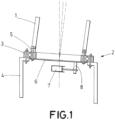
- the wind turbine comprises:
- the actuator (7) is preferably a hydraulic actuator with a fixed housing joined to the hub (4) and a moving piston joined to the shaft (8) or ball joint system.
- the driving plate (6) comprises a rear face (12) disposed in contact with the blade (1) forming an angle with a front face (15) of the driving plate (6) disposed in contact with a rear face (16) of the moving ring (5) of the bearing (2).
- This angle is the preconing angle: the angle between the axis of rotation of the bearing (2) of the blade pitch system and the longitudinal direction of the blade (1).
- This angle can be any angle from 0° to appropriate values for each wind turbine, but an angle of 0° is not claimed.
- the preconing angle will be between 1° and 5°.
- the wind turbine further comprises attachment means (9, 10) that join the blade (1), the driving plate (6) and the moving ring (5) of the bearing (2), wherein said attachment means (9, 10) comprise bolts (9) arranged in holes (14) passing through the moving ring (5) of the bearing (2), the driving plate (6) and the root of the blade (1), bolts (9) which are arranged parallel to the longitudinal direction of the blade (1), optimally dividing load at the root of the blade (1), in the driving plate (6) and the bearing (2).
- the attachment means (9, 10) further comprise nuts (10) that allow the assembly of the blade (1), the driving plate (9) and the moving ring (5) of the bearing (2) through the bolts (9) arranged in the holes (14) passing through the moving ring (5) of the bearing (2), the driving plate (6) and the root of the blade (1).
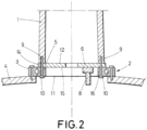
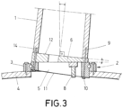
- a front face (11) of the moving ring (5) of the bearing (2) facing the interior of the hub (4) is perpendicular to the longitudinal axis of the blade (1) so that the bolts (9) continue to be parallel to the longitudinal direction of the blade (1) and the fixing nuts (10) rest in the front face (11) of the moving ring (5) of the bearing (2), and where additionally the front face (11) of the moving ring (5) of the bearing (2) is parallel to the rear face (12) of the driving plate (6), as shown in figure 3 .
- the front face (11) of the moving ring (5) of the bearing (2) is not perpendicular to the longitudinal axis of the blade (1), so that the bolts (9), being parallel to the longitudinal direction of the blade (1) are not perpendicular to the front face (11) of the moving ring (5) of the bearing (2) and the fixing nuts (10) do not rest properly on said front face (11), as the front face (11) of the moving ring (5) of the bearing (2) forms an angle other than 0° with the rear face (12) of the driving plate (6).
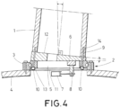
- the front face (11) of the moving ring (5) of the bearing (2) facing the interior of the hub (4) comprises recesses (13) parallel to the rear face (12) of the driving plate (6) positioned in contact with the blade (1), so that the bolts (9) are disposed parallel to the longitudinal direction of the blade (1) and the fixing nuts (10) rest properly in these recesses (13), as shown in figure 4 , where the bearing (2) is straight cylindrical.
- either the stretch of the holes (14) through the moving ring (5) of the bearing (2) forms an angle with the axis of the bearing (2) equal to the preconing angle, i.e., the angle between the rear face (12) and the front face (15) of the driving plate (6), as shown in figure 4 , or else the stretch of the holes (14) which pass through the moving ring (5) of the bearing (2) is parallel to the bearing axis (2) and has a diameter which defines a housing in which the bolts (9) are disposed parallel to the longitudinal direction of the blade (1), as shown in detail in figure 3 .
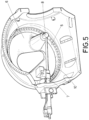
- the shaft (8) or ball joint system linking the actuator (7) with the driving plate (8) is located at least partially and preferably completely integrated into 5 said driving plate (6) as a protrusion of the driving plate, made up of a single piece.
- the function of said protrusion is to bring the surface of the plate at one end of the protrusion as close as possible to the point of attachment to the actuator (7). Consequently, the shaft (8) or ball joint system, if necessary, will be shorter and as a result of the reduction of the lever arm that it 10 has to bear, will also be of smaller section than in the case without protrusion.
- Bolted connections between the shaft (8) and the driving plate (6) which also required machining of 15 the mating surfaces of the two (6, 8) thereby increasing both the time and cost of the manufacturing process.
- the actuator (7) is attached to the hub (4) at a first end of said actuator (7), and joined to the protrusion on the driving plate (6) at a second end of said actuator (7).
- Said protrusion is located eccentrically on the driving plate in such a manner that the force required to rotate the blade is as small as possible.
- the shaft (8) or ball joint system connecting the actuator (7) to the driving plate (6) is partially integrated into the driving plate (6), the dimensions (section) of the shaft (8) or ball joint system are reduced, as when its length, determined by the distance between the driving plate (6) and the point of application of the force of the actuator (7) is reduced, then the momentum created in the section where it joins with the driving plate (6) is decreased by the reduction of the lever arm.
- the shaft (8) or ball joint system may be a cylindrical pin attached by thermal interference to the driving plate (6) and machined to allow clearance (rotation about the axis) between a crankpin of the actuator (7) and said shaft (8), the clearance being necessary to allow rotation of the bearing (2) by means of a linear actuator (7).
- the shaft (8) or ball joint system may be a cylindrical pin attached by thermal interference to the driving plate (6) and machined to allow clearance (rotation about the axis) between a crankpin of the actuator (7) and said shaft (8), the clearance being necessary to allow rotation of the bearing (2) by means of a linear actuator (7).
- fixing bolts (9) for the attachment of the driving plate (6) to the bearing (2) and to the blade (1).
- the attachment between the cylindrical pin and the protrusion (17) is adjacent to the crankpin of the actuator (7).
- this single part where the shaft (8) or axis-ball system is at least partially integrated into the driving plate (6), is made by casting.
- This manufacturing process allows the part to have complex geometries, such as, for example, the preconing angle or the joining into one part of two of the elements of the blade pitch system, such as the shaft (8) or axis-ball system and the driving plate (6), as described and shown in figures 5 and 6.
Landscapes
- Engineering & Computer Science (AREA)
- Life Sciences & Earth Sciences (AREA)
- Sustainable Development (AREA)
- Sustainable Energy (AREA)
- Chemical & Material Sciences (AREA)
- Combustion & Propulsion (AREA)
- Mechanical Engineering (AREA)
- General Engineering & Computer Science (AREA)
- Physics & Mathematics (AREA)
- Fluid Mechanics (AREA)
- Wind Motors (AREA)
Claims (9)
- Éolienne avec système de pas de pale, dans laquelle l'éolienne comprend :• au moins une pale (1),• un palier (2) avec un anneau fixe (3) relié à un moyeu (4) de l'éolienne et un anneau mobile (5),• une plaque d'entraînement (6) actionnée par un actionneur (7) relié au moyeu (4), dans laquelle la plaque d'entraînement (6) est disposée entre la pale (1) et le palier (2) et comprend une face arrière (12) disposée en contact avec la pale (1) et une face avant (15) disposée en contact avec une face arrière (16) de l'anneau mobile (5) du palier (2), dans laquelle la face arrière (12) de la plaque d'entraînement (6) est perpendiculaire à la direction longitudinale de la pale (1), et la face avant (15) de la plaque d'entraînement (6) est perpendiculaire à l'axe de palier (2), la face arrière (12) et la face avant (15) de la plaque d'entraînement (6) formant un angle autre que 0°, et• des moyens de liaison (9, 10) pour raccorder la pale (1), la plaque d'entraînement (6) et l'anneau mobile (5) du palier (2),dans laquelle l'actionneur (7) est relié à la face avant (15) de la plaque d'entraînement (6), au moyen d'un arbre (8) ou d'un système d'articulation à rotule raccordant l'actionneur (7) à la plaque d'entraînement (6) qui est au moins partiellement intégrée en tant que saillie sur ladite plaque d'entraînement (6), formant une seule pièce,et dans laquelle les moyens de liaison (9, 10) comprennent des boulons (9) agencés dans des orifices (14) passant à travers l'anneau mobile (5) du palier (2), la plaque d'entraînement (6) et la racine de la pale (1), les boulons (9) étant agencés parallèlement à la direction longitudinale de la pale (1).
- Éolienne avec système de pas de pale selon la revendication 1,
caractérisée en ce que les moyens de liaison (9, 10) comprennent en outre des écrous (10) qui permettent à la pale (1), à la plaque d'entraînement (9) et à l'anneau mobile (5) du palier (2) d'être fixés en place au moyen des boulons (9) agencés dans les orifices (14) passant à travers l'anneau mobile (5) du palier (2), la plaque d'entraînement (6) et la racine de la pale (1). - Éolienne avec système de pas de pale selon la revendication 2,
caractérisée en ce que le palier (2) comprend un anneau mobile (5) et un anneau fixe (3) avec une géométrie cylindrique droite de sorte qu'une face avant (11) de l'anneau mobile (5) du palier de pale (2) faisant face à l'intérieur du moyeu (4) soit perpendiculaire à l'axe de rotation du palier (2). - Éolienne avec système de pas de pale selon la revendication 3,
caractérisée en ce que la face avant (11) de l'anneau mobile (5) du palier (2) faisant face à l'intérieur du moyeu (4) comprend des renfoncements (13) parallèles à la face arrière (12) de la plaque d'entraînement (6) positionnés en contact avec la pale (1), où les écrous de fixation (10) sont en appui. - Éolienne avec système de pas de pale selon la revendication 2,
caractérisée en ce que la face arrière (12) de la plaque d'entraînement (6) et une face avant (11) de l'anneau mobile (5) du palier (2) faisant face à l'intérieur du moyeu (4) sont parallèles, de sorte que la face avant (11) de l'anneau mobile (5) du palier (2) soit perpendiculaire à l'axe longitudinal de la pale (1). - Éolienne avec système de pas de pale selon la revendication 5,
caractérisée en ce que les écrous de fixation (10) s'appuient sur la face avant (11) de l'anneau mobile (5) du palier (2). - Éolienne avec système de pas de pale selon l'une quelconque des revendications 1 à 6, caractérisée en ce qu'un tronçon des orifices (14) qui passent à travers l'anneau mobile (5) du palier (2) forme un angle avec l'axe du palier (2) égal à l'angle formé entre la face arrière (12) et la face avant (15) de la plaque d'entraînement (6).
- Éolienne avec système de pas de pale selon l'une quelconque des revendications 1 à 6, caractérisée en ce qu'un tronçon des orifices (14) qui passent à travers l'anneau mobile (5) du palier (2) est parallèle à l'axe de palier (2) et a un diamètre qui définit un logement dans lequel les boulons (9) sont agencés parallèlement à la direction longitudinale de la pale (1).
- Éolienne avec système de pas de pale selon l'une quelconque des revendications précédentes, caractérisée en ce que l'actionneur (7) est joint au moyeu (4) au niveau d'une première extrémité dudit actionneur (7) et joint à une extrémité de la saillie sur la plaque d'entraînement (6) au niveau d'une seconde extrémité de l'actionneur (7).
Applications Claiming Priority (1)
| Application Number | Priority Date | Filing Date | Title |
|---|---|---|---|
| ES201331871A ES2538417B1 (es) | 2013-12-19 | 2013-12-19 | Aerogenerador con sistema de cambio de paso de pala |
Publications (3)
| Publication Number | Publication Date |
|---|---|
| EP2886858A1 EP2886858A1 (fr) | 2015-06-24 |
| EP2886858B1 EP2886858B1 (fr) | 2018-11-28 |
| EP2886858B2 true EP2886858B2 (fr) | 2024-01-03 |
Family
ID=52101229
Family Applications (1)
| Application Number | Title | Priority Date | Filing Date |
|---|---|---|---|
| EP14198672.9A Active EP2886858B2 (fr) | 2013-12-19 | 2014-12-17 | Éolienne avec système de pas de pale |
Country Status (5)
| Country | Link |
|---|---|
| US (1) | US10018178B2 (fr) |
| EP (1) | EP2886858B2 (fr) |
| DK (1) | DK2886858T4 (fr) |
| ES (2) | ES2538417B1 (fr) |
| TR (1) | TR201902338T4 (fr) |
Families Citing this family (12)
| Publication number | Priority date | Publication date | Assignee | Title |
|---|---|---|---|---|
| EP3130797A1 (fr) | 2015-08-13 | 2017-02-15 | LM WP Patent Holding A/S | Pale d'éolienne dotée de brides d'extrémité |
| EP3168457B1 (fr) * | 2015-11-10 | 2021-06-16 | Nordex Energy Spain, S.A. | Éolienne avec pales avec un angle de conicité |
| DK3267033T3 (da) * | 2016-07-06 | 2019-07-01 | Siemens Gamesa Renewable Energy As | Vindmølle |
| CN110177932B (zh) * | 2017-01-19 | 2021-06-29 | 西门子歌美飒可再生能源公司 | 叶片安装装置 |
| EP3411592B1 (fr) | 2017-02-14 | 2019-06-26 | Shaikenov, Blok | Roue éolienne avec courbure de pale en coude |
| US11187206B2 (en) | 2017-10-17 | 2021-11-30 | Vestas Wind Systems A/S | Pitch system for a wind turbine |
| DE102018110925A1 (de) * | 2018-05-07 | 2019-11-07 | Liebherr-Components Biberach Gmbh | Stellantrieb zum Verstellen eines Großwälzlagers |
| CN109505733B (zh) * | 2019-01-23 | 2020-11-20 | 上海电气风电集团股份有限公司 | 一种应用于风电台风机组的叶片锁紧装置 |
| US11454219B2 (en) * | 2019-05-10 | 2022-09-27 | General Electric Company | Rotor assembly having a pitch bearing with a stiffener ring |
| CN111255631A (zh) * | 2020-02-15 | 2020-06-09 | 吴志华 | 一种风力发电机变桨装置 |
| CN114109903A (zh) * | 2020-08-25 | 2022-03-01 | 通用电气公司 | 叶片燕尾榫和保持设备 |
| CN113389818A (zh) * | 2021-06-16 | 2021-09-14 | 北京三力新能科技有限公司 | 一种回转支承使用的螺栓联接方式 |
Family Cites Families (18)
| Publication number | Priority date | Publication date | Assignee | Title |
|---|---|---|---|---|
| DE10201726B4 (de) * | 2002-01-18 | 2004-10-21 | Wobben, Aloys, Dipl.-Ing. | Windenergieanlage |
| DE102005026141B4 (de) | 2005-06-06 | 2019-07-25 | Imo Momentenlager Gmbh | Windkraftanlage mit einer Lagereinheit für ein langgestrecktes Rotorblatt |
| DE202006013519U1 (de) * | 2006-08-29 | 2006-12-21 | Euros Entwicklungsgesellschaft für Windkraftanlagen mbH | Windenergieanlage mit konusförmig angeordneten Rotorblättern |
| ES2308911B1 (es) * | 2006-12-05 | 2009-10-27 | GAMESA INNOVATION & TECHNOLOGY, S.L. | Sistema de cambio de paso variable accionado electricamente. |
| DE102007008167C5 (de) * | 2007-02-14 | 2016-07-07 | Nordex Energy Gmbh | Windenergieanlage mit einer Rotornabe |
| EP2078851A1 (fr) * | 2008-01-14 | 2009-07-15 | Lm Glasfiber A/S | Pale d'éolienne et assemblage de moyeu |
| ES2379618B1 (es) * | 2009-12-16 | 2013-03-26 | Acciona Windpower, S.A. | Rodamiento de pala de aerogenerador y aerogenerador que hace uso del mismo. |
| DE102010010639A1 (de) | 2010-03-09 | 2011-09-15 | Schaeffler Technologies Gmbh & Co. Kg | Drehverbindung eines Rotorblattes mit der Rotornabe einer Windkraftanlage |
| US9121385B2 (en) * | 2010-11-26 | 2015-09-01 | Vestas Wind Systems A/S | Wind turbine and a method for pitching a blade of a wind turbine |
| DE102011000769A1 (de) * | 2011-02-16 | 2012-08-16 | Rothe Erde Gmbh | Axial-Radialwälzlager, insbesondere für die Lagerung von Rotorblättern an einer Windkraftanlage |
| IN2014DN05667A (fr) | 2011-12-21 | 2015-04-03 | Vestas Wind Sys As | |
| US9239040B2 (en) * | 2012-02-16 | 2016-01-19 | General Electric Company | Root end assembly configuration for a wind turbine rotor blade and associated forming methods |
| WO2013176723A1 (fr) | 2012-05-22 | 2013-11-28 | United Technologies Corporation | Atténuation de charge d'éolienne |
| US9074581B2 (en) | 2012-06-12 | 2015-07-07 | General Electric Company | Cone angle insert for wind turbine rotor |
| US9109578B2 (en) | 2012-06-12 | 2015-08-18 | General Electric Company | Root extender for a wind turbine rotor blade |
| EP2679805B1 (fr) * | 2012-06-29 | 2015-02-18 | General Electric Company | Insert de l'angle de cône pour rotor de turbine éolienne |
| US9951815B2 (en) | 2013-06-27 | 2018-04-24 | General Electric Company | Pitch bearing assembly with stiffener |
| DK177926B1 (en) | 2013-12-20 | 2015-01-12 | Fritz Schur Energy As | Pitch actuator arrangement |
-
2013
- 2013-12-19 ES ES201331871A patent/ES2538417B1/es not_active Expired - Fee Related
-
2014
- 2014-12-17 TR TR2019/02338T patent/TR201902338T4/tr unknown
- 2014-12-17 ES ES14198672T patent/ES2714098T3/es active Active
- 2014-12-17 EP EP14198672.9A patent/EP2886858B2/fr active Active
- 2014-12-17 DK DK14198672.9T patent/DK2886858T4/da active
- 2014-12-19 US US14/576,609 patent/US10018178B2/en active Active
Also Published As
| Publication number | Publication date |
|---|---|
| TR201902338T4 (tr) | 2019-03-21 |
| EP2886858B1 (fr) | 2018-11-28 |
| ES2714098T3 (es) | 2019-05-27 |
| DK2886858T4 (da) | 2024-01-22 |
| ES2538417A1 (es) | 2015-06-19 |
| ES2538417B1 (es) | 2016-04-20 |
| US20150176567A1 (en) | 2015-06-25 |
| EP2886858A1 (fr) | 2015-06-24 |
| DK2886858T3 (en) | 2019-03-18 |
| US10018178B2 (en) | 2018-07-10 |
Similar Documents
| Publication | Publication Date | Title |
|---|---|---|
| EP2886858B2 (fr) | Éolienne avec système de pas de pale | |
| US20170268482A1 (en) | Rotor blade for wind turbines | |
| AU2007251569B2 (en) | Rotor blade for a wind energy installation | |
| EP3707373B1 (fr) | Joints de pale d'éolienne à connecteurs flottants | |
| EP2497878B1 (fr) | Bride et système d'énergie éolienne | |
| EP2336553B1 (fr) | Eolienne comprenant une pale d'éolienne et roulement de pale d'éolienne | |
| US20140072402A1 (en) | Wind turbine | |
| EP2541049B1 (fr) | Ensemble de moyeu destiné à être utilisé avec une turbine éolienne et son procédé de fabrication | |
| KR20130095656A (ko) | 풍력 터빈 | |
| EP3219979A1 (fr) | Raccord boulonné pour segments de pale de rotor | |
| CN104047812A (zh) | 具有支撑元件的轴承和支撑轴承的第一环的方法 | |
| US9175667B2 (en) | Fastening system for wind turbines and corresponding installation methods | |
| EP3112669B1 (fr) | Arrangement de palier pour la pale d'une éolienne | |
| EP2405131B1 (fr) | Dispositif de commande pour turbine éolienne | |
| JP4574442B2 (ja) | 水平軸風車のブレード | |
| KR102053892B1 (ko) | 터빈용 로터 블레이드 | |
| EP3839246B1 (fr) | Ensemble base d'une pale pour éolienne, pale d'éolienne et éolienne | |
| EP3168457B1 (fr) | Éolienne avec pales avec un angle de conicité | |
| US11333200B2 (en) | Method for manufacturing a pitch bearing or a yaw bearing of a wind turbine via additive manufacturing | |
| EP4077916B1 (fr) | Une turbine éolienne avec un entraînement en position de lacet | |
| IT202000023056A1 (it) | Steering rod per turbocompressori e metodo per realizzarla |
Legal Events
| Date | Code | Title | Description |
|---|---|---|---|
| PUAI | Public reference made under article 153(3) epc to a published international application that has entered the european phase |
Free format text: ORIGINAL CODE: 0009012 |
|
| 17P | Request for examination filed |
Effective date: 20141217 |
|
| AK | Designated contracting states |
Kind code of ref document: A1 Designated state(s): AL AT BE BG CH CY CZ DE DK EE ES FI FR GB GR HR HU IE IS IT LI LT LU LV MC MK MT NL NO PL PT RO RS SE SI SK SM TR |
|
| AX | Request for extension of the european patent |
Extension state: BA ME |
|
| R17P | Request for examination filed (corrected) |
Effective date: 20151223 |
|
| RBV | Designated contracting states (corrected) |
Designated state(s): AL AT BE BG CH CY CZ DE DK EE ES FI FR GB GR HR HU IE IS IT LI LT LU LV MC MK MT NL NO PL PT RO RS SE SI SK SM TR |
|
| STAA | Information on the status of an ep patent application or granted ep patent |
Free format text: STATUS: EXAMINATION IS IN PROGRESS |
|
| 17Q | First examination report despatched |
Effective date: 20180118 |
|
| REG | Reference to a national code |
Ref country code: DE Ref legal event code: R079 Ref document number: 602014036854 Country of ref document: DE Free format text: PREVIOUS MAIN CLASS: F03D0011000000 Ipc: F03D0001060000 |
|
| GRAP | Despatch of communication of intention to grant a patent |
Free format text: ORIGINAL CODE: EPIDOSNIGR1 |
|
| STAA | Information on the status of an ep patent application or granted ep patent |
Free format text: STATUS: GRANT OF PATENT IS INTENDED |
|
| RIC1 | Information provided on ipc code assigned before grant |
Ipc: F03D 1/06 20060101AFI20180906BHEP Ipc: F03D 80/70 20160101ALI20180906BHEP |
|
| GRAS | Grant fee paid |
Free format text: ORIGINAL CODE: EPIDOSNIGR3 |
|
| GRAA | (expected) grant |
Free format text: ORIGINAL CODE: 0009210 |
|
| STAA | Information on the status of an ep patent application or granted ep patent |
Free format text: STATUS: THE PATENT HAS BEEN GRANTED |
|
| INTG | Intention to grant announced |
Effective date: 20181008 |
|
| AK | Designated contracting states |
Kind code of ref document: B1 Designated state(s): AL AT BE BG CH CY CZ DE DK EE ES FI FR GB GR HR HU IE IS IT LI LT LU LV MC MK MT NL NO PL PT RO RS SE SI SK SM TR |
|
| REG | Reference to a national code |
Ref country code: CH Ref legal event code: EP |
|
| REG | Reference to a national code |
Ref country code: AT Ref legal event code: REF Ref document number: 1070555 Country of ref document: AT Kind code of ref document: T Effective date: 20181215 |
|
| REG | Reference to a national code |
Ref country code: DE Ref legal event code: R096 Ref document number: 602014036854 Country of ref document: DE |
|
| REG | Reference to a national code |
Ref country code: IE Ref legal event code: FG4D |
|
| RAP2 | Party data changed (patent owner data changed or rights of a patent transferred) |
Owner name: NORDEX ENERGY SPAIN, S.A.U. |
|
| REG | Reference to a national code |
Ref country code: DE Ref legal event code: R081 Ref document number: 602014036854 Country of ref document: DE Owner name: NORDEX ENERGY SPAIN, S.A.U., BARASOAIN, ES Free format text: FORMER OWNER: ACCIONA WINDPOWER S.A., SARRIGUREN, NAVARRA, ES |
|
| REG | Reference to a national code |
Ref country code: DK Ref legal event code: T3 Effective date: 20190311 |
|
| REG | Reference to a national code |
Ref country code: SE Ref legal event code: TRGR |
|
| REG | Reference to a national code |
Ref country code: NL Ref legal event code: MP Effective date: 20181128 |
|
| REG | Reference to a national code |
Ref country code: LT Ref legal event code: MG4D |
|
| REG | Reference to a national code |
Ref country code: AT Ref legal event code: MK05 Ref document number: 1070555 Country of ref document: AT Kind code of ref document: T Effective date: 20181128 |
|
| PG25 | Lapsed in a contracting state [announced via postgrant information from national office to epo] |
Ref country code: HR Free format text: LAPSE BECAUSE OF FAILURE TO SUBMIT A TRANSLATION OF THE DESCRIPTION OR TO PAY THE FEE WITHIN THE PRESCRIBED TIME-LIMIT Effective date: 20181128 Ref country code: LV Free format text: LAPSE BECAUSE OF FAILURE TO SUBMIT A TRANSLATION OF THE DESCRIPTION OR TO PAY THE FEE WITHIN THE PRESCRIBED TIME-LIMIT Effective date: 20181128 Ref country code: LT Free format text: LAPSE BECAUSE OF FAILURE TO SUBMIT A TRANSLATION OF THE DESCRIPTION OR TO PAY THE FEE WITHIN THE PRESCRIBED TIME-LIMIT Effective date: 20181128 Ref country code: BG Free format text: LAPSE BECAUSE OF FAILURE TO SUBMIT A TRANSLATION OF THE DESCRIPTION OR TO PAY THE FEE WITHIN THE PRESCRIBED TIME-LIMIT Effective date: 20190228 Ref country code: IS Free format text: LAPSE BECAUSE OF FAILURE TO SUBMIT A TRANSLATION OF THE DESCRIPTION OR TO PAY THE FEE WITHIN THE PRESCRIBED TIME-LIMIT Effective date: 20190328 Ref country code: AT Free format text: LAPSE BECAUSE OF FAILURE TO SUBMIT A TRANSLATION OF THE DESCRIPTION OR TO PAY THE FEE WITHIN THE PRESCRIBED TIME-LIMIT Effective date: 20181128 |
|
| REG | Reference to a national code |
Ref country code: NO Ref legal event code: T2 Effective date: 20181128 |
|
| REG | Reference to a national code |
Ref country code: ES Ref legal event code: FG2A Ref document number: 2714098 Country of ref document: ES Kind code of ref document: T3 Effective date: 20190527 |
|
| PG25 | Lapsed in a contracting state [announced via postgrant information from national office to epo] |
Ref country code: PT Free format text: LAPSE BECAUSE OF FAILURE TO SUBMIT A TRANSLATION OF THE DESCRIPTION OR TO PAY THE FEE WITHIN THE PRESCRIBED TIME-LIMIT Effective date: 20190328 Ref country code: GR Free format text: LAPSE BECAUSE OF FAILURE TO SUBMIT A TRANSLATION OF THE DESCRIPTION OR TO PAY THE FEE WITHIN THE PRESCRIBED TIME-LIMIT Effective date: 20190301 Ref country code: AL Free format text: LAPSE BECAUSE OF FAILURE TO SUBMIT A TRANSLATION OF THE DESCRIPTION OR TO PAY THE FEE WITHIN THE PRESCRIBED TIME-LIMIT Effective date: 20181128 Ref country code: RS Free format text: LAPSE BECAUSE OF FAILURE TO SUBMIT A TRANSLATION OF THE DESCRIPTION OR TO PAY THE FEE WITHIN THE PRESCRIBED TIME-LIMIT Effective date: 20181128 |
|
| PG25 | Lapsed in a contracting state [announced via postgrant information from national office to epo] |
Ref country code: NL Free format text: LAPSE BECAUSE OF FAILURE TO SUBMIT A TRANSLATION OF THE DESCRIPTION OR TO PAY THE FEE WITHIN THE PRESCRIBED TIME-LIMIT Effective date: 20181128 |
|
| PG25 | Lapsed in a contracting state [announced via postgrant information from national office to epo] |
Ref country code: IT Free format text: LAPSE BECAUSE OF FAILURE TO SUBMIT A TRANSLATION OF THE DESCRIPTION OR TO PAY THE FEE WITHIN THE PRESCRIBED TIME-LIMIT Effective date: 20181128 Ref country code: CZ Free format text: LAPSE BECAUSE OF FAILURE TO SUBMIT A TRANSLATION OF THE DESCRIPTION OR TO PAY THE FEE WITHIN THE PRESCRIBED TIME-LIMIT Effective date: 20181128 Ref country code: PL Free format text: LAPSE BECAUSE OF FAILURE TO SUBMIT A TRANSLATION OF THE DESCRIPTION OR TO PAY THE FEE WITHIN THE PRESCRIBED TIME-LIMIT Effective date: 20181128 |
|
| REG | Reference to a national code |
Ref country code: CH Ref legal event code: PL |
|
| REG | Reference to a national code |
Ref country code: DE Ref legal event code: R026 Ref document number: 602014036854 Country of ref document: DE |
|
| PLBI | Opposition filed |
Free format text: ORIGINAL CODE: 0009260 |
|
| PG25 | Lapsed in a contracting state [announced via postgrant information from national office to epo] |
Ref country code: MC Free format text: LAPSE BECAUSE OF FAILURE TO SUBMIT A TRANSLATION OF THE DESCRIPTION OR TO PAY THE FEE WITHIN THE PRESCRIBED TIME-LIMIT Effective date: 20181128 Ref country code: SK Free format text: LAPSE BECAUSE OF FAILURE TO SUBMIT A TRANSLATION OF THE DESCRIPTION OR TO PAY THE FEE WITHIN THE PRESCRIBED TIME-LIMIT Effective date: 20181128 Ref country code: LU Free format text: LAPSE BECAUSE OF NON-PAYMENT OF DUE FEES Effective date: 20181217 Ref country code: RO Free format text: LAPSE BECAUSE OF FAILURE TO SUBMIT A TRANSLATION OF THE DESCRIPTION OR TO PAY THE FEE WITHIN THE PRESCRIBED TIME-LIMIT Effective date: 20181128 Ref country code: EE Free format text: LAPSE BECAUSE OF FAILURE TO SUBMIT A TRANSLATION OF THE DESCRIPTION OR TO PAY THE FEE WITHIN THE PRESCRIBED TIME-LIMIT Effective date: 20181128 Ref country code: SM Free format text: LAPSE BECAUSE OF FAILURE TO SUBMIT A TRANSLATION OF THE DESCRIPTION OR TO PAY THE FEE WITHIN THE PRESCRIBED TIME-LIMIT Effective date: 20181128 |
|
| REG | Reference to a national code |
Ref country code: IE Ref legal event code: MM4A |
|
| 26 | Opposition filed |
Opponent name: SIEMENS GAMESA RENEWABLE ENERGY GMBH & CO. KG Effective date: 20190814 |
|
| REG | Reference to a national code |
Ref country code: BE Ref legal event code: MM Effective date: 20181231 |
|
| PLAX | Notice of opposition and request to file observation + time limit sent |
Free format text: ORIGINAL CODE: EPIDOSNOBS2 |
|
| PG25 | Lapsed in a contracting state [announced via postgrant information from national office to epo] |
Ref country code: SI Free format text: LAPSE BECAUSE OF FAILURE TO SUBMIT A TRANSLATION OF THE DESCRIPTION OR TO PAY THE FEE WITHIN THE PRESCRIBED TIME-LIMIT Effective date: 20181128 Ref country code: IE Free format text: LAPSE BECAUSE OF NON-PAYMENT OF DUE FEES Effective date: 20181217 |
|
| PG25 | Lapsed in a contracting state [announced via postgrant information from national office to epo] |
Ref country code: BE Free format text: LAPSE BECAUSE OF NON-PAYMENT OF DUE FEES Effective date: 20181231 |
|
| PG25 | Lapsed in a contracting state [announced via postgrant information from national office to epo] |
Ref country code: CH Free format text: LAPSE BECAUSE OF NON-PAYMENT OF DUE FEES Effective date: 20181231 Ref country code: LI Free format text: LAPSE BECAUSE OF NON-PAYMENT OF DUE FEES Effective date: 20181231 |
|
| PG25 | Lapsed in a contracting state [announced via postgrant information from national office to epo] |
Ref country code: MT Free format text: LAPSE BECAUSE OF NON-PAYMENT OF DUE FEES Effective date: 20181217 |
|
| PGFP | Annual fee paid to national office [announced via postgrant information from national office to epo] |
Ref country code: FI Payment date: 20191227 Year of fee payment: 6 |
|
| PLBB | Reply of patent proprietor to notice(s) of opposition received |
Free format text: ORIGINAL CODE: EPIDOSNOBS3 |
|
| PGFP | Annual fee paid to national office [announced via postgrant information from national office to epo] |
Ref country code: NO Payment date: 20191227 Year of fee payment: 6 |
|
| PG25 | Lapsed in a contracting state [announced via postgrant information from national office to epo] |
Ref country code: MK Free format text: LAPSE BECAUSE OF NON-PAYMENT OF DUE FEES Effective date: 20181128 Ref country code: HU Free format text: LAPSE BECAUSE OF FAILURE TO SUBMIT A TRANSLATION OF THE DESCRIPTION OR TO PAY THE FEE WITHIN THE PRESCRIBED TIME-LIMIT; INVALID AB INITIO Effective date: 20141217 Ref country code: CY Free format text: LAPSE BECAUSE OF FAILURE TO SUBMIT A TRANSLATION OF THE DESCRIPTION OR TO PAY THE FEE WITHIN THE PRESCRIBED TIME-LIMIT Effective date: 20181128 |
|
| PGFP | Annual fee paid to national office [announced via postgrant information from national office to epo] |
Ref country code: TR Payment date: 20200214 Year of fee payment: 6 |
|
| REG | Reference to a national code |
Ref country code: FI Ref legal event code: MAE |
|
| REG | Reference to a national code |
Ref country code: NO Ref legal event code: MMEP |
|
| PG25 | Lapsed in a contracting state [announced via postgrant information from national office to epo] |
Ref country code: FI Free format text: LAPSE BECAUSE OF NON-PAYMENT OF DUE FEES Effective date: 20201217 |
|
| APAH | Appeal reference modified |
Free format text: ORIGINAL CODE: EPIDOSCREFNO |
|
| APBM | Appeal reference recorded |
Free format text: ORIGINAL CODE: EPIDOSNREFNO |
|
| APBP | Date of receipt of notice of appeal recorded |
Free format text: ORIGINAL CODE: EPIDOSNNOA2O |
|
| APBM | Appeal reference recorded |
Free format text: ORIGINAL CODE: EPIDOSNREFNO |
|
| APBP | Date of receipt of notice of appeal recorded |
Free format text: ORIGINAL CODE: EPIDOSNNOA2O |
|
| APBQ | Date of receipt of statement of grounds of appeal recorded |
Free format text: ORIGINAL CODE: EPIDOSNNOA3O |
|
| PG25 | Lapsed in a contracting state [announced via postgrant information from national office to epo] |
Ref country code: NO Free format text: LAPSE BECAUSE OF NON-PAYMENT OF DUE FEES Effective date: 20201231 |
|
| APBQ | Date of receipt of statement of grounds of appeal recorded |
Free format text: ORIGINAL CODE: EPIDOSNNOA3O |
|
| PG25 | Lapsed in a contracting state [announced via postgrant information from national office to epo] |
Ref country code: TR Free format text: LAPSE BECAUSE OF NON-PAYMENT OF DUE FEES Effective date: 20201217 |
|
| PLAB | Opposition data, opponent's data or that of the opponent's representative modified |
Free format text: ORIGINAL CODE: 0009299OPPO |
|
| R26 | Opposition filed (corrected) |
Opponent name: SIEMENS GAMESA RENEWABLE ENERGY GMBH & CO. KG Effective date: 20190814 |
|
| APBU | Appeal procedure closed |
Free format text: ORIGINAL CODE: EPIDOSNNOA9O |
|
| P01 | Opt-out of the competence of the unified patent court (upc) registered |
Effective date: 20230530 |
|
| PUAH | Patent maintained in amended form |
Free format text: ORIGINAL CODE: 0009272 |
|
| STAA | Information on the status of an ep patent application or granted ep patent |
Free format text: STATUS: PATENT MAINTAINED AS AMENDED |
|
| REG | Reference to a national code |
Ref country code: DE Ref legal event code: R082 Ref document number: 602014036854 Country of ref document: DE |
|
| 27A | Patent maintained in amended form |
Effective date: 20240103 |
|
| AK | Designated contracting states |
Kind code of ref document: B2 Designated state(s): AL AT BE BG CH CY CZ DE DK EE ES FI FR GB GR HR HU IE IS IT LI LT LU LV MC MK MT NL NO PL PT RO RS SE SI SK SM TR |
|
| REG | Reference to a national code |
Ref country code: DE Ref legal event code: R102 Ref document number: 602014036854 Country of ref document: DE |
|
| PGFP | Annual fee paid to national office [announced via postgrant information from national office to epo] |
Ref country code: GB Payment date: 20231220 Year of fee payment: 10 |
|
| REG | Reference to a national code |
Ref country code: DK Ref legal event code: T4 Effective date: 20240119 |
|
| PGFP | Annual fee paid to national office [announced via postgrant information from national office to epo] |
Ref country code: SE Payment date: 20231219 Year of fee payment: 10 Ref country code: FR Payment date: 20231220 Year of fee payment: 10 Ref country code: DK Payment date: 20231219 Year of fee payment: 10 Ref country code: DE Payment date: 20231214 Year of fee payment: 10 |
|
| REG | Reference to a national code |
Ref country code: SE Ref legal event code: RPEO |
|
| PGFP | Annual fee paid to national office [announced via postgrant information from national office to epo] |
Ref country code: ES Payment date: 20240118 Year of fee payment: 10 |