EP2886846A1 - Injector water intrusion seal with blow out volume - Google Patents
Injector water intrusion seal with blow out volume Download PDFInfo
- Publication number
- EP2886846A1 EP2886846A1 EP14189320.6A EP14189320A EP2886846A1 EP 2886846 A1 EP2886846 A1 EP 2886846A1 EP 14189320 A EP14189320 A EP 14189320A EP 2886846 A1 EP2886846 A1 EP 2886846A1
- Authority
- EP
- European Patent Office
- Prior art keywords
- seal
- injector
- housing
- inlet
- groove
- Prior art date
- Legal status (The legal status is an assumption and is not a legal conclusion. Google has not performed a legal analysis and makes no representation as to the accuracy of the status listed.)
- Granted
Links
Images



Classifications
-
- F—MECHANICAL ENGINEERING; LIGHTING; HEATING; WEAPONS; BLASTING
- F01—MACHINES OR ENGINES IN GENERAL; ENGINE PLANTS IN GENERAL; STEAM ENGINES
- F01N—GAS-FLOW SILENCERS OR EXHAUST APPARATUS FOR MACHINES OR ENGINES IN GENERAL; GAS-FLOW SILENCERS OR EXHAUST APPARATUS FOR INTERNAL-COMBUSTION ENGINES
- F01N3/00—Exhaust or silencing apparatus having means for purifying, rendering innocuous, or otherwise treating exhaust
- F01N3/08—Exhaust or silencing apparatus having means for purifying, rendering innocuous, or otherwise treating exhaust for rendering innocuous
- F01N3/10—Exhaust or silencing apparatus having means for purifying, rendering innocuous, or otherwise treating exhaust for rendering innocuous by thermal or catalytic conversion of noxious components of exhaust
- F01N3/18—Exhaust or silencing apparatus having means for purifying, rendering innocuous, or otherwise treating exhaust for rendering innocuous by thermal or catalytic conversion of noxious components of exhaust characterised by methods of operation; Control
- F01N3/20—Exhaust or silencing apparatus having means for purifying, rendering innocuous, or otherwise treating exhaust for rendering innocuous by thermal or catalytic conversion of noxious components of exhaust characterised by methods of operation; Control specially adapted for catalytic conversion
- F01N3/206—Adding periodically or continuously substances to exhaust gases for promoting purification, e.g. catalytic material in liquid form, NOx reducing agents
- F01N3/2066—Selective catalytic reduction [SCR]
-
- F—MECHANICAL ENGINEERING; LIGHTING; HEATING; WEAPONS; BLASTING
- F02—COMBUSTION ENGINES; HOT-GAS OR COMBUSTION-PRODUCT ENGINE PLANTS
- F02M—SUPPLYING COMBUSTION ENGINES IN GENERAL WITH COMBUSTIBLE MIXTURES OR CONSTITUENTS THEREOF
- F02M65/00—Testing fuel-injection apparatus, e.g. testing injection timing ; Cleaning of fuel-injection apparatus
- F02M65/006—Measuring or detecting fuel leakage of fuel injection apparatus
-
- F—MECHANICAL ENGINEERING; LIGHTING; HEATING; WEAPONS; BLASTING
- F02—COMBUSTION ENGINES; HOT-GAS OR COMBUSTION-PRODUCT ENGINE PLANTS
- F02M—SUPPLYING COMBUSTION ENGINES IN GENERAL WITH COMBUSTIBLE MIXTURES OR CONSTITUENTS THEREOF
- F02M55/00—Fuel-injection apparatus characterised by their fuel conduits or their venting means; Arrangements of conduits between fuel tank and pump F02M37/00
- F02M55/004—Joints; Sealings
- F02M55/005—Joints; Sealings for high pressure conduits, e.g. connected to pump outlet or to injector inlet
-
- F—MECHANICAL ENGINEERING; LIGHTING; HEATING; WEAPONS; BLASTING
- F02—COMBUSTION ENGINES; HOT-GAS OR COMBUSTION-PRODUCT ENGINE PLANTS
- F02M—SUPPLYING COMBUSTION ENGINES IN GENERAL WITH COMBUSTIBLE MIXTURES OR CONSTITUENTS THEREOF
- F02M61/00—Fuel-injectors not provided for in groups F02M39/00 - F02M57/00 or F02M67/00
- F02M61/16—Details not provided for in, or of interest apart from, the apparatus of groups F02M61/02 - F02M61/14
- F02M61/168—Assembling; Disassembling; Manufacturing; Adjusting
-
- F—MECHANICAL ENGINEERING; LIGHTING; HEATING; WEAPONS; BLASTING
- F01—MACHINES OR ENGINES IN GENERAL; ENGINE PLANTS IN GENERAL; STEAM ENGINES
- F01N—GAS-FLOW SILENCERS OR EXHAUST APPARATUS FOR MACHINES OR ENGINES IN GENERAL; GAS-FLOW SILENCERS OR EXHAUST APPARATUS FOR INTERNAL-COMBUSTION ENGINES
- F01N2610/00—Adding substances to exhaust gases
- F01N2610/02—Adding substances to exhaust gases the substance being ammonia or urea
-
- F—MECHANICAL ENGINEERING; LIGHTING; HEATING; WEAPONS; BLASTING
- F01—MACHINES OR ENGINES IN GENERAL; ENGINE PLANTS IN GENERAL; STEAM ENGINES
- F01N—GAS-FLOW SILENCERS OR EXHAUST APPARATUS FOR MACHINES OR ENGINES IN GENERAL; GAS-FLOW SILENCERS OR EXHAUST APPARATUS FOR INTERNAL-COMBUSTION ENGINES
- F01N2610/00—Adding substances to exhaust gases
- F01N2610/14—Arrangements for the supply of substances, e.g. conduits
- F01N2610/1453—Sprayers or atomisers; Arrangement thereof in the exhaust apparatus
-
- F—MECHANICAL ENGINEERING; LIGHTING; HEATING; WEAPONS; BLASTING
- F02—COMBUSTION ENGINES; HOT-GAS OR COMBUSTION-PRODUCT ENGINE PLANTS
- F02M—SUPPLYING COMBUSTION ENGINES IN GENERAL WITH COMBUSTIBLE MIXTURES OR CONSTITUENTS THEREOF
- F02M2200/00—Details of fuel-injection apparatus, not otherwise provided for
- F02M2200/16—Sealing of fuel injection apparatus not otherwise provided for
-
- Y—GENERAL TAGGING OF NEW TECHNOLOGICAL DEVELOPMENTS; GENERAL TAGGING OF CROSS-SECTIONAL TECHNOLOGIES SPANNING OVER SEVERAL SECTIONS OF THE IPC; TECHNICAL SUBJECTS COVERED BY FORMER USPC CROSS-REFERENCE ART COLLECTIONS [XRACs] AND DIGESTS
- Y10—TECHNICAL SUBJECTS COVERED BY FORMER USPC
- Y10T—TECHNICAL SUBJECTS COVERED BY FORMER US CLASSIFICATION
- Y10T29/00—Metal working
- Y10T29/49—Method of mechanical manufacture
- Y10T29/494—Fluidic or fluid actuated device making
Definitions
- the invention relates generally to a secondary seal used for preventing liquid from entering an injector, and in more particular, to blow-out volume that can receive a portion of a secondary seal.
- a fluid injector for use as a Reductant Delivery Unit (RDU) in a Selective Catalytic Reduction (SCR) system includes a primary O-ring 12 to seal urea being introduced into the injector 10 and to prevent liquid (e.g., water) ingress into the interior 16 of the injector 10.
- liquid e.g., water
- the primary seal 12 can ingress through the injector shield 14 and migrate below the primary O-ring 12 and enter the interior 16 of the injector 10 (between housing 26 and inlet tube 30).
- Such water ingress below the primary O-ring 12 can cause corrosion and or electrical short circuiting.
- Applicant added a secondary seal or O-ring 18 to eliminate water intrusion that may migrate below the primary O-ring 12.
- the secondary seal was found to prevent effective testing of the primary O-ring 12. Failure of the primary O-ring 12 would force AUS32 (urea, indicated by arrows in FIG. 3 ) into the interior 16 of the injector 10, leading to premature injector failure.
- a fluid injector that includes a housing and an inlet tube having a portion received in the housing.
- the inlet tube has an opened end for receiving fluid from an inlet of the injector.
- a primary seal is disposed about a portion of the inlet tube so as to create a seal between surfaces of the housing, the inlet tube, and the inlet of the injector.
- a groove is defined in a periphery of the housing and a secondary seal is disposed in the groove and defining a seal between the housing and a portion of the inlet of the injector.
- a recessed portion is defined in the housing and is in communication with the groove so that due to the recessed portion, an entirety of the secondary seal is not supported by the groove.
- the recessed portion defines a blow-out volume such that when the primary seal is leak tested by forcing pressurized air through the inlet of the injector, an indication of a leak of the primary seal can be detected when the pressurized air moves past the primary seal and forces a portion of the secondary seal to an unsealed position into the blow-out volume.
- a method seals a fluid injector.
- the injector includes a housing and an inlet tube having a portion received in the housing.
- the inlet tube has an opened end for receiving fluid from an inlet of the injector.
- the method provides a primary seal disposed about a portion of the inlet tube so as to create a first seal between surfaces of the housing, the inlet tube, and the inlet of the injector.
- a secondary seal defines a second seal between the housing and a portion of the inlet of the injector.
- the method ensures that the second seal can be forced by the pressurized air into an unsealed positon, thereby indicating a leak of the primary seal.
- a fluid injector is shown, generally indicated at 10', in accordance with an embodiment.
- the injector 10' is constructed and arranged as a Reductant Delivery Unit (RDU) for use in a Selective Catalytic Reduction (SCR) system.
- RDU Reductant Delivery Unit
- SCR Selective Catalytic Reduction
- the injector 10' includes an inlet cup assembly having an inlet cup 20 coupled to a cup tube 22 defining an inlet of the injector 10'.
- the cup tube 22 is constructed and arranged to be connected to a source of fluid such as urea for introduction into the injector 10'.
- the inlet cup 20 is connected to a shield 14, and the shield 24 substantially surrounds a housing 26, which includes an electrical connector 28.
- FIG. 4 does not show the inlet cup assembly or the shield 14 so that components there-under can be seen clearly.
- a portion of an inlet tube 30 is disposed within the housing 26.
- the inlet tube 30 has an open end 31 for receiving fluid from the inlet cup assembly (injector inlet) that will be ejected from the injector 10'.
- a primary seal such as an elastomer O-ring 12 is disposed about a periphery of an upper portion of the cylindrical inlet tube 30 adjacent to the housing 26 to prevent liquid (e.g., water) ingress into the interior 16 of the injector 10'.
- the primary seal 12 also seals urea from migrating past the inlet cup 20 and between the housing 26 and the inlet tube 30.
- the primary seal 12 thus provides a seal between the inner surface 32 of the inlet cup 20, an outer surface 34 of the inlet tube 30 and an upper surface 36 of the housing 26.
- a secondary seal 18 such as an elastomer O-ring is disposed in an annular groove 38 formed in a periphery of the housing 26, generally adjacent to the primary seal 12.
- the secondary seal 18 defines a seal between the housing 26 and the inlet cup 20 that prevents water leakage into the interior 16 that may enter through the shield 14.
- Also formed as part of the housing 26 and in communication with the groove 38 is a recessed portion 40 defining blow-out volume, generally indicated at 42. The recessed portion 40 extends axially from the groove 38.
- the groove 38 extends less than 360° about the periphery of the housing 26, leaving a small portion of the secondary seal 18 unsupported.
- the recess portion 40 can be molded into the groove 38 upon molding the housing 26. The function of the blow-out volume 42 will be explained below.
- the primary seal 12 is tested to make sure it is functioning properly.
- pressurized air P is forced into the cup tube 22 (the lower end of the injector 10 is also sealed to allow pressure to build inside the injector 10), such that the primary seal 12 is exposed to the pressurized air. If the primary seal 12 is damaged or is functioning improperly, the pressurized air moves past by the primary seal 12, and the secondary seal 18 is then exposed to the pressurized air, causing a portion of the secondary seal 18 to move to an unsealed position by extruding into the blow-out volume 42 of the recessed portion 40.
- the secondary seal 18 moves to an unsealed area, a leak due to a faulty primary seal 12 can be detected.
- the secondary seal 18 must be flexible enough to extrude into the blow-out volume 42, but be firm enough to remain in position during assembly and during normal use.
- the recessed portion 38 is generally U-shaped, and has a maximum width W of 3.0 mm. However, it is within the scope of the invention that other shapes and widths may be used.
- a small groove 44 is in communication with the recessed portion 40 and the blow-out volume 42.
- the groove permits the secondary seal 18 to move less before releasing any pressure during leak testing.
- This groove 44 is necessary if the injector 10' is inserted deep into the inlet cup 20 since the secondary seal 18 would not blow-out, giving false leak measurements.
- the arrows in FIG. 9 show an air path around the secondary seal 18 using the groove 44 when the secondary seal 18 moves to an unsealed position upon testing the primary seal 12.
- the secondary seal 18 provides further sealing of the interior 16 of the injector 10' in the event water gets past the primary seal 12.
- the blow-out volume 42, receiving a portion of the secondary seal 18, allows the primary seal 12 to be leak tested thereby ensuring the integrity of the primary seal 12 and preventing urea from entering into the interior 16 of the injector 10'.
Landscapes
- Engineering & Computer Science (AREA)
- Chemical & Material Sciences (AREA)
- General Engineering & Computer Science (AREA)
- Combustion & Propulsion (AREA)
- Mechanical Engineering (AREA)
- Chemical Kinetics & Catalysis (AREA)
- Manufacturing & Machinery (AREA)
- Health & Medical Sciences (AREA)
- Toxicology (AREA)
- Exhaust Gas After Treatment (AREA)
- Examining Or Testing Airtightness (AREA)
- Fuel-Injection Apparatus (AREA)
- Exhaust Gas Treatment By Means Of Catalyst (AREA)
- Gasket Seals (AREA)
- Nozzles (AREA)
Abstract
Description
- The invention relates generally to a secondary seal used for preventing liquid from entering an injector, and in more particular, to blow-out volume that can receive a portion of a secondary seal.
- With reference to
FIGs. 1 and 2 , a fluid injector, generally indicated at 10, for use as a Reductant Delivery Unit (RDU) in a Selective Catalytic Reduction (SCR) system includes a primary O-ring 12 to seal urea being introduced into theinjector 10 and to prevent liquid (e.g., water) ingress into theinterior 16 of theinjector 10. Even with theprimary seal 12, as shown by the arrows inFIG. 2 , water can ingress through theinjector shield 14 and migrate below the primary O-ring 12 and enter theinterior 16 of the injector 10 (betweenhousing 26 and inlet tube 30). Such water ingress below the primary O-ring 12 can cause corrosion and or electrical short circuiting. - With reference to
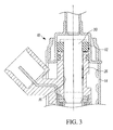
FIG. 3 , Applicant added a secondary seal or O-ring 18 to eliminate water intrusion that may migrate below the primary O-ring 12. However, the secondary seal was found to prevent effective testing of the primary O-ring 12. Failure of the primary O-ring 12 would force AUS32 (urea, indicated by arrows inFIG. 3 ) into theinterior 16 of theinjector 10, leading to premature injector failure. - Accordingly, there exists a need in an injector a secondary seal to prevent ingress of liquid into the injector, while also allowing effective testing of the primary seal.
- An objective of the invention is to fulfill the need referred to above. In accordance with the principles of an embodiment, this objective is obtained by providing a fluid injector that includes a housing and an inlet tube having a portion received in the housing. The inlet tube has an opened end for receiving fluid from an inlet of the injector. A primary seal is disposed about a portion of the inlet tube so as to create a seal between surfaces of the housing, the inlet tube, and the inlet of the injector. A groove is defined in a periphery of the housing and a secondary seal is disposed in the groove and defining a seal between the housing and a portion of the inlet of the injector. A recessed portion is defined in the housing and is in communication with the groove so that due to the recessed portion, an entirety of the secondary seal is not supported by the groove. The recessed portion defines a blow-out volume such that when the primary seal is leak tested by forcing pressurized air through the inlet of the injector, an indication of a leak of the primary seal can be detected when the pressurized air moves past the primary seal and forces a portion of the secondary seal to an unsealed position into the blow-out volume.
- In accordance with another aspect of an embodiment, a method seals a fluid injector. The injector includes a housing and an inlet tube having a portion received in the housing. The inlet tube has an opened end for receiving fluid from an inlet of the injector. The method provides a primary seal disposed about a portion of the inlet tube so as to create a first seal between surfaces of the housing, the inlet tube, and the inlet of the injector. A secondary seal defines a second seal between the housing and a portion of the inlet of the injector. When the primary seal is leak tested by forcing pressurized air through the inlet of the injector causing the pressurized air to move past the primary seal, the method ensures that the second seal can be forced by the pressurized air into an unsealed positon, thereby indicating a leak of the primary seal.
- Other objective, features and characteristics of the present invention, as well as the methods of operation and the functions of the related elements of the structure, the combination of parts and economics of manufacture will become more apparent upon consideration of the following detailed description and appended claims with reference to the accompanying drawings, all of which form a part of this specification.
- The invention will be better understood from the following detailed description of the preferred embodiments thereof, taken in conjunction with the accompanying drawings, wherein like reference numerals refer to like parts, in which:
-
FIG. 1 cross-sectional view of a conventional fluid injector having a primary O-ring to prevent liquid ingress. -
FIG. 2 is an enlarged view of the enclosedportion 2 ofFIG. 1 . -
FIG. 3 is an enlarged sectional view showing a secondary O-ring provided in the injector ofFIG. 1 . -
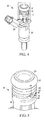
FIG. 4 is perspective view of a fluid injector having a primary seal, a secondary seal and a blow-out volume in accordance with an embodiment, and shown with an inlet cup assembly and shield removed. -
FIG. 5 is an enlarged view of the enclosedportion 5 ofFIG. 4 . -
FIG. 6 is a cross-sectional view of the injector ofFIG. 4 with the secondary seal functioning normally. -
FIG. 7 is an enlarged view of the enclosedportion 7 ofFIG. 6 . -
FIG. 8 is view of the portion of the injector ofFIG. 7 , but shown after the primary seal has failed with the secondary seal being extruded into the blow-out volume during primary seal testing. -
FIG. 9 is a view of the groove in the blow-out volume of the injector ofFIG. 5 , showing an air escape path through the groove and around the secondary seal. - The following description of the preferred embodiment(s) is merely exemplary in nature and is in no way intended to limit the invention, its application, or uses.
- With reference to
FIGs. 4 and6 a fluid injector is shown, generally indicated at 10', in accordance with an embodiment. The injector 10' is constructed and arranged as a Reductant Delivery Unit (RDU) for use in a Selective Catalytic Reduction (SCR) system. As shownFIG. 6 , the injector 10' includes an inlet cup assembly having aninlet cup 20 coupled to acup tube 22 defining an inlet of the injector 10'. Thecup tube 22 is constructed and arranged to be connected to a source of fluid such as urea for introduction into the injector 10'. Theinlet cup 20 is connected to ashield 14, and theshield 24 substantially surrounds ahousing 26, which includes anelectrical connector 28.FIG. 4 does not show the inlet cup assembly or theshield 14 so that components there-under can be seen clearly. - A portion of an
inlet tube 30 is disposed within thehousing 26. Theinlet tube 30 has anopen end 31 for receiving fluid from the inlet cup assembly (injector inlet) that will be ejected from the injector 10'. A primary seal such as an elastomer O-ring 12 is disposed about a periphery of an upper portion of thecylindrical inlet tube 30 adjacent to thehousing 26 to prevent liquid (e.g., water) ingress into theinterior 16 of the injector 10'. Theprimary seal 12 also seals urea from migrating past theinlet cup 20 and between thehousing 26 and theinlet tube 30. Theprimary seal 12 thus provides a seal between theinner surface 32 of theinlet cup 20, an outer surface 34 of theinlet tube 30 and anupper surface 36 of thehousing 26. Asecondary seal 18 such as an elastomer O-ring is disposed in anannular groove 38 formed in a periphery of thehousing 26, generally adjacent to theprimary seal 12. Thesecondary seal 18 defines a seal between thehousing 26 and theinlet cup 20 that prevents water leakage into theinterior 16 that may enter through theshield 14. Also formed as part of thehousing 26 and in communication with thegroove 38 is arecessed portion 40 defining blow-out volume, generally indicated at 42. Therecessed portion 40 extends axially from thegroove 38. Thus, due to therecessed portion 40, thegroove 38 extends less than 360° about the periphery of thehousing 26, leaving a small portion of thesecondary seal 18 unsupported. Therecess portion 40 can be molded into thegroove 38 upon molding thehousing 26. The function of the blow-outvolume 42 will be explained below. - With reference to
FIG. 8 , during the assembly process of the injector 10', theprimary seal 12 is tested to make sure it is functioning properly. To test theprimary seal 12, pressurized air P is forced into the cup tube 22 (the lower end of theinjector 10 is also sealed to allow pressure to build inside the injector 10), such that theprimary seal 12 is exposed to the pressurized air. If theprimary seal 12 is damaged or is functioning improperly, the pressurized air moves past by theprimary seal 12, and thesecondary seal 18 is then exposed to the pressurized air, causing a portion of thesecondary seal 18 to move to an unsealed position by extruding into the blow-outvolume 42 of the recessedportion 40. Thus, since thesecondary seal 18 moves to an unsealed area, a leak due to a faultyprimary seal 12 can be detected. Thesecondary seal 18 must be flexible enough to extrude into the blow-outvolume 42, but be firm enough to remain in position during assembly and during normal use. - In the embodiment, the
recessed portion 38 is generally U-shaped, and has a maximum width W of 3.0 mm. However, it is within the scope of the invention that other shapes and widths may be used. - With reference to
FIG. 5 , asmall groove 44 is in communication with therecessed portion 40 and the blow-outvolume 42. The groove permits thesecondary seal 18 to move less before releasing any pressure during leak testing. Thisgroove 44 is necessary if the injector 10' is inserted deep into theinlet cup 20 since thesecondary seal 18 would not blow-out, giving false leak measurements. The arrows inFIG. 9 show an air path around thesecondary seal 18 using thegroove 44 when thesecondary seal 18 moves to an unsealed position upon testing theprimary seal 12. - Thus, the
secondary seal 18 provides further sealing of the interior 16 of the injector 10' in the event water gets past theprimary seal 12. The blow-outvolume 42, receiving a portion of thesecondary seal 18, allows theprimary seal 12 to be leak tested thereby ensuring the integrity of theprimary seal 12 and preventing urea from entering into the interior 16 of the injector 10'. - The description of the invention is merely exemplary in nature and, thus, variations that do not depart from the gist of the invention are intended to be within the scope of the invention. Such variations are not to be regarded as a departure from the spirit and scope of the invention.
-
- 1. A fluid injector comprising:
- a housing;
- an inlet tube having a portion received in the housing, the inlet tube having an opened end for receiving fluid from an inlet of the injector;
- a primary seal disposed about a portion of the inlet tube so as to create a seal between surfaces of the housing, the inlet tube, and the inlet of the injector;
- a groove defined in a periphery of the housing;
- a secondary seal disposed in the groove and defining a seal between the housing and a portion of the inlet of the injector; and
- a recessed portion defined in the housing and in communication with the groove so that due to the recessed portion, an entirety of the secondary seal is not supported by the groove,
- wherein the recessed portion defines a blow-out volume such that when the primary seal is leak tested by forcing pressurized air through the inlet of the injector, an indication of a leak of the primary seal can be detected when the pressurized air moves past the primary seal and forces a portion of the secondary seal to move to an unsealed position into the blow-out volume.
- 2. The injector of embodiment 1, wherein the recessed portion is substantially U-shaped and extends axially from the groove.
- 3. The injector of
embodiment 2, wherein the recessed portion has a maximum width of about 3.0 mm. - 4. The injector of embodiment 1, wherein the groove is generally annular and the secondary seal is an elastomer O-ring.
- 5. The injector of embodiment 1, wherein the primary seal is an elastomer O-ring.
- 6. The injector of embodiment 1, wherein the secondary seal is generally adjacent to the primary seal.
- 7. The injector of embodiment 1, further comprising:
- an inlet cup assembly coupled to the housing and defining the inlet of the injector.
- 8. The injector of
embodiment 7, further comprising a shield connected to the inlet cup assembly and surrounding a portion of the housing. - 9. The injector of
embodiment 7, wherein the injector is a Reductant Delivery Unit in a Selective Catalytic Reduction system and the primary seal is constructed arranged to seal urea from migrating past the inlet cup assembly and between the housing and the inlet tube and the secondary seal is constructed and arranged to seal liquid from migrating past the inlet cup assembly and between the housing and the inlet tube. - 10. The injector of embodiment 1, further comprising a groove in communication with the recessed portion and constructed and arranged to permit air to move around the secondary seal when the secondary seal moves to the unsealed position during leak testing of the primary seal.
- 11. A method of sealing a fluid injector so that sealing of the injector can be tested, the injector including a housing and an inlet tube having a portion received in the housing, the inlet tube having an opened end for receiving fluid from an inlet of the injector, the method comprising the steps of:
- providing a primary seal disposed about a portion of the inlet tube so as to create a first seal between surfaces of the housing, the inlet tube, and the inlet of the injector;
- providing a secondary seal defining a second seal between the housing and a portion of the inlet of the injector; and
- when the primary seal is leak tested by forcing pressurized air through the inlet of the injector causing the pressurized air to move past the primary seal, ensuring that the second seal can be forced by the pressurized air into an unsealed positon, thereby indicating a leak of the primary seal.
- 12. The method of embodiment 11, wherein the injector further includes an inlet cup assembly coupled to the housing and defining the inlet of the injector, the primary seal defining the first seal between surfaces of the housing, the inlet tube, and surfaces of the inlet cup assembly, and the secondary seal defining the second seal between the housing and a surfaces of the inlet cup assembly.
- 13. The method of
embodiment 12, wherein the injector is a Reductant Delivery Unit in a Selective Catalytic Reduction system and the step of providing the primary seal defines the first seal to seal urea from migrating past the inlet cup assembly and between the housing and the inlet tube and the step of providing the secondary seal defines the second seal to seal liquid from migrating past the inlet cup assembly and between the housing and the inlet tube. - 14. The method of embodiment 13, wherein the injector further includes a shield connected to the inlet cup assembly and surrounding a portion of the housing, with the secondary seal sealing against water that may enter the shield.
- 15. The method of embodiment 11, wherein the step of providing the secondary seal comprises:
- providing a groove in a periphery of the housing, and
- disposing the secondary seal in the groove.
- 16. The method of embodiment 15, wherein the step of providing the groove includes providing an annular groove and the secondary seal is an O-ring disposed in the annular groove.
- 17. The method of embodiment 15, wherein the ensuring step includes:
- providing a recessed portion in the housing and in communication with the groove so that due to the recessed portion, an entirety of the secondary seal is not supported by the groove, so that in the unsealed position of the secondary seal, a portion of the secondary seal enters the recessed portion.
- 18. The method of embodiment 17, wherein the recessed portion is provided as substantially U-shaped and extends axially from the groove.
- 19. The method of embodiment 11, further comprising:
- permitting air to move around the secondary seal when the secondary seal moves to the unsealed position during leak testing of the primary seal.
Claims (15)
- A fluid injector comprising:a housing;an inlet tube having a portion received in the housing, the inlet tube having an opened end for receiving fluid from an inlet of the injector;a primary seal disposed about a portion of the inlet tube so as to create a seal between surfaces of the housing, the inlet tube, and the inlet of the injector;a groove defined in a periphery of the housing;a secondary seal disposed in the groove and defining a seal between the housing and a portion of the inlet of the injector; anda recessed portion defined in the housing and in communication with the groove so that due to the recessed portion, an entirety of the secondary seal is not supported by the groove,wherein the recessed portion defines a blow-out volume such that when the primary seal is leak tested by forcing pressurized air through the inlet of the injector, an indication of a leak of the primary seal can be detected when the pressurized air moves past the primary seal and forces a portion of the secondary seal to move to an unsealed position into the blow-out volume.
- The injector of claim 1, wherein the recessed portion is substantially U-shaped and extends axially from the groove and/or wherein the recessed portion has a maximum width of about 3.0 mm.
- The injector according to any of the preceding claims, wherein the groove is generally annular and the secondary seal is an elastomer O-ring.
- The injector according to any of the preceding claims, wherein the primary seal is an elastomer O-ring and/or wherein the secondary seal is generally adjacent to the primary seal.
- The injector according to any of the preceding claims, further comprising:an inlet cup assembly coupled to the housing and defining the inlet of the injector.
- The injector of claim 5, further comprising a shield connected to the inlet cup assembly and surrounding a portion of the housing and/or wherein the injector is a Reductant Delivery Unit in a Selective Catalytic Reduction system and the primary seal is constructed arranged to seal urea from migrating past the inlet cup assembly and between the housing and the inlet tube and the secondary seal is constructed and arranged to seal liquid from migrating past the inlet cup assembly and between the housing and the inlet tube.
- The injector according to any of the preceding claims, further comprising a groove in communication with the recessed portion and constructed and arranged to permit air to move around the secondary seal when the secondary seal moves to the unsealed position during leak testing of the primary seal.
- A method of sealing a fluid injector so that sealing of the injector can be tested, the injector including a housing and an inlet tube having a portion received in the housing, the inlet tube having an opened end for receiving fluid from an inlet of the injector, the method comprising the steps of:providing a primary seal disposed about a portion of the inlet tube so as to create a first seal between surfaces of the housing, the inlet tube, and the inlet of the injector;providing a secondary seal defining a second seal between the housing and a portion of the inlet of the injector; andwhen the primary seal is leak tested by forcing pressurized air through the inlet of the injector causing the pressurized air to move past the primary seal, ensuring that the second seal can be forced by the pressurized air into an unsealed positon, thereby indicating a leak of the primary seal.
- The method of claim 8, wherein the injector further includes an inlet cup assembly coupled to the housing and defining the inlet of the injector, the primary seal defining the first seal between surfaces of the housing, the inlet tube, and surfaces of the inlet cup assembly, and the secondary seal defining the second seal between the housing and a surfaces of the inlet cup assembly.
- The method of claim 8 or 9, wherein the injector is a Reductant Delivery Unit in a Selective Catalytic Reduction system and the step of providing the primary seal defines the first seal to seal urea from migrating past the inlet cup assembly and between the housing and the inlet tube and the step of providing the secondary seal defines the second seal to seal liquid from migrating past the inlet cup assembly and between the housing and the inlet tube.
- The method of claim 8 to 10, wherein the injector further includes a shield connected to the inlet cup assembly and surrounding a portion of the housing, with the secondary seal sealing against water that may enter the shield.
- The method of claim 8 to 11, wherein the step of providing the secondary seal comprises:providing a groove in a periphery of the housing, anddisposing the secondary seal in the groove.
- The method of claim 12, wherein the step of providing the groove includes providing an annular groove and the secondary seal is an O-ring disposed in the annular groove.
- The method of claim 12 or 13, wherein the ensuring step includes:providing a recessed portion in the housing and in communication with the groove so that due to the recessed portion, an entirety of the secondary seal is not supported by the groove, so that in the unsealed position of the secondary seal, a portion of the secondary seal enters the recessed portion, wherein the recessed portion is in particular provided as substantially U-shaped and extends axially from the groove.
- The method of claim 8 to 14, further comprising:permitting air to move around the secondary seal when the secondary seal moves to the unsealed position during leak testing of the primary seal.
Applications Claiming Priority (2)
| Application Number | Priority Date | Filing Date | Title |
|---|---|---|---|
| US201361901504P | 2013-11-08 | 2013-11-08 | |
| US14/509,216 US9366167B2 (en) | 2013-11-08 | 2014-10-08 | Injector water intrusion seal with blow out volume |
Publications (2)
| Publication Number | Publication Date |
|---|---|
| EP2886846A1 true EP2886846A1 (en) | 2015-06-24 |
| EP2886846B1 EP2886846B1 (en) | 2016-07-06 |
Family
ID=53042884
Family Applications (1)
| Application Number | Title | Priority Date | Filing Date |
|---|---|---|---|
| EP14189320.6A Active EP2886846B1 (en) | 2013-11-08 | 2014-10-17 | Injector water intrusion seal with blow out volume |
Country Status (4)
| Country | Link |
|---|---|
| US (1) | US9366167B2 (en) |
| EP (1) | EP2886846B1 (en) |
| JP (1) | JP5980296B2 (en) |
| CN (1) | CN104963749B (en) |
Citations (5)
| Publication number | Priority date | Publication date | Assignee | Title |
|---|---|---|---|---|
| DE102007030003A1 (en) * | 2007-06-28 | 2009-01-02 | Robert Bosch Gmbh | Fuel injector e.g. common rail injector, testing method for e.g. commercial vehicle, involves registering temporal pressure change of fluid medium at inlet and return line, and inferring tightness and leakage rate of injector from change |
| US20100314470A1 (en) * | 2009-06-11 | 2010-12-16 | Stanadyne Corporation | Injector having swirl structure downstream of valve seat |
| WO2012000038A2 (en) * | 2010-06-30 | 2012-01-05 | Orbital Australia Pty Ltd | Fuel injection assembly |
| WO2012049175A1 (en) * | 2010-10-14 | 2012-04-19 | Emitec Gesellschaft Für Emissionstechnologie Mbh | Mounting for an injector |
| WO2013083522A1 (en) * | 2011-12-08 | 2013-06-13 | Robert Bosch Gmbh | Injection valve, in particular for an internal combustion engine |
Family Cites Families (13)
| Publication number | Priority date | Publication date | Assignee | Title |
|---|---|---|---|---|
| US6047907A (en) * | 1997-12-23 | 2000-04-11 | Siemens Automotive Corporation | Ball valve fuel injector |
| JP3893727B2 (en) * | 1998-03-19 | 2007-03-14 | 株式会社デンソー | Fuel injection valve |
| US6264112B1 (en) * | 1999-05-26 | 2001-07-24 | Delphi Technologies, Inc. | Engine fuel injector |
| JP2001020827A (en) * | 1999-07-09 | 2001-01-23 | Toyota Motor Corp | Fuel injection valve mounting structure |
| DE10116214A1 (en) * | 2001-03-30 | 2002-10-10 | Bosch Gmbh Robert | Device for the aftertreatment of exhaust gases from an internal combustion engine |
| JP2003049748A (en) * | 2001-08-08 | 2003-02-21 | Keihin Corp | Connection structure of fuel injection valve to fuel distribution pipe |
| JP2004353520A (en) * | 2003-05-28 | 2004-12-16 | Mitsubishi Electric Corp | Fuel injection device |
| US7004151B2 (en) * | 2004-06-29 | 2006-02-28 | Millennium Industries Corp. | Vented injector cup |
| DE102007025732B4 (en) | 2007-06-01 | 2012-01-26 | Zinoviy Lerner | Method for tuning of resonant circuits and tunable resonant circuit |
| WO2009054865A1 (en) * | 2007-10-25 | 2009-04-30 | Continental Automotive Systems Us, Inc. | Fluid supply connection for reductant delivery unit for selective catalytic reduction systems |
| DE102009000872B4 (en) | 2009-02-16 | 2018-05-30 | Robert Bosch Gmbh | Injector |
| US8528322B2 (en) | 2011-09-13 | 2013-09-10 | Continental Automotive Systems Us, Inc. | Reductant delivery unit for selective catalytic reduction with freeze accommodation structure |
| JP2013100740A (en) | 2011-11-07 | 2013-05-23 | Keihin Corp | Support structure of fuel injection valve |
-
2014
- 2014-10-08 US US14/509,216 patent/US9366167B2/en active Active
- 2014-10-17 EP EP14189320.6A patent/EP2886846B1/en active Active
- 2014-11-06 JP JP2014226098A patent/JP5980296B2/en active Active
- 2014-11-07 CN CN201410635407.1A patent/CN104963749B/en active Active
Patent Citations (5)
| Publication number | Priority date | Publication date | Assignee | Title |
|---|---|---|---|---|
| DE102007030003A1 (en) * | 2007-06-28 | 2009-01-02 | Robert Bosch Gmbh | Fuel injector e.g. common rail injector, testing method for e.g. commercial vehicle, involves registering temporal pressure change of fluid medium at inlet and return line, and inferring tightness and leakage rate of injector from change |
| US20100314470A1 (en) * | 2009-06-11 | 2010-12-16 | Stanadyne Corporation | Injector having swirl structure downstream of valve seat |
| WO2012000038A2 (en) * | 2010-06-30 | 2012-01-05 | Orbital Australia Pty Ltd | Fuel injection assembly |
| WO2012049175A1 (en) * | 2010-10-14 | 2012-04-19 | Emitec Gesellschaft Für Emissionstechnologie Mbh | Mounting for an injector |
| WO2013083522A1 (en) * | 2011-12-08 | 2013-06-13 | Robert Bosch Gmbh | Injection valve, in particular for an internal combustion engine |
Also Published As
| Publication number | Publication date |
|---|---|
| CN104963749B (en) | 2018-05-15 |
| CN104963749A (en) | 2015-10-07 |
| JP2015094358A (en) | 2015-05-18 |
| EP2886846B1 (en) | 2016-07-06 |
| US9366167B2 (en) | 2016-06-14 |
| JP5980296B2 (en) | 2016-08-31 |
| US20150129679A1 (en) | 2015-05-14 |
Similar Documents
| Publication | Publication Date | Title |
|---|---|---|
| CN110082036B (en) | Pipe body flange weld seam air tightness detection device | |
| RU2015106207A (en) | COOLING SHIRT WITH SEALING | |
| EP3040593A1 (en) | Sealing assembly for hose connector | |
| CN104791560A (en) | Clamping and pressing type anti-leakage compression joint pipe fitting | |
| CN110506199B (en) | Seal inspection device, corresponding tubular joint and use | |
| US20170030466A1 (en) | Seal for pressurized fluid and open interface gap | |
| CN209786066U (en) | Battery sealing nail, cover assembly and battery | |
| EP2886846B1 (en) | Injector water intrusion seal with blow out volume | |
| KR101532741B1 (en) | Connection pipe with watertight and airtight functions | |
| JP2017073204A (en) | Waterproof connector | |
| JP2019503927A (en) | Electrical fluid passage duct for controlling seals in vehicle brakes | |
| KR101412600B1 (en) | Connection pipe with watertight and airtight functions | |
| JP2015137729A (en) | SEALING DEVICE AND METHOD FOR MANUFACTURING SEALING DEVICE | |
| CN105805312A (en) | Pipe orifice sealing air inlet device | |
| US10358912B2 (en) | Test tube with an inlet for filling with fluid and expelling air, and with enhanced resistance and sealing for the BOP testing step in drilling systems | |
| CN217355948U (en) | Sealing connection device for end of externally-wrapped pipeline | |
| ES2251295B1 (en) | MEASUREMENT SENSOR | |
| JP2016180596A (en) | Water tightness testing device, and water tightness testing method using the same | |
| CN103767711A (en) | Sealing cap for connector with electrical connection | |
| US10352633B2 (en) | Flow passage connecting apparatus for heat exchanger | |
| JP5845948B2 (en) | Wire harness, grommet water stop inspection method and grommet water stop inspection device | |
| KR101655938B1 (en) | Device and method for checking sealed state of assembled corrugated pipes | |
| CN113252247B (en) | Test head and be used for gas tightness detecting system of pipeline | |
| CN106687699B (en) | Sealing structure and control cable unit | |
| JP6226379B2 (en) | Press-fitting device |
Legal Events
| Date | Code | Title | Description |
|---|---|---|---|
| PUAI | Public reference made under article 153(3) epc to a published international application that has entered the european phase |
Free format text: ORIGINAL CODE: 0009012 |
|
| 17P | Request for examination filed |
Effective date: 20141017 |
|
| AK | Designated contracting states |
Kind code of ref document: A1 Designated state(s): AL AT BE BG CH CY CZ DE DK EE ES FI FR GB GR HR HU IE IS IT LI LT LU LV MC MK MT NL NO PL PT RO RS SE SI SK SM TR |
|
| AX | Request for extension of the european patent |
Extension state: BA ME |
|
| R17P | Request for examination filed (corrected) |
Effective date: 20151218 |
|
| RBV | Designated contracting states (corrected) |
Designated state(s): AL AT BE BG CH CY CZ DE DK EE ES FI FR GB GR HR HU IE IS IT LI LT LU LV MC MK MT NL NO PL PT RO RS SE SI SK SM TR |
|
| GRAP | Despatch of communication of intention to grant a patent |
Free format text: ORIGINAL CODE: EPIDOSNIGR1 |
|
| RIC1 | Information provided on ipc code assigned before grant |
Ipc: F02M 55/00 20060101ALI20160127BHEP Ipc: F01N 3/20 20060101ALI20160127BHEP Ipc: F02M 61/16 20060101ALI20160127BHEP Ipc: F02M 65/00 20060101AFI20160127BHEP |
|
| INTG | Intention to grant announced |
Effective date: 20160217 |
|
| RAP1 | Party data changed (applicant data changed or rights of an application transferred) |
Owner name: CONTINENTAL AUTOMOTIVE SYSTEMS, INC. |
|
| GRAS | Grant fee paid |
Free format text: ORIGINAL CODE: EPIDOSNIGR3 |
|
| GRAA | (expected) grant |
Free format text: ORIGINAL CODE: 0009210 |
|
| AK | Designated contracting states |
Kind code of ref document: B1 Designated state(s): AL AT BE BG CH CY CZ DE DK EE ES FI FR GB GR HR HU IE IS IT LI LT LU LV MC MK MT NL NO PL PT RO RS SE SI SK SM TR |
|
| REG | Reference to a national code |
Ref country code: GB Ref legal event code: FG4D |
|
| REG | Reference to a national code |
Ref country code: AT Ref legal event code: REF Ref document number: 810915 Country of ref document: AT Kind code of ref document: T Effective date: 20160715 Ref country code: CH Ref legal event code: EP |
|
| REG | Reference to a national code |
Ref country code: IE Ref legal event code: FG4D |
|
| REG | Reference to a national code |
Ref country code: DE Ref legal event code: R096 Ref document number: 602014002573 Country of ref document: DE |
|
| REG | Reference to a national code |
Ref country code: FR Ref legal event code: PLFP Year of fee payment: 3 |
|
| REG | Reference to a national code |
Ref country code: NL Ref legal event code: MP Effective date: 20160706 |
|
| REG | Reference to a national code |
Ref country code: LT Ref legal event code: MG4D |
|
| REG | Reference to a national code |
Ref country code: AT Ref legal event code: MK05 Ref document number: 810915 Country of ref document: AT Kind code of ref document: T Effective date: 20160706 |
|
| PG25 | Lapsed in a contracting state [announced via postgrant information from national office to epo] |
Ref country code: IS Free format text: LAPSE BECAUSE OF FAILURE TO SUBMIT A TRANSLATION OF THE DESCRIPTION OR TO PAY THE FEE WITHIN THE PRESCRIBED TIME-LIMIT Effective date: 20161106 Ref country code: NO Free format text: LAPSE BECAUSE OF FAILURE TO SUBMIT A TRANSLATION OF THE DESCRIPTION OR TO PAY THE FEE WITHIN THE PRESCRIBED TIME-LIMIT Effective date: 20161006 Ref country code: HR Free format text: LAPSE BECAUSE OF FAILURE TO SUBMIT A TRANSLATION OF THE DESCRIPTION OR TO PAY THE FEE WITHIN THE PRESCRIBED TIME-LIMIT Effective date: 20160706 Ref country code: NL Free format text: LAPSE BECAUSE OF FAILURE TO SUBMIT A TRANSLATION OF THE DESCRIPTION OR TO PAY THE FEE WITHIN THE PRESCRIBED TIME-LIMIT Effective date: 20160706 Ref country code: FI Free format text: LAPSE BECAUSE OF FAILURE TO SUBMIT A TRANSLATION OF THE DESCRIPTION OR TO PAY THE FEE WITHIN THE PRESCRIBED TIME-LIMIT Effective date: 20160706 Ref country code: LT Free format text: LAPSE BECAUSE OF FAILURE TO SUBMIT A TRANSLATION OF THE DESCRIPTION OR TO PAY THE FEE WITHIN THE PRESCRIBED TIME-LIMIT Effective date: 20160706 Ref country code: RS Free format text: LAPSE BECAUSE OF FAILURE TO SUBMIT A TRANSLATION OF THE DESCRIPTION OR TO PAY THE FEE WITHIN THE PRESCRIBED TIME-LIMIT Effective date: 20160706 |
|
| PG25 | Lapsed in a contracting state [announced via postgrant information from national office to epo] |
Ref country code: LV Free format text: LAPSE BECAUSE OF FAILURE TO SUBMIT A TRANSLATION OF THE DESCRIPTION OR TO PAY THE FEE WITHIN THE PRESCRIBED TIME-LIMIT Effective date: 20160706 Ref country code: ES Free format text: LAPSE BECAUSE OF FAILURE TO SUBMIT A TRANSLATION OF THE DESCRIPTION OR TO PAY THE FEE WITHIN THE PRESCRIBED TIME-LIMIT Effective date: 20160706 Ref country code: PT Free format text: LAPSE BECAUSE OF FAILURE TO SUBMIT A TRANSLATION OF THE DESCRIPTION OR TO PAY THE FEE WITHIN THE PRESCRIBED TIME-LIMIT Effective date: 20161107 Ref country code: GR Free format text: LAPSE BECAUSE OF FAILURE TO SUBMIT A TRANSLATION OF THE DESCRIPTION OR TO PAY THE FEE WITHIN THE PRESCRIBED TIME-LIMIT Effective date: 20161007 Ref country code: AT Free format text: LAPSE BECAUSE OF FAILURE TO SUBMIT A TRANSLATION OF THE DESCRIPTION OR TO PAY THE FEE WITHIN THE PRESCRIBED TIME-LIMIT Effective date: 20160706 Ref country code: BE Free format text: LAPSE BECAUSE OF NON-PAYMENT OF DUE FEES Effective date: 20160706 Ref country code: SE Free format text: LAPSE BECAUSE OF FAILURE TO SUBMIT A TRANSLATION OF THE DESCRIPTION OR TO PAY THE FEE WITHIN THE PRESCRIBED TIME-LIMIT Effective date: 20160706 Ref country code: PL Free format text: LAPSE BECAUSE OF FAILURE TO SUBMIT A TRANSLATION OF THE DESCRIPTION OR TO PAY THE FEE WITHIN THE PRESCRIBED TIME-LIMIT Effective date: 20160706 |
|
| REG | Reference to a national code |
Ref country code: DE Ref legal event code: R097 Ref document number: 602014002573 Country of ref document: DE |
|
| PG25 | Lapsed in a contracting state [announced via postgrant information from national office to epo] |
Ref country code: EE Free format text: LAPSE BECAUSE OF FAILURE TO SUBMIT A TRANSLATION OF THE DESCRIPTION OR TO PAY THE FEE WITHIN THE PRESCRIBED TIME-LIMIT Effective date: 20160706 Ref country code: RO Free format text: LAPSE BECAUSE OF FAILURE TO SUBMIT A TRANSLATION OF THE DESCRIPTION OR TO PAY THE FEE WITHIN THE PRESCRIBED TIME-LIMIT Effective date: 20160706 |
|
| PLBE | No opposition filed within time limit |
Free format text: ORIGINAL CODE: 0009261 |
|
| STAA | Information on the status of an ep patent application or granted ep patent |
Free format text: STATUS: NO OPPOSITION FILED WITHIN TIME LIMIT |
|
| PG25 | Lapsed in a contracting state [announced via postgrant information from national office to epo] |
Ref country code: CZ Free format text: LAPSE BECAUSE OF FAILURE TO SUBMIT A TRANSLATION OF THE DESCRIPTION OR TO PAY THE FEE WITHIN THE PRESCRIBED TIME-LIMIT Effective date: 20160706 Ref country code: SK Free format text: LAPSE BECAUSE OF FAILURE TO SUBMIT A TRANSLATION OF THE DESCRIPTION OR TO PAY THE FEE WITHIN THE PRESCRIBED TIME-LIMIT Effective date: 20160706 Ref country code: DK Free format text: LAPSE BECAUSE OF FAILURE TO SUBMIT A TRANSLATION OF THE DESCRIPTION OR TO PAY THE FEE WITHIN THE PRESCRIBED TIME-LIMIT Effective date: 20160706 Ref country code: BG Free format text: LAPSE BECAUSE OF FAILURE TO SUBMIT A TRANSLATION OF THE DESCRIPTION OR TO PAY THE FEE WITHIN THE PRESCRIBED TIME-LIMIT Effective date: 20161006 Ref country code: SM Free format text: LAPSE BECAUSE OF FAILURE TO SUBMIT A TRANSLATION OF THE DESCRIPTION OR TO PAY THE FEE WITHIN THE PRESCRIBED TIME-LIMIT Effective date: 20160706 |
|
| 26N | No opposition filed |
Effective date: 20170407 |
|
| REG | Reference to a national code |
Ref country code: IE Ref legal event code: MM4A |
|
| PG25 | Lapsed in a contracting state [announced via postgrant information from national office to epo] |
Ref country code: SI Free format text: LAPSE BECAUSE OF FAILURE TO SUBMIT A TRANSLATION OF THE DESCRIPTION OR TO PAY THE FEE WITHIN THE PRESCRIBED TIME-LIMIT Effective date: 20160706 Ref country code: LU Free format text: LAPSE BECAUSE OF NON-PAYMENT OF DUE FEES Effective date: 20161017 |
|
| REG | Reference to a national code |
Ref country code: FR Ref legal event code: PLFP Year of fee payment: 4 |
|
| PG25 | Lapsed in a contracting state [announced via postgrant information from national office to epo] |
Ref country code: IE Free format text: LAPSE BECAUSE OF NON-PAYMENT OF DUE FEES Effective date: 20161017 |
|
| PG25 | Lapsed in a contracting state [announced via postgrant information from national office to epo] |
Ref country code: HU Free format text: LAPSE BECAUSE OF FAILURE TO SUBMIT A TRANSLATION OF THE DESCRIPTION OR TO PAY THE FEE WITHIN THE PRESCRIBED TIME-LIMIT; INVALID AB INITIO Effective date: 20141017 |
|
| REG | Reference to a national code |
Ref country code: CH Ref legal event code: PL |
|
| PG25 | Lapsed in a contracting state [announced via postgrant information from national office to epo] |
Ref country code: MC Free format text: LAPSE BECAUSE OF FAILURE TO SUBMIT A TRANSLATION OF THE DESCRIPTION OR TO PAY THE FEE WITHIN THE PRESCRIBED TIME-LIMIT Effective date: 20160706 Ref country code: CY Free format text: LAPSE BECAUSE OF FAILURE TO SUBMIT A TRANSLATION OF THE DESCRIPTION OR TO PAY THE FEE WITHIN THE PRESCRIBED TIME-LIMIT Effective date: 20160706 Ref country code: MK Free format text: LAPSE BECAUSE OF FAILURE TO SUBMIT A TRANSLATION OF THE DESCRIPTION OR TO PAY THE FEE WITHIN THE PRESCRIBED TIME-LIMIT Effective date: 20160706 Ref country code: MT Free format text: LAPSE BECAUSE OF NON-PAYMENT OF DUE FEES Effective date: 20161031 |
|
| PG25 | Lapsed in a contracting state [announced via postgrant information from national office to epo] |
Ref country code: LI Free format text: LAPSE BECAUSE OF NON-PAYMENT OF DUE FEES Effective date: 20171031 Ref country code: CH Free format text: LAPSE BECAUSE OF NON-PAYMENT OF DUE FEES Effective date: 20171031 |
|
| REG | Reference to a national code |
Ref country code: FR Ref legal event code: PLFP Year of fee payment: 5 |
|
| PG25 | Lapsed in a contracting state [announced via postgrant information from national office to epo] |
Ref country code: TR Free format text: LAPSE BECAUSE OF FAILURE TO SUBMIT A TRANSLATION OF THE DESCRIPTION OR TO PAY THE FEE WITHIN THE PRESCRIBED TIME-LIMIT Effective date: 20160706 Ref country code: AL Free format text: LAPSE BECAUSE OF FAILURE TO SUBMIT A TRANSLATION OF THE DESCRIPTION OR TO PAY THE FEE WITHIN THE PRESCRIBED TIME-LIMIT Effective date: 20160706 |
|
| GBPC | Gb: european patent ceased through non-payment of renewal fee |
Effective date: 20181017 |
|
| PG25 | Lapsed in a contracting state [announced via postgrant information from national office to epo] |
Ref country code: GB Free format text: LAPSE BECAUSE OF NON-PAYMENT OF DUE FEES Effective date: 20181017 |
|
| REG | Reference to a national code |
Ref country code: DE Ref legal event code: R081 Ref document number: 602014002573 Country of ref document: DE Owner name: VITESCO TECHNOLOGIES USA, LLC, AUBURN HILLS, US Free format text: FORMER OWNER: CONTINENTAL AUTOMOTIVE SYSTEMS, INC., AUBURN HILLS, MICH., US Ref country code: DE Ref legal event code: R081 Ref document number: 602014002573 Country of ref document: DE Owner name: SCHAEFFLER TECHNOLOGIES AG & CO. KG, DE Free format text: FORMER OWNER: CONTINENTAL AUTOMOTIVE SYSTEMS, INC., AUBURN HILLS, MICH., US |
|
| P01 | Opt-out of the competence of the unified patent court (upc) registered |
Effective date: 20230530 |
|
| REG | Reference to a national code |
Ref country code: DE Ref legal event code: R081 Ref document number: 602014002573 Country of ref document: DE Owner name: SCHAEFFLER TECHNOLOGIES AG & CO. KG, DE Free format text: FORMER OWNER: VITESCO TECHNOLOGIES USA, LLC, AUBURN HILLS, MI, US Ref country code: DE Ref legal event code: R082 Ref document number: 602014002573 Country of ref document: DE |
|
| PGFP | Annual fee paid to national office [announced via postgrant information from national office to epo] |
Ref country code: DE Payment date: 20251031 Year of fee payment: 12 |
|
| PGFP | Annual fee paid to national office [announced via postgrant information from national office to epo] |
Ref country code: IT Payment date: 20251024 Year of fee payment: 12 |
|
| PGFP | Annual fee paid to national office [announced via postgrant information from national office to epo] |
Ref country code: FR Payment date: 20251030 Year of fee payment: 12 |