EP2886489B1 - Packaging system for insulation materials - Google Patents
Packaging system for insulation materials Download PDFInfo
- Publication number
- EP2886489B1 EP2886489B1 EP13198937.8A EP13198937A EP2886489B1 EP 2886489 B1 EP2886489 B1 EP 2886489B1 EP 13198937 A EP13198937 A EP 13198937A EP 2886489 B1 EP2886489 B1 EP 2886489B1
- Authority
- EP
- European Patent Office
- Prior art keywords
- packaging system
- top plate
- mantle
- packaging
- bottom plate
- Prior art date
- Legal status (The legal status is an assumption and is not a legal conclusion. Google has not performed a legal analysis and makes no representation as to the accuracy of the status listed.)
- Active
Links
Images





Classifications
-
- B—PERFORMING OPERATIONS; TRANSPORTING
- B65—CONVEYING; PACKING; STORING; HANDLING THIN OR FILAMENTARY MATERIAL
- B65D—CONTAINERS FOR STORAGE OR TRANSPORT OF ARTICLES OR MATERIALS, e.g. BAGS, BARRELS, BOTTLES, BOXES, CANS, CARTONS, CRATES, DRUMS, JARS, TANKS, HOPPERS, FORWARDING CONTAINERS; ACCESSORIES, CLOSURES, OR FITTINGS THEREFOR; PACKAGING ELEMENTS; PACKAGES
- B65D21/00—Nestable, stackable or joinable containers; Containers of variable capacity
- B65D21/02—Containers specially shaped, or provided with fittings or attachments, to facilitate nesting, stacking, or joining together
- B65D21/0209—Containers specially shaped, or provided with fittings or attachments, to facilitate nesting, stacking, or joining together stackable or joined together one-upon-the-other in the upright or upside-down position
- B65D21/0217—Containers with a closure presenting stacking elements
- B65D21/022—Containers with a closure presenting stacking elements the bottom presenting projecting peripheral elements receiving or surrounding the closure or peripheral elements projecting therefrom
-
- B—PERFORMING OPERATIONS; TRANSPORTING
- B65—CONVEYING; PACKING; STORING; HANDLING THIN OR FILAMENTARY MATERIAL
- B65D—CONTAINERS FOR STORAGE OR TRANSPORT OF ARTICLES OR MATERIALS, e.g. BAGS, BARRELS, BOTTLES, BOXES, CANS, CARTONS, CRATES, DRUMS, JARS, TANKS, HOPPERS, FORWARDING CONTAINERS; ACCESSORIES, CLOSURES, OR FITTINGS THEREFOR; PACKAGING ELEMENTS; PACKAGES
- B65D85/00—Containers, packaging elements or packages, specially adapted for particular articles or materials
- B65D85/07—Containers, packaging elements or packages, specially adapted for particular articles or materials for compressible or flexible articles
- B65D85/08—Containers, packaging elements or packages, specially adapted for particular articles or materials for compressible or flexible articles rod-shaped or tubular
- B65D85/10—Containers, packaging elements or packages, specially adapted for particular articles or materials for compressible or flexible articles rod-shaped or tubular for cigarettes
- B65D85/1018—Container formed by a flexible material, i.e. soft-packages
-
- B—PERFORMING OPERATIONS; TRANSPORTING
- B65—CONVEYING; PACKING; STORING; HANDLING THIN OR FILAMENTARY MATERIAL
- B65D—CONTAINERS FOR STORAGE OR TRANSPORT OF ARTICLES OR MATERIALS, e.g. BAGS, BARRELS, BOTTLES, BOXES, CANS, CARTONS, CRATES, DRUMS, JARS, TANKS, HOPPERS, FORWARDING CONTAINERS; ACCESSORIES, CLOSURES, OR FITTINGS THEREFOR; PACKAGING ELEMENTS; PACKAGES
- B65D81/00—Containers, packaging elements, or packages, for contents presenting particular transport or storage problems, or adapted to be used for non-packaging purposes after removal of contents
- B65D81/02—Containers, packaging elements, or packages, for contents presenting particular transport or storage problems, or adapted to be used for non-packaging purposes after removal of contents specially adapted to protect contents from mechanical damage
-
- B—PERFORMING OPERATIONS; TRANSPORTING
- B21—MECHANICAL METAL-WORKING WITHOUT ESSENTIALLY REMOVING MATERIAL; PUNCHING METAL
- B21C—MANUFACTURE OF METAL SHEETS, WIRE, RODS, TUBES, PROFILES OR LIKE SEMI-MANUFACTURED PRODUCTS OTHERWISE THAN BY ROLLING; AUXILIARY OPERATIONS USED IN CONNECTION WITH METAL-WORKING WITHOUT ESSENTIALLY REMOVING MATERIAL
- B21C23/00—Extruding metal; Impact extrusion
-
- B—PERFORMING OPERATIONS; TRANSPORTING
- B21—MECHANICAL METAL-WORKING WITHOUT ESSENTIALLY REMOVING MATERIAL; PUNCHING METAL
- B21D—WORKING OR PROCESSING OF SHEET METAL OR METAL TUBES, RODS OR PROFILES WITHOUT ESSENTIALLY REMOVING MATERIAL; PUNCHING METAL
- B21D22/00—Shaping without cutting, by stamping, spinning, or deep-drawing
- B21D22/20—Deep-drawing
-
- B—PERFORMING OPERATIONS; TRANSPORTING
- B65—CONVEYING; PACKING; STORING; HANDLING THIN OR FILAMENTARY MATERIAL
- B65B—MACHINES, APPARATUS OR DEVICES FOR, OR METHODS OF, PACKAGING ARTICLES OR MATERIALS; UNPACKING
- B65B11/00—Wrapping, e.g. partially or wholly enclosing, articles or quantities of material, in strips, sheets or blanks, of flexible material
-
- B—PERFORMING OPERATIONS; TRANSPORTING
- B65—CONVEYING; PACKING; STORING; HANDLING THIN OR FILAMENTARY MATERIAL
- B65B—MACHINES, APPARATUS OR DEVICES FOR, OR METHODS OF, PACKAGING ARTICLES OR MATERIALS; UNPACKING
- B65B55/00—Preserving, protecting or purifying packages or package contents in association with packaging
-
- B—PERFORMING OPERATIONS; TRANSPORTING
- B65—CONVEYING; PACKING; STORING; HANDLING THIN OR FILAMENTARY MATERIAL
- B65B—MACHINES, APPARATUS OR DEVICES FOR, OR METHODS OF, PACKAGING ARTICLES OR MATERIALS; UNPACKING
- B65B7/00—Closing containers or receptacles after filling
- B65B7/16—Closing semi-rigid or rigid containers or receptacles not deformed by, or not taking-up shape of, contents, e.g. boxes or cartons
- B65B7/28—Closing semi-rigid or rigid containers or receptacles not deformed by, or not taking-up shape of, contents, e.g. boxes or cartons by applying separate preformed closures, e.g. lids, covers
-
- B—PERFORMING OPERATIONS; TRANSPORTING
- B65—CONVEYING; PACKING; STORING; HANDLING THIN OR FILAMENTARY MATERIAL
- B65D—CONTAINERS FOR STORAGE OR TRANSPORT OF ARTICLES OR MATERIALS, e.g. BAGS, BARRELS, BOTTLES, BOXES, CANS, CARTONS, CRATES, DRUMS, JARS, TANKS, HOPPERS, FORWARDING CONTAINERS; ACCESSORIES, CLOSURES, OR FITTINGS THEREFOR; PACKAGING ELEMENTS; PACKAGES
- B65D15/00—Containers having bodies formed by interconnecting or uniting two or more rigid, or substantially rigid, sections made of different materials
- B65D15/24—Connections between walls
-
- B—PERFORMING OPERATIONS; TRANSPORTING
- B65—CONVEYING; PACKING; STORING; HANDLING THIN OR FILAMENTARY MATERIAL
- B65D—CONTAINERS FOR STORAGE OR TRANSPORT OF ARTICLES OR MATERIALS, e.g. BAGS, BARRELS, BOTTLES, BOXES, CANS, CARTONS, CRATES, DRUMS, JARS, TANKS, HOPPERS, FORWARDING CONTAINERS; ACCESSORIES, CLOSURES, OR FITTINGS THEREFOR; PACKAGING ELEMENTS; PACKAGES
- B65D21/00—Nestable, stackable or joinable containers; Containers of variable capacity
- B65D21/02—Containers specially shaped, or provided with fittings or attachments, to facilitate nesting, stacking, or joining together
- B65D21/0209—Containers specially shaped, or provided with fittings or attachments, to facilitate nesting, stacking, or joining together stackable or joined together one-upon-the-other in the upright or upside-down position
- B65D21/023—Closed containers provided with local cooperating elements in the top and bottom surfaces, e.g. projection and recess
-
- B—PERFORMING OPERATIONS; TRANSPORTING
- B65—CONVEYING; PACKING; STORING; HANDLING THIN OR FILAMENTARY MATERIAL
- B65D—CONTAINERS FOR STORAGE OR TRANSPORT OF ARTICLES OR MATERIALS, e.g. BAGS, BARRELS, BOTTLES, BOXES, CANS, CARTONS, CRATES, DRUMS, JARS, TANKS, HOPPERS, FORWARDING CONTAINERS; ACCESSORIES, CLOSURES, OR FITTINGS THEREFOR; PACKAGING ELEMENTS; PACKAGES
- B65D25/00—Details of other kinds or types of rigid or semi-rigid containers
- B65D25/28—Handles
-
- B—PERFORMING OPERATIONS; TRANSPORTING
- B65—CONVEYING; PACKING; STORING; HANDLING THIN OR FILAMENTARY MATERIAL
- B65D—CONTAINERS FOR STORAGE OR TRANSPORT OF ARTICLES OR MATERIALS, e.g. BAGS, BARRELS, BOTTLES, BOXES, CANS, CARTONS, CRATES, DRUMS, JARS, TANKS, HOPPERS, FORWARDING CONTAINERS; ACCESSORIES, CLOSURES, OR FITTINGS THEREFOR; PACKAGING ELEMENTS; PACKAGES
- B65D51/00—Closures not otherwise provided for
- B65D51/16—Closures not otherwise provided for with means for venting air or gas
- B65D51/1605—Closures not otherwise provided for with means for venting air or gas whereby the interior of the container is maintained in permanent gaseous communication with the exterior
- B65D51/1611—Closures not otherwise provided for with means for venting air or gas whereby the interior of the container is maintained in permanent gaseous communication with the exterior by means of an orifice, capillary or labyrinth passage
-
- B—PERFORMING OPERATIONS; TRANSPORTING
- B65—CONVEYING; PACKING; STORING; HANDLING THIN OR FILAMENTARY MATERIAL
- B65D—CONTAINERS FOR STORAGE OR TRANSPORT OF ARTICLES OR MATERIALS, e.g. BAGS, BARRELS, BOTTLES, BOXES, CANS, CARTONS, CRATES, DRUMS, JARS, TANKS, HOPPERS, FORWARDING CONTAINERS; ACCESSORIES, CLOSURES, OR FITTINGS THEREFOR; PACKAGING ELEMENTS; PACKAGES
- B65D85/00—Containers, packaging elements or packages, specially adapted for particular articles or materials
- B65D85/07—Containers, packaging elements or packages, specially adapted for particular articles or materials for compressible or flexible articles
-
- B—PERFORMING OPERATIONS; TRANSPORTING
- B65—CONVEYING; PACKING; STORING; HANDLING THIN OR FILAMENTARY MATERIAL
- B65D—CONTAINERS FOR STORAGE OR TRANSPORT OF ARTICLES OR MATERIALS, e.g. BAGS, BARRELS, BOTTLES, BOXES, CANS, CARTONS, CRATES, DRUMS, JARS, TANKS, HOPPERS, FORWARDING CONTAINERS; ACCESSORIES, CLOSURES, OR FITTINGS THEREFOR; PACKAGING ELEMENTS; PACKAGES
- B65D85/00—Containers, packaging elements or packages, specially adapted for particular articles or materials
- B65D85/70—Containers, packaging elements or packages, specially adapted for particular articles or materials for materials not otherwise provided for
Definitions
- the present invention relates to a packaging system to enclose, protect, store and transport insulation materials, with the possibility to pack with no to low or high compression, preferably to provide ventilation when packaged and to enable indoors or outdoors storage, exhibiting easy and economic as well as urban application, storage and transport as well as easy opening, the manufacture of such packaging and the use of such packaging.
- Insulation materials no matter if fibre or polymer foam based, show porous structures being sensitive to humidity or water intake (which would increase the thermal conductivity and thus decrease or even destroy the insulation effect). Additionally, as entrapped air or cell gas is the best insulator and not the surrounding fibre or foam, low densities are always targeted, however, leading to huge volume per weight unit in storage and transport. Some attempts have been made to improve the packaging of voluminous, rather soft insulation materials, such as in US 3,587,201 A , where tubular shaped insulation is compressed by means of two box parts, similarly to DE 298 25 177 U1 .
- WO 2006/102893 A1 discloses the wrapping of laminar (mat shape) insulation by foils or films, similar to DE 602 04 392 T2 / EP 1 283 181 A1 , where the packaging foil can also be used as a vapour barrier when mounting later on.
- GB 1 418 882 A a wrapped insulation is reduced in volume by applying vacuum.
- EP 0 275 473 A1 also claims the use of vacuum using a construction where a bundle of insulation material is wrapped with a top and bottom "plate” being mounted and vacuum being applied through the perforated bottom plate, and then the whole construction is wrapped for airtight sealing.
- US 3,889,444 A eventually, will use vacuum on a rolled insulation mat packaged into an envelope with sausage like shape.
- EP 0 592 314 A1 describes a process where insulation blankets in tubular form are put together in a way that a second layer of blankets is put on top of a first layer, then the whole construction is wrapped with foil and in parallel the pallet for transport is integrated.
- EP 0 704 384 A2 is claiming a group of six insulation material rolls, each of them wrapped in packaging to be compressed and fixed, which is put around a seventh central roll eventually forming a roughly hexagonal outer shape which is then again being wrapped.
- EP 2 646 340 A2 finally claims an insulation material being rolled an equipped with a rather stable wrapping comprising a handle film; however, there is no moisture or weathering protection.
- GB 2 300 622 A discloses features falling under the preamble of claim 1. US 123 826 A is further prior art.
- a major object of the present invention thus is to provide a packaging system not showing the above mentioned deficiencies but exhibiting stability for stacking the packed goods, and also to protect them mechanically from compression or damage, weatherability to allow transport and storage, as an optional feature ventilation to remove smell from the insulation goods but also to prevent anaerobic processes (e.g. of reversion, degradation), easy packaging and opening, and economic and ecological production, i.e. low manufacturing complexity and costs as well as space-saving, energy-saving and ecological sustainability and optionally reusability and/or recyclability.
- the present invention provides a packaging system comprising the features of independent claim 1. Besides the positive effects mentioned before, the rims in the top and bottom plate guide, fix and stabilize the mantle horizontally and vertically so that a highly stable packing system is established, wherein - in a preferred embodiment - the mantle is additionally pressed against the insulation material to be accommodated within the packing system.
- the declination on the top plate provides water drain properties.
- the top plate and the bottom plate comprise at least one opening to provide forced ventilation of the inside of the packaging.
- the openings in the top plate and in the bottom plate are arranged neighboured in a way that the openings are not blocked and ventilation is ensured when packing systems are stacked.
- the mantle and top and bottom plates are connected by adhesives, mechanical connection or welding to form a closed packaging.
- This packaging can be easily opened due to the fact that the connections are sufficiently easy to unleash / break and/or do not reach over the entire distance to be connected.
- the outer contour is in one embodiment cylindrical or of cone or of reverse cone shape. Thereby, a solid device for accommodating insulation material is provided.
- the material for the mantle and top and bottom plates is in particular chosen from massive and/or expanded recyclable materials, preferably from massive and/or expanded thermoplasts, especially preferred from expanded and/or massive polyolefins and/or thermoplastic biopolymers and/or polyalkylidene terephthalates.
- At least the top plate has a declination by dome shape, as well as distance keepers on top.
- the dome shape is suitable for water drain and stability purpose.
- the distance keepers ensure a gap between two packaging systems.
- an insert is arranged at least on the side of the top plate facing the interior of the packaging system.
- a closed space may be created for accommodating additional items.
- printed media is arranged in a closed space created by the use of the insert.
- the printed media is, thereby, disposed with the packaging system containing e.g. the insulation material, and cannot get lost.
- an adhesive product for insulation materials is arranged in a closed space created by the insert.
- the adhesive product can be used e.g. for seam sealing when removing e.g. the insulation material accommodated in the packaging system.
- a handle and/or handle bar is provided at the packaging system which facilitates handling of the packing.
- the mantle has a minimum thickness of 100 micron and the top plate and/or bottom plate has a thickness of at least 150 micron at their thinnest point.
- the maximum thickness of the mantle is 5 mm and the maximum thickness of top and/or bottom plates is 10 mm.
- the individual parts of the packaging system according to the present invention are made by extrusion, foil blowing, deep-drawing, casting or moulding, preferably by extrusion of the mantle and moulding of the top and bottom plates.
- the packaging system can be obtained in a cost-effective manner.
- the present invention further refers to a method according to claim 13 and a use according to claim 14, which may be combined with preferred features outlined above.
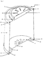
- a packaging system 1 comprises a foil/wrapping (mantle) 2 connecting a top plate 3 and a bottom plate 4.
- the packaging system 1 as a whole can be of any outer shape, such a circular/round/oval, rectangular/square, pentagonal/hexagonal/polygonal etc., whereas round or rectangular shape is preferred, and round shape is especially preferred, leading to a cylindrical form of the foil2.
- the material for the packaging system 1 comprises at least one layer of metal or fibre (paper, carton, tissue) based material or polymer (thermoplast, TPE, thermoset) based material, or any combinations thereof.
- paper or thermoplast based materials especially preferred are thermoplasts, such as polyolefins (PE, PP etc.), styrenics (PS, ABS, SAN, SEBS etc.), polyesters (polyurethanes, polycarbonate, polyalkylidene terephthalates like PET, etc.), polyethers (POM, PEEK etc.), polyamides, polyimides, halogenated polymers (PVC, CPE, CSM etc.), biopolymers (polylactides PLA, cellulose based polymers, thermoplastic starch TPS, polyhydroxyalkanoates, such as PHB, etc.), PMMA, or any combinations thereof.
- the materials can be massive or expanded to foam or sponge, or any combinations thereof.
- Polymer based materials may contain UV and/or IR
- the foil 2 comprises at least one layer of any of the a.m. materials, preferably polymer or paper based material, especially preferred thermoplast based material. For good weathering and outdoor resistance waterproof coated corrugated paper or UV stable / stabilized thermoplasts are preferred.
- the foil 2 can be fixed in the packaging system 1 in a way that it is fully cylindrical, but preferably in a way that it is cone or reverse cone like, see fig. 2a and b. Both embodiments are advantageous for the applications, on the one hand due to improved ventilation -as there is always a gap between the foil 2 and the insulation material 6 to be packaged-, on the other hand due to the fact that the insulation material 6 is not fully compressed, but can be fixed and transported either by holding it on its top (cone shape, fig. 2b ) or by holding it on its bottom (reverse cone, fig. 2a ), the latter embodiment even allowing to transport the insulation material 6 literally levitating, as it is not necessarily touching the bottom plate 3 or its variations (see fig. 2a ).
- the foil 2 can comprise openings for ventilation (preferably on its top when being used in the reverse cone configuration), reinforcing structures, such as ribs, corrugated structures etc. It can be labelled or printed or showing embossed structures.
- the foil 2 can be monolithic / seamless or can comprise a seam and/or an overlap. It can comprise structures 47 for closing and/or opening it, see fig. 8 , such as hinges, hooks, buttons, latches, or the like, or any combinations thereof. These structures 47 for opening / closing can be used to connect the foil 2 at its overlap and/or to connect the foil 2 to the top plate 3 and/or the bottom plate 4.
- the foil 2 can comprise battlement like recesses on its top and/or bottom edge to fit into respective slots in accordingly designed top and/or base plates.
- the protrusions resulting from the grooves 31 of the top plate 3 then would not run over the full perimeter of the top plate 3 but would be interrupted, as the battlement lap configuration of the foil 2 would require less slot space than a continuous edge.
- water e.g. from rain could run off the top plate 3 even more easily as with the "virtual declination" 39, see fig. 5b , which is described further below.
- the top plate 3 and the bottom plate 4 -and their variations 3/4,3/4a,3/4b- comprise at least one layer of any of the a.m. materials each, preferably polymer or paper based material, especially preferred thermoplast based material. For good weathering and outdoor resistance waterproof coated corrugated paper or UV stable / stabilized thermoplasts are preferred.
- the top plate 3 and the bottom plate 4 are designed in a way to fit one into each other to enable the packaging system 1 to be stacked infinitely in a slot and key or tongue and groove manner.
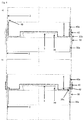
- the plates 3 and 4 comprise grooves and protrusions 31,41,42, see fig. 1 and 5 ; 33,43 see fig.2 , where a groove on one side of the plate may result in a protrusion on the other side of the plate) which fit into each other.
- the top and bottom plates can be of significantly different shape, such as in fig. 1 and 7 , or of identical shape, such as in fig. 2 for 3/4, 3/4a,3/4b.
- both top and bottom plate 3,4,3/4,3/4a,3/4b can comprise rims -30, 30a, 30b, 40, 40a as in fig. 1 and 5 ; 30a,40a as in fig. 6 - that can be connected to the foil 2 by means of adhesion (glue, tape etc.) or welding (UHF, temperature etc.) or mechanically (by rivets, buttons, zip fasteners, hook and loop fasteners etc.) over the full distance or preferably only partially -as shown for an interrupted welding line 7 in fig. 7 or for welded spots or rivets 8 in fig. 8 - for facilitating opening of the packaging.
- the rims 30, 30a, 30b, 40, 40a can comprise flaps or lugs 32, see fig. 2 , that can be turned down or up to be fixed to the foil 2 to provide even higher stabilization effect.
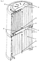
- Both top and bottom plate 3, 4, 3/4, 3/4a, 3/4b can comprise openings 35, 44, 45, see fig. 1 , 3 , 4 , 5 and 7 , for ventilation of the content of the packaging.
- the resulting ventilation effect in a single packaging system 1 or in stacked packaging systems is forced ventilation (so-called "chimney effect"), see fig. 4 and 5a .
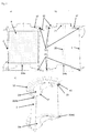
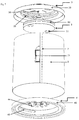
- the openings 35 and 45 are designed in a way that they are neighboured in stacked state of two or more packaging systems 1 and as the distance keepers 36 ensure that there is an airflow also to the openings 44, one can describe the total airflow in the following way: fresh air is entering from the bottom (e.g. through the pallet 9, see fig. 3 ) into the openings 44 and 45 of the bottom plate 4, see fig. 4 , then ascending at least between foil 2 and the packaged insulation material 6, but also through the insulation material 6 -especially when the insulation material 6 is fibrous and/or porous or cellular and/or tube-like, as is indicated in the upper left part of fig. 4 -, then leaving the first packaging system 1 through the openings 35 of the top plate 3.
- the air then can move through openings 45 of the bottom plate 4 of the next packaging or through the gap between the top and bottom plates 3, 4 provided by the distance keepers 36 into the central openings 44 of the bottom plate 4 of the next packaging, see fig. 5a , and so on. Finally, the air will escape through the opening 35 of the most upper top plate 3 of each stack.
- it is essential - besides UV, ozone and general physical and chemical stability, as mentioned above- to exhibit safe water drain properties. This needs to be provided without hampering the ventilation performance or the handling/stacking properties and is achieved in the present invention by a declination 37 being applied to at least the top plate 3 (see fig. 2 and 5b ).
- the design of the declination 37 is carried out in a way that water drain is always ensured because the uppermost part of outer rims or protrusions 30, 31 is always lower than the lowest edge of an opening for ventilation, e.g. 35, which is shown in fig. 5b by a virtual declination line 39.
- an overhang or a cantilever part 38 is applied at the section of at least the top plate 3 where the openings 35 are located (see fig. 5b and 6 ) and/or the openings 35 are arranged in a way that they face "downhill" the declination 37 (see fig. 11 ) and are shielded from draining off water by e.g. being placed into an uncontinuous protrusion or rib.
- the uppermost part of the top plate 3 where the distance keepers 36 are located can also comprise a declination, resulting in a slight dome shape, which is also helpful to prevent the uppermost part of the upper plate 3 being deformed of compressed when stacking the packaging systems 1, as such corrugation could have a negative effect (reducing the gap between the plates) on the ventilation through the openings 44.
- the distance keepers 36 may comprise a simple complete or interrupted protrusion preferably following the outer shape of the packaging 1 -see fig. 11 - and/or may comprise preferably radial bars or ribs, see fig. 1 .
- the top plate 3 and/or the bottom plate 4 can be connected to the foil 2 by hinges, latches etc. -46, see fig. 5b - to allow easy opening and closing of the packaging system 1, or the plates may be connected to each other by a separate connection -e.g. a bar or pillar 48, see fig. 8 - not necessarily being integral part of the foil 2, where again at least the top plate 3 may show a hinge 46 together with the connection 48.
- One of the top/bottom plate 3 or 4, preferably the top plate 3, can comprise a closed space generated by an insert 5, see fig. 1 and 7 , which is fixed to the plate by means of adhesion (glue, tape etc.) or welding (UHF, temperature etc.) or mechanically (by buttons, zip fasteners, hook and loop fasteners, snap-lock closure etc.) over the full distance or only partially.
- the insert 5 can also be fixed to the plate by a hinge and may comprise openings 50, or handles, or the like, for easily lifting it off the plate.
- the top or bottom plate and insert 5 will form a space where additional goods can be stored, such as papers, labels, instructions for use, service products, such as tape, glue, metal parts etc.
- This space can be designed weather- or waterproof or even airtight.
- the space formed by the top plate 3 and the insert 5 can also be accessible from the top by transforming the cap on the top plate 3 into a lid and e.g. providing it with a hinge and sealing items.
- the grooves and protrusions -31,41,42 see fig. 1 ; 33,43 see fig. 2 - are intended to stabilize the stack, but also the single packaging system 1 acting as reinforcing ribs. They can be of round or rectangular shape, with parallel walls or preferably showing slight cone shape to provide better sliding of one piece (plate) into or onto the other.
- Fig. 5 shows a possible basic embodiment of a groove/protrusion configuration.
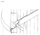
- Fig. 6 schematically shows other embodiments of the configuration: e.g. fig. 6a demonstrates that the rim 30 of the top plate 3 can be designed as an extended rim 30b to provide an outer guide for the rim 40 of the bottom plate 4.
- the inner walls of the rims can also be extended for higher stability and better guiding 30a,40a.
- Fig 6b shows in addition that also inner walls - e.g. 30a- can be extended to form a rib 30c.
- the inner walls 30a,40a being longer than the outer rims 40,30 resulting in a virtual declination 49 -see fig. 6a - provide improved weather resistance, as water could not penetrate even when the packaging 1 is exposed to heavy rain and would show no sealed rim/foil gap. This would mean in practice, that even an already opened packaging would still be rainproof if just being assembled again.
- the insulation material 6 to be packaged or wrapped or stored can be rigid or compressible. Some benefits of the packaging can only be applied on compressible materials (see below), however, the ventilation is beneficial for all kinds of material.
- the insulation material 6 can be of lamellar (mat-like) or tubular or any other shape, and can be placed horizontally or vertically into the packaging 1. Vertical placing is preferred for tubular shape materials, such as rolled mats or tubes. Separating materials, such as paper, tissue etc. can be placed between the layers of individual articles of the insulation material 6, as well as additional individual wrappings or packaging can be applied.
- the insulation material 6 can be packed into the foil 2 tightly or loosely, if necessary also leaving space in the center of the packaging for optimized ventilation (see e.g. fig. 3 and 4 ).
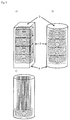
- the insulation material 6 can also be packed into the foil 2 in individual packaging, see fig. 9 . Different insulation materials 6 may also be packed together into the foil 2, see fig. 9c .
- the packaging 1 comprises according to one embodiment a handle 71, see fig. 7 and fig. 8 , which is preferably foldable or retractable and which can be applied on the top of the top plate 3 -preferably retractable into a groove not to disturb the ventilation process- or at the side of the packaging, e.g. welded, glued or riveted into the overlap of the foil 2 by means of connections 7 or 8.
- the handle 71 can also be formed in a way that at a part of the outer overlap 7 of the foil 2 is rolled back / anti-clockwise to its original rolling direction and fixed in rolled state, e.g. by adhesion spots 8, creating a handle bar 72.
- the handle bar comprises openings 75 that can e.g. be punched through the remaining not rolled overlap 7 to obtain a better grip, see fig. 11 .
- the insert 5 or any other part of the top plate 3 and/or the bottom plate 4 can be designed in a way that tightly to loosely fixing tubular shaped insulation material 6 -e.g. mat rolls or tubes- is achieved, e.g. to prevent it from moving or getting damage during transport, see fig. 10 a,b.
- tubular shaped insulation material 6 cone extensions 53 and/or cylindrical extensions 54 -if required in stepped cone form 54a- of the insert 5 -which may show an enlarged base plate 52 to host a larger number of extensions- will protrude into the opening of the tubular shape material at least from the top, but may also protrude from the bottom, e.g. from an inlay plate or an extension of the bottom plate 4.
- Such configuration is very beneficial for storing and transporting sensitive insulation materials 6, such as foamed glass or elastomeric foam.
- sensitive insulation materials 6 such as foamed glass or elastomeric foam.
- the tubular shape insulation materials can even be packaged as single items, which makes a lot of sense e.g. for big foamed glass shells and half shells and for large diameter elastomeric tubes.
- fig. 10c shows how this is achieved by using extended flaps 55 of the plate which show grooves and/or indentations and/or hinges 56 in the respective intervals and which then can be attached to the packaging diameter by simply bending the flaps and the fixing the excess length to the foil 2 as described above for rims 30 or flaps 32.
- the flaps 55 can be arranged in a shingle like manner or possible gaps can be sealed by tape etc.
- the top plate 3 and/or the bottom plate 4 may show grooves and/or rims 31,33,41,42,43 in the respective intervals. Excess length then can be cut off, facilitated by weakening or embossing the plate on the outer next to a rim or groove.
- the packaging system 1 can comprise reinforcing structures inside the foil 2, such as cylindrical or cone or rectangular or star shape columns 20, see fig. 2a , 3 , 11 and 12 , which show further reinforcing structures 21, see fig. 2a , and/or ventilation openings 25, see fig. 3 .
- the reinforcing structures 20 can be hollow to enable to drain the central part of the top plate 3, see fig. 12 .
- the foil 2 shows a minimum thickness of 100 micron
- the top plates 3 and bottom plates 4 show a thickness of at least 150 micron at their thinnest point.
- any of the packaging 1 component 2,3,4,5 can comprise additional layers, reinforcements, surface structures such as openings, grooves, slots; or printings or labels or any of the combinations thereof.
- the packaging system 1 itself can be wrapped again with tape, foil or shrink-warp or be furnished with any other outer packaging to further protect the system and/or to bundle several packaging systems, e.g. on a pallet 9 for space-saving transport.
- the foil 2 can be manufactured by calendaring, extrusion, film blowing etc., depending on the material.
- the plates 3,4 as well as some other parts, like the insert 5, handles 9, hinges 46 etc. can be manufactured by deep-drawing or casting / moulding processes, followed by embossing, (die-)cutting etc.
- the openings 35,45 can be obtained by die-cutting a premanufactured plate, or the can be obtained directly through respective mould construction in moulding process.
- At least a four-part mould is required, optionally with a collapsing core for easier demoulding of the undercut inside the overhang 38.
- the openings 35,45 cannot be arranged entirely around the plates' circumference, as can be seen in fig. 7 and 8 .
- brittle materials like foamed glass or PIR
- compressible materials like elastomeric foam
- the packaging is very versatile in size, volume, geometry and material, and therefore can be used for wrapping any insulation material, such as fibres (mineral, glass, felt, coconut fiber, hemp etc.), duromerics (polyurethanes/PUR/PIR, melamines, phenolics etc.), elastomerics (rubbers, TPEs), thermoplasts (polyolefins, technical thermoplasts etc.) and expanded metals or foamed glass.
- insulation material such as fibres (mineral, glass, felt, coconut fiber, hemp etc.), duromerics (polyurethanes/PUR/PIR, melamines, phenolics etc.), elastomerics (rubbers, TPEs), thermoplasts (polyolefins, technical thermoplasts etc.) and expanded metals or foamed glass.
- geometry i.e. the top view contour
- width and height of the packaging can be adapted to 1) the insulation material 6 to be packaged (material, dimensions etc.) and 2) to the requirements for storage and transport (pallet size, container / truck shipping space etc.).
- the versatility of the packaging system allows to store and transport the insulation material 6 in loose to very compressed state, depending on the material's properties.
- expanded polymeric material such as polyethylene or elastomeric mats
- a slight compression by the foil 2 of the packaging 1 could prevent this uneven shrinkage by applying the same compression and thus friction ratio over the entire mat roll.
- insulation materials 6 can be individually wrapped and fixed using parallel wall, cone or reverse cone geometry of the foil 2, respectively.
- the packaging can be opened easily, by opening the foil 2 or removing top or bottom plate 3,4, (e.g. by tearing at handles 71,72), and that individually packaged parts can be withdrawn without complete removal of the foil or plates.
Landscapes
- Engineering & Computer Science (AREA)
- Mechanical Engineering (AREA)
- Packages (AREA)
- Buffer Packaging (AREA)
Priority Applications (6)
| Application Number | Priority Date | Filing Date | Title |
|---|---|---|---|
| PL13198937T PL2886489T3 (pl) | 2013-12-20 | 2013-12-20 | System opakowaniowy do materiałów izolacyjnych |
| EP13198937.8A EP2886489B1 (en) | 2013-12-20 | 2013-12-20 | Packaging system for insulation materials |
| ZA2014/09137A ZA201409137B (en) | 2013-12-20 | 2014-12-11 | Packaging system for insulation materials |
| MX2014015605A MX350886B (es) | 2013-12-20 | 2014-12-17 | Sistema de embalaje para materiales aislantes. |
| RU2014151725A RU2662190C2 (ru) | 2013-12-20 | 2014-12-19 | Упаковочная система для изоляционных материалов |
| US14/578,180 US9878838B2 (en) | 2013-12-20 | 2014-12-19 | Packaging system for insulation materials |
Applications Claiming Priority (1)
| Application Number | Priority Date | Filing Date | Title |
|---|---|---|---|
| EP13198937.8A EP2886489B1 (en) | 2013-12-20 | 2013-12-20 | Packaging system for insulation materials |
Publications (2)
| Publication Number | Publication Date |
|---|---|
| EP2886489A1 EP2886489A1 (en) | 2015-06-24 |
| EP2886489B1 true EP2886489B1 (en) | 2016-11-02 |
Family
ID=49920042
Family Applications (1)
| Application Number | Title | Priority Date | Filing Date |
|---|---|---|---|
| EP13198937.8A Active EP2886489B1 (en) | 2013-12-20 | 2013-12-20 | Packaging system for insulation materials |
Country Status (6)
| Country | Link |
|---|---|
| US (1) | US9878838B2 (pl) |
| EP (1) | EP2886489B1 (pl) |
| MX (1) | MX350886B (pl) |
| PL (1) | PL2886489T3 (pl) |
| RU (1) | RU2662190C2 (pl) |
| ZA (1) | ZA201409137B (pl) |
Families Citing this family (4)
| Publication number | Priority date | Publication date | Assignee | Title |
|---|---|---|---|---|
| US11731826B2 (en) | 2021-10-22 | 2023-08-22 | Packaging Technology Group, Llc | Recyclable, thermally insulated shipping container with packed, loose-fill organic insulation |
| US11953262B2 (en) | 2013-05-10 | 2024-04-09 | Packaging Technology Group, Llc | Recyclable, thermally insulated shipping container with packed, loose-fill organic insulation and PCM bladder insert |
| DE102018209421A1 (de) * | 2018-06-13 | 2019-12-19 | Albrecht Bäumer GmbH & Co.KG Spezialmaschinenfabrik | Vorrichtung zum Lagern und Transport von großvolumigen Schaumstoffblöcken |
| US12304168B2 (en) | 2021-10-22 | 2025-05-20 | Packaging Technology Group, Llc | Method of filling an insulated shipping container with loose-fill organic insulation |
Family Cites Families (24)
| Publication number | Priority date | Publication date | Assignee | Title |
|---|---|---|---|---|
| US123824A (en) * | 1872-02-20 | Improvement in baling short-cut hay and straw | ||
| US3587201A (en) | 1968-07-10 | 1971-06-28 | Johns Manville | Pipe-insulation packaging system |
| US3696966A (en) * | 1971-01-22 | 1972-10-10 | Vanguard Industries | Device for handling baby chicks and the like |
| GB1418882A (en) | 1972-01-24 | 1975-12-24 | Cape Insulation Ltd | Packaging thermal insulation |
| US3889444A (en) | 1973-01-11 | 1975-06-17 | Certain Teed Prod Corp | Method for packaging fiber glass insulation |
| US3955705A (en) * | 1973-01-17 | 1976-05-11 | Greif Bros. Corporation | Plastic drum |
| US4074827A (en) * | 1976-08-31 | 1978-02-21 | Labe Iii Jacob | Multi-purpose closure for containers |
| US4535587A (en) * | 1979-07-09 | 1985-08-20 | Isover Saint-Gobain | Multi-roll package of compressible materials |
| DK153934C (da) | 1986-12-22 | 1993-05-03 | Rockwool Int | Fremgangsmaade og apparat til emballering af et antal pakker af et inden for givne graenser elastisk isoleringsmateriale |
| US4909392A (en) * | 1988-09-01 | 1990-03-20 | Aspen, Inc. | Liquid container |
| FR2696713A1 (fr) | 1992-10-08 | 1994-04-15 | Saint Gobain Isover | Procédé et dispositif pour le conditionnement de produits isolants compressibles. |
| US5512346A (en) | 1994-09-21 | 1996-04-30 | Owens-Corning Fiberglas Technology, Inc. | Insulation assembly for compressible insulation material |
| GB9509310D0 (en) * | 1995-05-06 | 1995-06-28 | Rover Group | Container for an article |
| DE29825177U1 (de) | 1998-09-18 | 2005-10-27 | Deutsche Rockwool Mineralwoll Gmbh + Co Ohg | Transporteinheit |
| BE1014338A3 (fr) | 2001-08-10 | 2003-09-02 | Alcopor Knauf Technology Ag | Produit d'isolation en laine minerale. |
| DE10317392A1 (de) * | 2003-04-15 | 2004-11-04 | Saint-Gobain Isover G+H Ag | Großgebinde für Transport und Lagerung von Dämmstoffelementen sowie Module aus Dämmstoffelementen hierfür |
| US20050157961A1 (en) * | 2004-01-21 | 2005-07-21 | Dudley Langston | Vented package |
| US20050260368A1 (en) | 2004-05-18 | 2005-11-24 | Ruid John O | Packaging for insulation products |
| WO2006102893A1 (en) | 2005-03-29 | 2006-10-05 | Rockwool International A/S | An insulation product package and a method for packaging an insulation product |
| RU59549U1 (ru) * | 2006-06-21 | 2006-12-27 | Ирина Эдуардовна Гудович | Упаковка детских изделий (варианты) |
| WO2010046098A1 (en) * | 2008-10-24 | 2010-04-29 | Saudi Basic Industries Corporation | Multi layer film |
| GB201020173D0 (en) | 2010-11-29 | 2011-01-12 | Knauf Insulation | Thermal and/or acoustic insulation packaging |
| US20120285951A1 (en) * | 2011-05-11 | 2012-11-15 | Cavalcante Mauricio D | Collapsible crate |
| US20130067861A1 (en) | 2011-09-16 | 2013-03-21 | Owens Corning Intellectual Capital, Llc | Packaging to improve shelflife of insulation products |
-
2013
- 2013-12-20 PL PL13198937T patent/PL2886489T3/pl unknown
- 2013-12-20 EP EP13198937.8A patent/EP2886489B1/en active Active
-
2014
- 2014-12-11 ZA ZA2014/09137A patent/ZA201409137B/en unknown
- 2014-12-17 MX MX2014015605A patent/MX350886B/es active IP Right Grant
- 2014-12-19 RU RU2014151725A patent/RU2662190C2/ru active
- 2014-12-19 US US14/578,180 patent/US9878838B2/en not_active Expired - Fee Related
Also Published As
| Publication number | Publication date |
|---|---|
| PL2886489T3 (pl) | 2017-06-30 |
| MX2014015605A (es) | 2015-07-06 |
| MX350886B (es) | 2017-09-25 |
| RU2014151725A (ru) | 2016-07-10 |
| ZA201409137B (en) | 2015-09-30 |
| RU2014151725A3 (pl) | 2018-06-07 |
| RU2662190C2 (ru) | 2018-07-24 |
| US20150232249A1 (en) | 2015-08-20 |
| US9878838B2 (en) | 2018-01-30 |
| EP2886489A1 (en) | 2015-06-24 |
Similar Documents
| Publication | Publication Date | Title |
|---|---|---|
| US9878838B2 (en) | Packaging system for insulation materials | |
| US9944449B2 (en) | Thermally insulated package | |
| AU2023201413A1 (en) | Shipping container with compostable insulation | |
| US10035638B1 (en) | Retention package with article-loading aperture and method of making and using the same | |
| US10124948B2 (en) | Angle edge protector | |
| US20180282050A1 (en) | Insulated shipping container for works of art | |
| EP2883811B1 (en) | Thermally insulated package | |
| JP7457126B2 (ja) | 冷蔵庫用の包装構造および包装方法 | |
| JP5412628B2 (ja) | 農産物用コンテナ及びその内容器 | |
| US20130036707A1 (en) | Modular packing system | |
| US20070160801A1 (en) | Panel constructions and assemblies made therefrom | |
| CN217650027U (zh) | 一种高强度的环保包装纸箱 | |
| CA2691028C (en) | Extra strength u-board | |
| CN204548765U (zh) | 包装结构 | |
| US6805239B2 (en) | Support for large rolls of material | |
| JP4601272B2 (ja) | ロール状物保持具及びロール状物保持構造 | |
| KR20100012951U (ko) | 물류용 상자 | |
| US20230279683A1 (en) | Spa cover | |
| WO2019063051A1 (en) | TRANSPORT BOX | |
| JPH062940Y2 (ja) | 物品包装容器 | |
| KR20230155236A (ko) | 보온·보냉 및 완충기능을 갖는 포장박스 | |
| KR20190001327U (ko) | 엘씨디 필름용 포장상자 | |
| JPH0437105Y2 (pl) | ||
| KR20260020998A (ko) | 과일팩 | |
| JP2013075722A (ja) | 梱包体 |
Legal Events
| Date | Code | Title | Description |
|---|---|---|---|
| PUAI | Public reference made under article 153(3) epc to a published international application that has entered the european phase |
Free format text: ORIGINAL CODE: 0009012 |
|
| 17P | Request for examination filed |
Effective date: 20131220 |
|
| AK | Designated contracting states |
Kind code of ref document: A1 Designated state(s): AL AT BE BG CH CY CZ DE DK EE ES FI FR GB GR HR HU IE IS IT LI LT LU LV MC MK MT NL NO PL PT RO RS SE SI SK SM TR |
|
| AX | Request for extension of the european patent |
Extension state: BA ME |
|
| R17P | Request for examination filed (corrected) |
Effective date: 20151217 |
|
| RBV | Designated contracting states (corrected) |
Designated state(s): AL AT BE BG CH CY CZ DE DK EE ES FI FR GB GR HR HU IE IS IT LI LT LU LV MC MK MT NL NO PL PT RO RS SE SI SK SM TR |
|
| GRAP | Despatch of communication of intention to grant a patent |
Free format text: ORIGINAL CODE: EPIDOSNIGR1 |
|
| RIC1 | Information provided on ipc code assigned before grant |
Ipc: B65D 85/16 20060101AFI20160415BHEP |
|
| INTG | Intention to grant announced |
Effective date: 20160512 |
|
| GRAS | Grant fee paid |
Free format text: ORIGINAL CODE: EPIDOSNIGR3 |
|
| GRAA | (expected) grant |
Free format text: ORIGINAL CODE: 0009210 |
|
| AK | Designated contracting states |
Kind code of ref document: B1 Designated state(s): AL AT BE BG CH CY CZ DE DK EE ES FI FR GB GR HR HU IE IS IT LI LT LU LV MC MK MT NL NO PL PT RO RS SE SI SK SM TR |
|
| REG | Reference to a national code |
Ref country code: GB Ref legal event code: FG4D |
|
| RIN1 | Information on inventor provided before grant (corrected) |
Inventor name: KAIMANN, GEORG JOSEF Inventor name: KAISER, HUBERT Inventor name: WEIDINGER, JUERGEN GEORG |
|
| REG | Reference to a national code |
Ref country code: AT Ref legal event code: REF Ref document number: 841597 Country of ref document: AT Kind code of ref document: T Effective date: 20161115 Ref country code: CH Ref legal event code: EP |
|
| RIN2 | Information on inventor provided after grant (corrected) |
Inventor name: KAISER, HUBERT Inventor name: WEIDINGER, JUERGEN GEORG Inventor name: KAIMANN, GEORG JOSEF |
|
| REG | Reference to a national code |
Ref country code: DE Ref legal event code: R079 Ref document number: 602013013435 Country of ref document: DE Free format text: PREVIOUS MAIN CLASS: B65D0085160000 Ipc: B65D0085070000 |
|
| REG | Reference to a national code |
Ref country code: IE Ref legal event code: FG4D |
|
| REG | Reference to a national code |
Ref country code: DE Ref legal event code: R096 Ref document number: 602013013435 Country of ref document: DE |
|
| REG | Reference to a national code |
Ref country code: NL Ref legal event code: FP |
|
| REG | Reference to a national code |
Ref country code: FR Ref legal event code: PLFP Year of fee payment: 4 |
|
| PG25 | Lapsed in a contracting state [announced via postgrant information from national office to epo] |
Ref country code: LV Free format text: LAPSE BECAUSE OF FAILURE TO SUBMIT A TRANSLATION OF THE DESCRIPTION OR TO PAY THE FEE WITHIN THE PRESCRIBED TIME-LIMIT Effective date: 20161102 |
|
| REG | Reference to a national code |
Ref country code: LT Ref legal event code: MG4D |
|
| PG25 | Lapsed in a contracting state [announced via postgrant information from national office to epo] |
Ref country code: NO Free format text: LAPSE BECAUSE OF FAILURE TO SUBMIT A TRANSLATION OF THE DESCRIPTION OR TO PAY THE FEE WITHIN THE PRESCRIBED TIME-LIMIT Effective date: 20170202 Ref country code: LT Free format text: LAPSE BECAUSE OF FAILURE TO SUBMIT A TRANSLATION OF THE DESCRIPTION OR TO PAY THE FEE WITHIN THE PRESCRIBED TIME-LIMIT Effective date: 20161102 Ref country code: SE Free format text: LAPSE BECAUSE OF FAILURE TO SUBMIT A TRANSLATION OF THE DESCRIPTION OR TO PAY THE FEE WITHIN THE PRESCRIBED TIME-LIMIT Effective date: 20161102 Ref country code: GR Free format text: LAPSE BECAUSE OF FAILURE TO SUBMIT A TRANSLATION OF THE DESCRIPTION OR TO PAY THE FEE WITHIN THE PRESCRIBED TIME-LIMIT Effective date: 20170203 |
|
| PG25 | Lapsed in a contracting state [announced via postgrant information from national office to epo] |
Ref country code: IS Free format text: LAPSE BECAUSE OF FAILURE TO SUBMIT A TRANSLATION OF THE DESCRIPTION OR TO PAY THE FEE WITHIN THE PRESCRIBED TIME-LIMIT Effective date: 20170302 Ref country code: RS Free format text: LAPSE BECAUSE OF FAILURE TO SUBMIT A TRANSLATION OF THE DESCRIPTION OR TO PAY THE FEE WITHIN THE PRESCRIBED TIME-LIMIT Effective date: 20161102 Ref country code: ES Free format text: LAPSE BECAUSE OF FAILURE TO SUBMIT A TRANSLATION OF THE DESCRIPTION OR TO PAY THE FEE WITHIN THE PRESCRIBED TIME-LIMIT Effective date: 20161102 Ref country code: PT Free format text: LAPSE BECAUSE OF FAILURE TO SUBMIT A TRANSLATION OF THE DESCRIPTION OR TO PAY THE FEE WITHIN THE PRESCRIBED TIME-LIMIT Effective date: 20170302 Ref country code: FI Free format text: LAPSE BECAUSE OF FAILURE TO SUBMIT A TRANSLATION OF THE DESCRIPTION OR TO PAY THE FEE WITHIN THE PRESCRIBED TIME-LIMIT Effective date: 20161102 Ref country code: HR Free format text: LAPSE BECAUSE OF FAILURE TO SUBMIT A TRANSLATION OF THE DESCRIPTION OR TO PAY THE FEE WITHIN THE PRESCRIBED TIME-LIMIT Effective date: 20161102 |
|
| PG25 | Lapsed in a contracting state [announced via postgrant information from national office to epo] |
Ref country code: CZ Free format text: LAPSE BECAUSE OF FAILURE TO SUBMIT A TRANSLATION OF THE DESCRIPTION OR TO PAY THE FEE WITHIN THE PRESCRIBED TIME-LIMIT Effective date: 20161102 Ref country code: SK Free format text: LAPSE BECAUSE OF FAILURE TO SUBMIT A TRANSLATION OF THE DESCRIPTION OR TO PAY THE FEE WITHIN THE PRESCRIBED TIME-LIMIT Effective date: 20161102 Ref country code: EE Free format text: LAPSE BECAUSE OF FAILURE TO SUBMIT A TRANSLATION OF THE DESCRIPTION OR TO PAY THE FEE WITHIN THE PRESCRIBED TIME-LIMIT Effective date: 20161102 Ref country code: RO Free format text: LAPSE BECAUSE OF FAILURE TO SUBMIT A TRANSLATION OF THE DESCRIPTION OR TO PAY THE FEE WITHIN THE PRESCRIBED TIME-LIMIT Effective date: 20161102 Ref country code: DK Free format text: LAPSE BECAUSE OF FAILURE TO SUBMIT A TRANSLATION OF THE DESCRIPTION OR TO PAY THE FEE WITHIN THE PRESCRIBED TIME-LIMIT Effective date: 20161102 |
|
| REG | Reference to a national code |
Ref country code: DE Ref legal event code: R097 Ref document number: 602013013435 Country of ref document: DE |
|
| PG25 | Lapsed in a contracting state [announced via postgrant information from national office to epo] |
Ref country code: BG Free format text: LAPSE BECAUSE OF FAILURE TO SUBMIT A TRANSLATION OF THE DESCRIPTION OR TO PAY THE FEE WITHIN THE PRESCRIBED TIME-LIMIT Effective date: 20170202 Ref country code: SM Free format text: LAPSE BECAUSE OF FAILURE TO SUBMIT A TRANSLATION OF THE DESCRIPTION OR TO PAY THE FEE WITHIN THE PRESCRIBED TIME-LIMIT Effective date: 20161102 |
|
| PLBE | No opposition filed within time limit |
Free format text: ORIGINAL CODE: 0009261 |
|
| STAA | Information on the status of an ep patent application or granted ep patent |
Free format text: STATUS: NO OPPOSITION FILED WITHIN TIME LIMIT |
|
| PG25 | Lapsed in a contracting state [announced via postgrant information from national office to epo] |
Ref country code: MC Free format text: LAPSE BECAUSE OF FAILURE TO SUBMIT A TRANSLATION OF THE DESCRIPTION OR TO PAY THE FEE WITHIN THE PRESCRIBED TIME-LIMIT Effective date: 20161102 |
|
| 26N | No opposition filed |
Effective date: 20170803 |
|
| PG25 | Lapsed in a contracting state [announced via postgrant information from national office to epo] |
Ref country code: SI Free format text: LAPSE BECAUSE OF FAILURE TO SUBMIT A TRANSLATION OF THE DESCRIPTION OR TO PAY THE FEE WITHIN THE PRESCRIBED TIME-LIMIT Effective date: 20161102 |
|
| REG | Reference to a national code |
Ref country code: FR Ref legal event code: PLFP Year of fee payment: 5 |
|
| PG25 | Lapsed in a contracting state [announced via postgrant information from national office to epo] |
Ref country code: HU Free format text: LAPSE BECAUSE OF FAILURE TO SUBMIT A TRANSLATION OF THE DESCRIPTION OR TO PAY THE FEE WITHIN THE PRESCRIBED TIME-LIMIT; INVALID AB INITIO Effective date: 20131220 |
|
| PG25 | Lapsed in a contracting state [announced via postgrant information from national office to epo] |
Ref country code: MK Free format text: LAPSE BECAUSE OF FAILURE TO SUBMIT A TRANSLATION OF THE DESCRIPTION OR TO PAY THE FEE WITHIN THE PRESCRIBED TIME-LIMIT Effective date: 20161102 Ref country code: CY Free format text: LAPSE BECAUSE OF FAILURE TO SUBMIT A TRANSLATION OF THE DESCRIPTION OR TO PAY THE FEE WITHIN THE PRESCRIBED TIME-LIMIT Effective date: 20161102 |
|
| PG25 | Lapsed in a contracting state [announced via postgrant information from national office to epo] |
Ref country code: MT Free format text: LAPSE BECAUSE OF NON-PAYMENT OF DUE FEES Effective date: 20161220 |
|
| PG25 | Lapsed in a contracting state [announced via postgrant information from national office to epo] |
Ref country code: TR Free format text: LAPSE BECAUSE OF FAILURE TO SUBMIT A TRANSLATION OF THE DESCRIPTION OR TO PAY THE FEE WITHIN THE PRESCRIBED TIME-LIMIT Effective date: 20161102 |
|
| REG | Reference to a national code |
Ref country code: AT Ref legal event code: UEP Ref document number: 841597 Country of ref document: AT Kind code of ref document: T Effective date: 20161102 |
|
| PG25 | Lapsed in a contracting state [announced via postgrant information from national office to epo] |
Ref country code: AL Free format text: LAPSE BECAUSE OF FAILURE TO SUBMIT A TRANSLATION OF THE DESCRIPTION OR TO PAY THE FEE WITHIN THE PRESCRIBED TIME-LIMIT Effective date: 20161102 |
|
| PGFP | Annual fee paid to national office [announced via postgrant information from national office to epo] |
Ref country code: GB Payment date: 20201209 Year of fee payment: 8 Ref country code: IE Payment date: 20201209 Year of fee payment: 8 |
|
| PGFP | Annual fee paid to national office [announced via postgrant information from national office to epo] |
Ref country code: PL Payment date: 20201118 Year of fee payment: 8 |
|
| PGFP | Annual fee paid to national office [announced via postgrant information from national office to epo] |
Ref country code: LU Payment date: 20201210 Year of fee payment: 8 |
|
| GBPC | Gb: european patent ceased through non-payment of renewal fee |
Effective date: 20211220 |
|
| PG25 | Lapsed in a contracting state [announced via postgrant information from national office to epo] |
Ref country code: LU Free format text: LAPSE BECAUSE OF NON-PAYMENT OF DUE FEES Effective date: 20211220 Ref country code: IE Free format text: LAPSE BECAUSE OF NON-PAYMENT OF DUE FEES Effective date: 20211220 Ref country code: GB Free format text: LAPSE BECAUSE OF NON-PAYMENT OF DUE FEES Effective date: 20211220 |
|
| PG25 | Lapsed in a contracting state [announced via postgrant information from national office to epo] |
Ref country code: PL Free format text: LAPSE BECAUSE OF NON-PAYMENT OF DUE FEES Effective date: 20211220 |
|
| P01 | Opt-out of the competence of the unified patent court (upc) registered |
Effective date: 20230424 |
|
| PGFP | Annual fee paid to national office [announced via postgrant information from national office to epo] |
Ref country code: NL Payment date: 20241120 Year of fee payment: 12 |
|
| PGFP | Annual fee paid to national office [announced via postgrant information from national office to epo] |
Ref country code: DE Payment date: 20241029 Year of fee payment: 12 |
|
| PGFP | Annual fee paid to national office [announced via postgrant information from national office to epo] |
Ref country code: BE Payment date: 20241120 Year of fee payment: 12 |
|
| PGFP | Annual fee paid to national office [announced via postgrant information from national office to epo] |
Ref country code: FR Payment date: 20241111 Year of fee payment: 12 |
|
| PGFP | Annual fee paid to national office [announced via postgrant information from national office to epo] |
Ref country code: AT Payment date: 20241126 Year of fee payment: 12 |
|
| PGFP | Annual fee paid to national office [announced via postgrant information from national office to epo] |
Ref country code: IT Payment date: 20241112 Year of fee payment: 12 |
|
| PGFP | Annual fee paid to national office [announced via postgrant information from national office to epo] |
Ref country code: CH Payment date: 20250101 Year of fee payment: 12 |