EP2886441A2 - Passive anti-rolling tank - Google Patents
Passive anti-rolling tank Download PDFInfo
- Publication number
- EP2886441A2 EP2886441A2 EP14189059.0A EP14189059A EP2886441A2 EP 2886441 A2 EP2886441 A2 EP 2886441A2 EP 14189059 A EP14189059 A EP 14189059A EP 2886441 A2 EP2886441 A2 EP 2886441A2
- Authority
- EP
- European Patent Office
- Prior art keywords
- rolling
- passive anti
- protruding
- bottom wall
- fluid
- Prior art date
- Legal status (The legal status is an assumption and is not a legal conclusion. Google has not performed a legal analysis and makes no representation as to the accuracy of the status listed.)
- Withdrawn
Links
- 238000005096 rolling process Methods 0.000 title claims abstract description 60
- 239000012530 fluid Substances 0.000 claims abstract description 33
- 230000003247 decreasing effect Effects 0.000 claims description 4
- 230000000694 effects Effects 0.000 description 9
- 238000000034 method Methods 0.000 description 2
- 230000002401 inhibitory effect Effects 0.000 description 1
- 238000012986 modification Methods 0.000 description 1
- 230000004048 modification Effects 0.000 description 1
- 235000015096 spirit Nutrition 0.000 description 1
Images

Classifications
-
- B—PERFORMING OPERATIONS; TRANSPORTING
- B63—SHIPS OR OTHER WATERBORNE VESSELS; RELATED EQUIPMENT
- B63B—SHIPS OR OTHER WATERBORNE VESSELS; EQUIPMENT FOR SHIPPING
- B63B39/00—Equipment to decrease pitch, roll, or like unwanted vessel movements; Apparatus for indicating vessel attitude
- B63B39/02—Equipment to decrease pitch, roll, or like unwanted vessel movements; Apparatus for indicating vessel attitude to decrease vessel movements by displacement of masses
- B63B39/03—Equipment to decrease pitch, roll, or like unwanted vessel movements; Apparatus for indicating vessel attitude to decrease vessel movements by displacement of masses by transferring liquids
-
- B—PERFORMING OPERATIONS; TRANSPORTING
- B63—SHIPS OR OTHER WATERBORNE VESSELS; RELATED EQUIPMENT
- B63B—SHIPS OR OTHER WATERBORNE VESSELS; EQUIPMENT FOR SHIPPING
- B63B43/00—Improving safety of vessels, e.g. damage control, not otherwise provided for
- B63B43/02—Improving safety of vessels, e.g. damage control, not otherwise provided for reducing risk of capsizing or sinking
- B63B43/04—Improving safety of vessels, e.g. damage control, not otherwise provided for reducing risk of capsizing or sinking by improving stability
- B63B43/06—Improving safety of vessels, e.g. damage control, not otherwise provided for reducing risk of capsizing or sinking by improving stability using ballast tanks
Definitions
- the present disclosure relates to a passive anti-rolling tank, and more particularly, to a passive anti-rolling tank in which a protruding bottom wall is formed, such that an anti-rolling effect of the same level may be achieved with a smaller amount of fluid.
- anti-rolling tanks may be classified into a passive type, in which power is not transferred from an exterior and separate control is not performed, and an active type, in which power is transferred from an exterior or separate control is performed.
- the passive type anti-rolling tank has been applied to a number of ships since Frahm developed a U-tube type anti-rolling tank in 1911 and Stigter formulated a theory on the U-tube type anti-rolling tank and performed analysis thereof.
- a reference document related with the present disclosure is Korean Unexamined Patent Publication No. 10-2011-0101870 (dated September 16, 2011 ), in which a rolling-inhibiting type ship and a method for controlling the rolling of a ship are disclosed.
- Various embodiments are directed to a passive anti-rolling tank which may achieve an anti-rolling effect by using a smaller amount of fluid.
- a passive anti-rolling tank may include: a tank body providing a closed space that accommodates free-surface fluid; and a protruding bottom wall formed on a bottom of the tank body to have a protruding shape, such that a greater amount of fluid can be accommodated in side portions of the tank body.
- the protruding bottom wall may have a left-right symmetrical shape, and may be formed such that a depth of the fluid accommodated in the tank body increases from a center portion to the side portions of the tank body when the tank body is oriented in a horizontal state.
- the protruding bottom wall may be formed to have inclined surfaces that are inclined downward from the center portion to the side portions, or a curved surface that allows a depth of the fluid to increase from the center portion to the side portions thereof.
- the protruding bottom wall may include a planar protruding wall which is formed on a center portion of the bottom of the tank body such that an amount of the fluid which may be stored in the center portion is decreased.
- the protruding bottom wall may further include inclined walls or curved walls which are formed on both sides of the planar protruding wall.
- the protruding bottom wall may be formed to have a convex curved surface and concave curved surfaces.
- an improved anti-rolling effect may be achieved from the same weight, or an anti-rolling effect of the same level may be achieved from a smaller weight.
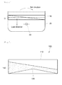
- FIG. 1 is a view illustrating a conventional passive anti-rolling tank.
- a passive anti-rolling tank 10 is formed in a hull 20 of a floating structure in such a way as to be left-right symmetrical in the port and starboard directions. Also, the passive anti-rolling tank 10 defines a closed space which accommodates fluid 15, and the fluid 15 is stored to have a free surface.
- the passive anti-rolling tank 10 is disposed in a shape which is left-right symmetrical with respect to a center of rotation 30 of the hull 20. Further, although the passive anti-rolling tank 10 may be positioned above the center of rotation 30 of the hull 20, as shown in the drawing, it is to be noted that the position of the passive anti-rolling tank 10 is not limited to this position, and may be changed according to the shape of the hull 20, and so on.
- FIG. 2 is a view illustrating a passive anti-rolling tank in accordance with a first embodiment of the present disclosure.
- a passive anti-rolling tank 100 in accordance with a first embodiment includes a tank body 110 which provides a closed space for accommodating free-surface fluid 150, and a protruding bottom wall 130 which is formed into a shape which protrudes from the bottom of the tank body 110 such that a larger amount of the fluid 150 is accommodated in the side portions rather than in the center portion of the tank body 110.
- the protruding bottom wall 130 may be fabricated separately from the tank body 110 and be attached to the bottom of the tank body 110, or may be fabricated integrally with the bottom of the tank body 110.
- the tank body 110 provides the closed space which accommodates the fluid 150.
- the fluid 150 is stored in the tank body 110 to have a free surface, and induces a moment according to rolling.
- the passive anti-rolling tank 100 plays the role of reducing the rolling of a hull, attributable to the phase difference between the rolling moment of the tank body 110 and the moment of the fluid 150 accommodated in the tank body 110 that is induced by the free-surface movement of the fluid 150.
- the embodiment of the present disclosure is to change the shape of the passive anti-rolling tank 100 and thereby induce a larger moment with a smaller amount of the fluid 150.
- the embodiment of the present disclosure is to provide the shape of the protruding bottom wall 130 which allows the load acting point of the fluid 150 to move outward.
- the protruding bottom wall 130 has a left-right symmetrical shape. This is to achieve a uniform anti-rolling effect with respect to leftward and rightward rolling.
- the protruding bottom wall 130 may be formed in such a manner that the depth of the fluid 150 at the center portion of the tank body 110 is less than the depth of the fluid 150 at the side portions of the tank body 110 in the state in which the tank body 110 is oriented horizontally. That is to say, the protruding bottom wall 130 may have a shape such that its center portion protrudes upward.
- FIG. 2 shows that the protruding bottom wall 130 is formed to have inclined surfaces which are inclined downward from the center portion to the side portions.
- the amounts of the fluid 150 which is stored in the center portion and the side portions are different from each other, attributable to the shape of the protruding bottom wall 130.
- an anti-rolling effect may be achieved using a smaller amount of the fluid 150.
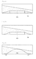
- FIG. 3 is a view illustrating a passive anti-rolling tank in accordance with a second embodiment of the present disclosure
- FIG. 4 is a view illustrating a passive anti-rolling tank in accordance with a third embodiment of the present disclosure.
- the second embodiment of FIG. 3 shows that a protruding bottom wall 131 is formed into a convex curved surface shape
- the third embodiment of FIG. 4 shows that a protruding bottom wall 132 is formed to have concave curved surface shapes.
- FIG. 5 is a view illustrating a passive anti-rolling tank in accordance with a fourth embodiment of the present disclosure.
- the fourth embodiment of FIG. 5 shows that a planar protruding wall 133 is formed on the center portion of the bottom of a tank body. Attributable to the fact that the planar protruding wall 133 is formed on the center portion of the bottom of the tank body, an amount of fluid which may be stored in the center portion may be decreased, and thus, an effect that the load acting point of the fluid moves outward may be achieved.
- FIG. 6 is a view illustrating a passive anti-rolling tank in accordance with a fifth embodiment of the present disclosure
- FIG. 7 is a view illustrating a passive anti-rolling tank in accordance with a sixth embodiment of the present disclosure.
- the fifth embodiment of FIG. 6 shows that a protruding bottom wall is formed in a shape in which inclined walls 134 are connected to both sides of a planar protruding wall 133
- the sixth embodiment of FIG. 7 shows that a protruding bottom wall is formed in a shape in which curved walls 135 are connected to both sides of a planar protruding wall 133.
- FIG. 8 is a view illustrating a passive anti-rolling tank in accordance with a seventh embodiment of the present disclosure.
- the seventh embodiment shows that a protruding bottom wall is formed to have a convex curved surface shape 136 in the center portion thereof and concave curved surface shapes 137 on both sides of the convex curved surface shape 136.
- an amount of fluid necessary to achieve a predetermined level of anti-rolling effect may be reduced, whereby the overall weight may be decreased.
Landscapes
- Chemical & Material Sciences (AREA)
- Engineering & Computer Science (AREA)
- Combustion & Propulsion (AREA)
- Mechanical Engineering (AREA)
- Ocean & Marine Engineering (AREA)
- Filling Or Discharging Of Gas Storage Vessels (AREA)
- Treatment Of Water By Ion Exchange (AREA)
- Rolling Contact Bearings (AREA)
- Sewage (AREA)
Abstract
Description
- The present disclosure relates to a passive anti-rolling tank, and more particularly, to a passive anti-rolling tank in which a protruding bottom wall is formed, such that an anti-rolling effect of the same level may be achieved with a smaller amount of fluid.
- In general, anti-rolling tanks may be classified into a passive type, in which power is not transferred from an exterior and separate control is not performed, and an active type, in which power is transferred from an exterior or separate control is performed.
- The passive type anti-rolling tank has been applied to a number of ships since Frahm developed a U-tube type anti-rolling tank in 1911 and Stigter formulated a theory on the U-tube type anti-rolling tank and performed analysis thereof.
- A reference document related with the present disclosure is Korean Unexamined Patent Publication No.
10-2011-0101870 (dated September 16, 2011 - Various embodiments are directed to a passive anti-rolling tank which may achieve an anti-rolling effect by using a smaller amount of fluid.
- In an embodiment, a passive anti-rolling tank may include: a tank body providing a closed space that accommodates free-surface fluid; and a protruding bottom wall formed on a bottom of the tank body to have a protruding shape, such that a greater amount of fluid can be accommodated in side portions of the tank body.
- The protruding bottom wall may have a left-right symmetrical shape, and may be formed such that a depth of the fluid accommodated in the tank body increases from a center portion to the side portions of the tank body when the tank body is oriented in a horizontal state.
- The protruding bottom wall may be formed to have inclined surfaces that are inclined downward from the center portion to the side portions, or a curved surface that allows a depth of the fluid to increase from the center portion to the side portions thereof.
- The protruding bottom wall may include a planar protruding wall which is formed on a center portion of the bottom of the tank body such that an amount of the fluid which may be stored in the center portion is decreased.
- The protruding bottom wall may further include inclined walls or curved walls which are formed on both sides of the planar protruding wall.
- The protruding bottom wall may be formed to have a convex curved surface and concave curved surfaces.
- In the passive anti-rolling tank according to the embodiments of the present disclosure, since a load acting point is positioned on a side portion due to the shape of a tank, an improved anti-rolling effect may be achieved from the same weight, or an anti-rolling effect of the same level may be achieved from a smaller weight.
-
-
FIG. 1 is a view illustrating a conventional passive anti-rolling tank. -
FIG. 2 is a view illustrating a passive anti-rolling tank in accordance with a first embodiment of the present disclosure. -
FIG. 3 is a view illustrating a passive anti-rolling tank in accordance with a second embodiment of the present disclosure. -
FIG. 4 is a view illustrating a passive anti-rolling tank in accordance with a third embodiment of the present disclosure. -
FIG. 5 is a view illustrating a passive anti-rolling tank in accordance with a fourth embodiment of the present disclosure. -
FIG. 6 is a view illustrating a passive anti-rolling tank in accordance with a fifth embodiment of the present disclosure. -
FIG. 7 is a view illustrating a passive anti-rolling tank in accordance with a sixth embodiment of the present disclosure. -
FIG. 8 is a view illustrating a passive anti-rolling tank in accordance with a seventh embodiment of the present disclosure. - Hereinafter, a passive anti-rolling tank will be described in detail with reference to the accompanying drawings through various examples of embodiments.
- In the present disclosure, advantages, features and methods for achieving them will become more apparent after a reading of the following exemplary embodiments taken in conjunction with the drawings. However, the present disclosure should not be construed as being limited to the embodiments set forth herein, and may be embodied in various different forms. Rather, these embodiments are provided so that the present disclosure will be thorough and complete and will fully convey the scope of the present disclosure to those skilled in the art to which the disclosure pertains. Thus, it is intended that the present disclosure cover the modifications and variations of this disclosure, provided they come within the scope of the appended claims and equivalents.
-
FIG. 1 is a view illustrating a conventional passive anti-rolling tank. - In general, a passive
anti-rolling tank 10 is formed in ahull 20 of a floating structure in such a way as to be left-right symmetrical in the port and starboard directions. Also, the passiveanti-rolling tank 10 defines a closed space which accommodatesfluid 15, and thefluid 15 is stored to have a free surface. - In relation with the
hull 20, the passiveanti-rolling tank 10 is disposed in a shape which is left-right symmetrical with respect to a center ofrotation 30 of thehull 20. Further, although the passiveanti-rolling tank 10 may be positioned above the center ofrotation 30 of thehull 20, as shown in the drawing, it is to be noted that the position of the passiveanti-rolling tank 10 is not limited to this position, and may be changed according to the shape of thehull 20, and so on. -
FIG. 2 is a view illustrating a passive anti-rolling tank in accordance with a first embodiment of the present disclosure. - A passive
anti-rolling tank 100 in accordance with a first embodiment includes atank body 110 which provides a closed space for accommodating free-surface fluid 150, and a protrudingbottom wall 130 which is formed into a shape which protrudes from the bottom of thetank body 110 such that a larger amount of thefluid 150 is accommodated in the side portions rather than in the center portion of thetank body 110. - The protruding
bottom wall 130 may be fabricated separately from thetank body 110 and be attached to the bottom of thetank body 110, or may be fabricated integrally with the bottom of thetank body 110. - The
tank body 110 provides the closed space which accommodates thefluid 150. Thefluid 150 is stored in thetank body 110 to have a free surface, and induces a moment according to rolling. - The passive
anti-rolling tank 100 plays the role of reducing the rolling of a hull, attributable to the phase difference between the rolling moment of thetank body 110 and the moment of thefluid 150 accommodated in thetank body 110 that is induced by the free-surface movement of thefluid 150. - The embodiment of the present disclosure is to change the shape of the passive
anti-rolling tank 100 and thereby induce a larger moment with a smaller amount of thefluid 150. In detail, the embodiment of the present disclosure is to provide the shape of theprotruding bottom wall 130 which allows the load acting point of thefluid 150 to move outward. - The protruding
bottom wall 130 has a left-right symmetrical shape. This is to achieve a uniform anti-rolling effect with respect to leftward and rightward rolling. - Moreover, the
protruding bottom wall 130 may be formed in such a manner that the depth of thefluid 150 at the center portion of thetank body 110 is less than the depth of thefluid 150 at the side portions of thetank body 110 in the state in which thetank body 110 is oriented horizontally. That is to say, the protrudingbottom wall 130 may have a shape such that its center portion protrudes upward. - While the
protruding bottom wall 130 may have various shapes,FIG. 2 shows that theprotruding bottom wall 130 is formed to have inclined surfaces which are inclined downward from the center portion to the side portions. - In the passive
anti-rolling tank 100 in accordance with the embodiment of the present disclosure, the amounts of thefluid 150 which is stored in the center portion and the side portions are different from each other, attributable to the shape of theprotruding bottom wall 130. As a consequence, since the load acting point of thefluid 150 moves outward when compared to the conventional passive anti-rolling tank, an anti-rolling effect may be achieved using a smaller amount of thefluid 150. -
FIG. 3 is a view illustrating a passive anti-rolling tank in accordance with a second embodiment of the present disclosure, andFIG. 4 is a view illustrating a passive anti-rolling tank in accordance with a third embodiment of the present disclosure. - The second embodiment of
FIG. 3 shows that aprotruding bottom wall 131 is formed into a convex curved surface shape, and the third embodiment ofFIG. 4 shows that aprotruding bottom wall 132 is formed to have concave curved surface shapes. -
FIG. 5 is a view illustrating a passive anti-rolling tank in accordance with a fourth embodiment of the present disclosure. - The fourth embodiment of
FIG. 5 shows that aplanar protruding wall 133 is formed on the center portion of the bottom of a tank body. Attributable to the fact that theplanar protruding wall 133 is formed on the center portion of the bottom of the tank body, an amount of fluid which may be stored in the center portion may be decreased, and thus, an effect that the load acting point of the fluid moves outward may be achieved. -
FIG. 6 is a view illustrating a passive anti-rolling tank in accordance with a fifth embodiment of the present disclosure, andFIG. 7 is a view illustrating a passive anti-rolling tank in accordance with a sixth embodiment of the present disclosure. - The fifth embodiment of
FIG. 6 shows that a protruding bottom wall is formed in a shape in whichinclined walls 134 are connected to both sides of a planarprotruding wall 133, and the sixth embodiment ofFIG. 7 shows that a protruding bottom wall is formed in a shape in whichcurved walls 135 are connected to both sides of aplanar protruding wall 133. -
FIG. 8 is a view illustrating a passive anti-rolling tank in accordance with a seventh embodiment of the present disclosure. - The seventh embodiment shows that a protruding bottom wall is formed to have a convex
curved surface shape 136 in the center portion thereof and concavecurved surface shapes 137 on both sides of the convexcurved surface shape 136. - As is apparent from the above descriptions, in the passive anti-rolling tank according to the embodiments of the present disclosure, since a relatively greater amount of fluid may be stored in side portions by using a protruding bottom wall which may have various shapes, an effect that a moment acting point moves outward may be achieved.
- As a result, an amount of fluid necessary to achieve a predetermined level of anti-rolling effect may be reduced, whereby the overall weight may be decreased.
- Although various embodiments have been described above with reference to the accompanying drawings, the present disclosure is not limited to the embodiments and may be changed in various different forms, and it will be understood to those skilled in the art that the present disclosure may be worked in other concrete forms without changing the technical spirits and essential features of the present disclosure. Accordingly, it is to be noted that the disclosure described herein is for illustration purposes only, and is not intended to limit the disclosure in any way.
Claims (8)
- A passive anti-rolling tank comprising:a tank body providing a closed space that accommodates free-surface fluid; anda protruding bottom wall formed on a bottom of the tank body to have a protruding shape, such that a greater amount of fluid can be accommodated in side portions of the tank body.
- The passive anti-rolling tank according to claim 1, wherein the protruding bottom wall has a left-right symmetrical shape, and is formed such that a depth of the fluid accommodated in the tank body increases from a center portion to the side portions of the tank body when the tank body is oriented in a horizontal state.
- The passive anti-rolling tank according to claim 2, wherein the protruding bottom wall is formed to have inclined surfaces that are inclined downward from the center portion to the side portions.
- The passive anti-rolling tank according to claim 2, wherein the protruding bottom wall is formed to have a curved surface that allows a depth of the fluid to increase from the center portion to the side portions.
- The passive anti-rolling tank according to claim 1, wherein the protruding bottom wall comprises a planar protruding wall which is formed on a center portion of the bottom of the tank body such that an amount of the fluid which may be stored in the center portion is decreased.
- The passive anti-rolling tank according to claim 5, wherein the protruding bottom wall further comprises inclined walls which are formed on both sides of the planar protruding wall.
- The passive anti-rolling tank according to claim 5, wherein the protruding bottom wall further comprises curved walls which are formed on both sides of the planar protruding wall.
- The passive anti-rolling tank according to claim 2, wherein the protruding bottom wall has a convex curved surface and concave curved surfaces.
Applications Claiming Priority (1)
| Application Number | Priority Date | Filing Date | Title |
|---|---|---|---|
| KR20130123322A KR20150044215A (en) | 2013-10-16 | 2013-10-16 | Passive anti-rolling tank |
Publications (2)
| Publication Number | Publication Date |
|---|---|
| EP2886441A2 true EP2886441A2 (en) | 2015-06-24 |
| EP2886441A3 EP2886441A3 (en) | 2015-07-29 |
Family
ID=51726417
Family Applications (1)
| Application Number | Title | Priority Date | Filing Date |
|---|---|---|---|
| EP14189059.0A Withdrawn EP2886441A3 (en) | 2013-10-16 | 2014-10-15 | Passive anti-rolling tank |
Country Status (4)
| Country | Link |
|---|---|
| EP (1) | EP2886441A3 (en) |
| JP (1) | JP2015077967A (en) |
| KR (1) | KR20150044215A (en) |
| CN (1) | CN104554646A (en) |
Families Citing this family (2)
| Publication number | Priority date | Publication date | Assignee | Title |
|---|---|---|---|---|
| CN105059494B (en) * | 2015-08-24 | 2019-01-04 | 河北工程大学 | A kind of tank stabilizer and its stabilization method equipped with side port |
| CN120573223B (en) * | 2025-08-06 | 2025-10-10 | 招商局工业集团威海船舶有限公司 | Ship self-adaptive anti-rolling system and method based on model predictive control |
Citations (1)
| Publication number | Priority date | Publication date | Assignee | Title |
|---|---|---|---|---|
| KR20110101870A (en) | 2010-03-10 | 2011-09-16 | 삼성중공업 주식회사 | Rolling reduction type ship and rolling control method |
Family Cites Families (10)
| Publication number | Priority date | Publication date | Assignee | Title |
|---|---|---|---|---|
| DE675003C (en) * | 1937-05-13 | 1939-04-27 | Askania Werke Akt Ges | Liquid tank for watercraft to influence the moment of stability |
| GB1000920A (en) * | 1964-07-30 | |||
| US3272170A (en) * | 1964-10-27 | 1966-09-13 | Mcmullen Ass John J | Ship stabilizer using elongated weir means |
| GB1180401A (en) * | 1966-04-06 | 1970-02-04 | Mini Of Technology | Roll Stabilizer for Floating Bodies |
| GB1264787A (en) * | 1968-02-28 | 1972-02-23 | ||
| NO333766B1 (en) * | 2007-12-07 | 2013-09-16 | Marine Roll & Pitch Control As | System and method for active and passive stabilization of vessel |
| GR20090100402A (en) * | 2009-07-20 | 2011-02-18 | Ν. Τριανταφυλλης & Σια Ο.Ε., | Self-bearing ecological system for the dynamic correcting swing of the floating position of a floating means by change of the whole hydrodynamic flow of the hull |
| CN102574567B (en) * | 2009-11-24 | 2014-12-31 | 三星重工业株式会社 | Anti-rolling ship |
| CN202541800U (en) * | 2012-04-06 | 2012-11-21 | 扬帆集团股份有限公司 | Automatic transverse inclination preventing system using ballast pumps |
| CN202953147U (en) * | 2012-11-20 | 2013-05-29 | 无锡美特船舶设备有限公司 | Split type stabilization water chamber structure with controllable open form |
-
2013
- 2013-10-16 KR KR20130123322A patent/KR20150044215A/en not_active Withdrawn
-
2014
- 2014-10-15 EP EP14189059.0A patent/EP2886441A3/en not_active Withdrawn
- 2014-10-16 CN CN201410549430.9A patent/CN104554646A/en active Pending
- 2014-10-16 JP JP2014211665A patent/JP2015077967A/en active Pending
Patent Citations (1)
| Publication number | Priority date | Publication date | Assignee | Title |
|---|---|---|---|---|
| KR20110101870A (en) | 2010-03-10 | 2011-09-16 | 삼성중공업 주식회사 | Rolling reduction type ship and rolling control method |
Also Published As
| Publication number | Publication date |
|---|---|
| EP2886441A3 (en) | 2015-07-29 |
| CN104554646A (en) | 2015-04-29 |
| KR20150044215A (en) | 2015-04-24 |
| JP2015077967A (en) | 2015-04-23 |
Similar Documents
| Publication | Publication Date | Title |
|---|---|---|
| Rajendran et al. | Simplified body nonlinear time domain calculation of vertical ship motions and wave loads in large amplitude waves | |
| EP3228531B1 (en) | Marine structure platform having movement damping function and submersible marine structure having same | |
| JP2016130077A5 (en) | ||
| UA88365C2 (en) | ship with liquid transport tanks for provided with deformation absorbers | |
| KR20150076746A (en) | Device for reducing sloshing impact | |
| Vlachos et al. | Modeling and control of a novel over-actuated marine floating platform | |
| WO2018070239A1 (en) | Liquefied gas carrying vessel | |
| CN104554646A (en) | Passive anti-rolling tank | |
| Xinhua et al. | Catastrophe characteristics and control of pitching supercavitating vehicles at fixed depths | |
| KR20130119071A (en) | Fin stabilizer of vessel | |
| KR20110010197A (en) | LNG Storage Tank | |
| Korobkin et al. | Water-exit problem with prescribed motion of a symmetric body | |
| Ikezoe et al. | Experimental study on seakeeping performance of a catamaran with asymmetric demi-hulls | |
| KR102388163B1 (en) | Ship | |
| KR102393443B1 (en) | Ocean float structure | |
| KR101818519B1 (en) | Anti-rolling tank and a marine structure having the tank | |
| KR102535242B1 (en) | Stern plate construction and ship | |
| Crossland | Hydrodynamic Control of a Submarine Close to the Sea Surface | |
| KR101847015B1 (en) | Anti-rolling tank with means for supporting load and a marine structure having the tank | |
| KR20150033487A (en) | Improved pontoon | |
| Holzgrafe | Transverse stability problems of small autonomous sailing vessels | |
| KR200469829Y1 (en) | Rudder for ship | |
| Lin | Hydroelasticity analysis in frequency domain and time domain | |
| KR20170000073U (en) | Container ship | |
| KR101259081B1 (en) | Ship having a bulb |
Legal Events
| Date | Code | Title | Description |
|---|---|---|---|
| PUAI | Public reference made under article 153(3) epc to a published international application that has entered the european phase |
Free format text: ORIGINAL CODE: 0009012 |
|
| 17P | Request for examination filed |
Effective date: 20141015 |
|
| AK | Designated contracting states |
Kind code of ref document: A2 Designated state(s): AL AT BE BG CH CY CZ DE DK EE ES FI FR GB GR HR HU IE IS IT LI LT LU LV MC MK MT NL NO PL PT RO RS SE SI SK SM TR |
|
| AX | Request for extension of the european patent |
Extension state: BA ME |
|
| PUAL | Search report despatched |
Free format text: ORIGINAL CODE: 0009013 |
|
| AK | Designated contracting states |
Kind code of ref document: A3 Designated state(s): AL AT BE BG CH CY CZ DE DK EE ES FI FR GB GR HR HU IE IS IT LI LT LU LV MC MK MT NL NO PL PT RO RS SE SI SK SM TR |
|
| AX | Request for extension of the european patent |
Extension state: BA ME |
|
| RIC1 | Information provided on ipc code assigned before grant |
Ipc: B63B 43/06 20060101ALI20150619BHEP Ipc: B63B 39/03 20060101AFI20150619BHEP |
|
| STAA | Information on the status of an ep patent application or granted ep patent |
Free format text: STATUS: THE APPLICATION IS DEEMED TO BE WITHDRAWN |
|
| 18D | Application deemed to be withdrawn |
Effective date: 20160130 |