EP2886441A2 - Passiver Schlingertank - Google Patents
Passiver Schlingertank Download PDFInfo
- Publication number
- EP2886441A2 EP2886441A2 EP14189059.0A EP14189059A EP2886441A2 EP 2886441 A2 EP2886441 A2 EP 2886441A2 EP 14189059 A EP14189059 A EP 14189059A EP 2886441 A2 EP2886441 A2 EP 2886441A2
- Authority
- EP
- European Patent Office
- Prior art keywords
- rolling
- passive anti
- protruding
- bottom wall
- fluid
- Prior art date
- Legal status (The legal status is an assumption and is not a legal conclusion. Google has not performed a legal analysis and makes no representation as to the accuracy of the status listed.)
- Withdrawn
Links
- 238000005096 rolling process Methods 0.000 title claims abstract description 60
- 239000012530 fluid Substances 0.000 claims abstract description 33
- 230000003247 decreasing effect Effects 0.000 claims description 4
- 230000000694 effects Effects 0.000 description 9
- 238000000034 method Methods 0.000 description 2
- 230000002401 inhibitory effect Effects 0.000 description 1
- 238000012986 modification Methods 0.000 description 1
- 230000004048 modification Effects 0.000 description 1
- 235000015096 spirit Nutrition 0.000 description 1
Images

Classifications
-
- B—PERFORMING OPERATIONS; TRANSPORTING
- B63—SHIPS OR OTHER WATERBORNE VESSELS; RELATED EQUIPMENT
- B63B—SHIPS OR OTHER WATERBORNE VESSELS; EQUIPMENT FOR SHIPPING
- B63B39/00—Equipment to decrease pitch, roll, or like unwanted vessel movements; Apparatus for indicating vessel attitude
- B63B39/02—Equipment to decrease pitch, roll, or like unwanted vessel movements; Apparatus for indicating vessel attitude to decrease vessel movements by displacement of masses
- B63B39/03—Equipment to decrease pitch, roll, or like unwanted vessel movements; Apparatus for indicating vessel attitude to decrease vessel movements by displacement of masses by transferring liquids
-
- B—PERFORMING OPERATIONS; TRANSPORTING
- B63—SHIPS OR OTHER WATERBORNE VESSELS; RELATED EQUIPMENT
- B63B—SHIPS OR OTHER WATERBORNE VESSELS; EQUIPMENT FOR SHIPPING
- B63B43/00—Improving safety of vessels, e.g. damage control, not otherwise provided for
- B63B43/02—Improving safety of vessels, e.g. damage control, not otherwise provided for reducing risk of capsizing or sinking
- B63B43/04—Improving safety of vessels, e.g. damage control, not otherwise provided for reducing risk of capsizing or sinking by improving stability
- B63B43/06—Improving safety of vessels, e.g. damage control, not otherwise provided for reducing risk of capsizing or sinking by improving stability using ballast tanks
Definitions
- the present disclosure relates to a passive anti-rolling tank, and more particularly, to a passive anti-rolling tank in which a protruding bottom wall is formed, such that an anti-rolling effect of the same level may be achieved with a smaller amount of fluid.
- anti-rolling tanks may be classified into a passive type, in which power is not transferred from an exterior and separate control is not performed, and an active type, in which power is transferred from an exterior or separate control is performed.
- the passive type anti-rolling tank has been applied to a number of ships since Frahm developed a U-tube type anti-rolling tank in 1911 and Stigter formulated a theory on the U-tube type anti-rolling tank and performed analysis thereof.
- a reference document related with the present disclosure is Korean Unexamined Patent Publication No. 10-2011-0101870 (dated September 16, 2011 ), in which a rolling-inhibiting type ship and a method for controlling the rolling of a ship are disclosed.
- Various embodiments are directed to a passive anti-rolling tank which may achieve an anti-rolling effect by using a smaller amount of fluid.
- a passive anti-rolling tank may include: a tank body providing a closed space that accommodates free-surface fluid; and a protruding bottom wall formed on a bottom of the tank body to have a protruding shape, such that a greater amount of fluid can be accommodated in side portions of the tank body.
- the protruding bottom wall may have a left-right symmetrical shape, and may be formed such that a depth of the fluid accommodated in the tank body increases from a center portion to the side portions of the tank body when the tank body is oriented in a horizontal state.
- the protruding bottom wall may be formed to have inclined surfaces that are inclined downward from the center portion to the side portions, or a curved surface that allows a depth of the fluid to increase from the center portion to the side portions thereof.
- the protruding bottom wall may include a planar protruding wall which is formed on a center portion of the bottom of the tank body such that an amount of the fluid which may be stored in the center portion is decreased.
- the protruding bottom wall may further include inclined walls or curved walls which are formed on both sides of the planar protruding wall.
- the protruding bottom wall may be formed to have a convex curved surface and concave curved surfaces.
- an improved anti-rolling effect may be achieved from the same weight, or an anti-rolling effect of the same level may be achieved from a smaller weight.
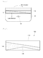
- FIG. 1 is a view illustrating a conventional passive anti-rolling tank.
- a passive anti-rolling tank 10 is formed in a hull 20 of a floating structure in such a way as to be left-right symmetrical in the port and starboard directions. Also, the passive anti-rolling tank 10 defines a closed space which accommodates fluid 15, and the fluid 15 is stored to have a free surface.
- the passive anti-rolling tank 10 is disposed in a shape which is left-right symmetrical with respect to a center of rotation 30 of the hull 20. Further, although the passive anti-rolling tank 10 may be positioned above the center of rotation 30 of the hull 20, as shown in the drawing, it is to be noted that the position of the passive anti-rolling tank 10 is not limited to this position, and may be changed according to the shape of the hull 20, and so on.
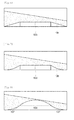
- FIG. 2 is a view illustrating a passive anti-rolling tank in accordance with a first embodiment of the present disclosure.
- a passive anti-rolling tank 100 in accordance with a first embodiment includes a tank body 110 which provides a closed space for accommodating free-surface fluid 150, and a protruding bottom wall 130 which is formed into a shape which protrudes from the bottom of the tank body 110 such that a larger amount of the fluid 150 is accommodated in the side portions rather than in the center portion of the tank body 110.
- the protruding bottom wall 130 may be fabricated separately from the tank body 110 and be attached to the bottom of the tank body 110, or may be fabricated integrally with the bottom of the tank body 110.
- the tank body 110 provides the closed space which accommodates the fluid 150.
- the fluid 150 is stored in the tank body 110 to have a free surface, and induces a moment according to rolling.
- the passive anti-rolling tank 100 plays the role of reducing the rolling of a hull, attributable to the phase difference between the rolling moment of the tank body 110 and the moment of the fluid 150 accommodated in the tank body 110 that is induced by the free-surface movement of the fluid 150.
- the embodiment of the present disclosure is to change the shape of the passive anti-rolling tank 100 and thereby induce a larger moment with a smaller amount of the fluid 150.
- the embodiment of the present disclosure is to provide the shape of the protruding bottom wall 130 which allows the load acting point of the fluid 150 to move outward.
- the protruding bottom wall 130 has a left-right symmetrical shape. This is to achieve a uniform anti-rolling effect with respect to leftward and rightward rolling.
- the protruding bottom wall 130 may be formed in such a manner that the depth of the fluid 150 at the center portion of the tank body 110 is less than the depth of the fluid 150 at the side portions of the tank body 110 in the state in which the tank body 110 is oriented horizontally. That is to say, the protruding bottom wall 130 may have a shape such that its center portion protrudes upward.
- FIG. 2 shows that the protruding bottom wall 130 is formed to have inclined surfaces which are inclined downward from the center portion to the side portions.
- the amounts of the fluid 150 which is stored in the center portion and the side portions are different from each other, attributable to the shape of the protruding bottom wall 130.
- an anti-rolling effect may be achieved using a smaller amount of the fluid 150.
- FIG. 3 is a view illustrating a passive anti-rolling tank in accordance with a second embodiment of the present disclosure
- FIG. 4 is a view illustrating a passive anti-rolling tank in accordance with a third embodiment of the present disclosure.
- the second embodiment of FIG. 3 shows that a protruding bottom wall 131 is formed into a convex curved surface shape
- the third embodiment of FIG. 4 shows that a protruding bottom wall 132 is formed to have concave curved surface shapes.
- FIG. 5 is a view illustrating a passive anti-rolling tank in accordance with a fourth embodiment of the present disclosure.
- the fourth embodiment of FIG. 5 shows that a planar protruding wall 133 is formed on the center portion of the bottom of a tank body. Attributable to the fact that the planar protruding wall 133 is formed on the center portion of the bottom of the tank body, an amount of fluid which may be stored in the center portion may be decreased, and thus, an effect that the load acting point of the fluid moves outward may be achieved.
- FIG. 6 is a view illustrating a passive anti-rolling tank in accordance with a fifth embodiment of the present disclosure
- FIG. 7 is a view illustrating a passive anti-rolling tank in accordance with a sixth embodiment of the present disclosure.
- the fifth embodiment of FIG. 6 shows that a protruding bottom wall is formed in a shape in which inclined walls 134 are connected to both sides of a planar protruding wall 133
- the sixth embodiment of FIG. 7 shows that a protruding bottom wall is formed in a shape in which curved walls 135 are connected to both sides of a planar protruding wall 133.
- FIG. 8 is a view illustrating a passive anti-rolling tank in accordance with a seventh embodiment of the present disclosure.
- the seventh embodiment shows that a protruding bottom wall is formed to have a convex curved surface shape 136 in the center portion thereof and concave curved surface shapes 137 on both sides of the convex curved surface shape 136.
- an amount of fluid necessary to achieve a predetermined level of anti-rolling effect may be reduced, whereby the overall weight may be decreased.
Landscapes
- Chemical & Material Sciences (AREA)
- Engineering & Computer Science (AREA)
- Combustion & Propulsion (AREA)
- Mechanical Engineering (AREA)
- Ocean & Marine Engineering (AREA)
- Filling Or Discharging Of Gas Storage Vessels (AREA)
- Sewage (AREA)
- Treatment Of Water By Ion Exchange (AREA)
- Rolling Contact Bearings (AREA)
Applications Claiming Priority (1)
| Application Number | Priority Date | Filing Date | Title |
|---|---|---|---|
| KR20130123322A KR20150044215A (ko) | 2013-10-16 | 2013-10-16 | 자유수면형 횡동요 감소 탱크 |
Publications (2)
| Publication Number | Publication Date |
|---|---|
| EP2886441A2 true EP2886441A2 (de) | 2015-06-24 |
| EP2886441A3 EP2886441A3 (de) | 2015-07-29 |
Family
ID=51726417
Family Applications (1)
| Application Number | Title | Priority Date | Filing Date |
|---|---|---|---|
| EP14189059.0A Withdrawn EP2886441A3 (de) | 2013-10-16 | 2014-10-15 | Passiver Schlingertank |
Country Status (4)
| Country | Link |
|---|---|
| EP (1) | EP2886441A3 (de) |
| JP (1) | JP2015077967A (de) |
| KR (1) | KR20150044215A (de) |
| CN (1) | CN104554646A (de) |
Families Citing this family (2)
| Publication number | Priority date | Publication date | Assignee | Title |
|---|---|---|---|---|
| CN105059494B (zh) * | 2015-08-24 | 2019-01-04 | 河北工程大学 | 一种设有舷门的减摇水舱及其减摇方法 |
| CN120573223B (zh) * | 2025-08-06 | 2025-10-10 | 招商局工业集团威海船舶有限公司 | 一种基于模型预测控制的船舶自适应减摇系统及方法 |
Citations (1)
| Publication number | Priority date | Publication date | Assignee | Title |
|---|---|---|---|---|
| KR20110101870A (ko) | 2010-03-10 | 2011-09-16 | 삼성중공업 주식회사 | 횡동요 저감형 선박 및 선박의 횡동요 제어 방법 |
Family Cites Families (10)
| Publication number | Priority date | Publication date | Assignee | Title |
|---|---|---|---|---|
| DE675003C (de) * | 1937-05-13 | 1939-04-27 | Askania Werke Akt Ges | Fluessigkeitstank fuer Wasserfahrzeuge zur Beeinflussung des Stabilitaetsmomentes |
| DE1287466B (de) * | 1964-07-30 | 1969-01-16 | ||
| US3272170A (en) * | 1964-10-27 | 1966-09-13 | Mcmullen Ass John J | Ship stabilizer using elongated weir means |
| GB1180401A (en) * | 1966-04-06 | 1970-02-04 | Mini Of Technology | Roll Stabilizer for Floating Bodies |
| GB1264787A (de) * | 1968-02-28 | 1972-02-23 | ||
| NO333766B1 (no) * | 2007-12-07 | 2013-09-16 | Marine Roll & Pitch Control As | System og fremgangsmate for aktiv og passiv stabilisering av fartoy |
| GR20090100402A (el) * | 2009-07-20 | 2011-02-18 | Ν. Τριανταφυλλης & Σια Ο.Ε., | Αυτοφερομενο οικολογικο συστημα δυναμικης αντισταθμισης θεσης πλευσης πλωτου μεσου δια μεταβολης της συνολικης υδροδυναμικης ροης κυτους |
| CN102574567B (zh) * | 2009-11-24 | 2014-12-31 | 三星重工业株式会社 | 减横摇型船舶 |
| CN202541800U (zh) * | 2012-04-06 | 2012-11-21 | 扬帆集团股份有限公司 | 一种用压载泵的自动防横倾系统 |
| CN202953147U (zh) * | 2012-11-20 | 2013-05-29 | 无锡美特船舶设备有限公司 | 分体式开型可控减摇水舱结构 |
-
2013
- 2013-10-16 KR KR20130123322A patent/KR20150044215A/ko not_active Withdrawn
-
2014
- 2014-10-15 EP EP14189059.0A patent/EP2886441A3/de not_active Withdrawn
- 2014-10-16 CN CN201410549430.9A patent/CN104554646A/zh active Pending
- 2014-10-16 JP JP2014211665A patent/JP2015077967A/ja active Pending
Patent Citations (1)
| Publication number | Priority date | Publication date | Assignee | Title |
|---|---|---|---|---|
| KR20110101870A (ko) | 2010-03-10 | 2011-09-16 | 삼성중공업 주식회사 | 횡동요 저감형 선박 및 선박의 횡동요 제어 방법 |
Also Published As
| Publication number | Publication date |
|---|---|
| CN104554646A (zh) | 2015-04-29 |
| JP2015077967A (ja) | 2015-04-23 |
| EP2886441A3 (de) | 2015-07-29 |
| KR20150044215A (ko) | 2015-04-24 |
Similar Documents
| Publication | Publication Date | Title |
|---|---|---|
| EP3228531B1 (de) | Meeresstrukturplattform mit bewegungsdämpfungsfunktion und tauchfähige meeresstruktur damit | |
| JP2016130077A5 (de) | ||
| EP2886441A2 (de) | Passiver Schlingertank | |
| CN107848601A (zh) | 船舶 | |
| KR20150076746A (ko) | 슬로싱 하중 저감 장치 | |
| Vlachos et al. | Modeling and control of a novel over-actuated marine floating platform | |
| WO2018070239A1 (ja) | 液化ガス運搬船 | |
| Xinhua et al. | Catastrophe characteristics and control of pitching supercavitating vehicles at fixed depths | |
| KR20130119071A (ko) | 선박의 핀 스태빌라이저 | |
| Korobkin et al. | Water-exit problem with prescribed motion of a symmetric body | |
| Ikezoe et al. | Experimental study on seakeeping performance of a catamaran with asymmetric demi-hulls | |
| KR102388163B1 (ko) | 선박 | |
| KR102393443B1 (ko) | 해상 부체 구조물 | |
| KR102535242B1 (ko) | 선미정류구조 및 선박 | |
| Crossland | Hydrodynamic Control of a Submarine Close to the Sea Surface | |
| Zhang et al. | On hydrodynamic behavior of a cylindrical moonpool with an entrapped two-layer fluid | |
| KR20130003500A (ko) | 횡동요 저감 탱크 및 이를 가지는 해상 구조물 | |
| KR101847015B1 (ko) | 하중 지지수단을 갖는 횡동요 저감 탱크 및 이를 가지는 해상 구조물 | |
| KR20150033487A (ko) | 개량형 폰툰 | |
| Holzgrafe | Transverse stability problems of small autonomous sailing vessels | |
| KR200469829Y1 (ko) | 선박용 방향타 | |
| Lin | Hydroelasticity analysis in frequency domain and time domain | |
| KR20170000073U (ko) | 컨테이너 선박 | |
| KR101259081B1 (ko) | 벌브를 구비한 선박 | |
| JP3196988U (ja) | 非突出バルブ船首船 |
Legal Events
| Date | Code | Title | Description |
|---|---|---|---|
| PUAI | Public reference made under article 153(3) epc to a published international application that has entered the european phase |
Free format text: ORIGINAL CODE: 0009012 |
|
| 17P | Request for examination filed |
Effective date: 20141015 |
|
| AK | Designated contracting states |
Kind code of ref document: A2 Designated state(s): AL AT BE BG CH CY CZ DE DK EE ES FI FR GB GR HR HU IE IS IT LI LT LU LV MC MK MT NL NO PL PT RO RS SE SI SK SM TR |
|
| AX | Request for extension of the european patent |
Extension state: BA ME |
|
| PUAL | Search report despatched |
Free format text: ORIGINAL CODE: 0009013 |
|
| AK | Designated contracting states |
Kind code of ref document: A3 Designated state(s): AL AT BE BG CH CY CZ DE DK EE ES FI FR GB GR HR HU IE IS IT LI LT LU LV MC MK MT NL NO PL PT RO RS SE SI SK SM TR |
|
| AX | Request for extension of the european patent |
Extension state: BA ME |
|
| RIC1 | Information provided on ipc code assigned before grant |
Ipc: B63B 43/06 20060101ALI20150619BHEP Ipc: B63B 39/03 20060101AFI20150619BHEP |
|
| STAA | Information on the status of an ep patent application or granted ep patent |
Free format text: STATUS: THE APPLICATION IS DEEMED TO BE WITHDRAWN |
|
| 18D | Application deemed to be withdrawn |
Effective date: 20160130 |