EP2886439A1 - Ballast-water treatment device and ballast-water management system - Google Patents
Ballast-water treatment device and ballast-water management system Download PDFInfo
- Publication number
- EP2886439A1 EP2886439A1 EP14801574.6A EP14801574A EP2886439A1 EP 2886439 A1 EP2886439 A1 EP 2886439A1 EP 14801574 A EP14801574 A EP 14801574A EP 2886439 A1 EP2886439 A1 EP 2886439A1
- Authority
- EP
- European Patent Office
- Prior art keywords
- ballast water
- ballast
- control device
- treatment apparatus
- water
- Prior art date
- Legal status (The legal status is an assumption and is not a legal conclusion. Google has not performed a legal analysis and makes no representation as to the accuracy of the status listed.)
- Ceased
Links
- XLYOFNOQVPJJNP-UHFFFAOYSA-N water Substances O XLYOFNOQVPJJNP-UHFFFAOYSA-N 0.000 title claims description 525
- 239000013535 sea water Substances 0.000 claims description 104
- 238000000034 method Methods 0.000 claims description 100
- 230000008569 process Effects 0.000 claims description 95
- 238000001914 filtration Methods 0.000 claims description 71
- 238000007599 discharging Methods 0.000 claims description 14
- 238000004140 cleaning Methods 0.000 description 49
- 238000010586 diagram Methods 0.000 description 30
- 238000012545 processing Methods 0.000 description 22
- 230000000694 effects Effects 0.000 description 18
- 239000000126 substance Substances 0.000 description 18
- 238000002360 preparation method Methods 0.000 description 17
- 238000000746 purification Methods 0.000 description 12
- 230000007423 decrease Effects 0.000 description 9
- 230000004397 blinking Effects 0.000 description 5
- -1 polyethylene Polymers 0.000 description 4
- 238000005086 pumping Methods 0.000 description 4
- 241000894006 Bacteria Species 0.000 description 2
- 239000002033 PVDF binder Substances 0.000 description 2
- 238000001816 cooling Methods 0.000 description 2
- 230000005611 electricity Effects 0.000 description 2
- 239000004744 fabric Substances 0.000 description 2
- 238000009434 installation Methods 0.000 description 2
- 238000013021 overheating Methods 0.000 description 2
- 229920000728 polyester Polymers 0.000 description 2
- 229920001343 polytetrafluoroethylene Polymers 0.000 description 2
- 239000004810 polytetrafluoroethylene Substances 0.000 description 2
- 229920002981 polyvinylidene fluoride Polymers 0.000 description 2
- 230000009467 reduction Effects 0.000 description 2
- 239000011347 resin Substances 0.000 description 2
- 229920005989 resin Polymers 0.000 description 2
- 230000004044 response Effects 0.000 description 2
- 239000004677 Nylon Substances 0.000 description 1
- 239000004698 Polyethylene Substances 0.000 description 1
- 239000004743 Polypropylene Substances 0.000 description 1
- 238000004891 communication Methods 0.000 description 1
- 238000011086 high cleaning Methods 0.000 description 1
- 230000002779 inactivation Effects 0.000 description 1
- 239000000463 material Substances 0.000 description 1
- 239000012528 membrane Substances 0.000 description 1
- 238000012986 modification Methods 0.000 description 1
- 230000004048 modification Effects 0.000 description 1
- 238000012544 monitoring process Methods 0.000 description 1
- 238000006386 neutralization reaction Methods 0.000 description 1
- 230000003472 neutralizing effect Effects 0.000 description 1
- 229920001778 nylon Polymers 0.000 description 1
- 239000012466 permeate Substances 0.000 description 1
- 238000005191 phase separation Methods 0.000 description 1
- 229920000573 polyethylene Polymers 0.000 description 1
- 229920000139 polyethylene terephthalate Polymers 0.000 description 1
- 239000005020 polyethylene terephthalate Substances 0.000 description 1
- 229920001155 polypropylene Polymers 0.000 description 1
- 229920002635 polyurethane Polymers 0.000 description 1
- 239000004814 polyurethane Substances 0.000 description 1
- 239000002244 precipitate Substances 0.000 description 1
- 238000009877 rendering Methods 0.000 description 1
- 239000008399 tap water Substances 0.000 description 1
- 235000020679 tap water Nutrition 0.000 description 1
Images












Classifications
-
- C—CHEMISTRY; METALLURGY
- C02—TREATMENT OF WATER, WASTE WATER, SEWAGE, OR SLUDGE
- C02F—TREATMENT OF WATER, WASTE WATER, SEWAGE, OR SLUDGE
- C02F1/00—Treatment of water, waste water, or sewage
- C02F1/30—Treatment of water, waste water, or sewage by irradiation
- C02F1/32—Treatment of water, waste water, or sewage by irradiation with ultraviolet light
- C02F1/325—Irradiation devices or lamp constructions
-
- B—PERFORMING OPERATIONS; TRANSPORTING
- B63—SHIPS OR OTHER WATERBORNE VESSELS; RELATED EQUIPMENT
- B63J—AUXILIARIES ON VESSELS
- B63J4/00—Arrangements of installations for treating ballast water, waste water, sewage, sludge, or refuse, or for preventing environmental pollution not otherwise provided for
- B63J4/002—Arrangements of installations for treating ballast water, waste water, sewage, sludge, or refuse, or for preventing environmental pollution not otherwise provided for for treating ballast water
-
- B—PERFORMING OPERATIONS; TRANSPORTING
- B63—SHIPS OR OTHER WATERBORNE VESSELS; RELATED EQUIPMENT
- B63B—SHIPS OR OTHER WATERBORNE VESSELS; EQUIPMENT FOR SHIPPING
- B63B13/00—Conduits for emptying or ballasting; Self-bailing equipment; Scuppers
-
- C—CHEMISTRY; METALLURGY
- C02—TREATMENT OF WATER, WASTE WATER, SEWAGE, OR SLUDGE
- C02F—TREATMENT OF WATER, WASTE WATER, SEWAGE, OR SLUDGE
- C02F1/00—Treatment of water, waste water, or sewage
- C02F1/001—Processes for the treatment of water whereby the filtration technique is of importance
-
- C—CHEMISTRY; METALLURGY
- C02—TREATMENT OF WATER, WASTE WATER, SEWAGE, OR SLUDGE
- C02F—TREATMENT OF WATER, WASTE WATER, SEWAGE, OR SLUDGE
- C02F2103/00—Nature of the water, waste water, sewage or sludge to be treated
- C02F2103/008—Originating from marine vessels, ships and boats, e.g. bilge water or ballast water
-
- C—CHEMISTRY; METALLURGY
- C02—TREATMENT OF WATER, WASTE WATER, SEWAGE, OR SLUDGE
- C02F—TREATMENT OF WATER, WASTE WATER, SEWAGE, OR SLUDGE
- C02F2201/00—Apparatus for treatment of water, waste water or sewage
- C02F2201/32—Details relating to UV-irradiation devices
- C02F2201/322—Lamp arrangement
- C02F2201/3227—Units with two or more lamps
-
- C—CHEMISTRY; METALLURGY
- C02—TREATMENT OF WATER, WASTE WATER, SEWAGE, OR SLUDGE
- C02F—TREATMENT OF WATER, WASTE WATER, SEWAGE, OR SLUDGE
- C02F2201/00—Apparatus for treatment of water, waste water or sewage
- C02F2201/32—Details relating to UV-irradiation devices
- C02F2201/328—Having flow diverters (baffles)
-
- C—CHEMISTRY; METALLURGY
- C02—TREATMENT OF WATER, WASTE WATER, SEWAGE, OR SLUDGE
- C02F—TREATMENT OF WATER, WASTE WATER, SEWAGE, OR SLUDGE
- C02F2209/00—Controlling or monitoring parameters in water treatment
- C02F2209/005—Processes using a programmable logic controller [PLC]
-
- C—CHEMISTRY; METALLURGY
- C02—TREATMENT OF WATER, WASTE WATER, SEWAGE, OR SLUDGE
- C02F—TREATMENT OF WATER, WASTE WATER, SEWAGE, OR SLUDGE
- C02F2209/00—Controlling or monitoring parameters in water treatment
- C02F2209/40—Liquid flow rate
-
- C—CHEMISTRY; METALLURGY
- C02—TREATMENT OF WATER, WASTE WATER, SEWAGE, OR SLUDGE
- C02F—TREATMENT OF WATER, WASTE WATER, SEWAGE, OR SLUDGE
- C02F2301/00—General aspects of water treatment
- C02F2301/04—Flow arrangements
- C02F2301/043—Treatment of partial or bypass streams
-
- C—CHEMISTRY; METALLURGY
- C02—TREATMENT OF WATER, WASTE WATER, SEWAGE, OR SLUDGE
- C02F—TREATMENT OF WATER, WASTE WATER, SEWAGE, OR SLUDGE
- C02F2303/00—Specific treatment goals
- C02F2303/04—Disinfection
Definitions
- the present invention relates to an apparatus for treating ballast water stored in a ship and a ballast water management system including an apparatus for treating ballast water.
- Ballast water is seawater carried in a ship to provide safe voyage in the sea when the ship carries no cargo. Ballast water is taken up from a seawater environment around a ship at a departure port of the ship and loaded into the ship. The ballast water is discharged around the ship at a destination port of the ship.
- ballast water is discharged into a seawater environment different from a seawater environment where the ballast water is taken up.
- Organisms in the ballast water are transported to a seawater environment different from their original habitat, resulting in a problem in that the organisms in the ballast water affect the ecosystem in the seawater environment into which the ballast water is discharged.
- Japanese Unexamined Patent Application Publication No. 2013-23187 discloses a ballast water treatment apparatus for the purpose of reliably and efficiently conducting a treatment for rendering ballast water harmless.
- This treatment apparatus includes a filter and an ultraviolet irradiation unit. Untreated water introduced into a ballast water treatment line is first allowed to pass through the filter. Next, the untreated water passes through the ultraviolet irradiation unit. While the untreated water passes through the ultraviolet irradiation unit, the untreated water is irradiated with ultraviolet light. Consequently, the untreated water is sterilized.
- the above apparatus is provided in order to solve a problem in that the amount of ultraviolet irradiation is insufficient in a state where untreated water has a very high turbidity.
- the treatment apparatus disclosed in the above document discharges pumped untreated water around a ship without allowing the untreated water to pass through the ultraviolet irradiation unit until the illuminance of an ultraviolet lamp reaches a predetermined value. When the illuminance of the ultraviolet lamp reaches the predetermined value, the pumped untreated water is allowed to pass through the ultraviolet irradiation unit and poured into a ballast tank.
- ballast water is irradiated with ultraviolet light in order to kill microbes.
- ballast water may be stored in a ballast tank while microbes in the ballast water are not completely killed. Accordingly, the ballast water discharged into the sea may affect the ecosystem in a seawater environment. A technique for more reliably reducing the possibility that ballast water will affect the ecosystem in a seawater environment has been desired.
- An object of the present invention is to provide a technique for more reliably reducing the possibility that ballast water will affect the ecosystem in a seawater environment.
- a ballast water treatment apparatus includes a discharge path for discharging ballast water from a ballast tank that stores the ballast water, an ultraviolet irradiation device that includes an ultraviolet lamp and that irradiates the ballast water passing through the discharge path with ultraviolet light, a circulation path formed so that the ballast water circulates therethrough and is irradiated with ultraviolet light emitted from the ultraviolet lamp, a switching portion for switching a path through which the ballast water flows between the circulation path and the discharge path, and a control device that controls the switching portion so that the ballast water flows through the circulation path during a switching-on process of the ultraviolet lamp and controls the switching portion so that the ballast water flows through the discharge path when the switching on of the ultraviolet lamp is completed.
- the ballast water when the ballast water is discharged from the ballast tank through the discharge path, the ballast water is irradiated with ultraviolet light emitted from the ultraviolet irradiation device. Consequently, microbes in the ballast water can be killed. Since a purification treatment of ballast water can be performed immediately before the discharge of the ballast water, the possibility of an effect on the ecosystem in a seawater environment can be more reliably reduced. Furthermore, during the switching-on process of the ultraviolet lamp, the ballast water passes through the circulation path and thus is not discharged from the ballast water treatment apparatus.
- ballast water is irradiated with ultraviolet light and discharged from the ballast water treatment apparatus.
- the effect of killing microbes contained in ballast water can be enhanced.
- the circulation path and the discharge path may be partially common to each other or may each be independently arranged.
- a ballast water management system includes the above ballast water treatment apparatus, a ballast tank that stores the ballast water, and a pump that pumps the ballast water from the ballast tank and sends the ballast water to the discharge path.
- ballast pump 1 ballast pump, 2 filtering device, 2A reverse cleaning device, 3 ultraviolet irradiation device, 4 drainage pump, 5 ballast tank, 10 to 27 line, 27 pressurizing pipe, 31 to 36, 40 to 44 valve, 51, 52, 53, 54 flow meter, 61 filter, 62 untreated water nozzle, 63, 141 case, 64 filtered water flow path, 65 discharge flow path, 66 untreated water flow path, 67 nozzle opening, 68 cleaning water tank, 70 chemical inlet, 71 outer cylindrical portion, 72 lid portion, 73 bottom portion, 80 central pipe, 81 intake hole, 90 motor, 91 motor cover, 100 ballast water management system, 101 ballast water treatment apparatus, 102 bypass system, 111, 112 control device, 121, 131 display panel, 122 bypass lamp, 123 BWMS enable lamp, 124, 132 operation mode switch, 125 processing mode switch, 126, 133 BWMS preparation lamp, 127 BWMS start button, 128 BWMS stop button, 129, 135 emergency stop button
- a ballast water treatment apparatus includes a discharge path for discharging ballast water from a ballast tank that stores the ballast water, an ultraviolet irradiation device that includes an ultraviolet lamp and that irradiates the ballast water passing through the discharge path with ultraviolet light, a circulation path formed so that the ballast water circulates therethrough and is irradiated with ultraviolet light emitted from the ultraviolet lamp, a switching portion for switching a path through which the ballast water flows between the circulation path and the discharge path, and a control device that controls the switching portion so that the ballast water flows through the circulation path during a switching-on process of the ultraviolet lamp and controls the switching portion so that the ballast water flows through the discharge path when the switching on of the ultraviolet lamp is completed.
- the ballast water when the ballast water is discharged from the ballast tank through the discharge path, the ballast water is irradiated with ultraviolet light emitted from the ultraviolet irradiation device. Consequently, microbes in the ballast water can be killed. Since a purification treatment of ballast water can be performed immediately before the discharge of the ballast water, the possibility of an effect on the ecosystem in a seawater environment can be more reliably reduced. Furthermore, during the switching-on process of the ultraviolet lamp, the ballast water passes through the circulation path and thus is not discharged from the ballast water treatment apparatus.
- ballast water is irradiated with ultraviolet light and discharged from the ballast water treatment apparatus.
- the effect of killing microbes contained in ballast water can be enhanced.
- the circulation path and the discharge path may be partially common to each other or may each be independently arranged.
- the control device in the switching-on process of the ultraviolet lamp, when an electric power supplied to the ultraviolet lamp reaches a maximum electric power for the ultraviolet lamp, the control device permits the switching portion to switch from the circulation path to the discharge path.
- the ultraviolet irradiation process it is possible to reduce the time required until the ultraviolet irradiation process can be performed. For example, immediately after starting pumping of ballast water from the ballast tank, turbidity of the ballast water may increase temporarily.
- the electric power supplied to the ultraviolet lamp By setting the electric power supplied to the ultraviolet lamp to the maximum electric power for the ultraviolet lamp, the amount of irradiation of ultraviolet light applied to the ballast water can be increased. Accordingly, the ultraviolet irradiation process can be started within a short time from the start of the switching on of the ultraviolet lamp.
- the ultraviolet lamp is provided in a path common to the discharge path and the circulation path.
- the control device switches off the ultraviolet lamp and switches the path of the ballast water from the discharge path to the circulation path.
- the ultraviolet lamp after the ultraviolet lamp is switched off, the ultraviolet lamp can be cooled by seawater passing through the ultraviolet irradiation device.
- the ballast water treatment apparatus further includes a filtering device that filters the ballast water and that supplies the filtered ballast water to the ultraviolet irradiation device when the ballast water is stored in the ballast tank.
- the circulation path and the discharge path include a common path that bypasses the filtering device.
- ballast water filtered by the filtering device is stored in the ballast tank. Consequently, while the ballast water is discharged from the ballast tank, filtration by the filtering device can be made unnecessary by allowing the ballast water to pass through the path which bypasses the filtering device. Accordingly, the process during discharge of the ballast water can be simplified.
- a ballast water management system includes the above ballast water treatment apparatus, a ballast tank that stores the ballast water, and a pump that pumps the ballast water from the ballast tank and sends the ballast water to the discharge path.
- the ballast water management system further includes a bypass system for feeding seawater into the ballast tank and discharging seawater from the ballast tank while bypassing the ballast water treatment apparatus.
- seawater can be fed into or discharged from the ballast tank.
- ballast water refers to seawater stored in a ballast tank. Accordingly, in this specification, in the case where ballast water is seawater, an expression “ballast water (seawater)” may be used.
- the term “untreated water” refers to seawater that is treated by a ballast water treatment apparatus according to the present embodiment.
- the term “untreated water” covers not only seawater taken up from a seawater environment to the ballast water treatment apparatus but also "ballast water”.
- the term “ballast water” and the term “untreated water” are not necessarily distinguished from each other, the term “seawater” may be used.
- FIG. 1 is an overall diagram of a ballast water management system according to an embodiment of the present invention.
- a ballast water management system 100 according to an embodiment of the present invention is installed in a ship (not shown).
- the ballast water management system 100 takes up seawater from a seawater environment around the ship and stores the seawater as ballast water in a ballast tank 5.
- the ballast water management system 100 discharges the ballast water stored in the ballast tank 5 into a seawater environment around the ship.
- the ballast tank 5 may be separated into a plurality of sections.
- the ballast water management system 100 includes a ballast water treatment apparatus 101, a bypass system 102, and control devices 111 and 112.
- the ballast water treatment apparatus 101 and the bypass system 102 are main components of the ballast water management system 100 and can be constituted as a ballast water management apparatus.
- the ballast water treatment apparatus 101 While taking up seawater from a seawater environment around the ship, the ballast water treatment apparatus 101 performs a purification treatment of the seawater. Furthermore, while discharging ballast water (seawater) from the ballast tank 5, the ballast water treatment apparatus 101 can perform a purification treatment of the ballast water stored in the ballast tank.
- the term "purification” covers removal, killing, and inactivation of microbes contained in seawater.
- the bypass system 102 can load the uptaken seawater into the ballast tank 5 while the seawater bypasses the ballast water treatment apparatus 101. Furthermore, while ballast water (seawater) is discharged from the ballast tank 5, the bypass system 102 can discharge the ballast water into the sea while the ballast water bypasses the ballast water treatment apparatus 101. Specifically, the bypass system 102 forms a path for feeding ballast water into the ballast tank 5 and discharging the ballast water from the ballast tank 5 while the ballast water bypasses the ballast water treatment apparatus 101.
- seawater can be fed into or discharged from the ballast tank 5 through the bypass system 102.
- ballast water treatment apparatus 101 and the bypass system 102 share some of components.
- the ballast water management system 100 according to an embodiment of the present invention can be realized by adding the ballast water treatment apparatus 101. Accordingly, the ballast water management system 100 according to an embodiment of the present invention can be installed in the ship without significantly changing existing facilities.
- the ballast water treatment apparatus 101 includes a ballast pump 1, a filtering device 2, an ultraviolet irradiation device 3, a drainage pump 4, lines 10 to 22 for passing seawater, valves 31 to 36, 40, 41, and 44, and flow meters 51, 52, and 53. Each of the lines is realized by arranging a pipe.
- the line 10 is a line for taking seawater from a seawater environment.
- the line 11 is a line for passing the seawater that flows into the ballast pump 1.
- the line 12 is a line for passing the seawater that flows from the ballast pump 1.
- the ballast pump 1 suctions seawater from the lines 10 and 11 and discharges the seawater to the line 12.
- the line 12 is branched into the line 13 and the line 14.
- the line 13 is a line for introducing the seawater into the filtering device 2.
- the line 14 forms a path that joins to the line 15 while bypassing the filtering device 2.
- the valve 32 controls a flow rate of the seawater flowing through the line 13.
- the valve 33 controls a flow rate of the seawater flowing through the line 14.
- the filtering device 2 filters seawater that flows in the filtering device 2 through the line 13.
- the filtered seawater flows from the filtering device 2 through the line 15.
- the line 15 guides the seawater filtered by the filtering device 2 to the ultraviolet irradiation device 3. That is, the line 15 forms a path for supplying the seawater filtered by the filtering device 2 to the ultraviolet irradiation device 3.
- the flow meter 52 measures a flow rate of the seawater flowing through the line 15.
- seawater that has not been filtered by the filtering device 2 is discharged from the filtering device 2 through the line 16.
- the line 17 is branched from the line 16.
- the lines 16 to 18 form a discharge water path for discharging seawater remaining in the filtering device 2.
- the line 17 is a line for discharging the seawater that flows from the line 16 to the sea.
- the valve 35 is provided in the line 17 and controls a flow rate of the seawater flowing through the line 17.
- the line 16 is connected to an inlet of the drainage pump 4.
- the line 18 is a line for passing the seawater that flows from the drainage pump 4.
- the line 18 joins to the line 17.
- the seawater discharged from the drainage pump 4 flows through the line 18 and is discharged into the sea.
- the valve 36 is provided in the line 18 and controls a flow rate of the seawater flowing through the line 18.
- the flow meter 53 measures a flow rate of the seawater flowing through the line 18.
- the drainage pump 4 is smaller than the ballast pump 1. Specifically, a discharge capacity of the drainage pump 4 is lower than the discharge capacity of the ballast pump 1. By using a small pump as the drainage pump 4, a reduction in the size of the ballast water treatment apparatus 101 can be realized.
- the ultraviolet irradiation device 3 includes an ultraviolet (UV) lamp (not shown).
- the seawater flowing through the line 15 is passed through the ultraviolet irradiation device 3.
- the seawater passing through the ultraviolet irradiation device 3 is irradiated with ultraviolet light emitted from the ultraviolet lamp.
- Untreated water is filtered by a filter 61 (refer to Fig. 4 ) and then irradiated with ultraviolet light in the ultraviolet irradiation device 3. Accordingly, even when a small UV lamp is used, an effect of killing microbes inhabiting in the filtered seawater can be obtained.
- advantages such as a reduction in the size of the device and saving of power consumption can be obtained.
- the line 19 is a line for passing the seawater that flows from the ultraviolet irradiation device 3.
- the line 20 is a line for branching, from the line 19, the seawater that flows from the ultraviolet irradiation device 3 and guiding the seawater to the ballast tank 5.
- the line 21 is connected to the line 20 through the valve 40.
- the line 21 is a line for pouring the seawater to the ballast tank 5. That is, the lines 19, 20, and 21 form a path for supplying the untreated water flowing from the ultraviolet irradiation device 3 to the ballast tank 5.
- the line 21 also functions as a line for discharging seawater from the ballast tank 5.
- a flow meter 54 measures a flow rate of seawater flowing through the line 21.
- the line 22 is branched from the line 19 and forms a path for discharging the seawater that flows from the ultraviolet irradiation device 3 through the line 19 to the sea.
- the valve 41 is provided in the line 22 and controls a flow rate of the seawater flowing through the line 22.
- Each of the valves 31, 32, 33, 35, 36, 40, and 41 is, for example, a proportional control valve.
- the opening degree of each of the valves is controlled by a signal input to the valve.
- the valve 34 is, for example, an on-off valve.
- the valve 34 switches the state thereof between an open state and a closed state in accordance with a signal input to the valve 34.
- the valve 34 may be a proportional control valve.
- the bypass system 102 includes a ballast pump 1, lines 10 to 12 and 20 to 24, and valves 31, and 40 to 43. As in the ballast water treatment apparatus, each of the lines is realized by arranging a pipe.
- the ballast pump 1, the lines 10, 11, 12, 20, and 21, and the valves 31 and 40 are components common to the ballast water treatment apparatus 101 and the bypass system 102. Therefore, a detailed description of these components is not repeated below.
- the line 23 is connected to the line 21 through the valve 42.
- the valve 42 controls a flow rate of seawater flowing through the line 23.
- the line 24 is branched from the line 19 and connected to the line 12.
- the valve 43 is provided in the line 24 and controls a flow rate of seawater flowing through the line 24.
- Each of the valves 42 and 43 is, for example, a proportional control valve.
- the opening degree of each of the valves is changed in accordance with the magnitude of an input signal.
- the ballast water management system 100 further includes the control devices 111 and 112.
- the control devices 111 and 112 can be operated by an operator (not shown). An operation of a control device by an operator corresponds to an input of an instruction to the control device by the operator.
- the control devices 111 and 112 receive an instruction from an operator and control the ballast water management system 100 in accordance with the instruction. That is, the control devices 111 and 112 also function as setting devices for setting an operation mode of the ballast water management system. Specifically, the control devices 111 and 112 control driving and stopping of the ballast pump 1 and the drainage pump 4. Furthermore, the control devices 111 and 112 control the open/close or the opening degree of each of the valves shown in Fig. 1 . Furthermore, the control devices 111 and 112 control switching on and switching off of an UV lamp (not shown) included in the ultraviolet irradiation device 3.
- an UV lamp not shown
- the control devices 111 and 112 each have a communication function.
- the control device 111 can grasp its setting and transmit information relating to the setting to the control device 112.
- the control device 112 can grasp its setting and transmit information relating to the setting to the control device 111. Accordingly, the control device 111 and the control device 112 can be installed in separate places.
- control device 111 is installed near the ballast water treatment apparatus 101.
- control device 112 is installed in, for example, a bridge.
- an operator can perform remote control of the ballast water management apparatus (ballast water treatment apparatus 101 and the bypass system 102) by using the control device 112 in the bridge.
- the operator can control the operation and stop of the ballast water management system 100 by operating any one of the control devices 111 and 112. Furthermore, by operating any one of the control devices 111 and 112, the operator can switch the operation mode of the ballast water management system 100 between a ballast water treatment mode (referred to as "BWMS" (ballast water management system) mode in the present embodiment) and a bypass (“BYPASS”) mode.
- BWMS ballast water treatment mode
- BYPASS bypass
- the ballast water treatment mode is a mode in which the ballast water treatment apparatus 101 is operated.
- the bypass mode is a mode in which the bypass system 102 is operated while the ballast water treatment apparatus 101 is stopped.
- the operator can switch a processing mode by operating any one of the control devices 111 and 112.
- the processing mode includes a "Manual mode", a "Ballast mode", and a "De-Ballast mode”.
- the "Manual mode” is a mode in which an operator specifies a particular valve in operating any of the control devices 111 and 112, and specifies the open/close or the opening degree of the valve.
- the "Ballast mode” is a mode in which the ballast water management system 100 performs a process including taking up seawater from the sea, treating the seawater, and pouring the treated seawater into the ballast tank 5.
- the "De-Ballast mode” is a mode in which the ballast water management system 100 performs a process of discharging ballast water (seawater) stored in the ballast tank 5 to the sea. In the “Ballast mode” and the “De-Ballast mode", each of the valves is automatically controlled by the control device 111 or 112.
- control devices 111 and 112 are realized as control panels.
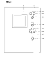
- Figure 2 is a schematic view showing a structural example of a control panel on the main body side of a ballast water treatment apparatus.
- a control device 111 (control panel) includes a display panel 121, a bypass lamp 122, a BWMS enable lamp 123, an operation mode switch 124, a processing mode switch 125, a BWMS preparation lamp 126, a BWMS start button 127, a BWMS stop button 128, and an emergency stop button 129.
- the display panel 121 displays, for example, an operation state of the ballast water management system 100.
- the display panel 121 has a function of a touch panel. With this structure, an operator can input various types of setting to the control device 111 by touching the display panel 121 (touch panel).
- the bypass lamp 122 is a lamp for indicating that the operation mode of the ballast water management system 100 is in the BYPASS mode.
- the bypass lamp 122 switches on.
- the bypass lamp 122 switches off.
- the BWMS enable lamp 123 is a lamp for indicating a state in which the ballast water treatment apparatus 101 can be used.
- the "state in which the ballast water treatment apparatus 101 can be used" refers to a state in which, in both the control device 111 and the control device 112, the operation mode of the ballast water management system 100 is set to the BWMS mode. In this case, the BWMS enable lamp 123 switches on.
- the ballast water treatment apparatus 101 is in a state in which the ballast water treatment apparatus 101 cannot be used.
- the BWMS enable lamp 123 blinks.
- the operation mode of the ballast water management system 100 is in the BYPASS mode
- the BWMS enable lamp 123 switches off.
- the BWMS enable lamp 123 varies its indication form through switched on, blinking, and switched off.
- the operation mode switch 124 is a switch used by the operator to notify the control device 111 of the operation mode of the ballast water treatment apparatus 101. Specifically, the operation mode switch 124 is configured so that the operation mode of the ballast water treatment apparatus 101 can be switched between the BYPASS mode and the BWMS mode.
- the processing mode switch 125 is a switch for instructing the processing mode of the ballast water treatment apparatus 101 to the control device 111 by the operator when the BWMS mode is selected. Specifically, the processing mode switch 125 is configured so that the processing mode of the ballast water treatment apparatus 101 can be switched among the "Manual mode", the "Ballast mode", and the "De-Ballast mode”.
- the BWMS preparation lamp 126 blinks during start-up of the ballast water treatment apparatus 101.
- the blinking rate of the BWMS preparation lamp 126 increases.
- the BWMS preparation lamp 126 becomes sufficiently bright so as to distinguish the state where the ballast water treatment apparatus 101 is under start-up from the state where the start-up of the ballast water treatment apparatus 101 is completed. Accordingly, the BWMS preparation lamp 126 may switch on during the start-up of the ballast water treatment apparatus 101, and the BWMS preparation lamp 126 may blink when the start-up of the ballast water treatment apparatus 101 is completed.
- the term “switched on” refers to a state in which light is continuously emitted.
- blinking refers to a state in which a light-emitting state and a non-light-emitting state are alternately repeated.
- the BWMS start button 127 is an operation bottom used by the operator to instruct the control device 111 to start a purification treatment of seawater using the ballast water treatment apparatus 101.
- the BWMS stop button 128 is an operation bottom used by the operator to instruct the control device 111 to stop the purification treatment of seawater using the ballast water treatment apparatus 101.
- the control device 111 receives an instruction of the start of the purification treatment of seawater.
- the control device 111 receives an instruction of the stop of the treatment of purifying seawater.
- the emergency stop button 129 is an operation button for stopping the operation of the ballast water treatment apparatus 101 in case of emergency.
- FIG. 3 is a schematic view showing a structural example of a control panel on the bridge side of a ship.
- the control device 112 (control panel) includes a display panel 131, an operation mode switch 132, a BWMS preparation lamp 133, and a start button 134, and an emergency stop button 135.
- the display panel 131 displays an operation state of the ballast water management system 100.
- the display panel 131 displays an operation mode set by an operator.
- the display panel 131 may have a function of a touch panel.
- the function possessed by the control device 111 shown in Fig. 2 can be realized by the display panel 131 (touch panel).
- the operator can select the processing mode and notify the control device 112 of the selected processing mode by touching the display panel 131 (touch panel).
- the display panel 131 can display the selected processing mode.
- the operation mode switch 132 is a switch used by the operator to notify the control device 112 of the operation mode of the ballast water treatment apparatus 101.
- the operation mode switch 132 is configured so that the operation mode of the ballast water treatment apparatus 101 can be switched between the BYPASS mode and the BWMS mode.
- the BWMS preparation lamp 133 performs the same operation as that of the BWMS preparation lamp 126 shown in Fig. 2 . Specifically, the BWMS preparation lamp 133 blinks during start-up of the ballast water treatment apparatus 101. When the start-up of the ballast water treatment apparatus 101 is completed, the blinking rate of the BWMS preparation lamp 133 increases.
- the start button 134 is an operation button used by the operator to notify the control device 112 of the operation of the ballast water management system 100 in a selected operation mode.
- the emergency stop button 135 is an operation button for stopping the operation of the ballast water treatment apparatus 101 in case of emergency.
- control device 111 and the control device 112 have different structures.
- the structures of the control devices 111 and 112 are not limited thereto.
- the control device 111 and the control device 112 may have the same structure.
- the display panels 121 and 131 are touch panels and can receive the operation of an operator.
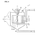
- Figure 4 is a view illustrating a structural example of the filtering device 2 shown in Fig. 1 .
- Figure 5 is a cross-sectional view taken along line V-V of Fig. 4 .
- seawater which is untreated water passes through a untreated water flow path 66 corresponding to the line 13 of Fig. 1 and is supplied to the inside of a case 63.
- a filter 61 having a cylindrical shape is provided in the case 63.
- An axis line C denotes a central axis of the filter 61 (cylinder). In other words, the filter 61 is arranged so as to surround the axis line C.
- a motor 90 is connected to the central axis of the filter 61.
- the motor 90 rotates the filter 61 around the axis line C as a center.
- the motor 90 is covered with a motor cover 91.
- the motor 90 is controlled by, for example, the control device 111.
- a rotatable attachment structure also needs to have a watertight structure.
- the structure is not particularly limited and a known structure may be used.
- the case 63 covers the whole of the filter 61.
- the case 63 includes an outer cylindrical portion 71, a lid portion 72, and a bottom portion 73.
- a discharge flow path 65 corresponding to the line 16 of Fig. 1 is provided in the bottom portion 73.
- the untreated water flow path 66 and an untreated water nozzle 62 are provided inside the case 63 in order to introduce seawater as the untreated water.
- a chemical inlet 70 is provided on the lid portion of the case 63. However, the chemical inlet need not necessarily be provided in the case 63.
- the untreated water nozzle 62 is provided so as to extend from the untreated water flow path 66.
- a nozzle opening 67 is formed at an end of the untreated water nozzle 62.
- the nozzle opening 67 is arranged in the outer cylindrical portion 71 of the case 63.
- the nozzle opening 67 is formed so that the untreated water flows out from the nozzle opening 67 toward an outer circumferential surface of the filter 61.
- a central pipe 80 is arranged on the axis line C.
- the central pipe 80 is connected to a filtered water flow path 64 corresponding to the line 15 of Fig. 1 . Note that the central pipe 80 does not rotate.
- FIG. 6 is a schematic perspective view illustrating a typical structure of the filter 61 shown in Fig. 4 .
- the filter 61 is a pleated filter.
- a so-called pleated shape is formed by folding a planar strip-shaped base so as to have alternating peaks and valleys.
- a cylindrical pleated filter is formed by connecting two ends of the pleated base to each other.
- a porous resin sheet is used as the base of the filter.
- the material of the porous resin sheet that can be used include porous structures such as a stretched porous body, a porous body by phase separation, and a non-woven cloth that are composed of polyester, nylon, polyethylene, polypropylene, polyurethane, polytetrafluoroethylene (PTFE), polyvinylidene fluoride (PVdF), or the like.
- a non-woven cloth composed of a polyester such as polyethylene terephthalate is particularly suitably used.
- untreated water passes through the untreated water flow path 66, and is ejected from the nozzle opening 67 of the untreated water nozzle 62.
- the untreated water ejected from the nozzle opening 67 is permeated from the outside of the cylinder of the filter 61 to the inside of the cylinder thereof. Accordingly, the untreated water is filtered.
- the untreated water filtered by permeating the filter 61 is guided to the filtered water flow path 64 through intake holes 81 provided in the central pipe 80, and allowed to flow to the outside of the filtering device 2.
- untreated water that has not been filtered by the filter 61 and suspensoid precipitated on the bottom portion 73 of the case 63 are discharged outside the filtering device 2 through the discharge flow path 65.
- the filtration is performed while the suspensoid or the remaining untreated water is continuously discharged in this manner.
- an amount of treatment for example, 10 to 20 ton/h, and furthermore, 100 ton/h which is required as an amount of treatment of ballast water can be ensured.
- suspensoid adheres to the outer circumferential surface of the filter 61.
- the motor 90 rotates the filter 61.
- the untreated water ejected from the nozzle opening 67 comes in contact with the outer circumferential surface of the rotating filter 61.
- a stream of water is constantly generated on the outer circumferential surface of the filter 61 by a pressure of the untreated water and a rotating stream of water.
- suspensoid adhering to the filter 61 is easily removed. That is, according to the present embodiment, in addition to the effect of filtering untreated water, a certain cleaning effect can also be obtained.
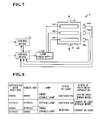
- FIG. 7 is a diagram showing a structural example of the ultraviolet irradiation device 3 shown in Fig. 1 .
- the ultraviolet irradiation device 3 includes a case 141, UV lamps 142, a lamp power supply 143, and illuminance sensors 144a, 144b, and 144c.
- the case 141 is arranged between the line 15 and line 19.
- the case 141 houses the UV lamps 142. Untreated water passes inside the ultraviolet irradiation device 3 through the lines 15 and 19.
- the untreated water passing through the inside of the case 141 is irradiated with ultraviolet light emitted from the UV lamps 142.
- switching on and switching off of the UV lamps 142 are controlled by the control device 111 or the control device 112.
- the illuminance sensors 144a to 144c each measure an illuminance of ultraviolet light emitted from the corresponding UV lamp 142 and transmitted through the untreated water.
- the illuminance detected by each of the illuminance sensors is transmitted from the illuminance sensors to the control device 111.
- the control device 111 instructs the lamp power supply 143 on a ratio relative to a maximum electric power of the UV lamps 142.
- the lamp power supply 143 supplies each of the UV lamps 142 with an electric power corresponding to the instructed ratio.
- an operator of the ballast water management system 100 can operate both the control device 111 and the control device 112. In the case where there is only a single device for setting (and monitoring) the ballast water management system 100, the operator must move to an installation place of the control device 111. In the case of a large structure such as a ship, the operator may need a large labor for moving to the installation place of the control device 111.
- the ballast water management system 100 includes a plurality of control devices used by an operator to set (and monitor) an operation mode of the ballast water management system 100.
- the plurality of control devices can be separately arranged in a ship. Accordingly, the operator can use a control device arranged near the operator. Thus, convenience of the operator can be enhanced.
- the setting of the operation mode may differ between the control device 111 and the control device 112 at a certain time. More specifically, there may be a case where the setting of the operation mode switch 124 shown in Fig. 2 and the setting of the operation mode switch 132 shown in Fig. 3 differs from each other.
- the ballast water management system 100 when the setting of an operation mode of the ballast water management system 100 in the control device 111 is the same as that in the control device 112, the ballast water management system 100 allows the operation in the operation mode.
- the ballast water management system 100 can operate in accordance with the set operation mode.
- the ballast water management system 100 allows neither the operation in the operation mode set in the control device 111 nor the operation in the operation mode set in the control device 112.
- the control device 111 determines allowance and prohibition of the operation of the ballast water management system 100. More specifically, the control device 111 checks the setting of the operation mode of the ballast water management system 100 in the control device 111. The control device 111 further acquires, from the control device 112, information relating to the setting of the operation mode of the ballast water management system 100 in the control device 112. When the setting in the control device 112 is the same as that in the control device 111, the control device 111 allows the ballast water management system 100 to operate in the operation mode.
- the ballast water management system 100 can be operated in a correct operation mode as a result of the control described above.
- the term "correct operation mode" refers to an operation mode intended by an operator. In other words, the above control can prevent the ballast water management system 100 from operating in an operation mode that is not intended by an operator.
- Another control is conceivable in the case where the setting of the operation mode differs between the control device 111 and the control device 112. For example, it is assumed that the setting in the control device 111 constantly takes precedence over the setting in the control device 112. That is, when the setting differs between the control device 111 and the control device 112, the setting in the control device 111 is constantly determined to be correct.
- an incorrect operation mode (that is not intended by the operator) is set to the ballast water management system 100.
- the ballast water management system 100 in the case where the setting of the operation mode in the control device 111 is the same as that in the control device 112, the ballast water management system 100 can operate in the operation mode. Accordingly, the operation of the ballast water management system 100 in an incorrect operation mode can be prevented.
- ballast water management system 100 does not operate even though an operator sets the operation mode of the ballast water management system 100 by using one of the control devices 111 and 112 (for example, control device 111), the operator is able to see that a mode different from the operation mode intended by the operator is set in the other of the control devices 111 and 112 (for example, control device 112).
- setting of the control device 112 can be corrected by instructing another operator present near the control device 112 to correct the setting of the operation mode of the control device 112.
- Both the control device 111 and the control device 112 may determine the allowance and prohibition of the operation of the ballast water management system 100, and exchange the determination results.
- the determination result of the control device 111 is the same as the determination result of the control device 112
- one of the control devices 111 and 112 allows or prohibits the operation of the ballast water management system 100 in accordance with the determination results. Also in this case, it is possible to prevent the ballast water management system 100 from operating in an operation mode that is not intended by the operator.
- Figure 8 is a table showing control contents determined by a combination of setting of the control device 111 on the ballast water treatment apparatus 101 side and setting of the control device 112 on the bridge side.
- the term "apparatus main body side” refers to the control device 111 installed on the ballast water treatment apparatus 101 side.
- the term “bridge side” refers to the control device 112 installed on the bridge side.
- the ballast water treatment apparatus 101 can be used. Accordingly, the ballast water management system 100 allows the operation in the BWMS mode.
- the ballast water treatment apparatus 101 In the case where both the operation mode switch 124 of the control device 111 and the operation mode switch 132 of the control device 112 are set to the BYPASS mode, the bypass lamp 122 of the control device 111 switches on. In this case, the ballast water treatment apparatus 101 is in an unusable state. Accordingly, the ballast water management system 100 allows the operation in the BYPASS mode.
- the BWMS enable lamp 123 of the control device 111 blinks.
- the operation of the ballast water treatment apparatus 101 nor the operation of the bypass system 102 is allowed.
- the start-up of the ballast water management system 100 is also not allowed.
- FIG. 9 is a flowchart showing a flow of the control shown in Fig. 8 .
- this control is performed by the control device 111.
- the control device 111 determines whether or not both the setting of the operation mode (operation mode switch 124) of the control device (i.e., the control device 111) on "the apparatus main body side” and the setting of the operation mode of the control device (i.e., the control device 112) on “the bridge side” are each the BWMS mode.
- step S1 the control device 111 determines the operation mode of the ballast water management system 100 to the BWMS mode. Accordingly, the ballast water management system 100 allows an operation in the BWMS mode.
- the control device 111 sets the ballast water treatment apparatus 101 to a usable state. Specifically, the control device 111 receives an operation of the control device 111 or the control device 112 by an operator. Accordingly, when the operator operates the processing mode switch 125, the ballast water treatment apparatus 101 can be operated in a processing mode set by the processing mode switch 125. In addition, treatment of untreated water by the ballast water treatment apparatus 101 can be started and stopped by operating the BWMS start button 127 and the BWMS stop button 128. Furthermore, in the control device 112, the treatment of untreated water by the ballast water treatment apparatus 101 can be started by operating the start button 134.
- step S4 the control device 111 switches on the BWMS enable lamp 123.
- step S1 the process proceeds to step S5.
- step S5 the control device 111 determines whether or not both the setting of the operation mode of the ballast water management system 100 in the control device 111 (on the apparatus main body side) and the setting of the operation mode of the ballast water management system 100 in the control device 112 (on the bridge side) are each the BYPASS mode. In the case where both the setting of the control device 111 and the setting in the control device 112 are each the BYPASS mode (YES in step S5), the process proceeds to step S6.
- step S6 the control device 111 determines the operation mode of the ballast water management system 100 to the BYPASS mode. Accordingly, the ballast water management system 100 allows an operation in the BYPASS mode.
- step S7 the control device 111 sets the ballast water treatment apparatus 101 to an unusable state. Specifically, the control device 111 invalidates the setting of the processing mode of the ballast water treatment apparatus 101 by the processing mode switch 125. In addition, operations of the BWMS start button 127 and the BWMS stop button 128 are invalidated. On the other hand, in the control device 112, the ballast water management system 100 can be operated in the BYPASS mode by operating the start button 134.
- step S8 the control device 111 switches on the bypass lamp 122.
- step S5 the process proceeds to step S9.
- the operation mode of the ballast water management system 100 is set to the BWMS mode, and, in the other control device, the operation mode of the ballast water management system 100 is set to the BYPASS mode. That is, the setting differs between the control device 111 and the control device 112.
- step S9 the control device 111 sets the ballast water treatment apparatus 101 to an unusable state.
- the process in step S9 is the same as the process in step S7, and thus a subsequent detailed description thereof is not repeated.
- the bypass system 102 is also set to an unusable state. Accordingly, in the ballast water management system 100, neither the operation in the BWMS mode nor the operation in the BYPASS mode is allowed.
- step S10 the control device 111 blinks the BWMS enable lamp 123.
- FIG. 10 is a flowchart explaining a flow of an operation of the ballast water treatment apparatus 101.
- the ballast water treatment apparatus 101 receives a start-up instruction.
- the operator sets each of the operation mode of the control device 111 and the operation mode of the control device 112 to the BWMS mode. Consequently, the control device 111 receives a start-up instruction from the operator.
- step S12 the ballast water treatment apparatus 101 selects a processing mode.
- the control device 111 selects a processing mode in accordance with the setting of the processing mode switch 125 by the operator. Accordingly, one processing mode is selected from the Manual mode, the Ballast mode, and the De-Ballast mode.
- step S13 the ballast water treatment apparatus 101 allows the ballast pump 1 to operate.
- This process is started by, for example, inputting an operation instruction of the ballast pump 1 to the control device 111 or 112 by the operator through an operation on the display panel 121 of the control device 111 or an operation on the display panel 131 of the control device 112.
- step S14 the control device 111 blinks the BWMS preparation lamp 126 (simply expressed by "preparation lamp” in Fig. 10 ).
- step S15 the control device 111 switches on the UV lamps 142 (refer to Fig. 7 ) of the ultraviolet irradiation device 3.
- step S16 switching on of the UV lamps 142 is completed.
- step S17 the control device 111 blinks the BWMS preparation lamp 126 rapidly. That is, the blinking rate of the BWMS preparation lamp 126 increases.
- step S18 the control device 111 receives a process start instruction of the ballast water treatment apparatus 101. Specifically, when the operator pushes the BWMS start button 127 of the control device 111, the process start instruction is input to the control device 111. Alternatively, when the operator pushes the start button 134 of the control device 112, the process start instruction is input from the control device 112 to the control device 111.
- step S19 the ballast water treatment apparatus 101 carries out a process in the mode selected in the process of step S12.
- step S20 the process is completed.
- step S21 the control device 111 receives a stop instruction of the ballast water treatment apparatus 101. Specifically, when the operator pushes the BWMS stop button 128 of the control device 111, the stop instruction is input to the control device 111. Alternatively, when the operator operates the display panel 131 of the control device 112, the stop instruction is input from the control device 112 to the control device 111. In step S22, the control device 111 stops the ballast pump 1.
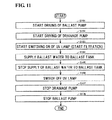
- FIG 11 is a flowchart explaining a process during ballast water uptake, according to an embodiment of the present invention. An outline of the process of ballast water uptake will be described with reference to Figs. 1 and 11 .
- the ballast water treatment apparatus 101 starts driving of the ballast pump 1.
- the ballast pump 1 takes up seawater as untreated water from the sea.
- the untreated water flows from the ballast pump 1 to the filtering device 2.
- cleaning of the filter 61 is performed in the filtering device 2 by using the untreated water (seawater).
- the untreated water after the cleaning of the filter 61 is returned to the sea.
- step S102 the ballast water treatment apparatus 101 starts driving of the drainage pump 4.
- step S103 the ballast water treatment apparatus 101 starts switching on of the UV lamps 142 of the ultraviolet irradiation device 3. Furthermore, the filtering device 2 starts filtration of the untreated water. However, until the switching on of the UV lamps 142 is completed, the untreated water filtered in the filtering device 2 is returned to the sea without being sent to the ballast tank 5, though the untreated water passes through the ultraviolet irradiation device 3.
- step S104 the untreated water is supplied as ballast water to the ballast tank 5. That is, the untreated water flowing from the ultraviolet irradiation device 3 is sent to the ballast tank 5.
- step S105 the supply of ballast water to the ballast tank 5 is stopped.
- an operator checks the water level of ballast water in the ballast tank 5, and performs an operation for stopping the supply of ballast water.
- This operation may be an operation of pushing the BWMS stop button 128 of the control device 111.
- the operator may operate the display panel 131 of the control device 112.
- step S106 the ballast water treatment apparatus 101 switches off the UV lamps 142 of the ultraviolet irradiation device 3. Untreated water filtered by the filtering device 2 passes through the ultraviolet irradiation device 3 and is returned to the sea. Next, the filtration of untreated water in the filtering device 2 is finished. In an embodiment, in this case, after the filtration of untreated water is finished, the filter 61 is cleaned in the filtering device 2 by using untreated water (seawater).
- step S107 the ballast water treatment apparatus 101 stops the drainage pump 4.
- step S108 the ballast water treatment apparatus 101 stops the ballast pump 1.
- FIG. 12 is a diagram illustrating a process of step S101 of Fig. 11 .
- the control device 111 starts driving of the ballast pump 1.
- the drainage pump 4 remains stopped.
- the control device 111 sets the valves 31, 32, and 35 to an open state and sets the other valves to a closed state.
- Untreated water is taken up from the sea by the ballast pump 1, and passes through the lines 10 and 11.
- the untreated water flows from the ballast pump 1 into the filtering device 2 through the lines 12 and 13.
- the untreated water is discharged from the filtering device 2 through the line 16. Note that since the valve 34 is closed, the untreated water does not flow from the filtering device 2 through the line 15.
- the filtering device 2 cleans the filter 61 using the untreated water.
- untreated water is ejected from the nozzle opening 67 while the filter 61 is rotated by the motor 90.
- Suspensoid adhering to the filter 61 is removed by a pressure of the untreated water and a rotating stream of water.
- the filter 61 is cleaned by using seawater (untreated water) introduced into the filtering device 2 while the valve 34 is closed, as described above. Prior to the supply of ballast water to the ballast tank 5, the filter 61 is cleaned. Accordingly, a problem of a decrease in the performance of a treatment of ballast water can be prevented.
- the untreated water is returned to the sea through the lines 16, 17, and 18.
- pipes forming the lines 16, 17, and 18 can also be cleaned.
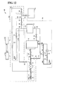
- FIG. 13 is a diagram illustrating a process of step S102 of Fig. 11 .
- the control device 111 starts driving of the drainage pump 4.
- the control device 111 can drive the drainage pump 4 automatically (for example, after the lapse of a certain time) subsequent to the driving of the ballast pump 1.
- the control device 111 drives the drainage pump 4 in response to an instruction input by the operator.
- the control device 111 further sets the valve 36 to an open state.
- the control device 111 receives, from the flow meter 53, a signal representing a flow rate of untreated water flowing through the line 18.
- the control device 111 controls the opening degree of the valve 36 so that, for example, the flow rate of untreated water flowing through the line 18 becomes 20 m 3 /h.
- This numerical value representing the flow rate is an example, and the flow rate of untreated water flowing through the line 18 is not limited thereto.
- the untreated water discharged from the filtering device 2 is returned to the sea through the line 16 and lines 17 and 18.
- the drainage discharge of the drainage pump 4 is smaller than the discharge rate of the ballast pump 1. Accordingly, in order to discharge, to the sea, untreated water supplied from the ballast pump 1 to the filtering device 2, not only the line 18 but also the line 17 is used.
- the filter 61 is cleaned as in step S101.
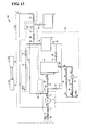
- FIG 14 is a diagram illustrating a process of step S103 of Fig. 11 .
- the control device 111 opens the valve 34 and closes the valve 35. Consequently, the untreated water filtered by the filtering device 2 is sent to the line 15.
- the untreated water is filtered by permeating from an outer circumferential surface of the filter 61 to an inner circumferential surface of the filter 61.
- the filtered untreated water is guided to the filtered water flow path 64 through the intake holes 81 provided in the central pipe 80, and sent to the ultraviolet irradiation device 3 through the line 15.
- control device 111 starts switching on of the UV lamps 142 of the ultraviolet irradiation device 3. A certain period of time is required until the illuminance of the UV lamps 142 reaches a predetermined illuminance. Accordingly, the amount of irradiation of ultraviolet light applied to the untreated water may be insufficient to kill microbes or bacteria contained in the untreated water. Therefore, the control device 111 closes the valve 40 and opens the valve 41. The untreated water passing through the ultraviolet irradiation device 3 passes through the lines 19 and 22 and is returned to the sea. Thus, it is possible to prevent untreated water for which the amount of irradiation of ultraviolet light is insufficient (i.e., for which the effect of killing is insufficient) from being sent to the ballast tank 5.
- the UV lamps 142 can be cooled by allowing the untreated water to pass through the ultraviolet irradiation device 3. Thus, it is possible to suppress overheating of the UV lamps 142 to which electricity is being supplied.
- FIG 15 is a graph illustrating a switching-on process of a UV lamp during water uptake.
- pumping of untreated water from a seawater environment to the ballast water treatment apparatus 101 is started at a time of t1.
- the amount of irradiation of ultraviolet light applied to the untreated water may be insufficient because, for example, air bubbles are contained in the untreated water. Therefore, the illuminance of ultraviolet light measured by each of the illuminance sensors 144a to 144c is low.
- the control device 111 controls an electric power supplied to each of the UV lamps 142 such that the illuminance of the UV lamp 142 becomes maximum.
- control device 111 sets a ratio of the electric power supplied to the UV lamp 142 to a maxim electric power of the UV lamp 142 to 100%.
- the control device 111 instructs the ratio (i.e., 100%) to the lamp power supply 143. This process can reduce the time required for the switching-on process of the UV lamps 142.
- the electric power supplied to each of the UV lamps 142 reaches the maximum electric power at a time of t2.
- the control device 111 gradually decreases the electric power supplied to the UV lamp 142. Accordingly, the illuminance of the UV lamp 142 temporarily reaches a peak and then gradually decreases. At a time of ts, the illuminance detected by each of the illuminance sensors 144a to 144c reaches a target value. Thus, the switching-on process of the UV lamps 142 is completed.
- the control device 111 controls the lamp power supply 143 so that the illuminance of each of the UV lamps 142 is maintained at the target value.
- the amount of electric power supplied to each of the UV lamps 142 is an amount of electric power predetermined so as to obtain a minimum illuminance necessary for killing microbes or bacteria in untreated water. Accordingly, the power consumption of the UV lamps 142 can be saved.
- control device 111 controls the electric power supplied to each of the UV lamps 142 so that the illuminance of the UV lamp 142 becomes a maximum value.
- the control device 111 decreases the illuminance of the UV lamp 142 to the target value.
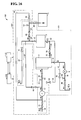
- FIG 16 is a diagram illustrating a process of step S104 of Fig. 11 .
- the control device 111 opens the valves 40 and 44, and closes the valve 41.
- the untreated water is filtered by the filtering device 2 and irradiated with ultraviolet light in the ultraviolet irradiation device 3.
- the untreated water that has been irradiated with ultraviolet light is stored as ballast water in the ballast tank 5.
- the control device 111 determines the openings of the valves 40 and 41 on the basis of a flow rate shown by the flow meter 54.
- the valve 32 is provided between the ballast pump 1 and the filtering device 2. Untreated water is discharged from the ballast pump 1 at a certain discharge pressure. However, after the untreated water passes through the valve 32, the pressure of the untreated water decreases. Some of the untreated water flowing in the filtering device 2 is suctioned by the drainage pump 4, thereby ensuring a flow rate of untreated water (ballast water) flowing through the line 15, the ultraviolet irradiation device 3, and the lines 20 and 21. That is, the performance of a treatment of ballast water can be ensured.
- the treatment of unfiltered water can be performed immediately after the completion of the switching-on process of the UV lamps 142. Accordingly, a start-up time of the ballast water treatment apparatus 101 can be shortened.
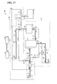
- FIG. 17 is a diagram illustrating a process of steps S105 and S106 of Fig. 11 .
- the supply of ballast water to the ballast tank 5 is stopped.
- the operator checks the water level of the ballast tank 5 and pushes the BWMS stop button 128. Consequently, an instruction for stopping the supply of ballast water is sent to the control device 111.
- the control device 111 closes the valves 40 and 44 and opens the valve 41. Consequently, as in the process of step S104 (refer to Fig. 14 ), the untreated water passing through the ultraviolet irradiation device 3 passes through the line 22 and is returned to the sea.
- control device 111 switches off the UV lamps 142 of the ultraviolet irradiation device 3. Also after the UV lamps 142 are switched off, untreated water is still allowed to pass through the ultraviolet irradiation device 3. Thus, the effect of cooling the UV lamps 142 can be obtained.
- FIG. 18 is a diagram illustrating a part of a process of step S107 of Fig. 11 .
- the control device 111 closes the valve 34 and opens the valve 35. Consequently, as in the process of step S102 (refer to Fig. 13 ), the untreated water flowing in the filtering device 2 is returned to the sea without being sent to the ultraviolet irradiation device 3.
- FIG 19 is a diagram illustrating a process subsequent to the process shown in Fig. 18 .
- the control device 111 stops the drainage pump 4. Furthermore, the control device 111 closes the valve 36. Consequently, as in the process of step S101 (refer to Fig. 12 ), the filtering device 2 discharges untreated water from the line 16 without filtering the untreated water. Subsequently, a process of step S108 is carried out, and the ballast pump 1 is stopped. Thus, the process during water uptake (process in the Ballast mode) is finished.
- Figure 20 is a flowchart explaining a process during discharge of ballast water, according to an embodiment of the present invention. An outline of a process during discharge of ballast water will be described with reference to Figs. 1 and 20 .
- step S201 the ballast water treatment apparatus 101 starts driving of the ballast pump 1. Valves are controlled so that ballast water stored in the ballast tank 5 is circulated in the ballast water treatment apparatus 101 by the ballast pump 1.
- step S202 switching on of the UV lamps 142 is started.
- step S203 discharge of the ballast water is started in step S203.
- the ballast water is taken out from the ballast tank 5 and sent to the ultraviolet irradiation device 3. After the ballast water is irradiated with ultraviolet light, the ballast water is discharged into the sea.
- step S204 the ballast water treatment apparatus 101 circulates the ballast water again. Furthermore, the ballast water treatment apparatus 101 switches off the UV lamps 142. The circulation of the ballast water is carried out for a predetermined period of time.
- step S205 the ballast water treatment apparatus 101 stops the ballast pump 1. Thus, the process is finished.
- ballast water is irradiated with ultraviolet light for a time and then discharged into the sea.
- ballast water is irradiated with ultraviolet light in order to kill microbes.
- microbes in water may not be completely killed.
- ballast water is irradiated with ultraviolet light by the ultraviolet irradiation device 3 immediately before the ballast water is discharged into the sea. This process further enhances the effect of preventing ballast water discharged into the sea from affecting the ecosystem in a seawater environment.
- the filtering process is omitted during discharge of ballast water.
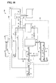
- FIG. 21 is a diagram illustrating a process of steps S201 and S202 of Fig. 20 .
- the control device 111 starts driving of the ballast pump 1.
- control device 111 sets the valves 44, 42, 33, and 40 to an open state and sets other valves to a closed state.
- Ballast water in the ballast tank 5 is pumped by the ballast pump 1 and passes through the lines 23 and 11.
- the ballast water pumped from the ballast pump 1 circulates by passing through the lines 21, 23, 11, 12, 14, 19, and 20. That is, the lines 21, 23, 11, 12, 14, 19, and 20 form a circulation path in which the ballast water circulates and receives ultraviolet light emitted from the UV lamps 142 of the ultraviolet irradiation device 3.
- Filtration by the filtering device 2 can be made unnecessary by allowing ballast water to pass through a path (line 14) which bypasses the filtering device 2. Accordingly, the process during discharge of ballast water can be simplified.
- control device 111 switches on the UV lamps 142 of the ultraviolet irradiation device 3.
- the UV lamps 142 can be cooled by allowing untreated water to pass through the ultraviolet irradiation device 3. Thus, it is possible to suppress overheating of the UV lamps 142 to which electricity is being supplied.
- FIG 22 is a graph illustrating a switching-on process of a UV lamp during discharge of water.
- circulation of ballast water is started in the ballast water treatment apparatus 101 at a time of t11.
- the control device 111 controls the lamp power supply 143 so as to supply a maximum electric power to each of the UV lamps 142. That is, the control device 111 sets a ratio of an electric power supplied to the UV lamp 142 to the maximum electric power of the UV lamp 142 to 100% and instructs the ratio (i.e., 100%) to the lamp power supply 143.
- the electric power supplied to the UV lamp 142 reaches the maximum electric power.
- the control device 111 sets, from the time of t12, the ballast water treatment apparatus to a state in which the apparatus can be operated. This process can reduce the time required until the ultraviolet irradiation process can be performed.
- the amount of irradiation of ultraviolet light applied to the ballast water can be increased. Accordingly, the ultraviolet irradiation process can be started within a short time from the start of the switching on of the UV lamps 142.
- the turbidity of the ballast water may increase temporarily.
- the turbidity of the ballast water temporarily increases due to swirl of precipitate deposited in the ballast tank 5.
- a maximum electric power is supplied to the UV lamp 142. That is, at the time of t12 and thereafter, a state where the maximum electric power is supplied to the UV lamp 142 is continued for a certain period of time.
- the control device 111 controls the lamp power supply 143 so that the electric power supplied to each of the UV lamps 142 decreases gradually.
- the control device 111 controls the lamp power supply 143 as shown by the curved line L2. That is, after the electric power supplied to each of the UV lamps 142 reaches the maximum electric power, the control device 111 controls the lamp power supply 143 so that the electric power supplied to the UV lamp 142 gradually decreases. In such a case, as in the case shown in Fig. 15 , the illuminance of the UV lamp 142 temporarily reaches a peak and then gradually decreases.
- the ballast water is not discharged from the ballast water treatment apparatus 101.
- the ballast water is irradiated with ultraviolet light and discharged from the ballast water treatment apparatus 101. Accordingly, the effect of killing microbes contained in the ballast water can be increased.
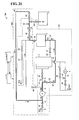
- FIG 23 is a diagram illustrating a process of step S203 of Fig. 21 .
- the control device 111 sets the valve 41 to an open state.
- the control device 111 sets the valve 40 to a closed state. Accordingly, the ballast water is irradiated with ultraviolet light when passing through the ultraviolet irradiation device 3. The ballast water then passes through the line 22 and is discharged into the sea.
- the lines 21, 23, 11, 12, 14, 19, and 22 form a discharge path for discharging ballast water from the ballast tank 5 that stores the ballast water.
- the ballast water passes through the discharge path and is discharged from the ballast tank 5, the ballast water is irradiated with ultraviolet light from the ultraviolet irradiation device 3. Accordingly, microbes in the ballast water can be killed.
- the circulation path and the discharge path are switched by opening one of the valves 40 and 41 and closing the other valve.
- the valves 40 and 41 form a switching portion for switching the path through which the ballast water flows between the circulation path and the discharge path.
- a path formed by the lines 21, 23, 11, 12, 14, and 19 is common to the circulation path and the discharge path.
- the UV lamps 142 are arranged between the line 15 and the line 19. That is, the UV lamps 142 are provided in the path common to the circulation path and the discharge path.
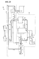
- FIG. 24 is a diagram illustrating a process of step S204 of Fig. 21 .
- the control device 111 sets the valve 40 to an open state.
- the control device 111 sets the valve 41 to a closed state. Consequently, the ballast water again passes through the circulation path of the ballast water treatment apparatus 101.
- control device 111 switches off the UV lamps 142 of the ultraviolet irradiation device 3. After the UV lamps 142 are switched off, the control device 111 still allows untreated water to pass through the ultraviolet irradiation device 3. Accordingly, the effect of cooling the UV lamps 142 can be obtained. Subsequently, in step S205, the control device 111 stops the ballast pump 1.
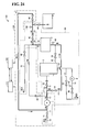
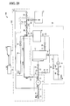
- FIG. 25 is a diagram illustrating intake of ballast water in the BYPASS mode.
- the control device 111 sets the valves 31, 43, 40, and 44 to an open state and sets the other valves to a closed state.
- the control device 111 starts driving of the ballast pump 1.
- Seawater passes through the lines 10 and 11 and is pumped by the ballast pump 1.
- the seawater discharged from the ballast pump 1 passes through the lines 12, 24, 20, and 21 and is sent to the ballast tank 5.
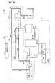
- FIG. 26 is a diagram illustrating discharge of ballast water in the BYPASS mode.
- the control device 111 sets the valves 41, 42, 43, and 44 to an open state and sets the other valves to a closed state.
- the control device 111 starts driving of the ballast pump 1.
- ballast water is pumped from the ballast tank 5 by the ballast pump 1 and passes through the lines 23 and 11.
- the seawater discharged from the ballast pump 1 passes through the lines 12, 24, and 22 and is discharged into the sea.
- the filter 61 of the filtering device 2 is cleaned.
- the filter 61 is cleaned by ejecting untreated water (seawater pumped by the ballast pump 1) onto an outer circumferential surface of the filter 61.
- reverse cleaning of the filter 61 may be performed.
- Figure 27 is a diagram showing a structural example for performing reverse cleaning of a filter 61 of a filtering device 2.
- a reverse cleaning device 2A includes a cleaning water tank 68, valves 37 and 38, and lines 25, 26, and 27 realized by arranging a pipe.
- cleaning water is prepared.
- valves 32, 35, and 34 are set to an open state, and a valve 33 and the valve 37 are set to a closed state.
- the valve 38 for releasing a pressure is provided in the line 26 and on an upper portion of the cleaning water tank 68.
- the valve 38 is set to an open state.
- the valve 37 is provided in the line 25 branched from a line 15.
- filtered water from a filtering device 2 flows in the cleaning water tank 68 and is stored in the cleaning water tank 68.
- the valve 37 is set to a closed state.
- filtered water may not necessarily be used as the cleaning water.
- tap water or the like may be introduced into the cleaning water tank 68.
- the control device 111 sets the valves 32, 33, and 35 to a closed state to stop a usual filtering process.
- the control device 111 sets the valve 37 to an open state and sets the valve 38 to a closed state.
- a case 63 of the filtering device 2 is connected to the cleaning water tank 68 through the line 15, and all the other flow paths are closed.
- compressed air or the like is allowed to flow in the pressurizing pipe 27 to apply a pressure to the cleaning water.
- the cleaning water may be pressurized in a state where the valve 37 is closed, and the valve 37 may then be opened.
- the inside of the whole of the case 63, the line 15, and the cleaning water tank 68 is maintained in a pressurized state.
- the valve 35 is opened (set to an open state). Consequently, the cleaning water passes from the cleaning water tank 68 to the line 15 and permeates through the filter 61.
- the cleaning water passes from the case 63 to the line 16 and is discharged to the outside at one time. That is, the cleaning water flows through the filter 61 serving as a filtration membrane within a short time in a direction opposite to a direction in which water flows during filtering.
- the cleaning water flows through the filtered water flow path 64 and is ejected from the intake holes 81 of the central pipe 80.
- the cleaning water passes through the filter 61 from an inner circumferential surface of the filter 61 to an outer circumferential surface of the filter 61. Consequently, substances, for example, adhering to the outer circumferential surface of the filter 61 are removed from the outer circumferential surface of the filter 61, and thus the filter 61 is cleaned.
- the control device 111 sets the valves 32, 34, and 35 to an open state and sets the valves 33 and 37 to a closed state so that the filtering device 2 performs the usual filtering process. In this state, since cleaning water can be stored again in the cleaning water tank 68 by opening the valves 37 and 38, the cleaning operation can be repeated.
- the motor 90 may be stopped during the cleaning operation.
- the motor 90 is preferably driven because a high cleaning effect is obtained by performing reverse cleaning of the filter 61 while the filter 61 is rotated.
- the reason for this is that, in addition to the pressure of cleaning water from the inside of the cylinder, a centrifugal force due to the rotation of the cylinder is applied to substances adhering to the outer circumferential surface of the cylindrical, pleated filter 61, and thus filtered substances are more easily removed.
- the filter 61 can be effectively cleaned by performing reverse cleaning of the filter 61 in a rotational state, as described above. Furthermore, even when vibrations of the whole filter 61 are added to the rotation, an increase in the effect of cleaning the filter 61 can be expected.
- the filter 61 may be cleaned by using a chemical.
- a chemical inlet 70 is provided on a lid portion of the case 63.
- the filtering device 2 can be operated for a long period of time by performing reverse cleaning of the filter 61.
- the lifetime of the filter 61 can be extended by using the cleaning with a chemical in combination.
- the cleaning with a chemical can be performed by the following procedure using the chemical inlet.
- the filter 61 may be stopped or may be in a rotational state. All the valves are set to a closed state so that the inside of the case 63 is maintained in a state in which untreated water or filtered water is left and the filter 61 is immersed in water. In this state, a chemical for cleaning is poured from the chemical inlet 70.
- the rotational state is maintained as it is.
- the motor 90 is rotated so that the filter 61 becomes in a rotational state. This state is maintained for a certain period of time until the chemical spreads over the rotating filter 61 and the outer circumferential surface of the filter 61 is sufficiently cleaned.
- the valve 35 is opened to discharge water (containing the chemical) in the case 63.
- a neutralizing solution may be further poured before the discharge of water or a process of neutralization or the like may be performed after the discharge of water depending on the type of chemical used.
- the ballast water treatment apparatus 101 includes the discharge path for discharging ballast water from the ballast tank 5 that stores the ballast water, and the ultraviolet irradiation device 3 that irradiates the ballast water passing through the discharge path with ultraviolet light.
- the ballast water is discharged from the ballast tank 5 through the discharge path, the ballast water is irradiated with ultraviolet light from the ultraviolet irradiation device 3. Consequently, microbes in the ballast water can be killed. Since the purification treatment of ballast water can be performed immediately before the discharge of the ballast water, the possibility of an effect on the ecosystem in a seawater environment can be more reliably reduced.
- the control devices 111 and 112 are configured as devices capable of not only controlling the ballast water management system 100 but also setting the operation mode of the ballast water management system 100 by an operator.
- the number of setting devices may be two or more, and the number of control devices of the ballast water management system 100 may be one.
- the ballast water management system may be configured so that the one control device receives setting determined in the plurality of setting devices.
- the control device allows the ballast water management system 100 to operate in the operation mode. Also in this configuration, it is possible to prevent the ballast water management system 100 from operating in an operation mode that is not intended by an operator.
- the operator can use a setting device arranged near the operator. Thus, convenience of the operator can be enhanced.
Landscapes
- Engineering & Computer Science (AREA)
- Chemical & Material Sciences (AREA)
- Environmental & Geological Engineering (AREA)
- Toxicology (AREA)
- Health & Medical Sciences (AREA)
- Life Sciences & Earth Sciences (AREA)
- Organic Chemistry (AREA)
- Water Supply & Treatment (AREA)
- Hydrology & Water Resources (AREA)
- Mechanical Engineering (AREA)
- Ocean & Marine Engineering (AREA)
- Combustion & Propulsion (AREA)
- Public Health (AREA)
- General Health & Medical Sciences (AREA)
- Physical Water Treatments (AREA)
- Filtration Of Liquid (AREA)
Abstract
Description
- The present invention relates to an apparatus for treating ballast water stored in a ship and a ballast water management system including an apparatus for treating ballast water.
- Ballast water is seawater carried in a ship to provide safe voyage in the sea when the ship carries no cargo. Ballast water is taken up from a seawater environment around a ship at a departure port of the ship and loaded into the ship. The ballast water is discharged around the ship at a destination port of the ship.
- The ballast water is discharged into a seawater environment different from a seawater environment where the ballast water is taken up. Organisms in the ballast water are transported to a seawater environment different from their original habitat, resulting in a problem in that the organisms in the ballast water affect the ecosystem in the seawater environment into which the ballast water is discharged.
- In order to solve this problem, various methods for performing a purification treatment of ballast water have been developed. For example, Japanese Unexamined Patent Application Publication No.
2013-23187 - The above apparatus is provided in order to solve a problem in that the amount of ultraviolet irradiation is insufficient in a state where untreated water has a very high turbidity. Specifically, the treatment apparatus disclosed in the above document discharges pumped untreated water around a ship without allowing the untreated water to pass through the ultraviolet irradiation unit until the illuminance of an ultraviolet lamp reaches a predetermined value. When the illuminance of the ultraviolet lamp reaches the predetermined value, the pumped untreated water is allowed to pass through the ultraviolet irradiation unit and poured into a ballast tank.
- PTL 1: Japanese Unexamined Patent Application Publication No.
2013-23187 - Japanese Unexamined Patent Application Publication No.
2013-23187 - An object of the present invention is to provide a technique for more reliably reducing the possibility that ballast water will affect the ecosystem in a seawater environment.
- A ballast water treatment apparatus according to an aspect of the present invention includes a discharge path for discharging ballast water from a ballast tank that stores the ballast water, an ultraviolet irradiation device that includes an ultraviolet lamp and that irradiates the ballast water passing through the discharge path with ultraviolet light, a circulation path formed so that the ballast water circulates therethrough and is irradiated with ultraviolet light emitted from the ultraviolet lamp, a switching portion for switching a path through which the ballast water flows between the circulation path and the discharge path, and a control device that controls the switching portion so that the ballast water flows through the circulation path during a switching-on process of the ultraviolet lamp and controls the switching portion so that the ballast water flows through the discharge path when the switching on of the ultraviolet lamp is completed.
- According to this configuration, when the ballast water is discharged from the ballast tank through the discharge path, the ballast water is irradiated with ultraviolet light emitted from the ultraviolet irradiation device. Consequently, microbes in the ballast water can be killed. Since a purification treatment of ballast water can be performed immediately before the discharge of the ballast water, the possibility of an effect on the ecosystem in a seawater environment can be more reliably reduced. Furthermore, during the switching-on process of the ultraviolet lamp, the ballast water passes through the circulation path and thus is not discharged from the ballast water treatment apparatus. In a state where the amount of ultraviolet irradiation becomes sufficient after the switching-on process of the ultraviolet lamp is completed, the ballast water is irradiated with ultraviolet light and discharged from the ballast water treatment apparatus. Thus, the effect of killing microbes contained in ballast water can be enhanced.
- The circulation path and the discharge path may be partially common to each other or may each be independently arranged.
- A ballast water management system according to another aspect of the present invention includes the above ballast water treatment apparatus, a ballast tank that stores the ballast water, and a pump that pumps the ballast water from the ballast tank and sends the ballast water to the discharge path.
- According to this configuration, since a purification treatment of ballast water can be performed immediately before the discharge of ballast water, the possibility of an effect on the ecosystem in a seawater environment can be more reliably reduced.
- According to the present invention, the possibility that ballast water will affect the ecosystem in a seawater environment can be more reliably reduced. Brief Description of Drawings
-
- [
Fig. 1] Figure 1 is an overall diagram of a ballast water management system according to an embodiment of the present invention. - [
Fig. 2] Figure 2 is a schematic view showing a structural example of a control panel on the main body side of a ballast water treatment apparatus. - [
Fig. 3] Figure 3 is a schematic view showing a structural example of a control panel on the bridge side of a ship. - [
Fig. 4] Figure 4 is a view illustrating a structural example of a filtering device shown inFig. 1 . - [
Fig. 5] Figure 5 is a cross-sectional view taken along line V-V ofFig. 4 . - [
Fig. 6] Figure 6 is a schematic perspective view illustrating a typical structure of a filter shown inFig. 4 . - [
Fig. 7] Figure 7 is a diagram showing a structural example of an ultraviolet irradiation device shown inFig. 1 . - [
Fig. 8] Figure 8 is a table showing control contents determined by a combination of setting of a control device on the ballast water treatment apparatus side and setting of a control device on the bridge side. - [
Fig. 9] Figure 9 is a flowchart showing a flow of the control shown inFig. 8 . - [
Fig. 10] Figure 10 is a flowchart explaining a flow of an operation of a ballast water treatment apparatus. - [
Fig. 11] Figure 11 is a flowchart explaining a process during ballast water uptake, according to an embodiment of the present invention. - [
Fig. 12] Figure 12 is a diagram illustrating a process of step S101 ofFig. 11 . - [
Fig. 13] Figure 13 is a diagram illustrating a process of step S102 ofFig. 11 . - [
Fig. 14] Figure 14 is a diagram illustrating a process of step S103 ofFig. 11 . - [
Fig. 15] Figure 15 is a graph illustrating a switching-on process of UV lamps during water uptake. - [
Fig. 16] Figure 16 is a diagram illustrating a process of step S104 ofFig. 11 . - [
Fig. 17] Figure 17 is a diagram illustrating a process of steps S105 and S106 ofFig. 11 . - [
Fig. 18] Figure 18 is a diagram illustrating a part of a process of step S107 ofFig. 11 . - [
Fig. 19] Figure 19 is a diagram illustrating a process subsequent to the process shown inFig. 18 . - [
Fig. 20] Figure 20 is a flowchart explaining a process during discharge of ballast water, according to an embodiment of the present invention. - [
Fig. 21] Figure 21 is a diagram illustrating a process of steps S201 and S202 ofFig. 20 . - [
Fig. 22] Figure 22 is a graph illustrating a switching-on process of UV lamps during discharge of water. - [
Fig. 23] Figure 23 is a diagram illustrating a process of step S203 ofFig. 21 . - [
Fig. 24] Figure 24 is a diagram illustrating a process of step S204 ofFig. 21 . - [
Fig. 25] Figure 25 is a diagram illustrating intake of ballast water in a BYPASS mode. - [
Fig. 26] Figure 26 is a diagram illustrating discharge of ballast water in a BYPASS mode. - [
Fig. 27] Figure 27 is a diagram showing a structural example for performing reverse cleaning of a filter of a filtering device. - 1 ballast pump, 2 filtering device, 2A reverse cleaning device, 3 ultraviolet irradiation device, 4 drainage pump, 5 ballast tank, 10 to 27 line, 27 pressurizing pipe, 31 to 36, 40 to 44 valve, 51, 52, 53, 54 flow meter, 61 filter, 62 untreated water nozzle, 63, 141 case, 64 filtered water flow path, 65 discharge flow path, 66 untreated water flow path, 67 nozzle opening, 68 cleaning water tank, 70 chemical inlet, 71 outer cylindrical portion, 72 lid portion, 73 bottom portion, 80 central pipe, 81 intake hole, 90 motor, 91 motor cover, 100 ballast water management system, 101 ballast water treatment apparatus, 102 bypass system, 111, 112 control device, 121, 131 display panel, 122 bypass lamp, 123 BWMS enable lamp, 124, 132 operation mode switch, 125 processing mode switch, 126, 133 BWMS preparation lamp, 127 BWMS start button, 128 BWMS stop button, 129, 135 emergency stop button, 134 start button, 142 UV lamp, 143 lamp power supply, 144a to 144c illuminance sensor, C axis line, L1 straight line, L2 curved line.
- A ballast water treatment apparatus according to an aspect of the present invention includes a discharge path for discharging ballast water from a ballast tank that stores the ballast water, an ultraviolet irradiation device that includes an ultraviolet lamp and that irradiates the ballast water passing through the discharge path with ultraviolet light, a circulation path formed so that the ballast water circulates therethrough and is irradiated with ultraviolet light emitted from the ultraviolet lamp, a switching portion for switching a path through which the ballast water flows between the circulation path and the discharge path, and a control device that controls the switching portion so that the ballast water flows through the circulation path during a switching-on process of the ultraviolet lamp and controls the switching portion so that the ballast water flows through the discharge path when the switching on of the ultraviolet lamp is completed.
- According to this configuration, when the ballast water is discharged from the ballast tank through the discharge path, the ballast water is irradiated with ultraviolet light emitted from the ultraviolet irradiation device. Consequently, microbes in the ballast water can be killed. Since a purification treatment of ballast water can be performed immediately before the discharge of the ballast water, the possibility of an effect on the ecosystem in a seawater environment can be more reliably reduced. Furthermore, during the switching-on process of the ultraviolet lamp, the ballast water passes through the circulation path and thus is not discharged from the ballast water treatment apparatus. In a state where the amount of ultraviolet irradiation becomes sufficient after the switching-on process of the ultraviolet lamp is completed, the ballast water is irradiated with ultraviolet light and discharged from the ballast water treatment apparatus. Thus, the effect of killing microbes contained in ballast water can be enhanced.
- The circulation path and the discharge path may be partially common to each other or may each be independently arranged.
- Preferably, in the switching-on process of the ultraviolet lamp, when an electric power supplied to the ultraviolet lamp reaches a maximum electric power for the ultraviolet lamp, the control device permits the switching portion to switch from the circulation path to the discharge path.
- According to this configuration, it is possible to reduce the time required until the ultraviolet irradiation process can be performed. For example, immediately after starting pumping of ballast water from the ballast tank, turbidity of the ballast water may increase temporarily. By setting the electric power supplied to the ultraviolet lamp to the maximum electric power for the ultraviolet lamp, the amount of irradiation of ultraviolet light applied to the ballast water can be increased. Accordingly, the ultraviolet irradiation process can be started within a short time from the start of the switching on of the ultraviolet lamp.
- Preferably, the ultraviolet lamp is provided in a path common to the discharge path and the circulation path. After the ballast water is discharged from the ballast tank, the control device switches off the ultraviolet lamp and switches the path of the ballast water from the discharge path to the circulation path.
- According to this configuration, after the ultraviolet lamp is switched off, the ultraviolet lamp can be cooled by seawater passing through the ultraviolet irradiation device.
- Preferably, the ballast water treatment apparatus further includes a filtering device that filters the ballast water and that supplies the filtered ballast water to the ultraviolet irradiation device when the ballast water is stored in the ballast tank. The circulation path and the discharge path include a common path that bypasses the filtering device.
- According to this configuration, ballast water filtered by the filtering device is stored in the ballast tank. Consequently, while the ballast water is discharged from the ballast tank, filtration by the filtering device can be made unnecessary by allowing the ballast water to pass through the path which bypasses the filtering device. Accordingly, the process during discharge of the ballast water can be simplified.
- A ballast water management system according to another aspect of the present invention includes the above ballast water treatment apparatus, a ballast tank that stores the ballast water, and a pump that pumps the ballast water from the ballast tank and sends the ballast water to the discharge path.
- According to this configuration, since a purification treatment of ballast water can be performed immediately before the discharge of the ballast water, the possibility of an effect on the ecosystem in a seawater environment can be more reliably reduced.
- Preferably, the ballast water management system further includes a bypass system for feeding seawater into the ballast tank and discharging seawater from the ballast tank while bypassing the ballast water treatment apparatus.
- According to this configuration, for example, even in the case where treatment of seawater by the ballast water treatment apparatus is not necessary or even in the case where seawater cannot be treated by the ballast water treatment apparatus, seawater can be fed into or discharged from the ballast tank.
- An embodiment of the present invention will now be described in detail with reference to the drawings. In the drawings, the same or corresponding components are assigned with the same reference numerals, and a description thereof is not repeated.
- In the present embodiment, the term "ballast water" refers to seawater stored in a ballast tank. Accordingly, in this specification, in the case where ballast water is seawater, an expression "ballast water (seawater)" may be used.
- In the present embodiment, the term "untreated water" refers to seawater that is treated by a ballast water treatment apparatus according to the present embodiment. As described below, in the present embodiment, the term "untreated water" covers not only seawater taken up from a seawater environment to the ballast water treatment apparatus but also "ballast water". In the case where the term "ballast water" and the term "untreated water" are not necessarily distinguished from each other, the term "seawater" may be used.
-
Figure 1 is an overall diagram of a ballast water management system according to an embodiment of the present invention. Referring toFig. 1 , a ballastwater management system 100 according to an embodiment of the present invention is installed in a ship (not shown). When the ship departs from a port, the ballastwater management system 100 takes up seawater from a seawater environment around the ship and stores the seawater as ballast water in aballast tank 5. On the other hand, in a port of call of the ship, the ballastwater management system 100 discharges the ballast water stored in theballast tank 5 into a seawater environment around the ship. Theballast tank 5 may be separated into a plurality of sections. - The ballast
water management system 100 includes a ballastwater treatment apparatus 101, abypass system 102, andcontrol devices water treatment apparatus 101 and thebypass system 102 are main components of the ballastwater management system 100 and can be constituted as a ballast water management apparatus. - While taking up seawater from a seawater environment around the ship, the ballast
water treatment apparatus 101 performs a purification treatment of the seawater. Furthermore, while discharging ballast water (seawater) from theballast tank 5, the ballastwater treatment apparatus 101 can perform a purification treatment of the ballast water stored in the ballast tank. In the present embodiment, the term "purification" covers removal, killing, and inactivation of microbes contained in seawater. - On the other hand, while taking up seawater from a seawater environment around the ship, the
bypass system 102 can load the uptaken seawater into theballast tank 5 while the seawater bypasses the ballastwater treatment apparatus 101. Furthermore, while ballast water (seawater) is discharged from theballast tank 5, thebypass system 102 can discharge the ballast water into the sea while the ballast water bypasses the ballastwater treatment apparatus 101. Specifically, thebypass system 102 forms a path for feeding ballast water into theballast tank 5 and discharging the ballast water from theballast tank 5 while the ballast water bypasses the ballastwater treatment apparatus 101. For example, even in the case where treatment of seawater by the ballastwater treatment apparatus 101 is not necessary or even in the case where seawater cannot be treated by the ballastwater treatment apparatus 101, seawater can be fed into or discharged from theballast tank 5 through thebypass system 102. - The ballast
water treatment apparatus 101 and thebypass system 102 share some of components. In the case where thebypass system 102 has been already installed in a ship, the ballastwater management system 100 according to an embodiment of the present invention can be realized by adding the ballastwater treatment apparatus 101. Accordingly, the ballastwater management system 100 according to an embodiment of the present invention can be installed in the ship without significantly changing existing facilities. - The ballast
water treatment apparatus 101 includes aballast pump 1, afiltering device 2, anultraviolet irradiation device 3, a drainage pump 4,lines 10 to 22 for passing seawater,valves 31 to 36, 40, 41, and 44, and flowmeters - The
line 10 is a line for taking seawater from a seawater environment. Theline 11 is a line for passing the seawater that flows into theballast pump 1. Theline 12 is a line for passing the seawater that flows from theballast pump 1. Theballast pump 1 suctions seawater from thelines line 12. - The
line 12 is branched into theline 13 and theline 14. Theline 13 is a line for introducing the seawater into thefiltering device 2. Theline 14 forms a path that joins to theline 15 while bypassing thefiltering device 2. Thevalve 32 controls a flow rate of the seawater flowing through theline 13. Thevalve 33 controls a flow rate of the seawater flowing through theline 14. - The
filtering device 2 filters seawater that flows in thefiltering device 2 through theline 13. The filtered seawater flows from thefiltering device 2 through theline 15. Theline 15 guides the seawater filtered by thefiltering device 2 to theultraviolet irradiation device 3. That is, theline 15 forms a path for supplying the seawater filtered by thefiltering device 2 to theultraviolet irradiation device 3. Theflow meter 52 measures a flow rate of the seawater flowing through theline 15. - On the other hand, seawater that has not been filtered by the
filtering device 2 is discharged from thefiltering device 2 through theline 16. Theline 17 is branched from theline 16. Thelines 16 to 18 form a discharge water path for discharging seawater remaining in thefiltering device 2. - The
line 17 is a line for discharging the seawater that flows from theline 16 to the sea. Thevalve 35 is provided in theline 17 and controls a flow rate of the seawater flowing through theline 17. - The
line 16 is connected to an inlet of the drainage pump 4. Theline 18 is a line for passing the seawater that flows from the drainage pump 4. Theline 18 joins to theline 17. - The seawater discharged from the drainage pump 4 flows through the
line 18 and is discharged into the sea. Thevalve 36 is provided in theline 18 and controls a flow rate of the seawater flowing through theline 18. Theflow meter 53 measures a flow rate of the seawater flowing through theline 18. - The drainage pump 4 is smaller than the
ballast pump 1. Specifically, a discharge capacity of the drainage pump 4 is lower than the discharge capacity of theballast pump 1. By using a small pump as the drainage pump 4, a reduction in the size of the ballastwater treatment apparatus 101 can be realized. - The
ultraviolet irradiation device 3 includes an ultraviolet (UV) lamp (not shown). The seawater flowing through theline 15 is passed through theultraviolet irradiation device 3. The seawater passing through theultraviolet irradiation device 3 is irradiated with ultraviolet light emitted from the ultraviolet lamp. Untreated water is filtered by a filter 61 (refer toFig. 4 ) and then irradiated with ultraviolet light in theultraviolet irradiation device 3. Accordingly, even when a small UV lamp is used, an effect of killing microbes inhabiting in the filtered seawater can be obtained. By using a small UV lamp in theultraviolet irradiation device 3, advantages such as a reduction in the size of the device and saving of power consumption can be obtained. - The
line 19 is a line for passing the seawater that flows from theultraviolet irradiation device 3. Theline 20 is a line for branching, from theline 19, the seawater that flows from theultraviolet irradiation device 3 and guiding the seawater to theballast tank 5. Theline 21 is connected to theline 20 through thevalve 40. Theline 21 is a line for pouring the seawater to theballast tank 5. That is, thelines ultraviolet irradiation device 3 to theballast tank 5. - Note that the
line 21 also functions as a line for discharging seawater from theballast tank 5. Aflow meter 54 measures a flow rate of seawater flowing through theline 21. - The
line 22 is branched from theline 19 and forms a path for discharging the seawater that flows from theultraviolet irradiation device 3 through theline 19 to the sea. Thevalve 41 is provided in theline 22 and controls a flow rate of the seawater flowing through theline 22. - Each of the
valves valve 34 is, for example, an on-off valve. Thevalve 34 switches the state thereof between an open state and a closed state in accordance with a signal input to thevalve 34. Thevalve 34 may be a proportional control valve. - The
bypass system 102 includes aballast pump 1,lines 10 to 12 and 20 to 24, andvalves ballast pump 1, thelines valves water treatment apparatus 101 and thebypass system 102. Therefore, a detailed description of these components is not repeated below. - The
line 23 is connected to theline 21 through thevalve 42. Thevalve 42 controls a flow rate of seawater flowing through theline 23. - The
line 24 is branched from theline 19 and connected to theline 12. Thevalve 43 is provided in theline 24 and controls a flow rate of seawater flowing through theline 24. - Each of the
valves - The ballast
water management system 100 further includes thecontrol devices control devices - The
control devices water management system 100 in accordance with the instruction. That is, thecontrol devices control devices ballast pump 1 and the drainage pump 4. Furthermore, thecontrol devices Fig. 1 . Furthermore, thecontrol devices ultraviolet irradiation device 3. - The
control devices control device 111 can grasp its setting and transmit information relating to the setting to thecontrol device 112. Similarly, thecontrol device 112 can grasp its setting and transmit information relating to the setting to thecontrol device 111. Accordingly, thecontrol device 111 and thecontrol device 112 can be installed in separate places. - For example, the
control device 111 is installed near the ballastwater treatment apparatus 101. On the other hand, thecontrol device 112 is installed in, for example, a bridge. In accordance with this arrangement of thecontrol devices water treatment apparatus 101 and the bypass system 102) by using thecontrol device 112 in the bridge. - The operator can control the operation and stop of the ballast
water management system 100 by operating any one of thecontrol devices control devices water management system 100 between a ballast water treatment mode (referred to as "BWMS" (ballast water management system) mode in the present embodiment) and a bypass ("BYPASS") mode. The ballast water treatment mode is a mode in which the ballastwater treatment apparatus 101 is operated. The bypass mode is a mode in which thebypass system 102 is operated while the ballastwater treatment apparatus 101 is stopped. - Furthermore, in the case where the operation mode of the ballast
water management system 100 is the BWMS mode, the operator can switch a processing mode by operating any one of thecontrol devices - The "Manual mode" is a mode in which an operator specifies a particular valve in operating any of the
control devices water management system 100 performs a process including taking up seawater from the sea, treating the seawater, and pouring the treated seawater into theballast tank 5. The "De-Ballast mode" is a mode in which the ballastwater management system 100 performs a process of discharging ballast water (seawater) stored in theballast tank 5 to the sea. In the "Ballast mode" and the "De-Ballast mode", each of the valves is automatically controlled by thecontrol device - In an embodiment, the
control devices Figure 2 is a schematic view showing a structural example of a control panel on the main body side of a ballast water treatment apparatus. Referring toFig. 2 , a control device 111 (control panel) includes adisplay panel 121, abypass lamp 122, a BWMS enablelamp 123, anoperation mode switch 124, aprocessing mode switch 125, aBWMS preparation lamp 126, aBWMS start button 127, aBWMS stop button 128, and anemergency stop button 129. - The
display panel 121 displays, for example, an operation state of the ballastwater management system 100. In an embodiment, thedisplay panel 121 has a function of a touch panel. With this structure, an operator can input various types of setting to thecontrol device 111 by touching the display panel 121 (touch panel). - The
bypass lamp 122 is a lamp for indicating that the operation mode of the ballastwater management system 100 is in the BYPASS mode. When the operation mode of the ballastwater management system 100 is in the BYPASS mode, thebypass lamp 122 switches on. On the other hand, when the operation mode of the ballastwater management system 100 is in the BWMS mode or when the setting of the operation mode of the ballastwater management system 100 differs between thecontrol device 111 and thecontrol device 112, thebypass lamp 122 switches off. - The BWMS enable
lamp 123 is a lamp for indicating a state in which the ballastwater treatment apparatus 101 can be used. The "state in which the ballastwater treatment apparatus 101 can be used" refers to a state in which, in both thecontrol device 111 and thecontrol device 112, the operation mode of the ballastwater management system 100 is set to the BWMS mode. In this case, the BWMS enablelamp 123 switches on. - On the other hand, when the setting of the operation mode of the ballast
water management system 100 differs between thecontrol device 111 and thecontrol device 112, the ballastwater treatment apparatus 101 is in a state in which the ballastwater treatment apparatus 101 cannot be used. In this case, the BWMS enablelamp 123 blinks. When the operation mode of the ballastwater management system 100 is in the BYPASS mode, the BWMS enablelamp 123 switches off. In this manner, the BWMS enablelamp 123 varies its indication form through switched on, blinking, and switched off. Thus, the operator can easily see whether or not the setting of the operation mode is the same between thecontrol device 111 and thecontrol device 112. - The
operation mode switch 124 is a switch used by the operator to notify thecontrol device 111 of the operation mode of the ballastwater treatment apparatus 101. Specifically, theoperation mode switch 124 is configured so that the operation mode of the ballastwater treatment apparatus 101 can be switched between the BYPASS mode and the BWMS mode. - The
processing mode switch 125 is a switch for instructing the processing mode of the ballastwater treatment apparatus 101 to thecontrol device 111 by the operator when the BWMS mode is selected. Specifically, theprocessing mode switch 125 is configured so that the processing mode of the ballastwater treatment apparatus 101 can be switched among the "Manual mode", the "Ballast mode", and the "De-Ballast mode". - The
BWMS preparation lamp 126 blinks during start-up of the ballastwater treatment apparatus 101. When the start-up of the ballastwater treatment apparatus 101 is completed, the blinking rate of theBWMS preparation lamp 126 increases. TheBWMS preparation lamp 126 becomes sufficiently bright so as to distinguish the state where the ballastwater treatment apparatus 101 is under start-up from the state where the start-up of the ballastwater treatment apparatus 101 is completed. Accordingly, theBWMS preparation lamp 126 may switch on during the start-up of the ballastwater treatment apparatus 101, and theBWMS preparation lamp 126 may blink when the start-up of the ballastwater treatment apparatus 101 is completed. The term "switched on" refers to a state in which light is continuously emitted. The term "blinking" refers to a state in which a light-emitting state and a non-light-emitting state are alternately repeated. - The
BWMS start button 127 is an operation bottom used by the operator to instruct thecontrol device 111 to start a purification treatment of seawater using the ballastwater treatment apparatus 101. TheBWMS stop button 128 is an operation bottom used by the operator to instruct thecontrol device 111 to stop the purification treatment of seawater using the ballastwater treatment apparatus 101. When the operator pushes theBWMS start button 127, thecontrol device 111 receives an instruction of the start of the purification treatment of seawater. When the operator pushes theBWMS stop button 128, thecontrol device 111 receives an instruction of the stop of the treatment of purifying seawater. - The
emergency stop button 129 is an operation button for stopping the operation of the ballastwater treatment apparatus 101 in case of emergency. -
Figure 3 is a schematic view showing a structural example of a control panel on the bridge side of a ship. Referring toFig. 3 , the control device 112 (control panel) includes adisplay panel 131, anoperation mode switch 132, aBWMS preparation lamp 133, and astart button 134, and anemergency stop button 135. - The
display panel 131 displays an operation state of the ballastwater management system 100. For example, thedisplay panel 131 displays an operation mode set by an operator. - As in the
display panel 121 shown inFig. 2 , in an embodiment, thedisplay panel 131 may have a function of a touch panel. With this structure, the function possessed by thecontrol device 111 shown inFig. 2 can be realized by the display panel 131 (touch panel). For example, in the case where the operation mode is set to the BWMS mode, the operator can select the processing mode and notify thecontrol device 112 of the selected processing mode by touching the display panel 131 (touch panel). In this case, thedisplay panel 131 can display the selected processing mode. - Similarly to the
operation mode switch 124 shown inFig. 2 , theoperation mode switch 132 is a switch used by the operator to notify thecontrol device 112 of the operation mode of the ballastwater treatment apparatus 101. Theoperation mode switch 132 is configured so that the operation mode of the ballastwater treatment apparatus 101 can be switched between the BYPASS mode and the BWMS mode. - The
BWMS preparation lamp 133 performs the same operation as that of theBWMS preparation lamp 126 shown inFig. 2 . Specifically, theBWMS preparation lamp 133 blinks during start-up of the ballastwater treatment apparatus 101. When the start-up of the ballastwater treatment apparatus 101 is completed, the blinking rate of theBWMS preparation lamp 133 increases. - The
start button 134 is an operation button used by the operator to notify thecontrol device 112 of the operation of the ballastwater management system 100 in a selected operation mode. Theemergency stop button 135 is an operation button for stopping the operation of the ballastwater treatment apparatus 101 in case of emergency. - As shown in
Figs. 2 and3 , thecontrol device 111 and thecontrol device 112 have different structures. However, the structures of thecontrol devices control device 111 and thecontrol device 112 may have the same structure. In the description below, it is assumed that thedisplay panels -
Figure 4 is a view illustrating a structural example of thefiltering device 2 shown inFig. 1 .Figure 5 is a cross-sectional view taken along line V-V ofFig. 4 . - Referring to
Figs. 4 and5 , seawater which is untreated water passes through a untreatedwater flow path 66 corresponding to theline 13 ofFig. 1 and is supplied to the inside of acase 63. Afilter 61 having a cylindrical shape is provided in thecase 63. An axis line C denotes a central axis of the filter 61 (cylinder). In other words, thefilter 61 is arranged so as to surround the axis line C. - A
motor 90 is connected to the central axis of thefilter 61. When an electric power is supplied from a driving device (not shown), themotor 90 rotates thefilter 61 around the axis line C as a center. Themotor 90 is covered with amotor cover 91. Themotor 90 is controlled by, for example, thecontrol device 111. - An upper surface and a lower surface of the cylinder of the
filter 61 are sealed in a watertight manner. A rotatable attachment structure also needs to have a watertight structure. However, the structure is not particularly limited and a known structure may be used. - The
case 63 covers the whole of thefilter 61. Thecase 63 includes an outercylindrical portion 71, alid portion 72, and abottom portion 73. Adischarge flow path 65 corresponding to theline 16 ofFig. 1 is provided in thebottom portion 73. The untreatedwater flow path 66 and anuntreated water nozzle 62 are provided inside thecase 63 in order to introduce seawater as the untreated water. Achemical inlet 70 is provided on the lid portion of thecase 63. However, the chemical inlet need not necessarily be provided in thecase 63. - The
untreated water nozzle 62 is provided so as to extend from the untreatedwater flow path 66. Anozzle opening 67 is formed at an end of theuntreated water nozzle 62. Thenozzle opening 67 is arranged in the outercylindrical portion 71 of thecase 63. Thenozzle opening 67 is formed so that the untreated water flows out from thenozzle opening 67 toward an outer circumferential surface of thefilter 61. - A
central pipe 80 is arranged on the axis line C. Thecentral pipe 80 is connected to a filteredwater flow path 64 corresponding to theline 15 ofFig. 1 . Note that thecentral pipe 80 does not rotate. -
Figure 6 is a schematic perspective view illustrating a typical structure of thefilter 61 shown inFig. 4 . Referring toFigs. 5 and6 , thefilter 61 is a pleated filter. A so-called pleated shape is formed by folding a planar strip-shaped base so as to have alternating peaks and valleys. A cylindrical pleated filter is formed by connecting two ends of the pleated base to each other. - A porous resin sheet is used as the base of the filter. Examples of the material of the porous resin sheet that can be used include porous structures such as a stretched porous body, a porous body by phase separation, and a non-woven cloth that are composed of polyester, nylon, polyethylene, polypropylene, polyurethane, polytetrafluoroethylene (PTFE), polyvinylidene fluoride (PVdF), or the like. In order to perform a filtration treatment at a high flow rate, a non-woven cloth composed of a polyester such as polyethylene terephthalate is particularly suitably used.
- Referring to
Figs. 4 and5 again, untreated water passes through the untreatedwater flow path 66, and is ejected from thenozzle opening 67 of theuntreated water nozzle 62. The untreated water ejected from thenozzle opening 67 is permeated from the outside of the cylinder of thefilter 61 to the inside of the cylinder thereof. Accordingly, the untreated water is filtered. The untreated water filtered by permeating thefilter 61 is guided to the filteredwater flow path 64 throughintake holes 81 provided in thecentral pipe 80, and allowed to flow to the outside of thefiltering device 2. - On the other hand, untreated water that has not been filtered by the
filter 61 and suspensoid precipitated on thebottom portion 73 of thecase 63 are discharged outside thefiltering device 2 through thedischarge flow path 65. The filtration is performed while the suspensoid or the remaining untreated water is continuously discharged in this manner. With this structure, an amount of treatment (for example, 10 to 20 ton/h, and furthermore, 100 ton/h) which is required as an amount of treatment of ballast water can be ensured. - In the operation described above, suspensoid adheres to the outer circumferential surface of the
filter 61. According to the structure shown inFig. 4 , themotor 90 rotates thefilter 61. The untreated water ejected from thenozzle opening 67 comes in contact with the outer circumferential surface of therotating filter 61. A stream of water is constantly generated on the outer circumferential surface of thefilter 61 by a pressure of the untreated water and a rotating stream of water. In this case suspensoid adhering to thefilter 61 is easily removed. That is, according to the present embodiment, in addition to the effect of filtering untreated water, a certain cleaning effect can also be obtained. -
Figure 7 is a diagram showing a structural example of theultraviolet irradiation device 3 shown inFig. 1 . Referring toFig. 7 , theultraviolet irradiation device 3 includes acase 141,UV lamps 142, alamp power supply 143, andilluminance sensors - The
case 141 is arranged between theline 15 andline 19. Thecase 141 houses theUV lamps 142. Untreated water passes inside theultraviolet irradiation device 3 through thelines - The untreated water passing through the inside of the
case 141 is irradiated with ultraviolet light emitted from theUV lamps 142. As described above, switching on and switching off of theUV lamps 142 are controlled by thecontrol device 111 or thecontrol device 112. - The
illuminance sensors 144a to 144c each measure an illuminance of ultraviolet light emitted from the correspondingUV lamp 142 and transmitted through the untreated water. The illuminance detected by each of the illuminance sensors is transmitted from the illuminance sensors to thecontrol device 111. On the basis of the results detected by theilluminance sensors 144a to 144c, thecontrol device 111 instructs thelamp power supply 143 on a ratio relative to a maximum electric power of theUV lamps 142. Thelamp power supply 143 supplies each of theUV lamps 142 with an electric power corresponding to the instructed ratio. - As described above, for the purpose of setting an operation mode of the ballast
water management system 100, an operator of the ballastwater management system 100 can operate both thecontrol device 111 and thecontrol device 112. In the case where there is only a single device for setting (and monitoring) the ballastwater management system 100, the operator must move to an installation place of thecontrol device 111. In the case of a large structure such as a ship, the operator may need a large labor for moving to the installation place of thecontrol device 111. - According to the present embodiment, the ballast
water management system 100 includes a plurality of control devices used by an operator to set (and monitor) an operation mode of the ballastwater management system 100. The plurality of control devices can be separately arranged in a ship. Accordingly, the operator can use a control device arranged near the operator. Thus, convenience of the operator can be enhanced. - On the other hand, since the operation mode of the ballast
water management system 100 can be set by each of thecontrol devices control device 111 and thecontrol device 112 at a certain time. More specifically, there may be a case where the setting of theoperation mode switch 124 shown inFig. 2 and the setting of theoperation mode switch 132 shown inFig. 3 differs from each other. - In the present embodiment, when the setting of an operation mode of the ballast
water management system 100 in thecontrol device 111 is the same as that in thecontrol device 112, the ballastwater management system 100 allows the operation in the operation mode. The ballastwater management system 100 can operate in accordance with the set operation mode. In contrast, when the setting of an operation mode differs between thecontrol device 111 and thecontrol device 112, the ballastwater management system 100 allows neither the operation in the operation mode set in thecontrol device 111 nor the operation in the operation mode set in thecontrol device 112. - In an embodiment, the
control device 111 determines allowance and prohibition of the operation of the ballastwater management system 100. More specifically, thecontrol device 111 checks the setting of the operation mode of the ballastwater management system 100 in thecontrol device 111. Thecontrol device 111 further acquires, from thecontrol device 112, information relating to the setting of the operation mode of the ballastwater management system 100 in thecontrol device 112. When the setting in thecontrol device 112 is the same as that in thecontrol device 111, thecontrol device 111 allows the ballastwater management system 100 to operate in the operation mode. - The ballast
water management system 100 can be operated in a correct operation mode as a result of the control described above. The term "correct operation mode" refers to an operation mode intended by an operator. In other words, the above control can prevent the ballastwater management system 100 from operating in an operation mode that is not intended by an operator. - Another control is conceivable in the case where the setting of the operation mode differs between the
control device 111 and thecontrol device 112. For example, it is assumed that the setting in thecontrol device 111 constantly takes precedence over the setting in thecontrol device 112. That is, when the setting differs between thecontrol device 111 and thecontrol device 112, the setting in thecontrol device 111 is constantly determined to be correct. - However, in the case where the setting differs between the
control device 111 and thecontrol device 112 and the setting in thecontrol device 112 differs from the setting intended by the operator, an incorrect operation mode (that is not intended by the operator) is set to the ballastwater management system 100. - In the present embodiment, in the case where the setting of the operation mode in the
control device 111 is the same as that in thecontrol device 112, the ballastwater management system 100 can operate in the operation mode. Accordingly, the operation of the ballastwater management system 100 in an incorrect operation mode can be prevented. - Furthermore, in the case where the ballast
water management system 100 does not operate even though an operator sets the operation mode of the ballastwater management system 100 by using one of thecontrol devices 111 and 112 (for example, control device 111), the operator is able to see that a mode different from the operation mode intended by the operator is set in the other of thecontrol devices 111 and 112 (for example, control device 112). In this case, for example, setting of thecontrol device 112 can be corrected by instructing another operator present near thecontrol device 112 to correct the setting of the operation mode of thecontrol device 112. - Both the
control device 111 and thecontrol device 112 may determine the allowance and prohibition of the operation of the ballastwater management system 100, and exchange the determination results. When the determination result of thecontrol device 111 is the same as the determination result of thecontrol device 112, one of thecontrol devices 111 and 112 (for example, control device 111) allows or prohibits the operation of the ballastwater management system 100 in accordance with the determination results. Also in this case, it is possible to prevent the ballastwater management system 100 from operating in an operation mode that is not intended by the operator. -
Figure 8 is a table showing control contents determined by a combination of setting of thecontrol device 111 on the ballastwater treatment apparatus 101 side and setting of thecontrol device 112 on the bridge side. - Referring to
Fig. 8 , the term "apparatus main body side" refers to thecontrol device 111 installed on the ballastwater treatment apparatus 101 side. The term "bridge side" refers to thecontrol device 112 installed on the bridge side. - In the case where both the
operation mode switch 124 of thecontrol device 111 and theoperation mode switch 132 of thecontrol device 112 are set to the BWMS mode, the BWMS enablelamp 123 of thecontrol device 111 switches on. In this case, the ballastwater treatment apparatus 101 can be used. Accordingly, the ballastwater management system 100 allows the operation in the BWMS mode. - In the case where both the
operation mode switch 124 of thecontrol device 111 and theoperation mode switch 132 of thecontrol device 112 are set to the BYPASS mode, thebypass lamp 122 of thecontrol device 111 switches on. In this case, the ballastwater treatment apparatus 101 is in an unusable state. Accordingly, the ballastwater management system 100 allows the operation in the BYPASS mode. - In the case where the one of the
operation mode switch 124 of thecontrol device 111 and theoperation mode switch 132 of thecontrol device 112 is set to the BWMS mode and the other is set to the BYPASS mode, the BWMS enablelamp 123 of thecontrol device 111 blinks. In this case, neither the operation of the ballastwater treatment apparatus 101 nor the operation of thebypass system 102 is allowed. The start-up of the ballastwater management system 100 is also not allowed. -
Figure 9 is a flowchart showing a flow of the control shown inFig. 8 . In an embodiment, this control is performed by thecontrol device 111. Referring toFig. 9 , in step S1, thecontrol device 111 determines whether or not both the setting of the operation mode (operation mode switch 124) of the control device (i.e., the control device 111) on "the apparatus main body side" and the setting of the operation mode of the control device (i.e., the control device 112) on "the bridge side" are each the BWMS mode. - In the case where both the setting in the
control device 111 and the setting in thecontrol device 112 are each the BWMS mode (YES in step S1), the process proceeds to step S2. In step S2, thecontrol device 111 determines the operation mode of the ballastwater management system 100 to the BWMS mode. Accordingly, the ballastwater management system 100 allows an operation in the BWMS mode. - Next, in step S3, the
control device 111 sets the ballastwater treatment apparatus 101 to a usable state. Specifically, thecontrol device 111 receives an operation of thecontrol device 111 or thecontrol device 112 by an operator. Accordingly, when the operator operates theprocessing mode switch 125, the ballastwater treatment apparatus 101 can be operated in a processing mode set by theprocessing mode switch 125. In addition, treatment of untreated water by the ballastwater treatment apparatus 101 can be started and stopped by operating theBWMS start button 127 and theBWMS stop button 128. Furthermore, in thecontrol device 112, the treatment of untreated water by the ballastwater treatment apparatus 101 can be started by operating thestart button 134. - Subsequently, in step S4, the
control device 111 switches on the BWMS enablelamp 123. - In contrast, in the case where the at least one of the operation mode of the
control device 111 and the operation mode of thecontrol device 112 is set to a mode different from the BWMS mode (NO in step S1), the process proceeds to step S5. - In step S5, the
control device 111 determines whether or not both the setting of the operation mode of the ballastwater management system 100 in the control device 111 (on the apparatus main body side) and the setting of the operation mode of the ballastwater management system 100 in the control device 112 (on the bridge side) are each the BYPASS mode. In the case where both the setting of thecontrol device 111 and the setting in thecontrol device 112 are each the BYPASS mode (YES in step S5), the process proceeds to step S6. - In step S6, the
control device 111 determines the operation mode of the ballastwater management system 100 to the BYPASS mode. Accordingly, the ballastwater management system 100 allows an operation in the BYPASS mode. - Next, in step S7, the
control device 111 sets the ballastwater treatment apparatus 101 to an unusable state. Specifically, thecontrol device 111 invalidates the setting of the processing mode of the ballastwater treatment apparatus 101 by theprocessing mode switch 125. In addition, operations of theBWMS start button 127 and theBWMS stop button 128 are invalidated. On the other hand, in thecontrol device 112, the ballastwater management system 100 can be operated in the BYPASS mode by operating thestart button 134. - Subsequently, in step S8, the
control device 111 switches on thebypass lamp 122. - In the case where both the setting of the operation mode in the control device 111 (on the apparatus main body side) and the setting of the operation mode in the control device 112 (on the bridge side) are neither the BWMS mode nor the BYPASS mode (NO in step S5), the process proceeds to step S9. In this case, in one of the
control device 111 and thecontrol device 112, the operation mode of the ballastwater management system 100 is set to the BWMS mode, and, in the other control device, the operation mode of the ballastwater management system 100 is set to the BYPASS mode. That is, the setting differs between thecontrol device 111 and thecontrol device 112. - In step S9, the
control device 111 sets the ballastwater treatment apparatus 101 to an unusable state. The process in step S9 is the same as the process in step S7, and thus a subsequent detailed description thereof is not repeated. Note that thebypass system 102 is also set to an unusable state. Accordingly, in the ballastwater management system 100, neither the operation in the BWMS mode nor the operation in the BYPASS mode is allowed. - In step S10, the
control device 111 blinks the BWMS enablelamp 123. -
Figure 10 is a flowchart explaining a flow of an operation of the ballastwater treatment apparatus 101. Referring toFig. 10 , in step S11, the ballastwater treatment apparatus 101 receives a start-up instruction. Specifically, the operator sets each of the operation mode of thecontrol device 111 and the operation mode of thecontrol device 112 to the BWMS mode. Consequently, thecontrol device 111 receives a start-up instruction from the operator. - In step S12, the ballast
water treatment apparatus 101 selects a processing mode. Specifically, thecontrol device 111 selects a processing mode in accordance with the setting of theprocessing mode switch 125 by the operator. Accordingly, one processing mode is selected from the Manual mode, the Ballast mode, and the De-Ballast mode. - In step S13, the ballast
water treatment apparatus 101 allows theballast pump 1 to operate. This process is started by, for example, inputting an operation instruction of theballast pump 1 to thecontrol device display panel 121 of thecontrol device 111 or an operation on thedisplay panel 131 of thecontrol device 112. - In step S14, the
control device 111 blinks the BWMS preparation lamp 126 (simply expressed by "preparation lamp" inFig. 10 ). - In step S15, the
control device 111 switches on the UV lamps 142 (refer toFig. 7 ) of theultraviolet irradiation device 3. - In step S16, switching on of the
UV lamps 142 is completed. In step S17, thecontrol device 111 blinks theBWMS preparation lamp 126 rapidly. That is, the blinking rate of theBWMS preparation lamp 126 increases. - In step S18, the
control device 111 receives a process start instruction of the ballastwater treatment apparatus 101. Specifically, when the operator pushes theBWMS start button 127 of thecontrol device 111, the process start instruction is input to thecontrol device 111. Alternatively, when the operator pushes thestart button 134 of thecontrol device 112, the process start instruction is input from thecontrol device 112 to thecontrol device 111. - In step S19, the ballast
water treatment apparatus 101 carries out a process in the mode selected in the process of step S12. In step S20, the process is completed. - In step S21, the
control device 111 receives a stop instruction of the ballastwater treatment apparatus 101. Specifically, when the operator pushes theBWMS stop button 128 of thecontrol device 111, the stop instruction is input to thecontrol device 111. Alternatively, when the operator operates thedisplay panel 131 of thecontrol device 112, the stop instruction is input from thecontrol device 112 to thecontrol device 111. In step S22, thecontrol device 111 stops theballast pump 1. -
Figure 11 is a flowchart explaining a process during ballast water uptake, according to an embodiment of the present invention. An outline of the process of ballast water uptake will be described with reference toFigs. 1 and11 . First, in step S101, the ballastwater treatment apparatus 101 starts driving of theballast pump 1. Theballast pump 1 takes up seawater as untreated water from the sea. The untreated water flows from theballast pump 1 to thefiltering device 2. In this case, cleaning of thefilter 61 is performed in thefiltering device 2 by using the untreated water (seawater). The untreated water after the cleaning of thefilter 61 is returned to the sea. - In step S102, the ballast
water treatment apparatus 101 starts driving of the drainage pump 4. In step S103, the ballastwater treatment apparatus 101 starts switching on of theUV lamps 142 of theultraviolet irradiation device 3. Furthermore, thefiltering device 2 starts filtration of the untreated water. However, until the switching on of theUV lamps 142 is completed, the untreated water filtered in thefiltering device 2 is returned to the sea without being sent to theballast tank 5, though the untreated water passes through theultraviolet irradiation device 3. - When the illuminance of each of the
UV lamps 142 reaches a predetermined value, a switching-on process of theUV lamps 142 is completed. Subsequently, the process proceeds to step S104. - In step S104, the untreated water is supplied as ballast water to the
ballast tank 5. That is, the untreated water flowing from theultraviolet irradiation device 3 is sent to theballast tank 5. - In step S105, the supply of ballast water to the
ballast tank 5 is stopped. For example, an operator checks the water level of ballast water in theballast tank 5, and performs an operation for stopping the supply of ballast water. This operation may be an operation of pushing theBWMS stop button 128 of thecontrol device 111. Alternatively, the operator may operate thedisplay panel 131 of thecontrol device 112. - In step S106, the ballast
water treatment apparatus 101 switches off theUV lamps 142 of theultraviolet irradiation device 3. Untreated water filtered by thefiltering device 2 passes through theultraviolet irradiation device 3 and is returned to the sea. Next, the filtration of untreated water in thefiltering device 2 is finished. In an embodiment, in this case, after the filtration of untreated water is finished, thefilter 61 is cleaned in thefiltering device 2 by using untreated water (seawater). - In step S107, the ballast
water treatment apparatus 101 stops the drainage pump 4. In step S108, the ballastwater treatment apparatus 101 stops theballast pump 1. When the process in step S108 is finished, the whole process is finished. - Processes in the respective steps will now be described in detail. In the description below, it is assumed that the operator operates the
control device 111. However, the same processes can be carried out by operation of switches, buttons, a display panel (touch panel), and the like of thecontrol device 112 by the operator. -
Figure 12 is a diagram illustrating a process of step S101 ofFig. 11 . Referring toFig. 12 , thecontrol device 111 starts driving of theballast pump 1. On the other hand, the drainage pump 4 remains stopped. Thecontrol device 111 sets thevalves - Untreated water is taken up from the sea by the
ballast pump 1, and passes through thelines ballast pump 1 into thefiltering device 2 through thelines filtering device 2 through theline 16. Note that since thevalve 34 is closed, the untreated water does not flow from thefiltering device 2 through theline 15. - The
filtering device 2 cleans thefilter 61 using the untreated water. As described with reference toFig. 4 , untreated water is ejected from thenozzle opening 67 while thefilter 61 is rotated by themotor 90. Suspensoid adhering to thefilter 61 is removed by a pressure of the untreated water and a rotating stream of water. - In the present embodiment, before seawater filtered by the
filtering device 2 is supplied to theultraviolet irradiation device 3, thefilter 61 is cleaned by using seawater (untreated water) introduced into thefiltering device 2 while thevalve 34 is closed, as described above. Prior to the supply of ballast water to theballast tank 5, thefilter 61 is cleaned. Accordingly, a problem of a decrease in the performance of a treatment of ballast water can be prevented. - Furthermore, the untreated water is returned to the sea through the
lines lines -
Figure 13 is a diagram illustrating a process of step S102 ofFig. 11 . Referring toFig. 13 , thecontrol device 111 starts driving of the drainage pump 4. In the case where the processing mode is in the Ballast mode, thecontrol device 111 can drive the drainage pump 4 automatically (for example, after the lapse of a certain time) subsequent to the driving of theballast pump 1. On the other hand, in the case where the processing mode is in the Manual mode, thecontrol device 111 drives the drainage pump 4 in response to an instruction input by the operator. Thecontrol device 111 further sets thevalve 36 to an open state. - The
control device 111 receives, from theflow meter 53, a signal representing a flow rate of untreated water flowing through theline 18. Thecontrol device 111 controls the opening degree of thevalve 36 so that, for example, the flow rate of untreated water flowing through theline 18 becomes 20 m3/h. This numerical value representing the flow rate is an example, and the flow rate of untreated water flowing through theline 18 is not limited thereto. - The untreated water discharged from the
filtering device 2 is returned to the sea through theline 16 andlines ballast pump 1. Accordingly, in order to discharge, to the sea, untreated water supplied from theballast pump 1 to thefiltering device 2, not only theline 18 but also theline 17 is used. Thefilter 61 is cleaned as in step S101. -
Figure 14 is a diagram illustrating a process of step S103 ofFig. 11 . Referring toFig. 14 , thecontrol device 111 opens thevalve 34 and closes thevalve 35. Consequently, the untreated water filtered by thefiltering device 2 is sent to theline 15. As described with reference toFig. 4 , the untreated water is filtered by permeating from an outer circumferential surface of thefilter 61 to an inner circumferential surface of thefilter 61. The filtered untreated water is guided to the filteredwater flow path 64 through the intake holes 81 provided in thecentral pipe 80, and sent to theultraviolet irradiation device 3 through theline 15. - Furthermore, the
control device 111 starts switching on of theUV lamps 142 of theultraviolet irradiation device 3. A certain period of time is required until the illuminance of theUV lamps 142 reaches a predetermined illuminance. Accordingly, the amount of irradiation of ultraviolet light applied to the untreated water may be insufficient to kill microbes or bacteria contained in the untreated water. Therefore, thecontrol device 111 closes thevalve 40 and opens thevalve 41. The untreated water passing through theultraviolet irradiation device 3 passes through thelines ballast tank 5. - In addition, the
UV lamps 142 can be cooled by allowing the untreated water to pass through theultraviolet irradiation device 3. Thus, it is possible to suppress overheating of theUV lamps 142 to which electricity is being supplied. -
Figure 15 is a graph illustrating a switching-on process of a UV lamp during water uptake. Referring toFigs. 7 and15 , pumping of untreated water from a seawater environment to the ballastwater treatment apparatus 101 is started at a time of t1. Immediately after the start of pumping of the untreated water, the amount of irradiation of ultraviolet light applied to the untreated water may be insufficient because, for example, air bubbles are contained in the untreated water. Therefore, the illuminance of ultraviolet light measured by each of theilluminance sensors 144a to 144c is low. Thecontrol device 111 controls an electric power supplied to each of theUV lamps 142 such that the illuminance of theUV lamp 142 becomes maximum. Specifically, thecontrol device 111 sets a ratio of the electric power supplied to theUV lamp 142 to a maxim electric power of theUV lamp 142 to 100%. Thecontrol device 111 instructs the ratio (i.e., 100%) to thelamp power supply 143. This process can reduce the time required for the switching-on process of theUV lamps 142. - The electric power supplied to each of the
UV lamps 142 reaches the maximum electric power at a time of t2. Thecontrol device 111 gradually decreases the electric power supplied to theUV lamp 142. Accordingly, the illuminance of theUV lamp 142 temporarily reaches a peak and then gradually decreases. At a time of ts, the illuminance detected by each of theilluminance sensors 144a to 144c reaches a target value. Thus, the switching-on process of theUV lamps 142 is completed. - After the time of ts, the
control device 111 controls thelamp power supply 143 so that the illuminance of each of theUV lamps 142 is maintained at the target value. Preferably, the amount of electric power supplied to each of theUV lamps 142 is an amount of electric power predetermined so as to obtain a minimum illuminance necessary for killing microbes or bacteria in untreated water. Accordingly, the power consumption of theUV lamps 142 can be saved. - In this manner, the
control device 111 controls the electric power supplied to each of theUV lamps 142 so that the illuminance of theUV lamp 142 becomes a maximum value. When the illuminance of the UV lamp reaches the maximum value, thecontrol device 111 decreases the illuminance of theUV lamp 142 to the target value. -
Figure 16 is a diagram illustrating a process of step S104 ofFig. 11 . Referring toFig. 11 , thecontrol device 111 opens thevalves valve 41. The untreated water is filtered by thefiltering device 2 and irradiated with ultraviolet light in theultraviolet irradiation device 3. The untreated water that has been irradiated with ultraviolet light is stored as ballast water in theballast tank 5. - The
control device 111 determines the openings of thevalves flow meter 54. In this structure, thevalve 32 is provided between theballast pump 1 and thefiltering device 2. Untreated water is discharged from theballast pump 1 at a certain discharge pressure. However, after the untreated water passes through thevalve 32, the pressure of the untreated water decreases. Some of the untreated water flowing in thefiltering device 2 is suctioned by the drainage pump 4, thereby ensuring a flow rate of untreated water (ballast water) flowing through theline 15, theultraviolet irradiation device 3, and thelines - In addition, by cleaning the
filter 61 of thefiltering device 2 during the switching-on process of theUV lamps 142 or before the start of the switching-on process of theUV lamps 142, the treatment of unfiltered water can be performed immediately after the completion of the switching-on process of theUV lamps 142. Accordingly, a start-up time of the ballastwater treatment apparatus 101 can be shortened. -
Figure 17 is a diagram illustrating a process of steps S105 and S106 ofFig. 11 . Referring toFig. 17 , the supply of ballast water to theballast tank 5 is stopped. For example, the operator checks the water level of theballast tank 5 and pushes theBWMS stop button 128. Consequently, an instruction for stopping the supply of ballast water is sent to thecontrol device 111. In response to this instruction, thecontrol device 111 closes thevalves valve 41. Consequently, as in the process of step S104 (refer toFig. 14 ), the untreated water passing through theultraviolet irradiation device 3 passes through theline 22 and is returned to the sea. Furthermore, thecontrol device 111 switches off theUV lamps 142 of theultraviolet irradiation device 3. Also after theUV lamps 142 are switched off, untreated water is still allowed to pass through theultraviolet irradiation device 3. Thus, the effect of cooling theUV lamps 142 can be obtained. -
Figure 18 is a diagram illustrating a part of a process of step S107 ofFig. 11 . Referring toFig. 18 , thecontrol device 111 closes thevalve 34 and opens thevalve 35. Consequently, as in the process of step S102 (refer toFig. 13 ), the untreated water flowing in thefiltering device 2 is returned to the sea without being sent to theultraviolet irradiation device 3. -
Figure 19 is a diagram illustrating a process subsequent to the process shown inFig. 18 . Referring toFig. 19 , thecontrol device 111 stops the drainage pump 4. Furthermore, thecontrol device 111 closes thevalve 36. Consequently, as in the process of step S101 (refer toFig. 12 ), thefiltering device 2 discharges untreated water from theline 16 without filtering the untreated water. Subsequently, a process of step S108 is carried out, and theballast pump 1 is stopped. Thus, the process during water uptake (process in the Ballast mode) is finished. -
Figure 20 is a flowchart explaining a process during discharge of ballast water, according to an embodiment of the present invention. An outline of a process during discharge of ballast water will be described with reference toFigs. 1 and20 . - First, in step S201, the ballast
water treatment apparatus 101 starts driving of theballast pump 1. Valves are controlled so that ballast water stored in theballast tank 5 is circulated in the ballastwater treatment apparatus 101 by theballast pump 1. - In step S202, switching on of the
UV lamps 142 is started. When the switching on of theUV lamps 142 is completed, discharge of the ballast water is started in step S203. The ballast water is taken out from theballast tank 5 and sent to theultraviolet irradiation device 3. After the ballast water is irradiated with ultraviolet light, the ballast water is discharged into the sea. - In step S204, the ballast
water treatment apparatus 101 circulates the ballast water again. Furthermore, the ballastwater treatment apparatus 101 switches off theUV lamps 142. The circulation of the ballast water is carried out for a predetermined period of time. - In step S205, the ballast
water treatment apparatus 101 stops theballast pump 1. Thus, the process is finished. - In the present embodiment, ballast water is irradiated with ultraviolet light for a time and then discharged into the sea. As described above, during the ballast water uptake, ballast water is irradiated with ultraviolet light in order to kill microbes. However, during the ballast water uptake, microbes in water may not be completely killed. In the present embodiment, ballast water is irradiated with ultraviolet light by the
ultraviolet irradiation device 3 immediately before the ballast water is discharged into the sea. This process further enhances the effect of preventing ballast water discharged into the sea from affecting the ecosystem in a seawater environment. - Since untreated water is subjected to a filtering process during the water uptake, large foreign substances have been removed from the untreated water. Accordingly, in the present embodiment, the filtering process is omitted during discharge of ballast water.
-
Figure 21 is a diagram illustrating a process of steps S201 and S202 ofFig. 20 . Referring toFig. 21 , thecontrol device 111 starts driving of theballast pump 1. - Furthermore, the
control device 111 sets thevalves ballast tank 5 is pumped by theballast pump 1 and passes through thelines ballast pump 1 circulates by passing through thelines lines UV lamps 142 of theultraviolet irradiation device 3. - Filtration by the
filtering device 2 can be made unnecessary by allowing ballast water to pass through a path (line 14) which bypasses thefiltering device 2. Accordingly, the process during discharge of ballast water can be simplified. - Furthermore, the
control device 111 switches on theUV lamps 142 of theultraviolet irradiation device 3. TheUV lamps 142 can be cooled by allowing untreated water to pass through theultraviolet irradiation device 3. Thus, it is possible to suppress overheating of theUV lamps 142 to which electricity is being supplied. -
Figure 22 is a graph illustrating a switching-on process of a UV lamp during discharge of water. Referring toFig. 22 , circulation of ballast water is started in the ballastwater treatment apparatus 101 at a time of t11. Thecontrol device 111 controls thelamp power supply 143 so as to supply a maximum electric power to each of theUV lamps 142. That is, thecontrol device 111 sets a ratio of an electric power supplied to theUV lamp 142 to the maximum electric power of theUV lamp 142 to 100% and instructs the ratio (i.e., 100%) to thelamp power supply 143. - At a time of t12, the electric power supplied to the
UV lamp 142 reaches the maximum electric power. Thecontrol device 111 sets, from the time of t12, the ballast water treatment apparatus to a state in which the apparatus can be operated. This process can reduce the time required until the ultraviolet irradiation process can be performed. By setting the electric power supplied to theUV lamp 142 to the maximum electric power for theUV lamp 142, the amount of irradiation of ultraviolet light applied to the ballast water can be increased. Accordingly, the ultraviolet irradiation process can be started within a short time from the start of the switching on of theUV lamps 142. - Immediately after starting pumping of ballast water from the
ballast tank 5, the turbidity of the ballast water may increase temporarily. For example, it is assumed that the turbidity of the ballast water temporarily increases due to swirl of precipitate deposited in theballast tank 5. In such a case, in order to make the amount of irradiation of ultraviolet light applied to the ballast water sufficient, for example, as shown by the straight line L1, a maximum electric power is supplied to theUV lamp 142. That is, at the time of t12 and thereafter, a state where the maximum electric power is supplied to theUV lamp 142 is continued for a certain period of time. - Subsequently, when the turbidity of the ballast water decreases, the
control device 111 controls thelamp power supply 143 so that the electric power supplied to each of theUV lamps 142 decreases gradually. - Alternatively, in the case where the turbidity of untreated water is not particularly high, the
control device 111 controls thelamp power supply 143 as shown by the curved line L2. That is, after the electric power supplied to each of theUV lamps 142 reaches the maximum electric power, thecontrol device 111 controls thelamp power supply 143 so that the electric power supplied to theUV lamp 142 gradually decreases. In such a case, as in the case shown inFig. 15 , the illuminance of theUV lamp 142 temporarily reaches a peak and then gradually decreases. - During the switching-on process of the
UV lamps 142, since the ballast water passes through the circulation path, the ballast water is not discharged from the ballastwater treatment apparatus 101. In a state where the amount of ultraviolet irradiation is sufficient after the completion of the switching-on process of theUV lamps 142, the ballast water is irradiated with ultraviolet light and discharged from the ballastwater treatment apparatus 101. Accordingly, the effect of killing microbes contained in the ballast water can be increased. -
Figure 23 is a diagram illustrating a process of step S203 ofFig. 21 . Referring toFig. 23 , thecontrol device 111 sets thevalve 41 to an open state. On the other hand, thecontrol device 111 sets thevalve 40 to a closed state. Accordingly, the ballast water is irradiated with ultraviolet light when passing through theultraviolet irradiation device 3. The ballast water then passes through theline 22 and is discharged into the sea. - The
lines ballast tank 5 that stores the ballast water. When the ballast water passes through the discharge path and is discharged from theballast tank 5, the ballast water is irradiated with ultraviolet light from theultraviolet irradiation device 3. Accordingly, microbes in the ballast water can be killed. - The circulation path and the discharge path are switched by opening one of the
valves valves lines Fig. 7 , theUV lamps 142 are arranged between theline 15 and theline 19. That is, theUV lamps 142 are provided in the path common to the circulation path and the discharge path. -
Figure 24 is a diagram illustrating a process of step S204 ofFig. 21 . Referring toFig. 24 , thecontrol device 111 sets thevalve 40 to an open state. On the other hand, thecontrol device 111 sets thevalve 41 to a closed state. Consequently, the ballast water again passes through the circulation path of the ballastwater treatment apparatus 101. - Furthermore, the
control device 111 switches off theUV lamps 142 of theultraviolet irradiation device 3. After theUV lamps 142 are switched off, thecontrol device 111 still allows untreated water to pass through theultraviolet irradiation device 3. Accordingly, the effect of cooling theUV lamps 142 can be obtained. Subsequently, in step S205, thecontrol device 111 stops theballast pump 1. - In the bypass mode, intake and discharge of ballast water are performed without passing through the ballast
water treatment apparatus 101.Figure 25 is a diagram illustrating intake of ballast water in the BYPASS mode. Referring toFig. 25 , thecontrol device 111 sets thevalves control device 111 starts driving of theballast pump 1. - Seawater passes through the
lines ballast pump 1. The seawater discharged from theballast pump 1 passes through thelines ballast tank 5. -
Figure 26 is a diagram illustrating discharge of ballast water in the BYPASS mode. Referring toFig. 26 , thecontrol device 111 sets thevalves control device 111 starts driving of theballast pump 1. - The ballast water is pumped from the
ballast tank 5 by theballast pump 1 and passes through thelines ballast pump 1 passes through thelines - As described with reference to
Figs. 18 and19 , in the BWMS mode, after ballast water is loaded into theballast tank 5, thefilter 61 of thefiltering device 2 is cleaned. In an embodiment, thefilter 61 is cleaned by ejecting untreated water (seawater pumped by the ballast pump 1) onto an outer circumferential surface of thefilter 61. In addition to this cleaning, reverse cleaning of thefilter 61 may be performed. -
Figure 27 is a diagram showing a structural example for performing reverse cleaning of afilter 61 of afiltering device 2. Referring toFig. 27 , areverse cleaning device 2A includes a cleaningwater tank 68,valves lines - Next, a reverse cleaning method will be described. First, cleaning water is prepared. In a filtering process,
valves valve 33 and thevalve 37 are set to a closed state. Thevalve 38 for releasing a pressure is provided in theline 26 and on an upper portion of the cleaningwater tank 68. Thevalve 38 is set to an open state. Furthermore, thevalve 37 is provided in theline 25 branched from aline 15. When thevalve 37 is set to an open state, filtered water from afiltering device 2 flows in the cleaningwater tank 68 and is stored in the cleaningwater tank 68. When a required amount of cleaning water is stored, thevalve 37 is set to a closed state. Note that filtered water may not necessarily be used as the cleaning water. For example, tap water or the like may be introduced into the cleaningwater tank 68. - After the preparation of cleaning water, reverse cleaning of the
filter 61 is performed. Thecontrol device 111 sets thevalves control device 111 sets thevalve 37 to an open state and sets thevalve 38 to a closed state. Thus, acase 63 of thefiltering device 2 is connected to the cleaningwater tank 68 through theline 15, and all the other flow paths are closed. In this state, compressed air or the like is allowed to flow in the pressurizingpipe 27 to apply a pressure to the cleaning water. The cleaning water may be pressurized in a state where thevalve 37 is closed, and thevalve 37 may then be opened. The inside of the whole of thecase 63, theline 15, and the cleaningwater tank 68 is maintained in a pressurized state. - Next, the
valve 35 is opened (set to an open state). Consequently, the cleaning water passes from the cleaningwater tank 68 to theline 15 and permeates through thefilter 61. The cleaning water passes from thecase 63 to theline 16 and is discharged to the outside at one time. That is, the cleaning water flows through thefilter 61 serving as a filtration membrane within a short time in a direction opposite to a direction in which water flows during filtering. The cleaning water flows through the filteredwater flow path 64 and is ejected from the intake holes 81 of thecentral pipe 80. The cleaning water passes through thefilter 61 from an inner circumferential surface of thefilter 61 to an outer circumferential surface of thefilter 61. Consequently, substances, for example, adhering to the outer circumferential surface of thefilter 61 are removed from the outer circumferential surface of thefilter 61, and thus thefilter 61 is cleaned. - After the cleaning water stored in the cleaning
water tank 68 is used in reverse cleaning by application of a pressure through the above operation, thecontrol device 111 sets thevalves valves filtering device 2 performs the usual filtering process. In this state, since cleaning water can be stored again in the cleaningwater tank 68 by opening thevalves - The
motor 90 may be stopped during the cleaning operation. However, themotor 90 is preferably driven because a high cleaning effect is obtained by performing reverse cleaning of thefilter 61 while thefilter 61 is rotated. The reason for this is that, in addition to the pressure of cleaning water from the inside of the cylinder, a centrifugal force due to the rotation of the cylinder is applied to substances adhering to the outer circumferential surface of the cylindrical,pleated filter 61, and thus filtered substances are more easily removed. Thefilter 61 can be effectively cleaned by performing reverse cleaning of thefilter 61 in a rotational state, as described above. Furthermore, even when vibrations of thewhole filter 61 are added to the rotation, an increase in the effect of cleaning thefilter 61 can be expected. - Furthermore, the
filter 61 may be cleaned by using a chemical. As shown inFigs. 4 and27 , achemical inlet 70 is provided on a lid portion of thecase 63. Thefiltering device 2 can be operated for a long period of time by performing reverse cleaning of thefilter 61. However, there may be substances that cannot be removed by such a mechanical cleaning and that are gradually deposited on a surface of thefilter 61. The lifetime of thefilter 61 can be extended by using the cleaning with a chemical in combination. - The cleaning with a chemical can be performed by the following procedure using the chemical inlet. First, the filtering operation and the operation of reverse cleaning are stopped. The
filter 61 may be stopped or may be in a rotational state. All the valves are set to a closed state so that the inside of thecase 63 is maintained in a state in which untreated water or filtered water is left and thefilter 61 is immersed in water. In this state, a chemical for cleaning is poured from thechemical inlet 70. - In the case where the
filter 61 is already in a rotational state, the rotational state is maintained as it is. On the other hand, in the case where thefilter 61 is in a stopped state, themotor 90 is rotated so that thefilter 61 becomes in a rotational state. This state is maintained for a certain period of time until the chemical spreads over therotating filter 61 and the outer circumferential surface of thefilter 61 is sufficiently cleaned. Subsequently, thevalve 35 is opened to discharge water (containing the chemical) in thecase 63. A neutralizing solution may be further poured before the discharge of water or a process of neutralization or the like may be performed after the discharge of water depending on the type of chemical used. - As described above, according to the embodiment of the present invention, the ballast
water treatment apparatus 101 includes the discharge path for discharging ballast water from theballast tank 5 that stores the ballast water, and theultraviolet irradiation device 3 that irradiates the ballast water passing through the discharge path with ultraviolet light. According to this configuration, when the ballast water is discharged from theballast tank 5 through the discharge path, the ballast water is irradiated with ultraviolet light from theultraviolet irradiation device 3. Consequently, microbes in the ballast water can be killed. Since the purification treatment of ballast water can be performed immediately before the discharge of the ballast water, the possibility of an effect on the ecosystem in a seawater environment can be more reliably reduced. - In the present embodiment, the
control devices water management system 100 but also setting the operation mode of the ballastwater management system 100 by an operator. However, the number of setting devices may be two or more, and the number of control devices of the ballastwater management system 100 may be one. Specifically, the ballast water management system may be configured so that the one control device receives setting determined in the plurality of setting devices. In such an embodiment, in the case where setting of the operation mode of the ballastwater management system 100 is the same among the plurality of setting devices, the control device allows the ballastwater management system 100 to operate in the operation mode. Also in this configuration, it is possible to prevent the ballastwater management system 100 from operating in an operation mode that is not intended by an operator. In addition, by separately arranging a plurality of setting devices in a ship, the operator can use a setting device arranged near the operator. Thus, convenience of the operator can be enhanced. - It is to be understood that the embodiments disclosed herein are only illustrative and are not restrictive in all respects. The scope of the present invention is defined not by the above description but by the claims described below, and it is intended that the scope of the present invention includes equivalents of the claims and all modifications within the scope of the claims.
Claims (6)
- A ballast water treatment apparatus comprising:a discharge path for discharging ballast water from a ballast tank that stores the ballast water;an ultraviolet irradiation device that includes an ultraviolet lamp and that irradiates the ballast water passing through the discharge path with ultraviolet light;a circulation path formed so that the ballast water circulates therethrough and is irradiated with ultraviolet light emitted from the ultraviolet lamp;a switching portion for switching a path through which the ballast water flows between the circulation path and the discharge path; anda control device that controls the switching portion so that the ballast water flows through the circulation path during a switching-on process of the ultraviolet lamp and controls the switching portion so that the ballast water flows through the discharge path when the switching on of the ultraviolet lamp is completed.
- The ballast water treatment apparatus according to Claim 1, wherein, in the switching-on process of the ultraviolet lamp, when an electric power supplied to the ultraviolet lamp reaches a maximum electric power for the ultraviolet lamp, the control device permits the switching portion to switch from the circulation path to the discharge path.
- The ballast water treatment apparatus according to Claim 1 or 2,
wherein the ultraviolet lamp is provided in a path common to the discharge path and the circulation path, and
after the ballast water is discharged from the ballast tank, the control device switches off the ultraviolet lamp and switches the path of the ballast water from the discharge path to the circulation path. - The ballast water treatment apparatus according to any one of Claims 1 to 3, further comprising:a filtering device that filters the ballast water and that supplies the filtered ballast water to the ultraviolet irradiation device when the ballast water is stored in the ballast tank,wherein the circulation path and the discharge path include a common path that bypasses the filtering device.
- A ballast water management system comprising:the ballast water treatment apparatus according to Claim 1;a ballast tank that stores the ballast water; anda pump that pumps the ballast water from the ballast tank and sends the ballast water to the discharge path.
- The ballast water management system according to Claim 5, further comprising a bypass system for feeding seawater into the ballast tank and discharging seawater from the ballast tank while bypassing the ballast water treatment apparatus.
Applications Claiming Priority (2)
| Application Number | Priority Date | Filing Date | Title |
|---|---|---|---|
| JP2013108768A JP6236873B2 (en) | 2013-05-23 | 2013-05-23 | Ballast water treatment device and ballast water management system |
| PCT/JP2014/062827 WO2014188930A1 (en) | 2013-05-23 | 2014-05-14 | Ballast-water treatment device and ballast-water management system |
Publications (2)
| Publication Number | Publication Date |
|---|---|
| EP2886439A1 true EP2886439A1 (en) | 2015-06-24 |
| EP2886439A4 EP2886439A4 (en) | 2015-12-30 |
Family
ID=51933491
Family Applications (1)
| Application Number | Title | Priority Date | Filing Date |
|---|---|---|---|
| EP14801574.6A Ceased EP2886439A4 (en) | 2013-05-23 | 2014-05-14 | BALLAST WATER TREATMENT DEVICE AND BALLAST WATER MANAGEMENT SYSTEM |
Country Status (6)
| Country | Link |
|---|---|
| US (1) | US9382134B2 (en) |
| EP (1) | EP2886439A4 (en) |
| JP (1) | JP6236873B2 (en) |
| KR (1) | KR20160012973A (en) |
| CN (1) | CN104661910B (en) |
| WO (1) | WO2014188930A1 (en) |
Cited By (1)
| Publication number | Priority date | Publication date | Assignee | Title |
|---|---|---|---|---|
| CN112076526A (en) * | 2020-09-04 | 2020-12-15 | 耒阳市刘燕酿制生物科技有限公司 | Spinning fiber thing high molecular polymer filter equipment |
Families Citing this family (8)
| Publication number | Priority date | Publication date | Assignee | Title |
|---|---|---|---|---|
| CN102712018B (en) * | 2009-11-12 | 2015-10-07 | 过滤器安全有限公司 | Filter proximity nozzle |
| CN104875855B (en) * | 2015-06-19 | 2017-03-08 | 中船黄埔文冲船舶有限公司 | A kind of large-sized launching barge Ballast Management method |
| KR101756650B1 (en) * | 2015-10-27 | 2017-07-26 | 광주과학기술원 | Installation space exploration method for a substance and readable media having the program therefor |
| EP3508413A1 (en) * | 2015-10-28 | 2019-07-10 | Koninklijke Philips N.V. | A vessel having a compartment for containing water |
| JP6780306B2 (en) * | 2016-06-06 | 2020-11-04 | 三浦工業株式会社 | Cooling method for ballast water treatment equipment and UV treatment means for ballast water treatment equipment |
| KR101933587B1 (en) * | 2017-10-23 | 2019-04-05 | 주식회사 엔케이 | Method of driving ballast water treating system |
| IL258698A (en) * | 2018-04-15 | 2018-05-31 | Amiad Water Systems Ltd | Control mechanism for self-cleaning filtration systems |
| GB2575086B (en) | 2018-06-28 | 2021-11-03 | Subsea 7 Us Llc | Sanitising seawater at subsea locations |
Family Cites Families (21)
| Publication number | Priority date | Publication date | Assignee | Title |
|---|---|---|---|---|
| JPS61140933A (en) * | 1984-12-13 | 1986-06-28 | Ricoh Co Ltd | Method for controlling lamp for illumination of original |
| JP2001029943A (en) * | 1999-07-23 | 2001-02-06 | Nippon Photo Science:Kk | Electrodeless discharge lamp liquid treatment equipment |
| CA2341089C (en) * | 2001-03-16 | 2002-07-02 | Calgon Carbon Corporation | Ship ballast water sterilization method and system |
| NO20020093D0 (en) | 2002-01-09 | 2002-01-09 | Optimarin As | Method of separating different particles and organisms with low self-weight from liquids in a hydrocyclone with a filter |
| US7396459B2 (en) * | 2003-05-05 | 2008-07-08 | George W Thorpe | Internal UV treatment of potable water systems |
| JP2005088835A (en) | 2003-09-19 | 2005-04-07 | Mitsui O S K Lines Ltd | Ship |
| EP2066589A4 (en) | 2006-09-26 | 2012-12-12 | Alfawall Aktiebolag | System of water treatment |
| US8025795B2 (en) | 2007-02-09 | 2011-09-27 | Maritime Solutions, Inc. | Ballast water treatment system |
| JP2008212581A (en) | 2007-03-08 | 2008-09-18 | Fujitasu Kogyo Kk | Holder of bar for equestrian show jumping |
| JP2008212582A (en) | 2007-03-08 | 2008-09-18 | Sharp Corp | Washing machine |
| DE102008025168B4 (en) | 2008-05-26 | 2010-11-18 | Aquaworx Holding Ag | Device for cleaning liquids, in particular for cleaning ballast water |
| JP2010094584A (en) | 2008-10-14 | 2010-04-30 | Asahi Kasei Chemicals Corp | Method of treating ballast water and apparatus for treating ballast water |
| DE102009054387A1 (en) | 2009-11-24 | 2011-06-01 | Aquaworx Holding Ag | Fluid handling device |
| JP4835785B2 (en) | 2010-02-25 | 2011-12-14 | 住友電気工業株式会社 | Ship ballast water treatment equipment |
| US10286992B2 (en) * | 2010-11-09 | 2019-05-14 | Trojan Technologies | Fluid treatment system |
| JP5691768B2 (en) * | 2011-04-13 | 2015-04-01 | 三浦工業株式会社 | Water detoxification treatment equipment |
| JP5692652B2 (en) * | 2011-07-26 | 2015-04-01 | 三浦工業株式会社 | Ballast water treatment equipment |
| JP2013043488A (en) | 2011-08-22 | 2013-03-04 | Miura Co Ltd | Ballast water treatment apparatus |
| JP2013043143A (en) * | 2011-08-25 | 2013-03-04 | Miura Co Ltd | Ballast water treatment system |
| CN202297290U (en) * | 2011-09-15 | 2012-07-04 | 南通海景船舶压载水处理系统股份有限公司 | Equipment for treating marine ballast water |
| CN102367189A (en) * | 2011-09-15 | 2012-03-07 | 南通海景船舶压载水处理系统股份有限公司 | Processing method and device for ships ballast water |
-
2013
- 2013-05-23 JP JP2013108768A patent/JP6236873B2/en not_active Expired - Fee Related
-
2014
- 2014-05-14 WO PCT/JP2014/062827 patent/WO2014188930A1/en not_active Ceased
- 2014-05-14 EP EP14801574.6A patent/EP2886439A4/en not_active Ceased
- 2014-05-14 KR KR1020157006855A patent/KR20160012973A/en not_active Withdrawn
- 2014-05-14 US US14/429,921 patent/US9382134B2/en not_active Expired - Fee Related
- 2014-05-14 CN CN201480002467.8A patent/CN104661910B/en not_active Expired - Fee Related
Cited By (1)
| Publication number | Priority date | Publication date | Assignee | Title |
|---|---|---|---|---|
| CN112076526A (en) * | 2020-09-04 | 2020-12-15 | 耒阳市刘燕酿制生物科技有限公司 | Spinning fiber thing high molecular polymer filter equipment |
Also Published As
| Publication number | Publication date |
|---|---|
| JP6236873B2 (en) | 2017-11-29 |
| CN104661910A (en) | 2015-05-27 |
| WO2014188930A1 (en) | 2014-11-27 |
| US20150210564A1 (en) | 2015-07-30 |
| CN104661910B (en) | 2017-11-24 |
| JP2014227064A (en) | 2014-12-08 |
| EP2886439A4 (en) | 2015-12-30 |
| US9382134B2 (en) | 2016-07-05 |
| KR20160012973A (en) | 2016-02-03 |
Similar Documents
| Publication | Publication Date | Title |
|---|---|---|
| US9908793B2 (en) | Ballast water treatment apparatus and ballast water management system | |
| US9382134B2 (en) | Ballast water treatment apparatus and ballast water management system | |
| JP5982626B2 (en) | Water purification system | |
| RU2016147002A (en) | SYSTEM AND METHOD FOR CLEANING AND STERILIZING WATER FLOW | |
| JP6086037B2 (en) | Ballast water treatment equipment | |
| US20170217556A1 (en) | Ballast water treatment system and ballast water treatment method | |
| US11219868B2 (en) | Device for cleaning and method for cleaning water treatment membrane, and water treatment system | |
| TW201039907A (en) | Filtration unit and ballast water production apparatus using the same | |
| JP2013043143A (en) | Ballast water treatment system | |
| JP6003806B2 (en) | Ballast water management system | |
| EP3266508B1 (en) | Ballast water production method and ballast water treatment system | |
| US20160303496A1 (en) | Water treatment device and water treatment method | |
| JP5227478B1 (en) | Nori production system | |
| EP3190090A1 (en) | Ballast water treatment device, and method for treating ballast water | |
| JP6296070B2 (en) | Ballast water treatment system and control method thereof | |
| JP2017018932A (en) | Ballast water treatment system and ballast water treatment method | |
| CN117651688A (en) | Water Purifier | |
| WO2012157668A1 (en) | Filtration apparatus and method for washing filtration apparatus | |
| JP6582934B2 (en) | Ballast water treatment equipment | |
| JP5362890B1 (en) | Nori production system | |
| JPH10235116A (en) | Purification device | |
| JPH10263322A (en) | Purification device | |
| WO2012137576A1 (en) | Water purification apparatus |
Legal Events
| Date | Code | Title | Description |
|---|---|---|---|
| PUAI | Public reference made under article 153(3) epc to a published international application that has entered the european phase |
Free format text: ORIGINAL CODE: 0009012 |
|
| 17P | Request for examination filed |
Effective date: 20150319 |
|
| AK | Designated contracting states |
Kind code of ref document: A1 Designated state(s): AL AT BE BG CH CY CZ DE DK EE ES FI FR GB GR HR HU IE IS IT LI LT LU LV MC MK MT NL NO PL PT RO RS SE SI SK SM TR |
|
| AX | Request for extension of the european patent |
Extension state: BA ME |
|
| RA4 | Supplementary search report drawn up and despatched (corrected) |
Effective date: 20151126 |
|
| RIC1 | Information provided on ipc code assigned before grant |
Ipc: C02F 1/32 20060101ALI20151120BHEP Ipc: B63B 13/00 20060101AFI20151120BHEP Ipc: B01D 33/06 20060101ALI20151120BHEP |
|
| 17Q | First examination report despatched |
Effective date: 20160701 |
|
| DAX | Request for extension of the european patent (deleted) | ||
| REG | Reference to a national code |
Ref country code: DE Ref legal event code: R003 |
|
| STAA | Information on the status of an ep patent application or granted ep patent |
Free format text: STATUS: THE APPLICATION HAS BEEN REFUSED |
|
| 18R | Application refused |
Effective date: 20170422 |