EP2886352A2 - Cartridge, cartridge chip, light-emission control method and device for cartridge chip - Google Patents
Cartridge, cartridge chip, light-emission control method and device for cartridge chip Download PDFInfo
- Publication number
- EP2886352A2 EP2886352A2 EP14198270.2A EP14198270A EP2886352A2 EP 2886352 A2 EP2886352 A2 EP 2886352A2 EP 14198270 A EP14198270 A EP 14198270A EP 2886352 A2 EP2886352 A2 EP 2886352A2
- Authority
- EP
- European Patent Office
- Prior art keywords
- cartridge
- light
- imaging apparatus
- inkjet imaging
- ink amount
- Prior art date
- Legal status (The legal status is an assumption and is not a legal conclusion. Google has not performed a legal analysis and makes no representation as to the accuracy of the status listed.)
- Granted
Links
- 238000000034 method Methods 0.000 title claims abstract description 63
- 238000003384 imaging method Methods 0.000 claims abstract description 213
- 230000004044 response Effects 0.000 claims description 9
- 230000008569 process Effects 0.000 abstract description 13
- 230000009286 beneficial effect Effects 0.000 abstract description 4
- 230000002159 abnormal effect Effects 0.000 description 12
- 238000001514 detection method Methods 0.000 description 12
- 238000009434 installation Methods 0.000 description 8
- 238000005516 engineering process Methods 0.000 description 6
- 238000004519 manufacturing process Methods 0.000 description 6
- 238000012795 verification Methods 0.000 description 6
- 238000010586 diagram Methods 0.000 description 5
- 239000003990 capacitor Substances 0.000 description 2
- 230000008859 change Effects 0.000 description 2
- 239000003086 colorant Substances 0.000 description 2
- 230000006870 function Effects 0.000 description 2
- 239000000463 material Substances 0.000 description 2
- 238000012358 sourcing Methods 0.000 description 2
- 240000006240 Linum usitatissimum Species 0.000 description 1
- BUGBHKTXTAQXES-UHFFFAOYSA-N Selenium Chemical compound [Se] BUGBHKTXTAQXES-UHFFFAOYSA-N 0.000 description 1
- 230000005540 biological transmission Effects 0.000 description 1
- 238000004891 communication Methods 0.000 description 1
- 238000012938 design process Methods 0.000 description 1
- 239000000049 pigment Substances 0.000 description 1
- 230000001737 promoting effect Effects 0.000 description 1
- 229910052711 selenium Inorganic materials 0.000 description 1
- 239000011669 selenium Substances 0.000 description 1
Images


Classifications
-
- B—PERFORMING OPERATIONS; TRANSPORTING
- B41—PRINTING; LINING MACHINES; TYPEWRITERS; STAMPS
- B41J—TYPEWRITERS; SELECTIVE PRINTING MECHANISMS, i.e. MECHANISMS PRINTING OTHERWISE THAN FROM A FORME; CORRECTION OF TYPOGRAPHICAL ERRORS
- B41J2/00—Typewriters or selective printing mechanisms characterised by the printing or marking process for which they are designed
- B41J2/005—Typewriters or selective printing mechanisms characterised by the printing or marking process for which they are designed characterised by bringing liquid or particles selectively into contact with a printing material
- B41J2/01—Ink jet
- B41J2/17—Ink jet characterised by ink handling
- B41J2/175—Ink supply systems ; Circuit parts therefor
- B41J2/17503—Ink cartridges
- B41J2/17543—Cartridge presence detection or type identification
- B41J2/17546—Cartridge presence detection or type identification electronically
Definitions
- the present disclosure relates to the field of inkjet imaging technology, and in particular to a cartridge, a cartridge chip, a light-emission control method for a cartridge chip and a light-emission control device for a cartridge chip.
- An inkjet imaging apparatus includes an apparatus body and a detachable cartridge.
- a light receiver is provided inside the apparatus body of the existing inkjet imaging apparatus, and an illuminator is provided at the cartridge.
- a light-emission control for the cartridge or the cartridge chip is realized through a method for light verification.
- the light-emission control method may be implemented as follows.
- the inkjet imaging apparatus transmits to the cartridge a control instruction including cartridge identifying information. Then, the relevant cartridge controls the illuminator thereon to switch on or off in response to the received control instruction.
- a switch-on signal or a switch-off signal of the illuminator in the cartridge can be received by the light receiver in the inkjet imaging apparatus, when the cartridge is located at a suitable installation position.
- the switch-on signal or a switch-off signal of the illuminator in the cartridge can not be received by the light receiver in the inkjet imaging apparatus, when the cartridge is not located at the suitable installation position. Therefore, the installation position of the cartridge may be detected through this light-emission control method.
- the inkjet imaging apparatus generally transmits the light control instruction to the cartridge chip in a high transmission frequency, if a user is prompted with a cartridge state by the above-described light-emission control method.
- the cartridge has an ability to frequently receive the light control instruction transmitted by the inkjet imaging apparatus.
- the cartridge with the ability to frequently receive the light control instruction transmitted by the inkjet imaging apparatus has a high process requirement and design difficulty, thereby resulting in a high manufacturing cost.
- a light-emission control method for the cartridge chip is provided according to a first aspect of the disclosure, to avoid the requirement for the cartridge with the ability to frequently receive the control instruction transmitted by the inkjet imaging apparatus in the existing light-emission control method. In this way, the process requirement and design difficulty for the cartridge are reduced, and thereby the manufacturing cost is reduced.
- a light-emission control device for a cartridge chip is provided according to a second aspect of the disclosure.
- a cartridge chip is provided according to a third aspect of the disclosure.
- a cartridge including the above-described cartridge chip is provided according to a fourth aspect of the disclosure.
- a light-emission control method for a cartridge chip includes:
- the determining whether it is currently in a stage that an inkjet imaging apparatus prompts a cartridge state may include: determining whether it is currently in the stage that the inkjet imaging apparatus prompts the cartridge state, based on a type of a received light control instruction or the number of the light control instructions received in a preset period of time.
- determining whether it is currently in the stage that the inkjet imaging apparatus prompts the cartridge state, based on a type of a received light control instruction may include:
- the determining whether it is currently in the stage that the inkjet imaging apparatus prompts the cartridge state, based on the number of the light control instructions received in a preset period of time may include:
- the cartridge state may include an ink amount
- the determining whether a current cartridge state meets a preset condition; and emitting light according to a preset light-emission rule to prompt a user with the current cartridge state, in a case that the current cartridge state meets the preset condition may include:
- the low ink amount may include: a basic low ink amount and a serious low ink amount; and where the basic low ink amount indicates that the ink amount ranges from a first threshold to a second threshold, and in the case of the basic low ink amount, the light is emitted according to the light-emission rule that the illuminator is switched on and off alternately in a first driving frequency; and where the serious low ink amount indicates the ink amount is less than the first threshold; and in the case of the serious low ink amount, the light is emitted according to the light-emission rule that the illuminator is switched on and off alternately in a second driving frequency, wherein the first driving frequency is lower than the second driving frequency.
- a sufficient ink amount indicates that the ink amount is greater than the second threshold, and emitting the light according to the light-emission rule of a continuous light emission.
- the preset light-emission rule may include: forbidding light emission.
- whether the current ink amount of the cartridge meets the condition of the low ink amount is determined according to a remaining ink mount, an ink consumption amount or a flag for an ink amount.
- the light-emission control method may further include: receiving a read/write control instruction transmitted by the inkjet imaging apparatus; and quitting the stage that the inkjet imaging apparatus prompts the cartridge state, in response to the received read/write control instruction transmitted by the inkjet imaging apparatus, in the case that it is currently in the stage that the inkjet imaging apparatus prompts the cartridge state.
- a light-emission control device for a cartridge chip includes:
- a cartridge chip includes: an interface unit, a storage unit and a first control unit, wherein the first control unit is connected with the interface unit and the storage unit.
- the interface unit is adapted to connect the cartridge chip with an inkjet imaging apparatus.
- the storage unit is adapted to store information on a cartridge state.
- the first control unit is adapted to determine whether it is currently in a stage that the inkjet imaging apparatus prompts the cartridge state, when the inkjet imaging apparatus begins to supply power to the cartridge chip; determine whether a current cartridge state meets a preset condition, in a case that it is currently in the stage that the inkjet imaging apparatus prompts the cartridge state; and control a light-emission unit to emit light according to a preset light-emission rule to prompt a user with the current cartridge state, in a case that the current cartridge state meets the preset condition.
- the first control unit may be further adapted to perform a read/write operation on the storage unit in response to a received read/write control instruction.
- the cartridge chip may further include a second control unit adapted to perform a read/write operation on the storage unit in response to a received read/write control instruction.
- the cartridge chip may further include the light-emission unit adapted to emit light according to the preset light-emission rule, to prompt the user with the current cartridge state.
- the light-emission unit adapted to emit light according to the preset light-emission rule, to prompt the user with the current cartridge state.
- the interface unit may be adapted to receive a light control instruction transmitted by the inkjet imaging apparatus, and the first control unit may include:
- a first determination sub-unit adapted to determine whether a type of the light control instruction is a preset type of the light control instruction; determine that it is currently in the stage that the inkjet imaging apparatus prompts the cartridge state, in a case that the type of the light control instruction is the preset type of the light control instruction.
- the interface unit may be adapted to receive the light control instruction transmitted by the inkjet imaging apparatus, and the first control unit may include:
- the cartridge state may include an ink amount
- the first control unit is further adapted to:
- the low ink amount may include: a basic low ink amount and a serious low ink amount; the basic low ink amount indicates that the ink amount ranges from a first threshold to a second threshold; and the light is emitted according to the light-emission rule that the light-emission unit is switched on and off alternately in a first driving frequency; and the serious low ink amount indicates the ink amount is less than the first threshold; and the light is emitted according to the light-emission rule that the light-emission unit is switched on and off alternately in a second driving frequency, wherein the first driving frequency is lower than the second driving frequency.
- a cartridge includes a cartridge chip according to any one of the above description.
- the disclosure has the following beneficial effects.
- the light-emission control method for the cartridge chip it is determined whether it is currently in a stage that an inkjet imaging apparatus prompts a cartridge state, when the inkjet imaging apparatus begins to supply power to the cartridge chip; it is determined whether a current cartridge state meets a preset condition, in the case that it is currently in the stage that an inkjet imaging apparatus prompts a cartridge state; and finally the light-emission unit is controlled to emit light according to a preset light-emission rule to prompt a user with the current cartridge state.
- the cartridge may control the light-emission unit to emit light autonomously, rather than a light verification performed repeatedly between the inkjet imaging apparatus and the cartridge to prompt the user with the cartridge state in the conventional technology. Therefore, in the method for prompting the cartridge state according to the embodiments of the disclosure, it is not required for the cartridge with the ability to receive frequently the light control instruction transmitted by the inkjet imaging apparatus. Hence, compared with the conventional technology, the cartridge according to the disclosure has a low process requirement and design difficulty, and thereby resulting in a low manufacturing cost.
- a light-emission control method for a cartridge chip and a light-emission control device for a cartridge chip are provided according to embodiments of the disclosure.
- a new cartridge chip is further provided according to an embodiment of the disclosure.
- the cartridge chip may be mounted in a cartridge to form a new cartridge. Accordingly, a cartridge is further provided according to an embodiment of the disclosure.
- FIG 1 is a structural schematic diagram of a cartridge chip according to the first embodiment of the disclosure.
- the cartridge chip according to the first embodiment of the disclosure is explained in detail in conjunction with Figure 1 .
- the cartridge chip includes: an interface unit 100, a storage unit 200 and a first control unit 300.
- the first control unit 300 is connected with the interface unit 100 and the storage unit 200, to transmit and control a signal.
- the interface unit 100 is adapted to connect the cartridge chip with an inkjet imaging apparatus.
- the storage unit 200 is adapted to store information on a cartridge state.
- the first control unit 300 is adapted to determine whether it is currently in a stage that the inkjet imaging apparatus prompts the cartridge state, when the inkjet imaging apparatus begins to supply power to the cartridge chip; determine whether a current cartridge state meets a preset condition, in the case that it is currently in the stage that the inkjet imaging apparatus prompts the cartridge state; and control a light-emission unit to emit light according to a preset light-emission rule to prompt a user with the current cartridge state, in the case that the current cartridge state meets the preset condition.
- the interface unit 100 is adapted to connect the cartridge chip with the inkjet imaging apparatus via a signal wire or via a wireless antenna. Only one cartridge chip is shown in Figure 1 . Actually, multiple cartridges may be typically mounted in an inkjet imaging apparatus for imaging a color image, which are mounted in the inkjet imaging apparatus in a detachable way and are connected to the inkjet imaging apparatus via the same communication bus.
- the interface unit 100 may include a filter circuit, a time-delay circuit, a rectification circuit and a reset circuit, to process a received signal.
- the interface unit 100 is adapted to transmit the signal between the cartridge chip and the inkjet imaging apparatus. That is, the interface unit 100 may receive a signal from the inkjet imaging apparatus, and may also transmit a signal transmitted by the cartridge chip to the inkjet imaging apparatus.
- the cartridge chip may receive the control instruction transmitted by the inkjet imaging apparatus, via the interface unit 100. That is, the interface unit 100 may receive the control instruction transmitted by the inkjet imaging apparatus.
- the first control unit 300 performs the corresponding operation control in response to the control instruction.
- the control instruction transmitted by the inkjet imaging apparatus includes a light control instruction and a read/write control instruction.
- the light control instruction is an instruction for performing a light-emission control to the cartridge by the first control unit 300.
- the read/write control instruction is an instruction for performing a read/write operation on the storage unit 200 of the cartridge.
- the storage unit 200 is adapted to store information on the cartridge. More specifically, the information on the cartridge may include information of the cartridge state, such as a manufacturer, production date, the used ink amount and the remaining ink amount. Moreover, cartridge identifying information may be stored in the storage 200 to distinguish different cartridges. The cartridge identifying information may be ink color information, or may be a device address of the storage unit, or other information capable of distinguishing different types of the cartridges.
- the state of the ink amount may include: a low ink amount and a sufficient ink amount according to the ink amount.
- the two states of the low ink amount and the sufficient ink amount may be distinguished by a set threshold.
- the ink amount is low in the case that information on the ink amount in the storage unit is less than the set threshold; and the ink amount is sufficient in the case that the information on the ink amount in the storage unit is greater than the set threshold.
- the information on current ink amount may be obtained based on a remaining ink amount, an ink consumption amount or a flag for the ink amount, which are all stored in the storage unit.
- the state of the low ink amount may be divided into a basic low ink amount and a serious low ink amount according the ink amount.
- the ink amount is 100% in the case that the cartridge is filled with the ink; the ink amount is the serious low ink amount in the case that the ink amount is less than a first threshold (such as 3%); the ink amount is the basic low ink amount in the case that the ink amount is between the first threshold (such as 3%)and a second threshold (such as 10%); and the ink amount is the sufficient ink amount in the case that the ink amount is greater than the second threshold (such as 10%).
- the first and second thresholds in an embodiment of the disclosure may be set as any value according to practical application and a condition of the inkjet imaging apparatus, the value of which will not be limited to the above-described example.
- the information on the ink amount stored in the storage unit may be recorded as FF, in the case that the ink amount is the serious low ink amount.
- the information on the ink amount stored in the storage unit may be recorded as EF, in the case that the ink amount is the basic low ink amount.
- the information on the ink amount stored in the storage unit may be recorded as EE, in the case that the ink amount is the sufficient ink amount.
- FF, EF and EE herein are the above-described flags for the ink amount.
- the storage unit 200 may be a nonvolatile memory, such as EPROM, EEPROM, FLACH, a ferroelectric memory or a phase change memory, which is commonly applied in the conventional technology; or may be a volatile memory in conjunction with a power supply, such as SRAM in conjunction with a battery or a capacitor, DRAM in conjunction with a battery or a capacitor.
- a nonvolatile memory such as EPROM, EEPROM, FLACH, a ferroelectric memory or a phase change memory, which is commonly applied in the conventional technology
- a volatile memory in conjunction with a power supply such as SRAM in conjunction with a battery or a capacitor, DRAM in conjunction with a battery or a capacitor.
- the first control unit 300 is also connected to the light-emission unit 400 to control the light-emission unit 400 to emit light according to a preset light-emission rule.
- the first control unit 300 and the light-emission unit 400 may be connected via a signal wire or a wireless antenna.
- the light-emission unit 400 may be provided at the cartridge chip, or at the cartridge instead of the cartridge chip. That is, the cartridge chip according to an embodiment of the disclosure may further include the light-emission unit 400.
- the light-emission unit 400 may be an electric element for emitting visible light, such as a light-emitting diode (LED).
- LED light-emitting diode
- fluorescent material may be provided on the cartridge or the cartridge chip.
- the light-emission unit 400 may be an emitter for emitting invisible ultraviolet rays. The light-emission unit 400 emits ultraviolet rays to the fluorescent material to prompt the user.
- the light-emission control method for the cartridge chip includes as follows.
- the cartridge chip begins to operate when the inkjet imaging apparatus begins to supply power to the cartridge chip.
- the interface unit 100 in the cartridge chip connects the cartridge chip with the inkjet imaging apparatus via the signal wire or the wireless antenna. Then, the first control unit 300 determines whether it is currently in a stage that the inkjet imaging apparatus prompts the cartridge state. If yes, i.e., currently in a stage that the inkjet imaging apparatus prompts the cartridge state, the first control unit 300 determines whether the current cartridge state stored in the storage unit 200 of the cartridge chip meets a preset condition. The first control unit 300 controls the light-emission unit 400 to emit light according to a preset light-emission rule, in the case that the current cartridge state stored in the storage unit 200 of the cartridge chip meets the preset condition.
- the above-described preset condition may be a condition of a cartridge state abnormal.
- the light-emission control method for the cartridge chip may be used to prompt the user with the cartridge state abnormal, in the case that the preset condition is the condition of the cartridge state abnormal.
- Whether it is currently in the stage that the inkjet imaging apparatus prompts the cartridge state may be determined based on a type of a received light control instruction or the number of the light control instructions received in a preset period of time.
- the first control unit 300 may include a first determination sub-unit.
- the first determination sub-unit is adapted to determine whether the type of the light control instruction is a preset type of a light control instruction; and determine that it is currently in the stage that the inkjet imaging apparatus prompts the cartridge state, in the case that the type of the light control instruction is the preset type of the light control instruction.
- the light control instruction transmitted from the inkjet imaging apparatus to the cartridge includes: a light detection switch-on instruction, a light detection switch off instruction, a light prompt switch-on instruction and a light prompt switch-off instruction. It is determined that it is currently in the stage that the inkjet imaging apparatus prompts the cartridge state, when the light control instruction is the light prompt switch-on instruction or the light prompt switch-off instruction. It is determined that it is currently in the stage that the inkjet imaging apparatus detects a position of the cartridge, when the light control instruction is the light detection switch-on instruction or the light detection switch-off instruction. That is, the preset type of the light control instruction may be the light prompt switch-on instruction or the light prompt switch-off instruction.
- no light control instruction is transmitted to the cartridge chip by the inkjet imaging apparatus, in a normal operation of the cartridge chip. In this case, it may be determined that it is currently in the stage that the inkjet imaging apparatus prompts the cartridge state. Specifically, the inkjet imaging apparatus does not transmit any light control instruction to the cartridge in a preset period of time (a first preset period of time), that is, the number of the light control instruction received in the first preset period of time is 0, it may be determined that it is currently in the stage that the inkjet imaging apparatus prompts the cartridge state.
- a preset period of time a preset period of time
- the first control unit may include a first count sub-unit and a first determination sub-unit.
- the first count sub-unit is adapted to count the number of the light control instruction received in the first preset period of time.
- the first determination sub-unit is adapted to determine that it is currently in the stage that the inkjet imaging apparatus prompts the cartridge state, in the case that the number of the light control instruction received in the first preset period of time is 0.
- the type of the light control instruction transmitted by the inkjet imaging apparatus in the stage that the that the inkjet imaging apparatus detects the position of the cartridge position is the same as that in the stage that the inkjet imaging apparatus prompts the cartridge state
- whether it is currently in the stage that the inkjet imaging apparatus prompts the cartridge state can not be determined, based on the above-described type of the light control instruction.
- the inkjet imaging apparatus since the inkjet imaging apparatus transmits the light control instruction to the cartridge in different frequencies in different stages, whether it is currently in the stage that the inkjet imaging apparatus prompts the cartridge state may be determined, based on the number of the light control instruction received in the preset period of time.
- the first control unit may include a second count sub-unit and a second determination sub-unit.
- the second count sub-unit is adapted to count the number of the light control instruction received in a second preset period of time.
- the second determination sub-unit is adapted to determine that it is currently in the stage that the inkjet imaging apparatus prompts the cartridge state, in the case that the number of the light control instructions received in the second preset period of time exceeds a preset value.
- the preset period of time is 3 seconds. It is determined that it is currently in the stage that the inkjet imaging apparatus prompts the cartridge state, in the case that the number of the light control instructions received in 3 seconds exceeds 5 pieces (the preset value).
- the first control unit 300 begins to control the light-emission unit 400 to emit light continuously when the inkjet imaging apparatus supplies power to the cartridge chip via the interface unit 100.
- This case may be defined as the stage that the inkjet imaging apparatus prompts the cartridge state. That is, an initialization state of the cartridge chip may be preset as the stage that the inkjet imaging apparatus prompts the cartridge state. In this way, the first control unit is not necessary to determine whether it is currently in the stage that the inkjet imaging apparatus prompts the cartridge state, based on the light control instruction received by the interface unit, as described in the above method.
- the cartridge chip After receiving the read/write control instruction transmitted by the inkjet imaging apparatus, the cartridge chip is in a read/write stage (neither the stage that the inkjet imaging apparatus prompts the cartridge state, nor the stage that the inkjet imaging apparatus detects the position of the cartridge). In this case, to avoid a random flash of the cartridge chip to cause user misunderstanding, the current stage (the stage that the inkjet imaging apparatus prompts the cartridge state) may be quitted.
- the first control unit may determine whether to quit the current stage (the stage that the inkjet imaging apparatus prompts the cartridge state), based on whether the interface unit has received the light detection switch-on instruction or the light detection switch-off instruction.
- the number of the light control instructions received in the preset period of time includes two cases: the number of the light control instructions received in the first preset period of time is zero; and the number of the light control instructions received in the second preset period of time exceeds the preset value.
- the first preset period of time and the second preset period of time may be the same, or different.
- the cartridge state at least includes the state of the ink amount.
- the first control unit adapted to determine whether the current cartridge state meets the preset condition may further adapted to determine whether the current ink amount of the cartridge meets the condition of the low ink amount.
- the first control unit 300 controls the light-emission unit 400 to emit light according to the preset light-emission rule, to prompt the user that the cartridge is currently in the state of the low ink amount.
- the preset light-emission rule may be flashed fast.
- the light-emission unit 400 keeps emitting light continuously if the ink amount is sufficient.
- the preset light-emission rule may be to stop light-emission and keep a switching-off state.
- the light-emission unit emits light in a light-emission control rule (such as lighting steady) in the case of the sufficient ink amount; and the light-emission unit emits light in another light-emission control rule (such as forbidding to emit light) in the case of the low ink amount.
- a light-emission control rule such as lighting steady
- another light-emission control rule such as forbidding to emit light
- the light-emission unit may emit light according to different light-emission rules in the case of the sufficient ink amount, the basic low ink amount, or the serious low ink amount. For example, the light-emission unit keeps emitting light continuously, in the case of the sufficient ink amount.
- the first control unit drives the light-emission unit to emit light in a first driving frequency according to a light-emission rule that the switch-on and the switch-off are performed alternately, in the case of the basic low ink amount.
- the first control unit drives the light-emission unit to emit light in a second driving frequency according to a light-emission rule that the switch-on and the switch-off are performed alternately, in the case of the serious low ink amount.
- the first driving frequency is different from the second driving frequency, and the first driving frequency is lower than the second driving frequency.
- the light-emission unit alternately switches on or off at an interval of 1 second, i.e., in the first driving frequency.
- the light-emission unit alternately switches on or off at an interval of 0.5 seconds, i.e., in the second driving frequency.
- the user may see that the light-emission unit flashes at a fast speed, to prompt the user to replace the cartridge immediately.
- the cartridge state in the storage unit of the cartridge chip according to the first embodiment of the disclosure may further store information for determining an inversion of the cartridge.
- the first control unit 300 adapted to determine whether the current cartridge state meets the preset condition may further be adapted to determine whether a cartridge, the storage unit of which stores the information for determining the inversion of the cartridge, is inverted.
- the first control unit controls the light-emission unit to emit light according to the preset light-emission rule to prompt the user that the information for determining the inversion of the cartridge stored in the storage unit of this cartridge indicates that the cartridge is inverted.
- the cartridge chip according to the embodiment of the disclosure may transmit the prompt information of the low ink amount to the user, and may also transmit information of the inverted position of the cartridge to the user.
- the cartridge chip according to the embodiment of the disclosure may be used to transmit the prompt information of the abnormal cartridge state to the user.
- the light control instruction transmitted from the inkjet imaging apparatus to the cartridge chip may include the light switch-off instruction.
- the cartridge in an abnormal state may flash, to prompt the user.
- the first control unit 300 of the cartridge chip may determine autonomously whether it is currently in the stage that the inkjet imaging apparatus prompts the cartridge state, based on the type of the light control instruction or the number of the light control instructions; then determine whether the cartridge state stored in the storage unit of the cartridge chip is abnormal; and control the light-emission unit to prompt the user based on the preset light-emission rule, thereby achieving the objective of prompting the user with the cartridge state.
- the process of determining whether it is currently in the stage that the inkjet imaging apparatus prompts the cartridge state is performed, when the inkjet imaging apparatus begins to supply power to the cartridge chip.
- the cartridge is not required to have the ability to receive frequently the light control instruction transmitted by the inkjet imaging apparatus. Hence, the process requirement and design difficulty for the cartridge according to the embodiment of the disclosure are low, and the manufacturing costs are reduced.
- the first control unit may determine whether the current cartridge state meets the preset condition, when the inkjet imaging apparatus or other power sourcing apparatus begins to supply power to the cartridge chip.
- the light-emission unit is controlled to emit light according to the preset light-emission rule to prompt the user with the current cartridge state, in the case that the current cartridge state meets the preset condition.
- the user may know the cartridge state easily and quickly by several simple power sourcing apparatus supplying power to the cartridge chip in the cartridge; rather than mounting the cartridge in the inkjet imaging apparatus, transmitting the light control instruction from the inkjet imaging apparatus to the cartridge chip, and obtaining the current cartridge state.
- the first control unit 300 may be adapted to perform a read/write operation on the storage unit 200 in response to a read/write control instruction transmitted by the inkjet imaging apparatus and received by the interface unit 100.
- the first control unit 300 can perform a control operation on the light control instruction and the read/write control instruction. That is, the units which have two functions are integrated to form the first control unit 300 in the first embodiment.
- a unit for performing the control operation on the light control instruction and a unit for performing the control operation on the read/write control instruction may be implemented by two separate units, the details of which refers to the second embodiment.
- the cartridge chip according to the second embodiment is similar as the cartridge chip according to the first embodiment.
- this embodiment emphasizes the difference therebetween, and the same aspect is referred to the description of the first embodiment.
- the above-described cartridge chip may further include a second control unit 500 which is connected to the interface unit 100 and the storage unit 200.
- the second control unit 500 is adapted to perform a read/write operation on the storage unit, in response to the read/write control instruction transmitted by the inkjet imaging apparatus and received by the interface unit 100.
- the first control unit 300' merely functions as the control operation on the light control instruction, rather than the read/write control instruction.
- the second control unit 500 is adapted to perform the control operation on the read/write control instruction.
- a new cartridge is further provided according to an embodiment of the disclosure.
- the cartridge includes the cartridge chip, which is any one of the cartridge chips in the above-described first embodiment or the second embodiment.
- the cartridge according to the embodiment of the disclosure may be adapted to fill colorant for inkjet imaging, where the colorant may be toner, dye ink or pigment ink.
- the cartridge may be a toner cartridge, an ink cartridge, a selenium drum or a drum unit.
- a light-emission control method for the cartridge chip is also provided according to an embodiment of the disclosure, the details of which refers to the third embodiment.
- a light-emission control method for a cartridge chip includes steps S301 to S303.
- Step S301 includes: determining whether it is currently in a stage that the inkjet imaging apparatus prompts the cartridge state, when the inkjet imaging apparatus begins to supply power to the cartridge chip.
- the cartridge chip includes an interface unit 100, a storage unit 200 and a first control unit 300.
- the first control unit 300 determines whether it is currently in the stage that the inkjet imaging apparatus prompts the cartridge state.
- the ways are as follows.
- a type of the light control instruction is a preset type of the light control instruction.
- the interface unit 100 receives the light control instruction transmitted by the inkjet imaging apparatus.
- the type of the light control instruction is the preset type of the light control instruction, and it is determined that it is currently in the stage that the inkjet imaging apparatus prompts the cartridge state, in the case that the type of the light control instruction is the preset type of the light control instruction.
- the light control instruction transmitted from the inkjet imaging apparatus to the cartridge which includes: a light detection switch-on instruction, a light detection switch-off instruction, a light prompt switch-on instruction and a light prompt switch-off instruction. It is determined that it is currently in the stage that the inkjet imaging apparatus prompts the cartridge state, when the light control instruction is the light prompt switch-on instruction or the light prompt switch-off instruction. It is determined that it is currently in the stage that the inkjet imaging apparatus detects a position of the cartridge, when the light control instruction is the light detection switch-on instruction or the light detection switch-off instruction. That is, the preset type of the light control instruction may be the light prompt switch-on instruction or the light prompt switch-off instruction.
- the type of the light control instruction transmitted by the inkjet imaging apparatus in the stage that the that the inkjet imaging apparatus detects the position of the cartridge position is the same as that in the stage that the inkjet imaging apparatus prompts the cartridge state
- whether it is currently in the stage that the inkjet imaging apparatus prompts the cartridge state can not be determined based on the above-described type of the light control instruction.
- the inkjet imaging apparatus since the inkjet imaging apparatus transmits the light control instruction to the cartridge in different frequencies in different stages, whether it is currently in the stage that the inkjet imaging apparatus prompts the cartridge state may be determined, based on the number of the light control instruction received in the preset period of time.
- the determining method includes:
- the preset period of time is 3 seconds. It is determined that it is currently in the stage that the inkjet imaging apparatus prompts the cartridge state, in the case that the number of the light control instructions received in 3 seconds exceeds 5 pieces (the preset value).
- the inkjet imaging apparatus does not transmit any light control instruction to the cartridge chip in a normal operation of the cartridge chip. In this case, it may be determined that it is currently in the stage that the inkjet imaging apparatus prompts the cartridge state. Specifically, when the inkjet imaging apparatus does not transmit any light control instruction to the cartridge chip in a preset period of time (a first preset period of time), that is, the number of the light control instructions received in the first preset period of time is 0, it may be determined that it is currently in the stage that the inkjet imaging apparatus prompts the cartridge state.
- a preset period of time a preset period of time
- the first control unit 300 begins to control the light-emission unit 400 to emit light continuously when the inkjet imaging apparatus supplies power to the cartridge chip via the interface unit.
- This case may be defined as the stage that the inkjet imaging apparatus prompts the cartridge state. That is, an initialization state of the cartridge chip may be preset as the stage that the inkjet imaging apparatus prompts the cartridge state. In this way, in this method, it is not necessary to determine whether it is currently in the stage that the inkjet imaging apparatus prompts the cartridge state, based on the received light control instruction, as described in the above method.
- the cartridge chip After receiving the read/write control instruction transmitted by the inkjet imaging apparatus, the cartridge chip is in a read/write stage (neither the stage that the inkjet imaging apparatus prompts the cartridge state, nor the stage that the inkjet imaging apparatus detects the position of the cartridge). In this case, to avoid a random flashing of the cartridge chip to cause the user misunderstanding, the current stage (the stage that the inkjet imaging apparatus prompts the cartridge state) may be quitted.
- the initialization state of the cartridge chip is currently in the stage that the inkjet imaging apparatus prompts the cartridge state
- this determination is performed based on the type of the control instruction or the number of the light control instructions received in the preset period of time.
- the number of the light control instructions received in the preset period of time includes two cases: the number of the light control instructions received in the first preset period of time is zero; and the number of the light control instructions received in the second preset period of time exceeds the preset value.
- the first preset period of time and the second preset period of time may be the same, or different.
- the light-emission control method for the cartridge chip according to the embodiment of the disclosure whether it is currently in the stage that the inkjet imaging apparatus prompts the cartridge state is determined when the inkjet imaging apparatus begins to supply power to the cartridge chip. Therefore, according to the light-emission control method for the cartridge chip according to the embodiment of the disclosure, the light verification process is avoided, the light-emission control is not necessary to be controlled by the inkjet imaging apparatus, and the cartridge chip may control the light-emission autonomously. Hence, design and production process for the cartridge chip is simplified, and costs of the apparatus are reduced according to the light-emission control method.
- Step S302 includes: determining whether current cartridge state meets a preset condition, in the case that it is currently in the stage that the inkjet imaging apparatus prompts the cartridge state.
- the first control unit in the cartridge chip determines whether the current cartridge state stored in the storage unit meets the preset condition; and step S303 is performed, if the current cartridge state meets the preset condition.
- the preset condition may be a condition of an abnormal cartridge state, such as a condition of the low ink amount, or a condition of the inverted cartridge.
- Step S303 includes: controlling the light-emission unit to emit light according to a preset light-emission rule to prompt the user with the current cartridge state.
- the first control unit controls the light-emission unit to emit light according to the preset light-emission rule to prompt the user with the current cartridge state.
- the light-emission control method for the cartridge chip according to the third embodiment is provided above.
- the light-emission control method the light-emission is controlled according to the determined results of the two determining steps when the inkjet imaging apparatus or other power supply apparatus supplies power to the cartridge chip.
- the light-emission control is not necessary to consist with the control of the inkjet imaging apparatus. Hence, it is easy to prompt the user with the cartridge state in the light-emission control method for the cartridge chip, thus it is beneficial to reduce process requirement and design difficulty for the cartridge chip.
- a light-emission control method for a cartridge chip include steps S401 to S403, as shown in Figure 4 .
- Step S401 includes: determining whether it is currently in the stage that the inkjet imaging apparatus prompts the cartridge state, when the inkjet imaging apparatus begins to supply power to the cartridge chip.
- This step is the same as the step S301.
- the detailed description refers to the description of the step S301 to simplify.
- Step S402 includes: determining whether the current ink amount of the cartridge meets a condition of a low ink amount, in the case that it is currently in the stage that the inkjet imaging apparatus prompts the cartridge state.
- the low ink amount and the sufficient ink amount may be determined according to a preset threshold. Specifically, the first control unit 300 determines whether the information of the ink amount stored in the storage unit is greater than the preset threshold. If the information of the ink amount stored in the storage unit is greater than the preset threshold, the ink amount is sufficient and the condition of the low ink amount is not met; else, the ink amount is low, the condition of the ink amount is met, and then step S403 is performed.
- the state of the low ink amount may be further divided into a basic low ink amount and a serious low ink amount.
- the basic low ink amount and the serious low ink amount are distinguished by a preset threshold.
- the serious low ink amount is determined, in the case that the information of the ink amount in the storage unit is less than a first threshold.
- the basic low ink amount is determined, in the case that the information of the ink amount in the storage unit ranges from the first threshold to a second threshold.
- the sufficient ink amount is determined, in the case that the information of the ink amount in the storage unit is greater than the second threshold.
- Step S403 includes: controlling the light-emission unit to emit light according to a preset light-emission rule to prompt the user with the current ink amount of the cartridge.
- the first control unit may control the light-emission unit to emit light based on one light-emission rule, in the case of the sufficient ink amount; and the first control unit may control the light-emission unit to emit light based on another light-emission rule to prompt the user that the current ink amount is insufficient, in the case of the low ink amount.
- the state of the low ink amount may be further divided into a basic low ink amount and a serious low ink amount.
- the two states may correspond to two different light-emission rules.
- the first control unit controls the light-emission unit to emit light based on a light-emission rule that the light-emission unit is switched on and off alternatively in a first driving frequency, in the case of the basic low ink amount.
- the first control unit controls the light-emission unit to emit light based on a light-emission rule that the light-emission unit is switched on and off alternatively in a second driving frequency, in the case of the serious low ink amount.
- the first driving frequency is lower than the second driving frequency.
- a flash frequency of the light-emission in the case of the basic low ink amount is lower than a flash frequency of the light-emission in the case of the serious low ink amount.
- the light-emission control method for the cartridge chip includes steps S501 to S503, as shown in Figure 5 .
- Step S501 includes: determining whether it is currently in the stage that the inkjet imaging apparatus prompts the cartridge state, when the inkjet imaging apparatus begins to supply power to the cartridge chip.
- This step is the same as the step S301.
- the detailed description refers to the description of the step S301 to simplify.
- Step S502 includes: determining whether the installation position of the cartridge is inverted, in the case that it is currently in the stage that the inkjet imaging apparatus prompts the cartridge state.
- the storage unit of the cartridge chip may store position information of the cartridge, such as the information for determining an inversion of the installation position.
- the position information may be written into the cartridge chip by the inkjet imaging apparatus, after the stage that the inkjet imaging apparatus detects the cartridge position.
- the first control unit determines whether the installation position of the cartridge stored in the storage unit of the cartridge chip is inverted. Step S503 is performed, if the installation position of the cartridge is inverted.
- Step S503 includes: controlling the light-emission unit to emit light according to a preset light-emission rule to prompt the user that the cartridge position is inverted.
- a light-emission control device for a cartridge chip is further provided according to an embodiment of the disclosure.
- the details are referred to a fourth embodiment.
- the light-emission control device for the cartridge chip includes a first determination unit 61 and a second determination unit 62.
- the first determination unit 61 is adapted to determine whether it is currently in a stage that an inkjet imaging apparatus prompts a cartridge state, when the inkjet imaging apparatus begins to supply power to the cartridge chip.
- the second determination unit 62 is adapted to determine whether a current cartridge state meets a preset condition in the case that it is currently in the stage that the inkjet imaging apparatus prompts the cartridge state, wherein light is emitted according to a preset light-emission rule to prompt a user with the current cartridge state in the case that the current cartridge state meets the preset condition.
- the light-emission control device for the cartridge chip controls the light-emission according to the determined results of the two determining steps, when the inkjet imaging apparatus supplies power to the cartridge chip.
- the light-emission control is not necessary to consists with the control of the inkjet imaging apparatus.
- the light-emission control device for the cartridge chip may be easy to prompt the user with the cartridge state, thus it is beneficial to reduce process requirement and design difficulty for the cartridge chip.
- the above determining whether it is currently in the stage that the inkjet imaging apparatus prompts the cartridge state includes: determining whether it is currently in the stage that the inkjet imaging apparatus prompts the cartridge state based on a type of the light control instruction or the number of the light control instructions received in a preset period of time.
- the cartridge chip according to the first embodiment of the disclosure determines whether it is currently in the stage that the inkjet imaging apparatus prompts the cartridge state based on the type of the received light control instruction or the number of the light control instruction received in the preset period of time. In another embodiment of the disclosure, it may be determined whether it is currently in the stage that the inkjet imaging apparatus prompts the cartridge state based on the number of the light control instructions received in the preset period of time and a specific light control instruction included in the received light control instruction. The details are referred to the fifth embodiment.
- the cartridge chip according to the fifth embodiment is similar as that according to the first and second embodiment. This embodiment emphasizes the difference therebetween for simplicity.
- the cartridge chip according to the fifth embodiment includes the interface unit 100', the storage unit 200' and the first control unit 300".
- the first control unit 300" is connected to the interface unit 100' and the storage unit 200', to transmit the signal and perform the control.
- the first control unit may further be connected to a light-emission unit 400', and the light-emission unit 400' may be provided at the cartridge chip or at the cartridge.
- the cartridge identifying information is stored in the storage unit 200' to distinguish different cartridges according to the embodiment.
- the cartridge identifying information may be the information of the ink color, a device address of the storage unit, or other information for distinguishing different types of the cartridge.
- the first control unit 300" determines whether it is currently in the stage that the inkjet imaging apparatus prompts the cartridge state, based on the number of the light control instructions received in the preset period of time and the specific light control instruction included in the received light control instruction.
- the number of the light control instructions received by the interface unit 100' in the preset period of time is counted. It is preliminarily determined that it is currently in the stage that the inkjet imaging apparatus prompts the cartridge state, in the case that the number of the light control instructions exceeds a preset value.
- the received light control instruction includes the specific light control instruction, it is determined whether the cartridge identifying information carried in the specific light control instruction is associated with the cartridge identifying information stored in the storage unit of the cartridge chip.
- the first control unit controls the light-emission unit to emit light according to the preset light-emission rule, to prompt the user that it is currently in the stage that the inkjet imaging apparatus prompts the abnormal cartridge state.
- the "associated" may be considered that the cartridge identifying information carried in the specific light control instruction is the same as the cartridge identifying information stored in the storage unit of the cartridge chip; or may be considered that the cartridge identifying information carried in the specific light control instruction corresponds to the cartridge identifying information stored in the storage unit of the cartridge chip.
- the two corresponding cartridge identifying information indicates the same cartridge.
- the specific light control instruction is the light switch-off instruction.
- the light-emission unit may flash to attract the attention of the user.
- the preset period of time is 3 seconds. It is determined preliminarily that it is currently in the stage that the inkjet imaging apparatus prompts the cartridge state, in the case that the number of the light control instruction received in 3 seconds exceeds 5 pieces.
- the cartridge chip storing identifying information of a yellow cartridge is determined in the stage that the inkjet imaging apparatus prompts the yellow cartridge abnormal, in the case that the received light control instruction includes the light switch-off instruction, and the light switch-off instruction includes such as the identifying information of the yellow cartridge.
- the cartridge chip according to the fifth embodiment controls the light-emission unit to emit light to prompt the user, once it is determined that it is currently in the stage that the inkjet imaging apparatus prompts the cartridge state; rather than control the light-emission unit to emit light after it is determined whether the current cartridge state meets the preset condition.
- another cartridge chip for performing a light-emission control is provided according to the fifth embodiment of the disclosure.
Landscapes
- Ink Jet (AREA)
Abstract
Description
- The present disclosure relates to the field of inkjet imaging technology, and in particular to a cartridge, a cartridge chip, a light-emission control method for a cartridge chip and a light-emission control device for a cartridge chip.
- An inkjet imaging apparatus includes an apparatus body and a detachable cartridge. A light receiver is provided inside the apparatus body of the existing inkjet imaging apparatus, and an illuminator is provided at the cartridge. Thus, a light-emission control for the cartridge or the cartridge chip is realized through a method for light verification.
- The light-emission control method may be implemented as follows.
- The inkjet imaging apparatus transmits to the cartridge a control instruction including cartridge identifying information. Then, the relevant cartridge controls the illuminator thereon to switch on or off in response to the received control instruction. A switch-on signal or a switch-off signal of the illuminator in the cartridge can be received by the light receiver in the inkjet imaging apparatus, when the cartridge is located at a suitable installation position. The switch-on signal or a switch-off signal of the illuminator in the cartridge can not be received by the light receiver in the inkjet imaging apparatus, when the cartridge is not located at the suitable installation position. Therefore, the installation position of the cartridge may be detected through this light-emission control method.
- However, the inkjet imaging apparatus generally transmits the light control instruction to the cartridge chip in a high transmission frequency, if a user is prompted with a cartridge state by the above-described light-emission control method. Thus, it is required that the cartridge has an ability to frequently receive the light control instruction transmitted by the inkjet imaging apparatus. The cartridge with the ability to frequently receive the light control instruction transmitted by the inkjet imaging apparatus, has a high process requirement and design difficulty, thereby resulting in a high manufacturing cost.
- The inventor found after a study that it is only necessary to transmit light emitted by an illuminator in a cartridge to the user, rather than performing a verification by a light receiver in an inkjet imaging apparatus, and keeping the light-emission control for the illuminator in the cartridge consistent with the control of the inkjet imaging apparatus, in the case of prompting a user with a cartridge state.
- In view of this, a light-emission control method for the cartridge chip is provided according to a first aspect of the disclosure, to avoid the requirement for the cartridge with the ability to frequently receive the control instruction transmitted by the inkjet imaging apparatus in the existing light-emission control method. In this way, the process requirement and design difficulty for the cartridge are reduced, and thereby the manufacturing cost is reduced.
- Accordingly, a light-emission control device for a cartridge chip is provided according to a second aspect of the disclosure.
- A cartridge chip is provided according to a third aspect of the disclosure.
- A cartridge including the above-described cartridge chip is provided according to a fourth aspect of the disclosure.
- In order to solve the above-described technical issues, the following technical solution is adopted according to the disclosure.
- A light-emission control method for a cartridge chip includes:
- determining whether it is currently in a stage that an inkjet imaging apparatus prompts a cartridge state, when the inkjet imaging apparatus begins to supply power to the cartridge chip; and
- determining whether a current cartridge state meets a preset condition, in the case that it is currently in the stage that the inkjet imaging apparatus prompts the cartridge state; and emitting light according to a preset light-emission rule to prompt a user with the current cartridge state, in a case that the current cartridge state meets the preset condition.
- Preferably, the determining whether it is currently in a stage that an inkjet imaging apparatus prompts a cartridge state may include: determining whether it is currently in the stage that the inkjet imaging apparatus prompts the cartridge state, based on a type of a received light control instruction or the number of the light control instructions received in a preset period of time.
- Preferably, determining whether it is currently in the stage that the inkjet imaging apparatus prompts the cartridge state, based on a type of a received light control instruction, may include:
- receiving the light control instruction transmitted by the inkjet imaging apparatus; and
- determining whether the type of the light control instruction is a preset type of the light control instruction; and determining that it is currently in the stage that the inkjet imaging apparatus prompts the cartridge state, in a case that the type of the light control instruction is the preset type of the light control instruction.
- Preferably, the determining whether it is currently in the stage that the inkjet imaging apparatus prompts the cartridge state, based on the number of the light control instructions received in a preset period of time, may include:
- receiving the light control instruction transmitted by the inkjet imaging apparatus;
- counting the number of the light control instructions received in a first preset period of time; and
- determining that it is currently in the stage that the inkjet imaging apparatus prompts the cartridge state, in a case that the number of the received light control instructions in the first preset period of time is 0;
or, - receiving the light control instruction transmitted by the inkjet imaging apparatus;
- counting the number of the light control instructions received in a second preset period of time; and
- determining that it is currently in the stage that the inkjet imaging apparatus prompts the cartridge state, in a case that the number of the light control instructions received in the second preset period of time exceeds a preset value.
- Preferably, the cartridge state may include an ink amount, and the determining whether a current cartridge state meets a preset condition; and emitting light according to a preset light-emission rule to prompt a user with the current cartridge state, in a case that the current cartridge state meets the preset condition, may include:
- determining whether a current ink amount of the cartridge meets a condition of a low ink amount; and emitting the light according to the preset light-emission rule to prompt the user with the low ink amount, in a case that the current ink amount meets the condition of the low ink amount.
- Preferably, the low ink amount may include: a basic low ink amount and a serious low ink amount; and
where the basic low ink amount indicates that the ink amount ranges from a first threshold to a second threshold, and in the case of the basic low ink amount, the light is emitted according to the light-emission rule that the illuminator is switched on and off alternately in a first driving frequency; and
where the serious low ink amount indicates the ink amount is less than the first threshold; and in the case of the serious low ink amount, the light is emitted according to the light-emission rule that the illuminator is switched on and off alternately in a second driving frequency, wherein the first driving frequency is lower than the second driving frequency. - Preferably, a sufficient ink amount indicates that the ink amount is greater than the second threshold, and emitting the light according to the light-emission rule of a continuous light emission.
- Preferably, the preset light-emission rule may include: forbidding light emission.
- Preferably, whether the current ink amount of the cartridge meets the condition of the low ink amount is determined according to a remaining ink mount, an ink consumption amount or a flag for an ink amount.
- Preferably, the light-emission control method may further include: receiving a read/write control instruction transmitted by the inkjet imaging apparatus; and
quitting the stage that the inkjet imaging apparatus prompts the cartridge state, in response to the received read/write control instruction transmitted by the inkjet imaging apparatus, in the case that it is currently in the stage that the inkjet imaging apparatus prompts the cartridge state. - A light-emission control device for a cartridge chip includes:
- a first determining unit adapted to determine whether it is currently in a stage that an inkjet imaging apparatus prompts a cartridge state, when the inkjet imaging apparatus begins to supply power to the cartridge chip; and
- a second determination unit adapted to determine whether a current cartridge state meets a preset condition, in a case that it is currently in the stage that an inkjet imaging apparatus prompts a cartridge state, wherein light is emitted according to a preset light-emission rule to prompt a user with the current cartridge state in a case that the current cartridge state meets the preset condition.
- A cartridge chip includes: an interface unit, a storage unit and a first control unit, wherein the first control unit is connected with the interface unit and the storage unit.
- The interface unit is adapted to connect the cartridge chip with an inkjet imaging apparatus.
- The storage unit is adapted to store information on a cartridge state.
- The first control unit is adapted to determine whether it is currently in a stage that the inkjet imaging apparatus prompts the cartridge state, when the inkjet imaging apparatus begins to supply power to the cartridge chip; determine whether a current cartridge state meets a preset condition, in a case that it is currently in the stage that the inkjet imaging apparatus prompts the cartridge state; and control a light-emission unit to emit light according to a preset light-emission rule to prompt a user with the current cartridge state, in a case that the current cartridge state meets the preset condition.
- Preferably, the first control unit may be further adapted to perform a read/write operation on the storage unit in response to a received read/write control instruction.
- Preferably, the cartridge chip may further include a second control unit adapted to perform a read/write operation on the storage unit in response to a received read/write control instruction.
- Preferably, the cartridge chip may further include the light-emission unit adapted to emit light according to the preset light-emission rule, to prompt the user with the current cartridge state.
- Preferably, the interface unit may be adapted to receive a light control instruction transmitted by the inkjet imaging apparatus, and the first control unit may include:
- a first determination sub-unit adapted to determine whether a type of the light control instruction is a preset type of the light control instruction; determine that it is currently in the stage that the inkjet imaging apparatus prompts the cartridge state, in a case that the type of the light control instruction is the preset type of the light control instruction.
- Preferably, the interface unit may be adapted to receive the light control instruction transmitted by the inkjet imaging apparatus, and the first control unit may include:
- a first count sub-unit adapted to count the number of the light control instructions received in a first preset period of time; and
- a first determination sub-unit adapted to determine that it is currently in the stage that the inkjet imaging apparatus prompts the cartridge state, in a case that the number of the received light control instruction in the first preset period of time is 0;
or, - a second count sub-unit adapted to count the number of the received light control instruction in a second preset period of time; and
- a second determination sub-unit adapted to determine that it is currently in the stage that the inkjet imaging apparatus prompts the cartridge state, in a case that the number of the received light control instruction in the second preset period of time exceeds a preset value.
- Preferably, the cartridge state may include an ink amount, and the first control unit is further adapted to:
- determine whether a current ink amount of the cartridge meets a condition of a low ink amount; and emit the light according to the preset light-emission rule to prompt the user with the low ink amount, in a case that the current ink amount of the cartridge meets the condition of the low ink amount.
- Preferably, the low ink amount may include: a basic low ink amount and a serious low ink amount;
the basic low ink amount indicates that the ink amount ranges from a first threshold to a second threshold; and the light is emitted according to the light-emission rule that the light-emission unit is switched on and off alternately in a first driving frequency; and
the serious low ink amount indicates the ink amount is less than the first threshold; and the light is emitted according to the light-emission rule that the light-emission unit is switched on and off alternately in a second driving frequency, wherein the first driving frequency is lower than the second driving frequency. - A cartridge includes a cartridge chip according to any one of the above description.
- The disclosure has the following beneficial effects.
- According to the light-emission control method for the cartridge chip according to the embodiment of the disclosure, it is determined whether it is currently in a stage that an inkjet imaging apparatus prompts a cartridge state, when the inkjet imaging apparatus begins to supply power to the cartridge chip; it is determined whether a current cartridge state meets a preset condition, in the case that it is currently in the stage that an inkjet imaging apparatus prompts a cartridge state; and finally the light-emission unit is controlled to emit light according to a preset light-emission rule to prompt a user with the current cartridge state.
- From the foregoing, with the light-emission control method for the cartridge chip according to the embodiments of the disclosure, the cartridge may control the light-emission unit to emit light autonomously, rather than a light verification performed repeatedly between the inkjet imaging apparatus and the cartridge to prompt the user with the cartridge state in the conventional technology. Therefore, in the method for prompting the cartridge state according to the embodiments of the disclosure, it is not required for the cartridge with the ability to receive frequently the light control instruction transmitted by the inkjet imaging apparatus. Hence, compared with the conventional technology, the cartridge according to the disclosure has a low process requirement and design difficulty, and thereby resulting in a low manufacturing cost.
- The drawings to be used in the description of the specific embodiment according to the disclosure will be described briefly as follows, so that the technical solutions according to the embodiment of the disclosure will become clear to understand. It is obvious that the drawings are only some embodiment of the disclosure. For those skilled in the art, other drawings may be obtained according to these drawings without any creative work.
-
Figure 1 is a structural schematic diagram of a cartridge chip according to a first embodiment of the disclosure; -
Figure 2 is a structural schematic diagram of a cartridge chip according to a second embodiment of the disclosure; -
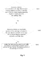
Figure 3 is a schematic flowchart of a light-emission control method for a cartridge chip according to a third embodiment of the disclosure; -
Figure 4 is a schematic flowchart of a light-emission control method for a cartridge chip according to the third embodiment of the disclosure, where a cartridge state is an ink amount; -
Figure 5 is a schematic flowchart of a light-emission control method for a cartridge chip according to the third embodiment of the disclosure, where a cartridge state is an installation position of a cartridge; -
Figure 6 is a schematic diagram of a light-emission control device for a cartridge chip according to a fourth embodiment of the disclosure; and -
Figure 7 is a structural schematic diagram of a cartridge chip according to a fifth embodiment of the disclosure. - To make objective, technical solution and advantages of the disclosure to be clearer, the technical solution according to the embodiment of the disclosure will be described clearly and completely as follows. It is obvious that the described embodiments are only a part of the embodiment according to the disclosure. All the other embodiments obtained by those skilled in the art based on the embodiment in the disclosure without any creative work belong to the protection scope of the disclosure.
- To solve the problem of prompting the cartridge state in a method for light verification in the conventional technology, that is, to avoid a requirement for a cartridge with the ability to frequently receive a control instruction transmitted by the inkjet imaging apparatus, a light-emission control method for a cartridge chip and a light-emission control device for a cartridge chip are provided according to embodiments of the disclosure. In order to implement the light-emission control for the cartridge chip, a new cartridge chip is further provided according to an embodiment of the disclosure. The cartridge chip may be mounted in a cartridge to form a new cartridge. Accordingly, a cartridge is further provided according to an embodiment of the disclosure.
- Firstly, a cartridge chip according to an embodiment of the disclosure is introduced in detail.
-
Figure 1 is a structural schematic diagram of a cartridge chip according to the first embodiment of the disclosure. The cartridge chip according to the first embodiment of the disclosure is explained in detail in conjunction withFigure 1 . As shown inFigure 1 , the cartridge chip includes: aninterface unit 100, astorage unit 200 and afirst control unit 300. Thefirst control unit 300 is connected with theinterface unit 100 and thestorage unit 200, to transmit and control a signal. - The
interface unit 100 is adapted to connect the cartridge chip with an inkjet imaging apparatus. - The
storage unit 200 is adapted to store information on a cartridge state. - The
first control unit 300 is adapted to determine whether it is currently in a stage that the inkjet imaging apparatus prompts the cartridge state, when the inkjet imaging apparatus begins to supply power to the cartridge chip; determine whether a current cartridge state meets a preset condition, in the case that it is currently in the stage that the inkjet imaging apparatus prompts the cartridge state; and control a light-emission unit to emit light according to a preset light-emission rule to prompt a user with the current cartridge state, in the case that the current cartridge state meets the preset condition. - Specifically, in the cartridge chip according to the embodiment of the disclosure, the
interface unit 100 is adapted to connect the cartridge chip with the inkjet imaging apparatus via a signal wire or via a wireless antenna. Only one cartridge chip is shown inFigure 1 . Actually, multiple cartridges may be typically mounted in an inkjet imaging apparatus for imaging a color image, which are mounted in the inkjet imaging apparatus in a detachable way and are connected to the inkjet imaging apparatus via the same communication bus. Theinterface unit 100 may include a filter circuit, a time-delay circuit, a rectification circuit and a reset circuit, to process a received signal. Theinterface unit 100 is adapted to transmit the signal between the cartridge chip and the inkjet imaging apparatus. That is, theinterface unit 100 may receive a signal from the inkjet imaging apparatus, and may also transmit a signal transmitted by the cartridge chip to the inkjet imaging apparatus. - More specifically, the cartridge chip may receive the control instruction transmitted by the inkjet imaging apparatus, via the
interface unit 100. That is, theinterface unit 100 may receive the control instruction transmitted by the inkjet imaging apparatus. Thefirst control unit 300 performs the corresponding operation control in response to the control instruction. It should be noted that the control instruction transmitted by the inkjet imaging apparatus includes a light control instruction and a read/write control instruction. The light control instruction is an instruction for performing a light-emission control to the cartridge by thefirst control unit 300. The read/write control instruction is an instruction for performing a read/write operation on thestorage unit 200 of the cartridge. - In the cartridge chip according to an embodiment of the disclosure, the
storage unit 200 is adapted to store information on the cartridge. More specifically, the information on the cartridge may include information of the cartridge state, such as a manufacturer, production date, the used ink amount and the remaining ink amount. Moreover, cartridge identifying information may be stored in thestorage 200 to distinguish different cartridges. The cartridge identifying information may be ink color information, or may be a device address of the storage unit, or other information capable of distinguishing different types of the cartridges. - Since the ink amount plays an important role in normal operation of the inkjet imaging apparatus, typically at least the information on the ink amount of the cartridge is stored in the
storage unit 200. The state of the ink amount may include: a low ink amount and a sufficient ink amount according to the ink amount. The two states of the low ink amount and the sufficient ink amount may be distinguished by a set threshold. The ink amount is low in the case that information on the ink amount in the storage unit is less than the set threshold; and the ink amount is sufficient in the case that the information on the ink amount in the storage unit is greater than the set threshold. The information on current ink amount may be obtained based on a remaining ink amount, an ink consumption amount or a flag for the ink amount, which are all stored in the storage unit. - Furthermore, the state of the low ink amount may be divided into a basic low ink amount and a serious low ink amount according the ink amount. Specifically, it is assumed that the ink amount is 100% in the case that the cartridge is filled with the ink; the ink amount is the serious low ink amount in the case that the ink amount is less than a first threshold (such as 3%); the ink amount is the basic low ink amount in the case that the ink amount is between the first threshold (such as 3%)and a second threshold (such as 10%); and the ink amount is the sufficient ink amount in the case that the ink amount is greater than the second threshold (such as 10%). It should be noted that the first and second thresholds in an embodiment of the disclosure may be set as any value according to practical application and a condition of the inkjet imaging apparatus, the value of which will not be limited to the above-described example.
- The information on the ink amount stored in the storage unit may be recorded as FF, in the case that the ink amount is the serious low ink amount. The information on the ink amount stored in the storage unit may be recorded as EF, in the case that the ink amount is the basic low ink amount. The information on the ink amount stored in the storage unit may be recorded as EE, in the case that the ink amount is the sufficient ink amount. FF, EF and EE herein are the above-described flags for the ink amount.
- The
storage unit 200 may be a nonvolatile memory, such as EPROM, EEPROM, FLACH, a ferroelectric memory or a phase change memory, which is commonly applied in the conventional technology; or may be a volatile memory in conjunction with a power supply, such as SRAM in conjunction with a battery or a capacitor, DRAM in conjunction with a battery or a capacitor. - The
first control unit 300 is also connected to the light-emission unit 400 to control the light-emission unit 400 to emit light according to a preset light-emission rule. Thefirst control unit 300 and the light-emission unit 400 may be connected via a signal wire or a wireless antenna. - It should be noted that the light-
emission unit 400 may be provided at the cartridge chip, or at the cartridge instead of the cartridge chip. That is, the cartridge chip according to an embodiment of the disclosure may further include the light-emission unit 400. - Furthermore, in order to meet the requirement of promoting users, the light-
emission unit 400 according to an embodiment of the disclosure may be an electric element for emitting visible light, such as a light-emitting diode (LED). Alternatively, fluorescent material may be provided on the cartridge or the cartridge chip. In this case, the light-emission unit 400 may be an emitter for emitting invisible ultraviolet rays. The light-emission unit 400 emits ultraviolet rays to the fluorescent material to prompt the user. - The light-emission control method for the cartridge chip includes as follows.
- The cartridge chip begins to operate when the inkjet imaging apparatus begins to supply power to the cartridge chip. The
interface unit 100 in the cartridge chip connects the cartridge chip with the inkjet imaging apparatus via the signal wire or the wireless antenna. Then, thefirst control unit 300 determines whether it is currently in a stage that the inkjet imaging apparatus prompts the cartridge state. If yes, i.e., currently in a stage that the inkjet imaging apparatus prompts the cartridge state, thefirst control unit 300 determines whether the current cartridge state stored in thestorage unit 200 of the cartridge chip meets a preset condition. Thefirst control unit 300 controls the light-emission unit 400 to emit light according to a preset light-emission rule, in the case that the current cartridge state stored in thestorage unit 200 of the cartridge chip meets the preset condition. - It should be noted that the above-described preset condition may be a condition of a cartridge state abnormal. The light-emission control method for the cartridge chip may be used to prompt the user with the cartridge state abnormal, in the case that the preset condition is the condition of the cartridge state abnormal.
- Whether it is currently in the stage that the inkjet imaging apparatus prompts the cartridge state may be determined based on a type of a received light control instruction or the number of the light control instructions received in a preset period of time.
- In the case that whether it is currently in the stage that the inkjet imaging apparatus prompts the cartridge state is determined based on the type of the received light control instruction, the
first control unit 300 may include a first determination sub-unit. - The first determination sub-unit is adapted to determine whether the type of the light control instruction is a preset type of a light control instruction; and determine that it is currently in the stage that the inkjet imaging apparatus prompts the cartridge state, in the case that the type of the light control instruction is the preset type of the light control instruction.
- It should be noted that there are typically four types of the light control instruction transmitted from the inkjet imaging apparatus to the cartridge, which includes: a light detection switch-on instruction, a light detection switch off instruction, a light prompt switch-on instruction and a light prompt switch-off instruction. It is determined that it is currently in the stage that the inkjet imaging apparatus prompts the cartridge state, when the light control instruction is the light prompt switch-on instruction or the light prompt switch-off instruction. It is determined that it is currently in the stage that the inkjet imaging apparatus detects a position of the cartridge, when the light control instruction is the light detection switch-on instruction or the light detection switch-off instruction. That is, the preset type of the light control instruction may be the light prompt switch-on instruction or the light prompt switch-off instruction.
- Moreover, no light control instruction is transmitted to the cartridge chip by the inkjet imaging apparatus, in a normal operation of the cartridge chip. In this case, it may be determined that it is currently in the stage that the inkjet imaging apparatus prompts the cartridge state. Specifically, the inkjet imaging apparatus does not transmit any light control instruction to the cartridge in a preset period of time (a first preset period of time), that is, the number of the light control instruction received in the first preset period of time is 0, it may be determined that it is currently in the stage that the inkjet imaging apparatus prompts the cartridge state. In the case that whether it is currently in the stage that the inkjet imaging apparatus prompts the cartridge state is determined based on the number of the light control instruction received in the preset period of time, the first control unit may include a first count sub-unit and a first determination sub-unit.
- The first count sub-unit is adapted to count the number of the light control instruction received in the first preset period of time.
- The first determination sub-unit is adapted to determine that it is currently in the stage that the inkjet imaging apparatus prompts the cartridge state, in the case that the number of the light control instruction received in the first preset period of time is 0.
- In the case that the type of the light control instruction transmitted by the inkjet imaging apparatus in the stage that the that the inkjet imaging apparatus detects the position of the cartridge position is the same as that in the stage that the inkjet imaging apparatus prompts the cartridge state, whether it is currently in the stage that the inkjet imaging apparatus prompts the cartridge state can not be determined, based on the above-described type of the light control instruction. In addition, since the inkjet imaging apparatus transmits the light control instruction to the cartridge in different frequencies in different stages, whether it is currently in the stage that the inkjet imaging apparatus prompts the cartridge state may be determined, based on the number of the light control instruction received in the preset period of time.
- In the case that whether it is currently in the stage that the inkjet imaging apparatus prompts the cartridge state is determined based on the number of the light control instructions received in the preset period of time, the first control unit may include a second count sub-unit and a second determination sub-unit.
- The second count sub-unit is adapted to count the number of the light control instruction received in a second preset period of time.
- The second determination sub-unit is adapted to determine that it is currently in the stage that the inkjet imaging apparatus prompts the cartridge state, in the case that the number of the light control instructions received in the second preset period of time exceeds a preset value.
- For example, it is assumed that the preset period of time is 3 seconds. It is determined that it is currently in the stage that the inkjet imaging apparatus prompts the cartridge state, in the case that the number of the light control instructions received in 3 seconds exceeds 5 pieces (the preset value).
- Furthermore, to feedback to the user the information on a good electrical connection between the cartridge chip and the inkjet imaging apparatus in time, after the cartridge is mounted in the inkjet imaging apparatus, the
first control unit 300 begins to control the light-emission unit 400 to emit light continuously when the inkjet imaging apparatus supplies power to the cartridge chip via theinterface unit 100. This case may be defined as the stage that the inkjet imaging apparatus prompts the cartridge state. That is, an initialization state of the cartridge chip may be preset as the stage that the inkjet imaging apparatus prompts the cartridge state. In this way, the first control unit is not necessary to determine whether it is currently in the stage that the inkjet imaging apparatus prompts the cartridge state, based on the light control instruction received by the interface unit, as described in the above method. After receiving the read/write control instruction transmitted by the inkjet imaging apparatus, the cartridge chip is in a read/write stage (neither the stage that the inkjet imaging apparatus prompts the cartridge state, nor the stage that the inkjet imaging apparatus detects the position of the cartridge). In this case, to avoid a random flash of the cartridge chip to cause user misunderstanding, the current stage (the stage that the inkjet imaging apparatus prompts the cartridge state) may be quitted. Likewise, in the case that the initialization state of the cartridge chip is currently in the stage that the inkjet imaging apparatus prompts the cartridge state, the first control unit may determine whether to quit the current stage (the stage that the inkjet imaging apparatus prompts the cartridge state), based on whether the interface unit has received the light detection switch-on instruction or the light detection switch-off instruction. - From the above-described methods for determining whether it is currently in the stage that the inkjet imaging apparatus prompts the cartridge state, it is summarized that whether it is currently in the stage that the inkjet imaging apparatus prompts the cartridge state is determined by determining the type of the control instruction and/or the number of the light control instruction received in the preset period of time, in the embodiment of the disclosure. Specifically, the number of the light control instructions received in the preset period of time includes two cases: the number of the light control instructions received in the first preset period of time is zero; and the number of the light control instructions received in the second preset period of time exceeds the preset value. The first preset period of time and the second preset period of time may be the same, or different. The process of determining whether it is currently in the stage that the inkjet imaging apparatus prompts the cartridge state is performed when the inkjet imaging apparatus begins to supply power to the cartridge chip.
- As mentioned above, the cartridge state at least includes the state of the ink amount. In this case, the first control unit adapted to determine whether the current cartridge state meets the preset condition may further adapted to determine whether the current ink amount of the cartridge meets the condition of the low ink amount.
- In the case that the current ink amount of the cartridge meets the condition of the low ink amount, the
first control unit 300 controls the light-emission unit 400 to emit light according to the preset light-emission rule, to prompt the user that the cartridge is currently in the state of the low ink amount. The preset light-emission rule may be flashed fast. The light-emission unit 400 keeps emitting light continuously if the ink amount is sufficient. The preset light-emission rule may be to stop light-emission and keep a switching-off state. - It may also be set that the light-emission unit emits light in a light-emission control rule (such as lighting steady) in the case of the sufficient ink amount; and the light-emission unit emits light in another light-emission control rule (such as forbidding to emit light) in the case of the low ink amount.
- To further make the user know the amount of ink, the light-emission unit may emit light according to different light-emission rules in the case of the sufficient ink amount, the basic low ink amount, or the serious low ink amount. For example, the light-emission unit keeps emitting light continuously, in the case of the sufficient ink amount. The first control unit drives the light-emission unit to emit light in a first driving frequency according to a light-emission rule that the switch-on and the switch-off are performed alternately, in the case of the basic low ink amount. The first control unit drives the light-emission unit to emit light in a second driving frequency according to a light-emission rule that the switch-on and the switch-off are performed alternately, in the case of the serious low ink amount. The first driving frequency is different from the second driving frequency, and the first driving frequency is lower than the second driving frequency. For example, the light-emission unit alternately switches on or off at an interval of 1 second, i.e., in the first driving frequency. Thus, the user may see that the light-emission unit flashes in a low speed, to prompt the user to prepare a new cartridge for the replacement. The light-emission unit alternately switches on or off at an interval of 0.5 seconds, i.e., in the second driving frequency. Thus, the user may see that the light-emission unit flashes at a fast speed, to prompt the user to replace the cartridge immediately.
- It is easy to understand that the cartridge state in the storage unit of the cartridge chip according to the first embodiment of the disclosure may further store information for determining an inversion of the cartridge. In this case, the
first control unit 300 adapted to determine whether the current cartridge state meets the preset condition, may further be adapted to determine whether a cartridge, the storage unit of which stores the information for determining the inversion of the cartridge, is inverted. The first control unit controls the light-emission unit to emit light according to the preset light-emission rule to prompt the user that the information for determining the inversion of the cartridge stored in the storage unit of this cartridge indicates that the cartridge is inverted. - It can be known from the above description that, the cartridge chip according to the embodiment of the disclosure may transmit the prompt information of the low ink amount to the user, and may also transmit information of the inverted position of the cartridge to the user. Actually, the cartridge chip according to the embodiment of the disclosure may be used to transmit the prompt information of the abnormal cartridge state to the user.
- In order to prompt the user with the abnormal cartridge state, the light control instruction transmitted from the inkjet imaging apparatus to the cartridge chip may include the light switch-off instruction. Thus, the cartridge in an abnormal state may flash, to prompt the user.
- In the case that the cartridge chip according to the above-described embodiment is applied to prompt the user with the cartridge state, the
first control unit 300 of the cartridge chip may determine autonomously whether it is currently in the stage that the inkjet imaging apparatus prompts the cartridge state, based on the type of the light control instruction or the number of the light control instructions; then determine whether the cartridge state stored in the storage unit of the cartridge chip is abnormal; and control the light-emission unit to prompt the user based on the preset light-emission rule, thereby achieving the objective of prompting the user with the cartridge state. The process of determining whether it is currently in the stage that the inkjet imaging apparatus prompts the cartridge state is performed, when the inkjet imaging apparatus begins to supply power to the cartridge chip. In the above method for prompting the cartridge state, it is not necessary to perform repeatedly a light verification process between the inkjet imaging apparatus and the cartridge chip. Therefore, the cartridge is not required to have the ability to receive frequently the light control instruction transmitted by the inkjet imaging apparatus. Hence, the process requirement and design difficulty for the cartridge according to the embodiment of the disclosure are low, and the manufacturing costs are reduced. - As mentioned above, if the initialization state of the cartridge chip is currently in the stage that the inkjet imaging apparatus prompts the cartridge state, the first control unit may determine whether the current cartridge state meets the preset condition, when the inkjet imaging apparatus or other power sourcing apparatus begins to supply power to the cartridge chip. The light-emission unit is controlled to emit light according to the preset light-emission rule to prompt the user with the current cartridge state, in the case that the current cartridge state meets the preset condition. Thus, with the cartridge chip according to the disclosure, the user may know the cartridge state easily and quickly by several simple power sourcing apparatus supplying power to the cartridge chip in the cartridge; rather than mounting the cartridge in the inkjet imaging apparatus, transmitting the light control instruction from the inkjet imaging apparatus to the cartridge chip, and obtaining the current cartridge state.
- Furthermore, in the first embodiment, the
first control unit 300 may be adapted to perform a read/write operation on thestorage unit 200 in response to a read/write control instruction transmitted by the inkjet imaging apparatus and received by theinterface unit 100. Thefirst control unit 300 can perform a control operation on the light control instruction and the read/write control instruction. That is, the units which have two functions are integrated to form thefirst control unit 300 in the first embodiment. Actually, a unit for performing the control operation on the light control instruction and a unit for performing the control operation on the read/write control instruction may be implemented by two separate units, the details of which refers to the second embodiment. - The cartridge chip according to the second embodiment is similar as the cartridge chip according to the first embodiment. For simplicity, this embodiment emphasizes the difference therebetween, and the same aspect is referred to the description of the first embodiment.
- As shown in
Figure 2 , the above-described cartridge chip may further include asecond control unit 500 which is connected to theinterface unit 100 and thestorage unit 200. Thesecond control unit 500 is adapted to perform a read/write operation on the storage unit, in response to the read/write control instruction transmitted by the inkjet imaging apparatus and received by theinterface unit 100. In this embodiment, the first control unit 300' merely functions as the control operation on the light control instruction, rather than the read/write control instruction. Thesecond control unit 500 is adapted to perform the control operation on the read/write control instruction. - Based on the cartridge chip according to the above-described first or second embodiment, a new cartridge is further provided according to an embodiment of the disclosure. The cartridge includes the cartridge chip, which is any one of the cartridge chips in the above-described first embodiment or the second embodiment. The cartridge according to the embodiment of the disclosure may be adapted to fill colorant for inkjet imaging, where the colorant may be toner, dye ink or pigment ink. The cartridge may be a toner cartridge, an ink cartridge, a selenium drum or a drum unit.
- Based on the cartridge and the cartridge chip according the above-described embodiment, a light-emission control method for the cartridge chip is also provided according to an embodiment of the disclosure, the details of which refers to the third embodiment.
- As shown in
Figure 3 , a light-emission control method for a cartridge chip includes steps S301 to S303. - Step S301 includes: determining whether it is currently in a stage that the inkjet imaging apparatus prompts the cartridge state, when the inkjet imaging apparatus begins to supply power to the cartridge chip.
- As described in the first or second embodiment, the cartridge chip according to the embodiment of the disclosure includes an
interface unit 100, astorage unit 200 and afirst control unit 300. - As described in the first embodiment, there are multiple ways by which the
first control unit 300 determines whether it is currently in the stage that the inkjet imaging apparatus prompts the cartridge state. The ways are as follows. - In a first way, it is determined whether a type of the light control instruction is a preset type of the light control instruction.
- Firstly, the
interface unit 100 receives the light control instruction transmitted by the inkjet imaging apparatus. - Then, it is determined whether the type of the light control instruction is the preset type of the light control instruction, and it is determined that it is currently in the stage that the inkjet imaging apparatus prompts the cartridge state, in the case that the type of the light control instruction is the preset type of the light control instruction.
- Typically, there are four types of the light control instruction transmitted from the inkjet imaging apparatus to the cartridge, which includes: a light detection switch-on instruction, a light detection switch-off instruction, a light prompt switch-on instruction and a light prompt switch-off instruction. It is determined that it is currently in the stage that the inkjet imaging apparatus prompts the cartridge state, when the light control instruction is the light prompt switch-on instruction or the light prompt switch-off instruction. It is determined that it is currently in the stage that the inkjet imaging apparatus detects a position of the cartridge, when the light control instruction is the light detection switch-on instruction or the light detection switch-off instruction. That is, the preset type of the light control instruction may be the light prompt switch-on instruction or the light prompt switch-off instruction.
- In the case that the type of the light control instruction transmitted by the inkjet imaging apparatus in the stage that the that the inkjet imaging apparatus detects the position of the cartridge position is the same as that in the stage that the inkjet imaging apparatus prompts the cartridge state, whether it is currently in the stage that the inkjet imaging apparatus prompts the cartridge state can not be determined based on the above-described type of the light control instruction. In addition, since the inkjet imaging apparatus transmits the light control instruction to the cartridge in different frequencies in different stages, whether it is currently in the stage that the inkjet imaging apparatus prompts the cartridge state may be determined, based on the number of the light control instruction received in the preset period of time.
- In a second way, it is determined whether the number of the light control instructions received in a preset period of time exceeds a preset value.
- Specifically, the determining method includes:
- firstly, receiving the light control instruction transmitted by the inkjet imaging apparatus; and
- then, counting the number of the light control instructions received in a preset period of time (a second preset period of time); and determining it is currently in the stage that the inkjet imaging apparatus prompts the cartridge state, in the case that the number of the light control instructions received in the preset period of time (the second preset period of time) exceeds a preset value.
- For example, it is assumed that the preset period of time is 3 seconds. It is determined that it is currently in the stage that the inkjet imaging apparatus prompts the cartridge state, in the case that the number of the light control instructions received in 3 seconds exceeds 5 pieces (the preset value).
- Moreover, the inkjet imaging apparatus does not transmit any light control instruction to the cartridge chip in a normal operation of the cartridge chip. In this case, it may be determined that it is currently in the stage that the inkjet imaging apparatus prompts the cartridge state. Specifically, when the inkjet imaging apparatus does not transmit any light control instruction to the cartridge chip in a preset period of time (a first preset period of time), that is, the number of the light control instructions received in the first preset period of time is 0, it may be determined that it is currently in the stage that the inkjet imaging apparatus prompts the cartridge state.
- Furthermore, to feedback to the user the information on a good electrical connection between the cartridge chip and the inkjet imaging apparatus in time, after the cartridge is mounted in the inkjet imaging apparatus, the
first control unit 300 begins to control the light-emission unit 400 to emit light continuously when the inkjet imaging apparatus supplies power to the cartridge chip via the interface unit. This case may be defined as the stage that the inkjet imaging apparatus prompts the cartridge state. That is, an initialization state of the cartridge chip may be preset as the stage that the inkjet imaging apparatus prompts the cartridge state. In this way, in this method, it is not necessary to determine whether it is currently in the stage that the inkjet imaging apparatus prompts the cartridge state, based on the received light control instruction, as described in the above method. After receiving the read/write control instruction transmitted by the inkjet imaging apparatus, the cartridge chip is in a read/write stage (neither the stage that the inkjet imaging apparatus prompts the cartridge state, nor the stage that the inkjet imaging apparatus detects the position of the cartridge). In this case, to avoid a random flashing of the cartridge chip to cause the user misunderstanding, the current stage (the stage that the inkjet imaging apparatus prompts the cartridge state) may be quitted. Likewise, in the case that the initialization state of the cartridge chip is currently in the stage that the inkjet imaging apparatus prompts the cartridge state, in this method, it may be determined whether to quit the current stage (the stage that the inkjet imaging apparatus prompts the cartridge state) based on the reception of the light detection switch-on instruction or the light detection switch-off instruction. - From the above-described methods for determining whether it is currently in the stage that the inkjet imaging apparatus prompts the cartridge state, it is summarized that, this determination is performed based on the type of the control instruction or the number of the light control instructions received in the preset period of time. Specifically, the number of the light control instructions received in the preset period of time includes two cases: the number of the light control instructions received in the first preset period of time is zero; and the number of the light control instructions received in the second preset period of time exceeds the preset value. The first preset period of time and the second preset period of time may be the same, or different. The process of determining whether it is currently in the stage that the inkjet imaging apparatus prompts the cartridge state is performed when the inkjet imaging apparatus begins to supply power to the cartridge chip.
- It should be noted that, in the light-emission control method for the cartridge chip according to the embodiment of the disclosure, whether it is currently in the stage that the inkjet imaging apparatus prompts the cartridge state is determined when the inkjet imaging apparatus begins to supply power to the cartridge chip. Therefore, according to the light-emission control method for the cartridge chip according to the embodiment of the disclosure, the light verification process is avoided, the light-emission control is not necessary to be controlled by the inkjet imaging apparatus, and the cartridge chip may control the light-emission autonomously. Hence, design and production process for the cartridge chip is simplified, and costs of the apparatus are reduced according to the light-emission control method.
- Step S302 includes: determining whether current cartridge state meets a preset condition, in the case that it is currently in the stage that the inkjet imaging apparatus prompts the cartridge state.
- After it is determined that it is currently in the stage that the inkjet imaging apparatus prompts the cartridge state, the first control unit in the cartridge chip determines whether the current cartridge state stored in the storage unit meets the preset condition; and step S303 is performed, if the current cartridge state meets the preset condition.
- It should be noted that the preset condition may be a condition of an abnormal cartridge state, such as a condition of the low ink amount, or a condition of the inverted cartridge.
- Step S303 includes: controlling the light-emission unit to emit light according to a preset light-emission rule to prompt the user with the current cartridge state.
- The first control unit controls the light-emission unit to emit light according to the preset light-emission rule to prompt the user with the current cartridge state.
- The light-emission control method for the cartridge chip according to the third embodiment is provided above. With the light-emission control method, the light-emission is controlled according to the determined results of the two determining steps when the inkjet imaging apparatus or other power supply apparatus supplies power to the cartridge chip. The light-emission control is not necessary to consist with the control of the inkjet imaging apparatus. Hence, it is easy to prompt the user with the cartridge state in the light-emission control method for the cartridge chip, thus it is beneficial to reduce process requirement and design difficulty for the cartridge chip.
- To understand clearly the light-emission control method for the cartridge chip according to the embodiment of the disclosure, it is taken the cartridge states including an ink amount and a position of a cartridge as an example to explain as follows.
- In the case that the cartridge state refers to the ink amount, a light-emission control method for a cartridge chip include steps S401 to S403, as shown in
Figure 4 . - Step S401 includes: determining whether it is currently in the stage that the inkjet imaging apparatus prompts the cartridge state, when the inkjet imaging apparatus begins to supply power to the cartridge chip.
- This step is the same as the step S301. The detailed description refers to the description of the step S301 to simplify.
- Step S402 includes: determining whether the current ink amount of the cartridge meets a condition of a low ink amount, in the case that it is currently in the stage that the inkjet imaging apparatus prompts the cartridge state.
- The low ink amount and the sufficient ink amount may be determined according to a preset threshold. Specifically, the
first control unit 300 determines whether the information of the ink amount stored in the storage unit is greater than the preset threshold. If the information of the ink amount stored in the storage unit is greater than the preset threshold, the ink amount is sufficient and the condition of the low ink amount is not met; else, the ink amount is low, the condition of the ink amount is met, and then step S403 is performed. - To more clearly prompt the user with the state of the ink amount, the state of the low ink amount may be further divided into a basic low ink amount and a serious low ink amount. Similarly, the basic low ink amount and the serious low ink amount are distinguished by a preset threshold. The serious low ink amount is determined, in the case that the information of the ink amount in the storage unit is less than a first threshold. The basic low ink amount is determined, in the case that the information of the ink amount in the storage unit ranges from the first threshold to a second threshold. The sufficient ink amount is determined, in the case that the information of the ink amount in the storage unit is greater than the second threshold.
- Step S403 includes: controlling the light-emission unit to emit light according to a preset light-emission rule to prompt the user with the current ink amount of the cartridge.
- Specifically, the first control unit may control the light-emission unit to emit light based on one light-emission rule, in the case of the sufficient ink amount; and the first control unit may control the light-emission unit to emit light based on another light-emission rule to prompt the user that the current ink amount is insufficient, in the case of the low ink amount.
- Furthermore, the state of the low ink amount may be further divided into a basic low ink amount and a serious low ink amount. To prompt the user more clearly, the two states may correspond to two different light-emission rules. Specifically, the first control unit controls the light-emission unit to emit light based on a light-emission rule that the light-emission unit is switched on and off alternatively in a first driving frequency, in the case of the basic low ink amount. The first control unit controls the light-emission unit to emit light based on a light-emission rule that the light-emission unit is switched on and off alternatively in a second driving frequency, in the case of the serious low ink amount. The first driving frequency is lower than the second driving frequency. Therefore, a flash frequency of the light-emission in the case of the basic low ink amount is lower than a flash frequency of the light-emission in the case of the serious low ink amount. Thus, the user is prompted with the current ink amount of the cartridge to replace the cartridge or add ink in time.
- In the case that the cartridge state refers to the position of the cartridge, the light-emission control method for the cartridge chip includes steps S501 to S503, as shown in
Figure 5 . - Step S501 includes: determining whether it is currently in the stage that the inkjet imaging apparatus prompts the cartridge state, when the inkjet imaging apparatus begins to supply power to the cartridge chip.
- This step is the same as the step S301. The detailed description refers to the description of the step S301 to simplify.
- Step S502 includes: determining whether the installation position of the cartridge is inverted, in the case that it is currently in the stage that the inkjet imaging apparatus prompts the cartridge state.
- It should be noted that the storage unit of the cartridge chip may store position information of the cartridge, such as the information for determining an inversion of the installation position. The position information may be written into the cartridge chip by the inkjet imaging apparatus, after the stage that the inkjet imaging apparatus detects the cartridge position. The first control unit determines whether the installation position of the cartridge stored in the storage unit of the cartridge chip is inverted. Step S503 is performed, if the installation position of the cartridge is inverted.
- Step S503 includes: controlling the light-emission unit to emit light according to a preset light-emission rule to prompt the user that the cartridge position is inverted.
- Based on the above-described light-emission control method for the cartridge chip, a light-emission control device for a cartridge chip is further provided according to an embodiment of the disclosure. The details are referred to a fourth embodiment.
- As shown in
Figure 6 , the light-emission control device for the cartridge chip according to the fourth embodiment of the disclosure includes afirst determination unit 61 and asecond determination unit 62. - The
first determination unit 61 is adapted to determine whether it is currently in a stage that an inkjet imaging apparatus prompts a cartridge state, when the inkjet imaging apparatus begins to supply power to the cartridge chip. - The
second determination unit 62 is adapted to determine whether a current cartridge state meets a preset condition in the case that it is currently in the stage that the inkjet imaging apparatus prompts the cartridge state, wherein light is emitted according to a preset light-emission rule to prompt a user with the current cartridge state in the case that the current cartridge state meets the preset condition. - The light-emission control device for the cartridge chip according to the embodiment of the disclosure controls the light-emission according to the determined results of the two determining steps, when the inkjet imaging apparatus supplies power to the cartridge chip. The light-emission control is not necessary to consists with the control of the inkjet imaging apparatus. Hence, the light-emission control device for the cartridge chip may be easy to prompt the user with the cartridge state, thus it is beneficial to reduce process requirement and design difficulty for the cartridge chip.
- The above determining whether it is currently in the stage that the inkjet imaging apparatus prompts the cartridge state includes: determining whether it is currently in the stage that the inkjet imaging apparatus prompts the cartridge state based on a type of the light control instruction or the number of the light control instructions received in a preset period of time.
- The cartridge chip according to the first embodiment of the disclosure determines whether it is currently in the stage that the inkjet imaging apparatus prompts the cartridge state based on the type of the received light control instruction or the number of the light control instruction received in the preset period of time. In another embodiment of the disclosure, it may be determined whether it is currently in the stage that the inkjet imaging apparatus prompts the cartridge state based on the number of the light control instructions received in the preset period of time and a specific light control instruction included in the received light control instruction. The details are referred to the fifth embodiment.
- The cartridge chip according to the fifth embodiment is similar as that according to the first and second embodiment. This embodiment emphasizes the difference therebetween for simplicity.
- As shown in
Figure 7 , similarly as in the first embodiment, the cartridge chip according to the fifth embodiment includes the interface unit 100', the storage unit 200' and thefirst control unit 300". Thefirst control unit 300" is connected to the interface unit 100' and the storage unit 200', to transmit the signal and perform the control. The first control unit may further be connected to a light-emission unit 400', and the light-emission unit 400' may be provided at the cartridge chip or at the cartridge. - It should be noted that at least the cartridge identifying information is stored in the storage unit 200' to distinguish different cartridges according to the embodiment. In particular, the cartridge identifying information may be the information of the ink color, a device address of the storage unit, or other information for distinguishing different types of the cartridge.
- In this embodiment, the
first control unit 300" determines whether it is currently in the stage that the inkjet imaging apparatus prompts the cartridge state, based on the number of the light control instructions received in the preset period of time and the specific light control instruction included in the received light control instruction. - Specifically, the number of the light control instructions received by the interface unit 100' in the preset period of time is counted. It is preliminarily determined that it is currently in the stage that the inkjet imaging apparatus prompts the cartridge state, in the case that the number of the light control instructions exceeds a preset value. When the received light control instruction includes the specific light control instruction, it is determined whether the cartridge identifying information carried in the specific light control instruction is associated with the cartridge identifying information stored in the storage unit of the cartridge chip. If yes, it is determined that it is currently in the stage that the inkjet imaging apparatus prompts the abnormal cartridge state, and the first control unit controls the light-emission unit to emit light according to the preset light-emission rule, to prompt the user that it is currently in the stage that the inkjet imaging apparatus prompts the abnormal cartridge state.
- It should be noted that the "associated" according to the embodiment may be considered that the cartridge identifying information carried in the specific light control instruction is the same as the cartridge identifying information stored in the storage unit of the cartridge chip; or may be considered that the cartridge identifying information carried in the specific light control instruction corresponds to the cartridge identifying information stored in the storage unit of the cartridge chip. The two corresponding cartridge identifying information indicates the same cartridge.
- To better prompt the user that it is currently in the stage that the inkjet imaging apparatus prompts the abnormal cartridge state, the specific light control instruction is the light switch-off instruction. Thus, the light-emission unit may flash to attract the attention of the user.
- To understand the embodiment of the disclosure clearly, it is explained by example below. For example, it is assumed that the preset period of time is 3 seconds. It is determined preliminarily that it is currently in the stage that the inkjet imaging apparatus prompts the cartridge state, in the case that the number of the light control instruction received in 3 seconds exceeds 5 pieces. The cartridge chip storing identifying information of a yellow cartridge is determined in the stage that the inkjet imaging apparatus prompts the yellow cartridge abnormal, in the case that the received light control instruction includes the light switch-off instruction, and the light switch-off instruction includes such as the identifying information of the yellow cartridge.
- It is easy to understand that the above-described specific light control instruction may be other light control instructions in addition to the light switch-off instruction.
- It should be noted the cartridge chip according to the fifth embodiment controls the light-emission unit to emit light to prompt the user, once it is determined that it is currently in the stage that the inkjet imaging apparatus prompts the cartridge state; rather than control the light-emission unit to emit light after it is determined whether the current cartridge state meets the preset condition. Hence, another cartridge chip for performing a light-emission control is provided according to the fifth embodiment of the disclosure.
- It should be understood that, although the present specification is described according to the embodiments, but not each embodiment only contains an independent technical solution. This narrative mode of the specification is just for clarity. Those skilled in the art should treat the specification as a whole, and the technical solution in each embodiment may be appropriately combined to form other embodiment which can be understood by the skilled in the art.
- The series of detailed explanation listed above are merely a concrete description for feasible embodiment of the disclosure, which are not intended to limit the protection scope of the disclosure. Any equivalent embodiment or change without departing from the technology and the spirit of the disclosure should be contained within the protection scope of the disclosure.
Claims (15)
- A light-emission control method for a cartridge chip, the method comprising:determining whether it is currently in a stage that an inkjet imaging apparatus prompts a cartridge state, when the inkjet imaging apparatus begins to supply power to the cartridge chip; anddetermining whether a current cartridge state meets a preset condition, in a case that it is currently in the stage that the inkjet imaging apparatus prompts the cartridge state; and emitting light according to a preset light-emission rule to prompt a user with the current cartridge state, in a case that the current cartridge state meets the preset condition.
- A method according to claim 1, wherein the determining whether it is currently in a stage that an inkjet imaging apparatus prompts a cartridge state comprises: determining whether it is currently in the stage that the inkjet imaging apparatus prompts the cartridge state, based on a type of a received light control instruction or the number of the light control instructions received in a preset period of time.
- A method according to claim 2, wherein determining whether it is currently in the stage that the inkjet imaging apparatus prompts the cartridge state, based on a type of a received light control instruction, comprises:receiving the light control instruction transmitted by the inkjet imaging apparatus; anddetermining whether the type of the light control instruction is a preset type of the light control instruction; and determining that it is currently in the stage that the inkjet imaging apparatus prompts the cartridge state, in a case that the type of the light control instruction is the preset type of the light control instruction.
- A method according to any one of claims 1 to 3, wherein the cartridge state comprises an ink amount, and the determining whether a current cartridge state meets a preset condition; and emitting light according to a preset light-emission rule to prompt a user with the current cartridge state, in a case that the current cartridge state meets the preset condition, comprises:determining whether a current ink amount of the cartridge meets a condition of a low ink amount; and emitting light according to the preset light-emission rule to prompt the user with the low ink amount, in a case that current ink amount of the cartridge meets the condition of the low ink amount.
- A method according to claim 4, wherein whether the current ink amount of the cartridge meets the condition of the low ink amount is determined based on a remaining ink amount, an ink consumption amount or a flag for the ink amount.
- A method according to any one of claims 1 to 3, further comprising: receiving a read/write control instruction transmitted by the inkjet imaging apparatus; and
quitting the stage that the inkjet imaging apparatus prompts the cartridge state, in response to the received read/write control instruction transmitted by the inkjet imaging apparatus, in the case that it is currently in the stage that the inkjet imaging apparatus prompts the cartridge state. - A light-emission control device for a cartridge chip, comprising:a first determination unit adapted to determine whether it is currently in a stage that an inkjet imaging apparatus prompts a cartridge state, when the inkjet imaging apparatus begins to supply power to the cartridge chip; anda second determination unit adapted to determine whether a current cartridge state meets a preset condition, in a case that it is currently in the stage that the inkjet imaging apparatus prompts the cartridge state, wherein light is emitted according to a preset light-emission rule to prompt a user with the current cartridge state in a case that the current cartridge state meets the preset condition.
- A cartridge chip, comprising: an interface unit, a storage unit and a first control unit, wherein the first control unit is connected with the interface unit and the storage unit;
the interface unit is adapted to connect the cartridge chip with an inkjet imaging apparatus;
the storage unit is adapted to store information on a cartridge state; and
the first control unit is adapted to determine whether it is currently in a stage that an inkjet imaging apparatus prompts a cartridge state, when the inkjet imaging apparatus begins to supply power to the cartridge chip; determine whether a current cartridge state meets a preset condition, in a case that it is currently in the stage that the inkjet imaging apparatus prompts the cartridge state; and control a light-emission unit to emit light according to a preset light-emission rule to prompt a user with the current cartridge state, in the case that the current cartridge state meets the preset condition. - A cartridge chip according to claim 8, further comprising a second control unit adapted to perform a read/write operation on the storage unit in response to a received read/write control instruction.
- A cartridge chip according to claim 8 or 9, further comprising the light-emission unit adapted to emit light according to the preset light-emission rule, to prompt the user with the current cartridge state.
- A cartridge chip according to claim 8 or 9, wherein the interface unit is adapted to receive a light control instruction transmitted by the inkjet imaging apparatus, and the first control unit comprises:a first determination sub-unit adapted to determine whether a type of the light control instruction is a preset type of the light control instruction; determine that it is currently in the stage that the inkjet imaging apparatus prompts the cartridge state, in a case that the type of the light control instruction is the preset type of the light control instruction.
- A cartridge chip according to claim 8 or 9, wherein the interface unit is adapted to receive the light control instruction transmitted by the inkjet imaging apparatus, and the first control unit comprises:a first count sub-unit adapted to count the number of the light control instructions received in a first preset period of time; anda first determination sub-unit adapted to determine that it is currently in the stage that the inkjet imaging apparatus prompts the cartridge state, in a case that the number of the light control instructions received in the first preset period of time is 0;or,a second count sub-unit adapted to count the number of the light control instructions received in a second preset period of time; anda second determination sub-unit adapted to determine that it is currently in the stage that the inkjet imaging apparatus prompts the cartridge state, in a case that the number of the light control instructions received in a second preset period of time exceeds a preset value.
- A cartridge chip according to claim 8 or 9, wherein the cartridge state comprises the ink amount, and the first control unit is further adapted to
determine whether a current ink amount of the cartridge meets a condition of a low ink amount; and emit the light according to the preset light-emission rule to prompt the user with the low ink amount, in a case that the current ink amount of the cartridge meets the condition of the low ink amount. - A cartridge chip according to claim 13, wherein the low ink amount comprises: a basic low ink amount, and a serious low ink amount;
the basic low ink amount indicates that the ink amount ranges from a first threshold to a second threshold; and the light is emitted according to the light-emission rule that the light-emission unit is switched on and off alternately in a first driving frequency; and
the serious low ink amount indicates that the ink amount is less than the first threshold, and the light is emitted according to the light-emission rule that the light-emission unit is switched on and off alternately in a second driving frequency, wherein the first driving frequency is lower than the second driving frequency. - A cartridge comprising a cartridge chip according to any one of claims 8 to 14.
Applications Claiming Priority (2)
| Application Number | Priority Date | Filing Date | Title |
|---|---|---|---|
| CN201310700877 | 2013-12-19 | ||
| CN201410070295.XA CN103818121B (en) | 2013-12-19 | 2014-02-27 | Ink box, ink box chip and light-emitting control method and device of ink box chip |
Publications (3)
| Publication Number | Publication Date |
|---|---|
| EP2886352A2 true EP2886352A2 (en) | 2015-06-24 |
| EP2886352A3 EP2886352A3 (en) | 2016-12-28 |
| EP2886352B1 EP2886352B1 (en) | 2018-06-27 |
Family
ID=50753533
Family Applications (1)
| Application Number | Title | Priority Date | Filing Date |
|---|---|---|---|
| EP14198270.2A Active EP2886352B1 (en) | 2013-12-19 | 2014-12-16 | Cartridge, cartridge chip, light-emission control method and device for cartridge chip |
Country Status (2)
| Country | Link |
|---|---|
| EP (1) | EP2886352B1 (en) |
| CN (1) | CN103818121B (en) |
Cited By (2)
| Publication number | Priority date | Publication date | Assignee | Title |
|---|---|---|---|---|
| CN110134046A (en) * | 2019-05-15 | 2019-08-16 | 杭州旗捷科技有限公司 | A kind of consumable chip, consumable chip dynamic power consumption method of adjustment |
| WO2020136985A1 (en) * | 2018-12-27 | 2020-07-02 | ホリゾン・インターナショナル株式会社 | Bookbinding processing system |
Families Citing this family (4)
| Publication number | Priority date | Publication date | Assignee | Title |
|---|---|---|---|---|
| WO2016192486A1 (en) * | 2015-06-04 | 2016-12-08 | 珠海纳思达企业管理有限公司 | Imaging cartridge and storage chip applied in imaging cartridge |
| CN106183423B (en) * | 2015-02-12 | 2018-05-08 | 珠海纳思达企业管理有限公司 | The storage chip of imaging cartridge and use on imaging cartridge |
| CN110027324A (en) * | 2019-05-06 | 2019-07-19 | 珠海艾派克微电子有限公司 | Nozzle print cartridge, inkjet component and circuit substrate |
| CN111016465B (en) * | 2019-12-24 | 2021-09-07 | 珠海艾派克微电子有限公司 | Chip and imaging box |
Family Cites Families (10)
| Publication number | Priority date | Publication date | Assignee | Title |
|---|---|---|---|---|
| JP5560659B2 (en) * | 2009-10-28 | 2014-07-30 | セイコーエプソン株式会社 | Printing device |
| CN202106686U (en) * | 2011-06-20 | 2012-01-11 | 珠海艾派克微电子有限公司 | Imaging box chip and imaging box |
| CN103129151A (en) * | 2011-11-30 | 2013-06-05 | 珠海天威技术开发有限公司 | Storage chip, data communication method thereof, consumable container and imaging equipment thereof |
| CN105082773B (en) * | 2011-12-30 | 2017-07-21 | 珠海艾派克微电子有限公司 | A kind of storage chip on the print cartridge being removably mounted on printer and print cartridge |
| CN102950901B (en) * | 2011-12-30 | 2015-06-03 | 珠海纳思达企业管理有限公司 | Inkjet cartridge group and method for detecting installed inkjet cartridge group |
| CN103240999B (en) * | 2012-02-10 | 2016-06-08 | 珠海天威技术开发有限公司 | Storage chip and repositioning method, consumable container, imaging device |
| CN202782181U (en) * | 2012-07-10 | 2013-03-13 | 海的集成电路开发(深圳)有限公司 | Ink cartridge chip and ink cartridge |
| CN103832077B (en) * | 2012-11-22 | 2016-02-03 | 珠海艾派克微电子有限公司 | The control method of ink box chip, ink box chip and print cartridge |
| CN103085495B (en) * | 2013-02-26 | 2015-01-14 | 珠海天威技术开发有限公司 | Ink box chip, light emitting display method thereof and ink box |
| CN103241004B (en) * | 2013-05-15 | 2015-02-25 | 珠海天威技术开发有限公司 | Ink box chip and light emitting display method thereof as well as ink box |
-
2014
- 2014-02-27 CN CN201410070295.XA patent/CN103818121B/en active Active
- 2014-12-16 EP EP14198270.2A patent/EP2886352B1/en active Active
Non-Patent Citations (1)
| Title |
|---|
| None |
Cited By (6)
| Publication number | Priority date | Publication date | Assignee | Title |
|---|---|---|---|---|
| WO2020136985A1 (en) * | 2018-12-27 | 2020-07-02 | ホリゾン・インターナショナル株式会社 | Bookbinding processing system |
| JPWO2020136985A1 (en) * | 2018-12-27 | 2021-11-18 | ホリゾン・インターナショナル株式会社 | Bookbinding processing system |
| EP3904113A4 (en) * | 2018-12-27 | 2022-09-28 | Horizon International Inc. | Bookbinding processing system |
| US11718120B2 (en) | 2018-12-27 | 2023-08-08 | Horizon International, Inc. | Binding processing system |
| CN110134046A (en) * | 2019-05-15 | 2019-08-16 | 杭州旗捷科技有限公司 | A kind of consumable chip, consumable chip dynamic power consumption method of adjustment |
| CN110134046B (en) * | 2019-05-15 | 2021-07-23 | 杭州旗捷科技有限公司 | Consumable chip and dynamic power consumption adjusting method of consumable chip |
Also Published As
| Publication number | Publication date |
|---|---|
| EP2886352A3 (en) | 2016-12-28 |
| EP2886352B1 (en) | 2018-06-27 |
| CN103818121B (en) | 2017-01-25 |
| CN103818121A (en) | 2014-05-28 |
Similar Documents
| Publication | Publication Date | Title |
|---|---|---|
| EP2886352A2 (en) | Cartridge, cartridge chip, light-emission control method and device for cartridge chip | |
| CN109419035B (en) | Electronic cigarette and method for adjusting power of electronic cigarette | |
| US11265997B2 (en) | Lighting device for powering from a main power supply and an auxiliary power supply | |
| US9108419B2 (en) | Method for controlling ink cartridge chip, ink cartridge chip and ink cartridge | |
| US8669713B2 (en) | Method for setting and adjusting light emitted from an adjustable lighting device, adjustable lighting device and light-adjusting circuit thereof | |
| CN203004519U (en) | Control unit of light emitting control of ink box, circuit board, ink box and imaging device | |
| US8531114B2 (en) | Illumination beacon | |
| US11602030B2 (en) | Luminaire with power failure detection | |
| CN203004526U (en) | Print cartridge control unit, circuit board, print cartridge and imaging device | |
| CN103085495B (en) | Ink box chip, light emitting display method thereof and ink box | |
| CN103241004B (en) | Ink box chip and light emitting display method thereof as well as ink box | |
| JP2016524557A (en) | Inkjet image forming apparatus and light detection method | |
| CN203004527U (en) | Print cartridge control unit, circuit board, print cartridge and imaging device | |
| CN103465632B (en) | Ink box chip, ink box and ink box adaptive support | |
| CN103786442B (en) | The light-emitting control method of print cartridge and unit, circuit board, print cartridge and imaging device | |
| CN203760017U (en) | Rotation type LED (light emitting diode) advertisement screen based on single chip microcomputer | |
| CN204451550U (en) | Control luminous prompting chip, printed material container and tape deck | |
| US20160236479A1 (en) | Method for controlling light emission of ink cartridge and control unit, circuit board, ink cartridge, and imaging device | |
| CN211150068U (en) | Display screen and driving circuit thereof | |
| JP6286758B2 (en) | Ink cartridge light emission control method, ink cartridge control unit, ink cartridge light emission control circuit board, and ink cartridge | |
| CN202931640U (en) | Drive circuit and drive system for keyboard lamp of mobile terminal | |
| CN103895359B (en) | The light-emitting control method of print cartridge and device | |
| RO120863B1 (en) | Head lamp for mining | |
| CN211352241U (en) | Electronic equipment | |
| CN103786441B (en) | The light-emitting control method of print cartridge and unit, circuit board, print cartridge and imaging device |
Legal Events
| Date | Code | Title | Description |
|---|---|---|---|
| PUAI | Public reference made under article 153(3) epc to a published international application that has entered the european phase |
Free format text: ORIGINAL CODE: 0009012 |
|
| 17P | Request for examination filed |
Effective date: 20141216 |
|
| AK | Designated contracting states |
Kind code of ref document: A2 Designated state(s): AL AT BE BG CH CY CZ DE DK EE ES FI FR GB GR HR HU IE IS IT LI LT LU LV MC MK MT NL NO PL PT RO RS SE SI SK SM TR |
|
| AX | Request for extension of the european patent |
Extension state: BA ME |
|
| PUAL | Search report despatched |
Free format text: ORIGINAL CODE: 0009013 |
|
| RIC1 | Information provided on ipc code assigned before grant |
Ipc: B41J 2/175 20060101AFI20161117BHEP |
|
| AK | Designated contracting states |
Kind code of ref document: A3 Designated state(s): AL AT BE BG CH CY CZ DE DK EE ES FI FR GB GR HR HU IE IS IT LI LT LU LV MC MK MT NL NO PL PT RO RS SE SI SK SM TR |
|
| AX | Request for extension of the european patent |
Extension state: BA ME |
|
| R17P | Request for examination filed (corrected) |
Effective date: 20170620 |
|
| RBV | Designated contracting states (corrected) |
Designated state(s): AL AT BE BG CH CY CZ DE DK EE ES FI FR GB GR HR HU IE IS IT LI LT LU LV MC MK MT NL NO PL PT RO RS SE SI SK SM TR |
|
| 17Q | First examination report despatched |
Effective date: 20171215 |
|
| GRAP | Despatch of communication of intention to grant a patent |
Free format text: ORIGINAL CODE: EPIDOSNIGR1 |
|
| INTG | Intention to grant announced |
Effective date: 20180205 |
|
| GRAJ | Information related to disapproval of communication of intention to grant by the applicant or resumption of examination proceedings by the epo deleted |
Free format text: ORIGINAL CODE: EPIDOSDIGR1 |
|
| GRAR | Information related to intention to grant a patent recorded |
Free format text: ORIGINAL CODE: EPIDOSNIGR71 |
|
| GRAS | Grant fee paid |
Free format text: ORIGINAL CODE: EPIDOSNIGR3 |
|
| GRAA | (expected) grant |
Free format text: ORIGINAL CODE: 0009210 |
|
| INTC | Intention to grant announced (deleted) | ||
| INTG | Intention to grant announced |
Effective date: 20180517 |
|
| AK | Designated contracting states |
Kind code of ref document: B1 Designated state(s): AL AT BE BG CH CY CZ DE DK EE ES FI FR GB GR HR HU IE IS IT LI LT LU LV MC MK MT NL NO PL PT RO RS SE SI SK SM TR |
|
| REG | Reference to a national code |
Ref country code: GB Ref legal event code: FG4D |
|
| REG | Reference to a national code |
Ref country code: AT Ref legal event code: REF Ref document number: 1011947 Country of ref document: AT Kind code of ref document: T Effective date: 20180715 |
|
| REG | Reference to a national code |
Ref country code: IE Ref legal event code: FG4D |
|
| REG | Reference to a national code |
Ref country code: DE Ref legal event code: R096 Ref document number: 602014027487 Country of ref document: DE |
|
| REG | Reference to a national code |
Ref country code: NL Ref legal event code: FP |
|
| PG25 | Lapsed in a contracting state [announced via postgrant information from national office to epo] |
Ref country code: SE Free format text: LAPSE BECAUSE OF FAILURE TO SUBMIT A TRANSLATION OF THE DESCRIPTION OR TO PAY THE FEE WITHIN THE PRESCRIBED TIME-LIMIT Effective date: 20180627 Ref country code: LT Free format text: LAPSE BECAUSE OF FAILURE TO SUBMIT A TRANSLATION OF THE DESCRIPTION OR TO PAY THE FEE WITHIN THE PRESCRIBED TIME-LIMIT Effective date: 20180627 Ref country code: NO Free format text: LAPSE BECAUSE OF FAILURE TO SUBMIT A TRANSLATION OF THE DESCRIPTION OR TO PAY THE FEE WITHIN THE PRESCRIBED TIME-LIMIT Effective date: 20180927 Ref country code: BG Free format text: LAPSE BECAUSE OF FAILURE TO SUBMIT A TRANSLATION OF THE DESCRIPTION OR TO PAY THE FEE WITHIN THE PRESCRIBED TIME-LIMIT Effective date: 20180927 Ref country code: FI Free format text: LAPSE BECAUSE OF FAILURE TO SUBMIT A TRANSLATION OF THE DESCRIPTION OR TO PAY THE FEE WITHIN THE PRESCRIBED TIME-LIMIT Effective date: 20180627 |
|
| REG | Reference to a national code |
Ref country code: LT Ref legal event code: MG4D |
|
| PG25 | Lapsed in a contracting state [announced via postgrant information from national office to epo] |
Ref country code: RS Free format text: LAPSE BECAUSE OF FAILURE TO SUBMIT A TRANSLATION OF THE DESCRIPTION OR TO PAY THE FEE WITHIN THE PRESCRIBED TIME-LIMIT Effective date: 20180627 Ref country code: LV Free format text: LAPSE BECAUSE OF FAILURE TO SUBMIT A TRANSLATION OF THE DESCRIPTION OR TO PAY THE FEE WITHIN THE PRESCRIBED TIME-LIMIT Effective date: 20180627 Ref country code: HR Free format text: LAPSE BECAUSE OF FAILURE TO SUBMIT A TRANSLATION OF THE DESCRIPTION OR TO PAY THE FEE WITHIN THE PRESCRIBED TIME-LIMIT Effective date: 20180627 Ref country code: GR Free format text: LAPSE BECAUSE OF FAILURE TO SUBMIT A TRANSLATION OF THE DESCRIPTION OR TO PAY THE FEE WITHIN THE PRESCRIBED TIME-LIMIT Effective date: 20180928 |
|
| REG | Reference to a national code |
Ref country code: AT Ref legal event code: MK05 Ref document number: 1011947 Country of ref document: AT Kind code of ref document: T Effective date: 20180627 |
|
| PG25 | Lapsed in a contracting state [announced via postgrant information from national office to epo] |
Ref country code: AT Free format text: LAPSE BECAUSE OF FAILURE TO SUBMIT A TRANSLATION OF THE DESCRIPTION OR TO PAY THE FEE WITHIN THE PRESCRIBED TIME-LIMIT Effective date: 20180627 Ref country code: IS Free format text: LAPSE BECAUSE OF FAILURE TO SUBMIT A TRANSLATION OF THE DESCRIPTION OR TO PAY THE FEE WITHIN THE PRESCRIBED TIME-LIMIT Effective date: 20181027 Ref country code: EE Free format text: LAPSE BECAUSE OF FAILURE TO SUBMIT A TRANSLATION OF THE DESCRIPTION OR TO PAY THE FEE WITHIN THE PRESCRIBED TIME-LIMIT Effective date: 20180627 Ref country code: PL Free format text: LAPSE BECAUSE OF FAILURE TO SUBMIT A TRANSLATION OF THE DESCRIPTION OR TO PAY THE FEE WITHIN THE PRESCRIBED TIME-LIMIT Effective date: 20180627 Ref country code: SK Free format text: LAPSE BECAUSE OF FAILURE TO SUBMIT A TRANSLATION OF THE DESCRIPTION OR TO PAY THE FEE WITHIN THE PRESCRIBED TIME-LIMIT Effective date: 20180627 Ref country code: RO Free format text: LAPSE BECAUSE OF FAILURE TO SUBMIT A TRANSLATION OF THE DESCRIPTION OR TO PAY THE FEE WITHIN THE PRESCRIBED TIME-LIMIT Effective date: 20180627 Ref country code: CZ Free format text: LAPSE BECAUSE OF FAILURE TO SUBMIT A TRANSLATION OF THE DESCRIPTION OR TO PAY THE FEE WITHIN THE PRESCRIBED TIME-LIMIT Effective date: 20180627 |
|
| PG25 | Lapsed in a contracting state [announced via postgrant information from national office to epo] |
Ref country code: ES Free format text: LAPSE BECAUSE OF FAILURE TO SUBMIT A TRANSLATION OF THE DESCRIPTION OR TO PAY THE FEE WITHIN THE PRESCRIBED TIME-LIMIT Effective date: 20180627 Ref country code: SM Free format text: LAPSE BECAUSE OF FAILURE TO SUBMIT A TRANSLATION OF THE DESCRIPTION OR TO PAY THE FEE WITHIN THE PRESCRIBED TIME-LIMIT Effective date: 20180627 Ref country code: IT Free format text: LAPSE BECAUSE OF FAILURE TO SUBMIT A TRANSLATION OF THE DESCRIPTION OR TO PAY THE FEE WITHIN THE PRESCRIBED TIME-LIMIT Effective date: 20180627 |
|
| REG | Reference to a national code |
Ref country code: DE Ref legal event code: R097 Ref document number: 602014027487 Country of ref document: DE |
|
| PLBE | No opposition filed within time limit |
Free format text: ORIGINAL CODE: 0009261 |
|
| STAA | Information on the status of an ep patent application or granted ep patent |
Free format text: STATUS: NO OPPOSITION FILED WITHIN TIME LIMIT |
|
| PG25 | Lapsed in a contracting state [announced via postgrant information from national office to epo] |
Ref country code: DK Free format text: LAPSE BECAUSE OF FAILURE TO SUBMIT A TRANSLATION OF THE DESCRIPTION OR TO PAY THE FEE WITHIN THE PRESCRIBED TIME-LIMIT Effective date: 20180627 |
|
| 26N | No opposition filed |
Effective date: 20190328 |
|
| REG | Reference to a national code |
Ref country code: CH Ref legal event code: PL |
|
| PG25 | Lapsed in a contracting state [announced via postgrant information from national office to epo] |
Ref country code: SI Free format text: LAPSE BECAUSE OF FAILURE TO SUBMIT A TRANSLATION OF THE DESCRIPTION OR TO PAY THE FEE WITHIN THE PRESCRIBED TIME-LIMIT Effective date: 20180627 Ref country code: MC Free format text: LAPSE BECAUSE OF FAILURE TO SUBMIT A TRANSLATION OF THE DESCRIPTION OR TO PAY THE FEE WITHIN THE PRESCRIBED TIME-LIMIT Effective date: 20180627 Ref country code: LU Free format text: LAPSE BECAUSE OF NON-PAYMENT OF DUE FEES Effective date: 20181216 |
|
| REG | Reference to a national code |
Ref country code: IE Ref legal event code: MM4A |
|
| REG | Reference to a national code |
Ref country code: BE Ref legal event code: MM Effective date: 20181231 |
|
| PG25 | Lapsed in a contracting state [announced via postgrant information from national office to epo] |
Ref country code: IE Free format text: LAPSE BECAUSE OF NON-PAYMENT OF DUE FEES Effective date: 20181216 |
|
| PG25 | Lapsed in a contracting state [announced via postgrant information from national office to epo] |
Ref country code: BE Free format text: LAPSE BECAUSE OF NON-PAYMENT OF DUE FEES Effective date: 20181231 Ref country code: AL Free format text: LAPSE BECAUSE OF FAILURE TO SUBMIT A TRANSLATION OF THE DESCRIPTION OR TO PAY THE FEE WITHIN THE PRESCRIBED TIME-LIMIT Effective date: 20180627 |
|
| PG25 | Lapsed in a contracting state [announced via postgrant information from national office to epo] |
Ref country code: LI Free format text: LAPSE BECAUSE OF NON-PAYMENT OF DUE FEES Effective date: 20181231 Ref country code: CH Free format text: LAPSE BECAUSE OF NON-PAYMENT OF DUE FEES Effective date: 20181231 |
|
| PG25 | Lapsed in a contracting state [announced via postgrant information from national office to epo] |
Ref country code: MT Free format text: LAPSE BECAUSE OF NON-PAYMENT OF DUE FEES Effective date: 20181216 |
|
| PG25 | Lapsed in a contracting state [announced via postgrant information from national office to epo] |
Ref country code: TR Free format text: LAPSE BECAUSE OF FAILURE TO SUBMIT A TRANSLATION OF THE DESCRIPTION OR TO PAY THE FEE WITHIN THE PRESCRIBED TIME-LIMIT Effective date: 20180627 |
|
| PG25 | Lapsed in a contracting state [announced via postgrant information from national office to epo] |
Ref country code: PT Free format text: LAPSE BECAUSE OF FAILURE TO SUBMIT A TRANSLATION OF THE DESCRIPTION OR TO PAY THE FEE WITHIN THE PRESCRIBED TIME-LIMIT Effective date: 20180627 |
|
| PG25 | Lapsed in a contracting state [announced via postgrant information from national office to epo] |
Ref country code: CY Free format text: LAPSE BECAUSE OF FAILURE TO SUBMIT A TRANSLATION OF THE DESCRIPTION OR TO PAY THE FEE WITHIN THE PRESCRIBED TIME-LIMIT Effective date: 20180627 Ref country code: HU Free format text: LAPSE BECAUSE OF FAILURE TO SUBMIT A TRANSLATION OF THE DESCRIPTION OR TO PAY THE FEE WITHIN THE PRESCRIBED TIME-LIMIT; INVALID AB INITIO Effective date: 20141216 Ref country code: MK Free format text: LAPSE BECAUSE OF NON-PAYMENT OF DUE FEES Effective date: 20180627 |
|
| REG | Reference to a national code |
Ref country code: DE Ref legal event code: R081 Ref document number: 602014027487 Country of ref document: DE Owner name: GEEHY MICROELECTRONICS INC., ZHUHAI, CN Free format text: FORMER OWNER: APEX MICROELECTRONICS CO., LTD, ZHUHAI, GUANGDONG, CN |
|
| P01 | Opt-out of the competence of the unified patent court (upc) registered |
Effective date: 20230530 |
|
| REG | Reference to a national code |
Ref country code: NL Ref legal event code: PD Owner name: GEEHY MICROELECTRONICS INC.; CN Free format text: DETAILS ASSIGNMENT: CHANGE OF OWNER(S), CHANGE OF LEGAL ENTITY; FORMER OWNER NAME: APEX MICROELECTRONICS CO., LTD Effective date: 20231103 |
|
| PGFP | Annual fee paid to national office [announced via postgrant information from national office to epo] |
Ref country code: GB Payment date: 20231220 Year of fee payment: 10 |
|
| PGFP | Annual fee paid to national office [announced via postgrant information from national office to epo] |
Ref country code: NL Payment date: 20231220 Year of fee payment: 10 Ref country code: FR Payment date: 20231221 Year of fee payment: 10 Ref country code: DE Payment date: 20231214 Year of fee payment: 10 |