EP2886295A1 - Rubber strip manufacturing device and manufacturing method - Google Patents
Rubber strip manufacturing device and manufacturing method Download PDFInfo
- Publication number
- EP2886295A1 EP2886295A1 EP13837883.1A EP13837883A EP2886295A1 EP 2886295 A1 EP2886295 A1 EP 2886295A1 EP 13837883 A EP13837883 A EP 13837883A EP 2886295 A1 EP2886295 A1 EP 2886295A1
- Authority
- EP
- European Patent Office
- Prior art keywords
- rubber
- motor
- rubber strip
- calender
- rotary
- Prior art date
- Legal status (The legal status is an assumption and is not a legal conclusion. Google has not performed a legal analysis and makes no representation as to the accuracy of the status listed.)
- Granted
Links
Images


Classifications
-
- B—PERFORMING OPERATIONS; TRANSPORTING
- B29—WORKING OF PLASTICS; WORKING OF SUBSTANCES IN A PLASTIC STATE IN GENERAL
- B29C—SHAPING OR JOINING OF PLASTICS; SHAPING OF MATERIAL IN A PLASTIC STATE, NOT OTHERWISE PROVIDED FOR; AFTER-TREATMENT OF THE SHAPED PRODUCTS, e.g. REPAIRING
- B29C48/00—Extrusion moulding, i.e. expressing the moulding material through a die or nozzle which imparts the desired form; Apparatus therefor
- B29C48/25—Component parts, details or accessories; Auxiliary operations
- B29C48/36—Means for plasticising or homogenising the moulding material or forcing it through the nozzle or die
- B29C48/375—Plasticisers, homogenisers or feeders comprising two or more stages
- B29C48/387—Plasticisers, homogenisers or feeders comprising two or more stages using a screw extruder and a gear pump
-
- B—PERFORMING OPERATIONS; TRANSPORTING
- B29—WORKING OF PLASTICS; WORKING OF SUBSTANCES IN A PLASTIC STATE IN GENERAL
- B29B—PREPARATION OR PRETREATMENT OF THE MATERIAL TO BE SHAPED; MAKING GRANULES OR PREFORMS; RECOVERY OF PLASTICS OR OTHER CONSTITUENTS OF WASTE MATERIAL CONTAINING PLASTICS
- B29B7/00—Mixing; Kneading
- B29B7/30—Mixing; Kneading continuous, with mechanical mixing or kneading devices
- B29B7/58—Component parts, details or accessories; Auxiliary operations
- B29B7/582—Component parts, details or accessories; Auxiliary operations for discharging, e.g. doors
-
- B—PERFORMING OPERATIONS; TRANSPORTING
- B29—WORKING OF PLASTICS; WORKING OF SUBSTANCES IN A PLASTIC STATE IN GENERAL
- B29B—PREPARATION OR PRETREATMENT OF THE MATERIAL TO BE SHAPED; MAKING GRANULES OR PREFORMS; RECOVERY OF PLASTICS OR OTHER CONSTITUENTS OF WASTE MATERIAL CONTAINING PLASTICS
- B29B7/00—Mixing; Kneading
- B29B7/30—Mixing; Kneading continuous, with mechanical mixing or kneading devices
- B29B7/58—Component parts, details or accessories; Auxiliary operations
- B29B7/72—Measuring, controlling or regulating
- B29B7/728—Measuring data of the driving system, e.g. torque, speed, power, vibration
-
- B—PERFORMING OPERATIONS; TRANSPORTING
- B29—WORKING OF PLASTICS; WORKING OF SUBSTANCES IN A PLASTIC STATE IN GENERAL
- B29B—PREPARATION OR PRETREATMENT OF THE MATERIAL TO BE SHAPED; MAKING GRANULES OR PREFORMS; RECOVERY OF PLASTICS OR OTHER CONSTITUENTS OF WASTE MATERIAL CONTAINING PLASTICS
- B29B7/00—Mixing; Kneading
- B29B7/74—Mixing; Kneading using other mixers or combinations of mixers, e.g. of dissimilar mixers ; Plant
- B29B7/7476—Systems, i.e. flow charts or diagrams; Plants
- B29B7/7495—Systems, i.e. flow charts or diagrams; Plants for mixing rubber
-
- B—PERFORMING OPERATIONS; TRANSPORTING
- B29—WORKING OF PLASTICS; WORKING OF SUBSTANCES IN A PLASTIC STATE IN GENERAL
- B29C—SHAPING OR JOINING OF PLASTICS; SHAPING OF MATERIAL IN A PLASTIC STATE, NOT OTHERWISE PROVIDED FOR; AFTER-TREATMENT OF THE SHAPED PRODUCTS, e.g. REPAIRING
- B29C43/00—Compression moulding, i.e. applying external pressure to flow the moulding material; Apparatus therefor
- B29C43/22—Compression moulding, i.e. applying external pressure to flow the moulding material; Apparatus therefor of articles of indefinite length
- B29C43/24—Calendering
-
- B—PERFORMING OPERATIONS; TRANSPORTING
- B29—WORKING OF PLASTICS; WORKING OF SUBSTANCES IN A PLASTIC STATE IN GENERAL
- B29C—SHAPING OR JOINING OF PLASTICS; SHAPING OF MATERIAL IN A PLASTIC STATE, NOT OTHERWISE PROVIDED FOR; AFTER-TREATMENT OF THE SHAPED PRODUCTS, e.g. REPAIRING
- B29C43/00—Compression moulding, i.e. applying external pressure to flow the moulding material; Apparatus therefor
- B29C43/32—Component parts, details or accessories; Auxiliary operations
- B29C43/58—Measuring, controlling or regulating
-
- B—PERFORMING OPERATIONS; TRANSPORTING
- B29—WORKING OF PLASTICS; WORKING OF SUBSTANCES IN A PLASTIC STATE IN GENERAL
- B29C—SHAPING OR JOINING OF PLASTICS; SHAPING OF MATERIAL IN A PLASTIC STATE, NOT OTHERWISE PROVIDED FOR; AFTER-TREATMENT OF THE SHAPED PRODUCTS, e.g. REPAIRING
- B29C48/00—Extrusion moulding, i.e. expressing the moulding material through a die or nozzle which imparts the desired form; Apparatus therefor
- B29C48/001—Combinations of extrusion moulding with other shaping operations
- B29C48/0018—Combinations of extrusion moulding with other shaping operations combined with shaping by orienting, stretching or shrinking, e.g. film blowing
-
- B—PERFORMING OPERATIONS; TRANSPORTING
- B29—WORKING OF PLASTICS; WORKING OF SUBSTANCES IN A PLASTIC STATE IN GENERAL
- B29C—SHAPING OR JOINING OF PLASTICS; SHAPING OF MATERIAL IN A PLASTIC STATE, NOT OTHERWISE PROVIDED FOR; AFTER-TREATMENT OF THE SHAPED PRODUCTS, e.g. REPAIRING
- B29C48/00—Extrusion moulding, i.e. expressing the moulding material through a die or nozzle which imparts the desired form; Apparatus therefor
- B29C48/001—Combinations of extrusion moulding with other shaping operations
- B29C48/0019—Combinations of extrusion moulding with other shaping operations combined with shaping by flattening, folding or bending
-
- B—PERFORMING OPERATIONS; TRANSPORTING
- B29—WORKING OF PLASTICS; WORKING OF SUBSTANCES IN A PLASTIC STATE IN GENERAL
- B29C—SHAPING OR JOINING OF PLASTICS; SHAPING OF MATERIAL IN A PLASTIC STATE, NOT OTHERWISE PROVIDED FOR; AFTER-TREATMENT OF THE SHAPED PRODUCTS, e.g. REPAIRING
- B29C48/00—Extrusion moulding, i.e. expressing the moulding material through a die or nozzle which imparts the desired form; Apparatus therefor
- B29C48/001—Combinations of extrusion moulding with other shaping operations
- B29C48/0022—Combinations of extrusion moulding with other shaping operations combined with cutting
-
- B—PERFORMING OPERATIONS; TRANSPORTING
- B29—WORKING OF PLASTICS; WORKING OF SUBSTANCES IN A PLASTIC STATE IN GENERAL
- B29C—SHAPING OR JOINING OF PLASTICS; SHAPING OF MATERIAL IN A PLASTIC STATE, NOT OTHERWISE PROVIDED FOR; AFTER-TREATMENT OF THE SHAPED PRODUCTS, e.g. REPAIRING
- B29C48/00—Extrusion moulding, i.e. expressing the moulding material through a die or nozzle which imparts the desired form; Apparatus therefor
- B29C48/022—Extrusion moulding, i.e. expressing the moulding material through a die or nozzle which imparts the desired form; Apparatus therefor characterised by the choice of material
-
- B—PERFORMING OPERATIONS; TRANSPORTING
- B29—WORKING OF PLASTICS; WORKING OF SUBSTANCES IN A PLASTIC STATE IN GENERAL
- B29C—SHAPING OR JOINING OF PLASTICS; SHAPING OF MATERIAL IN A PLASTIC STATE, NOT OTHERWISE PROVIDED FOR; AFTER-TREATMENT OF THE SHAPED PRODUCTS, e.g. REPAIRING
- B29C48/00—Extrusion moulding, i.e. expressing the moulding material through a die or nozzle which imparts the desired form; Apparatus therefor
- B29C48/03—Extrusion moulding, i.e. expressing the moulding material through a die or nozzle which imparts the desired form; Apparatus therefor characterised by the shape of the extruded material at extrusion
- B29C48/05—Filamentary, e.g. strands
-
- B—PERFORMING OPERATIONS; TRANSPORTING
- B29—WORKING OF PLASTICS; WORKING OF SUBSTANCES IN A PLASTIC STATE IN GENERAL
- B29C—SHAPING OR JOINING OF PLASTICS; SHAPING OF MATERIAL IN A PLASTIC STATE, NOT OTHERWISE PROVIDED FOR; AFTER-TREATMENT OF THE SHAPED PRODUCTS, e.g. REPAIRING
- B29C48/00—Extrusion moulding, i.e. expressing the moulding material through a die or nozzle which imparts the desired form; Apparatus therefor
- B29C48/03—Extrusion moulding, i.e. expressing the moulding material through a die or nozzle which imparts the desired form; Apparatus therefor characterised by the shape of the extruded material at extrusion
- B29C48/07—Flat, e.g. panels
-
- B—PERFORMING OPERATIONS; TRANSPORTING
- B29—WORKING OF PLASTICS; WORKING OF SUBSTANCES IN A PLASTIC STATE IN GENERAL
- B29C—SHAPING OR JOINING OF PLASTICS; SHAPING OF MATERIAL IN A PLASTIC STATE, NOT OTHERWISE PROVIDED FOR; AFTER-TREATMENT OF THE SHAPED PRODUCTS, e.g. REPAIRING
- B29C48/00—Extrusion moulding, i.e. expressing the moulding material through a die or nozzle which imparts the desired form; Apparatus therefor
- B29C48/25—Component parts, details or accessories; Auxiliary operations
- B29C48/355—Conveyors for extruded articles
-
- B—PERFORMING OPERATIONS; TRANSPORTING
- B29—WORKING OF PLASTICS; WORKING OF SUBSTANCES IN A PLASTIC STATE IN GENERAL
- B29C—SHAPING OR JOINING OF PLASTICS; SHAPING OF MATERIAL IN A PLASTIC STATE, NOT OTHERWISE PROVIDED FOR; AFTER-TREATMENT OF THE SHAPED PRODUCTS, e.g. REPAIRING
- B29C48/00—Extrusion moulding, i.e. expressing the moulding material through a die or nozzle which imparts the desired form; Apparatus therefor
- B29C48/25—Component parts, details or accessories; Auxiliary operations
- B29C48/36—Means for plasticising or homogenising the moulding material or forcing it through the nozzle or die
-
- B—PERFORMING OPERATIONS; TRANSPORTING
- B29—WORKING OF PLASTICS; WORKING OF SUBSTANCES IN A PLASTIC STATE IN GENERAL
- B29C—SHAPING OR JOINING OF PLASTICS; SHAPING OF MATERIAL IN A PLASTIC STATE, NOT OTHERWISE PROVIDED FOR; AFTER-TREATMENT OF THE SHAPED PRODUCTS, e.g. REPAIRING
- B29C48/00—Extrusion moulding, i.e. expressing the moulding material through a die or nozzle which imparts the desired form; Apparatus therefor
- B29C48/25—Component parts, details or accessories; Auxiliary operations
- B29C48/36—Means for plasticising or homogenising the moulding material or forcing it through the nozzle or die
- B29C48/365—Means for plasticising or homogenising the moulding material or forcing it through the nozzle or die using pumps, e.g. piston pumps
- B29C48/37—Gear pumps
-
- B—PERFORMING OPERATIONS; TRANSPORTING
- B29—WORKING OF PLASTICS; WORKING OF SUBSTANCES IN A PLASTIC STATE IN GENERAL
- B29C—SHAPING OR JOINING OF PLASTICS; SHAPING OF MATERIAL IN A PLASTIC STATE, NOT OTHERWISE PROVIDED FOR; AFTER-TREATMENT OF THE SHAPED PRODUCTS, e.g. REPAIRING
- B29C48/00—Extrusion moulding, i.e. expressing the moulding material through a die or nozzle which imparts the desired form; Apparatus therefor
- B29C48/25—Component parts, details or accessories; Auxiliary operations
- B29C48/36—Means for plasticising or homogenising the moulding material or forcing it through the nozzle or die
- B29C48/395—Means for plasticising or homogenising the moulding material or forcing it through the nozzle or die using screws surrounded by a cooperating barrel, e.g. single screw extruders
-
- B—PERFORMING OPERATIONS; TRANSPORTING
- B29—WORKING OF PLASTICS; WORKING OF SUBSTANCES IN A PLASTIC STATE IN GENERAL
- B29C—SHAPING OR JOINING OF PLASTICS; SHAPING OF MATERIAL IN A PLASTIC STATE, NOT OTHERWISE PROVIDED FOR; AFTER-TREATMENT OF THE SHAPED PRODUCTS, e.g. REPAIRING
- B29C48/00—Extrusion moulding, i.e. expressing the moulding material through a die or nozzle which imparts the desired form; Apparatus therefor
- B29C48/25—Component parts, details or accessories; Auxiliary operations
- B29C48/36—Means for plasticising or homogenising the moulding material or forcing it through the nozzle or die
- B29C48/395—Means for plasticising or homogenising the moulding material or forcing it through the nozzle or die using screws surrounded by a cooperating barrel, e.g. single screw extruders
- B29C48/397—Means for plasticising or homogenising the moulding material or forcing it through the nozzle or die using screws surrounded by a cooperating barrel, e.g. single screw extruders using a single screw
-
- B—PERFORMING OPERATIONS; TRANSPORTING
- B29—WORKING OF PLASTICS; WORKING OF SUBSTANCES IN A PLASTIC STATE IN GENERAL
- B29C—SHAPING OR JOINING OF PLASTICS; SHAPING OF MATERIAL IN A PLASTIC STATE, NOT OTHERWISE PROVIDED FOR; AFTER-TREATMENT OF THE SHAPED PRODUCTS, e.g. REPAIRING
- B29C48/00—Extrusion moulding, i.e. expressing the moulding material through a die or nozzle which imparts the desired form; Apparatus therefor
- B29C48/25—Component parts, details or accessories; Auxiliary operations
- B29C48/88—Thermal treatment of the stream of extruded material, e.g. cooling
- B29C48/90—Thermal treatment of the stream of extruded material, e.g. cooling with calibration or sizing, i.e. combined with fixing or setting of the final dimensions of the extruded article
- B29C48/906—Thermal treatment of the stream of extruded material, e.g. cooling with calibration or sizing, i.e. combined with fixing or setting of the final dimensions of the extruded article using roller calibration
-
- B—PERFORMING OPERATIONS; TRANSPORTING
- B29—WORKING OF PLASTICS; WORKING OF SUBSTANCES IN A PLASTIC STATE IN GENERAL
- B29C—SHAPING OR JOINING OF PLASTICS; SHAPING OF MATERIAL IN A PLASTIC STATE, NOT OTHERWISE PROVIDED FOR; AFTER-TREATMENT OF THE SHAPED PRODUCTS, e.g. REPAIRING
- B29C48/00—Extrusion moulding, i.e. expressing the moulding material through a die or nozzle which imparts the desired form; Apparatus therefor
- B29C48/25—Component parts, details or accessories; Auxiliary operations
- B29C48/92—Measuring, controlling or regulating
-
- B—PERFORMING OPERATIONS; TRANSPORTING
- B29—WORKING OF PLASTICS; WORKING OF SUBSTANCES IN A PLASTIC STATE IN GENERAL
- B29D—PRODUCING PARTICULAR ARTICLES FROM PLASTICS OR FROM SUBSTANCES IN A PLASTIC STATE
- B29D30/00—Producing pneumatic or solid tyres or parts thereof
- B29D30/06—Pneumatic tyres or parts thereof (e.g. produced by casting, moulding, compression moulding, injection moulding, centrifugal casting)
- B29D30/08—Building tyres
- B29D30/20—Building tyres by the flat-tyre method, i.e. building on cylindrical drums
- B29D30/30—Applying the layers; Guiding or stretching the layers during application
- B29D30/3028—Applying the layers; Guiding or stretching the layers during application by feeding a continuous band and winding it helically, i.e. the band is fed while being advanced along the drum axis, to form an annular element
-
- B—PERFORMING OPERATIONS; TRANSPORTING
- B29—WORKING OF PLASTICS; WORKING OF SUBSTANCES IN A PLASTIC STATE IN GENERAL
- B29D—PRODUCING PARTICULAR ARTICLES FROM PLASTICS OR FROM SUBSTANCES IN A PLASTIC STATE
- B29D30/00—Producing pneumatic or solid tyres or parts thereof
- B29D30/06—Pneumatic tyres or parts thereof (e.g. produced by casting, moulding, compression moulding, injection moulding, centrifugal casting)
- B29D30/52—Unvulcanised treads, e.g. on used tyres; Retreading
- B29D30/58—Applying bands of rubber treads, i.e. applying camel backs
- B29D30/60—Applying bands of rubber treads, i.e. applying camel backs by winding narrow strips
-
- B—PERFORMING OPERATIONS; TRANSPORTING
- B29—WORKING OF PLASTICS; WORKING OF SUBSTANCES IN A PLASTIC STATE IN GENERAL
- B29C—SHAPING OR JOINING OF PLASTICS; SHAPING OF MATERIAL IN A PLASTIC STATE, NOT OTHERWISE PROVIDED FOR; AFTER-TREATMENT OF THE SHAPED PRODUCTS, e.g. REPAIRING
- B29C43/00—Compression moulding, i.e. applying external pressure to flow the moulding material; Apparatus therefor
- B29C43/32—Component parts, details or accessories; Auxiliary operations
- B29C43/58—Measuring, controlling or regulating
- B29C2043/5875—Measuring, controlling or regulating the material feed to the moulds or mould parts, e.g. controlling feed flow, velocity, weight, doses
-
- B—PERFORMING OPERATIONS; TRANSPORTING
- B29—WORKING OF PLASTICS; WORKING OF SUBSTANCES IN A PLASTIC STATE IN GENERAL
- B29C—SHAPING OR JOINING OF PLASTICS; SHAPING OF MATERIAL IN A PLASTIC STATE, NOT OTHERWISE PROVIDED FOR; AFTER-TREATMENT OF THE SHAPED PRODUCTS, e.g. REPAIRING
- B29C2948/00—Indexing scheme relating to extrusion moulding
- B29C2948/92—Measuring, controlling or regulating
- B29C2948/92504—Controlled parameter
- B29C2948/9258—Velocity
- B29C2948/9259—Angular velocity
-
- B—PERFORMING OPERATIONS; TRANSPORTING
- B29—WORKING OF PLASTICS; WORKING OF SUBSTANCES IN A PLASTIC STATE IN GENERAL
- B29C—SHAPING OR JOINING OF PLASTICS; SHAPING OF MATERIAL IN A PLASTIC STATE, NOT OTHERWISE PROVIDED FOR; AFTER-TREATMENT OF THE SHAPED PRODUCTS, e.g. REPAIRING
- B29C2948/00—Indexing scheme relating to extrusion moulding
- B29C2948/92—Measuring, controlling or regulating
- B29C2948/92504—Controlled parameter
- B29C2948/92609—Dimensions
- B29C2948/92647—Thickness
-
- B—PERFORMING OPERATIONS; TRANSPORTING
- B29—WORKING OF PLASTICS; WORKING OF SUBSTANCES IN A PLASTIC STATE IN GENERAL
- B29C—SHAPING OR JOINING OF PLASTICS; SHAPING OF MATERIAL IN A PLASTIC STATE, NOT OTHERWISE PROVIDED FOR; AFTER-TREATMENT OF THE SHAPED PRODUCTS, e.g. REPAIRING
- B29C2948/00—Indexing scheme relating to extrusion moulding
- B29C2948/92—Measuring, controlling or regulating
- B29C2948/92819—Location or phase of control
- B29C2948/92857—Extrusion unit
- B29C2948/92876—Feeding, melting, plasticising or pumping zones, e.g. the melt itself
- B29C2948/92885—Screw or gear
-
- B—PERFORMING OPERATIONS; TRANSPORTING
- B29—WORKING OF PLASTICS; WORKING OF SUBSTANCES IN A PLASTIC STATE IN GENERAL
- B29C—SHAPING OR JOINING OF PLASTICS; SHAPING OF MATERIAL IN A PLASTIC STATE, NOT OTHERWISE PROVIDED FOR; AFTER-TREATMENT OF THE SHAPED PRODUCTS, e.g. REPAIRING
- B29C2948/00—Indexing scheme relating to extrusion moulding
- B29C2948/92—Measuring, controlling or regulating
- B29C2948/92819—Location or phase of control
- B29C2948/92923—Calibration, after-treatment or cooling zone
-
- B—PERFORMING OPERATIONS; TRANSPORTING
- B29—WORKING OF PLASTICS; WORKING OF SUBSTANCES IN A PLASTIC STATE IN GENERAL
- B29C—SHAPING OR JOINING OF PLASTICS; SHAPING OF MATERIAL IN A PLASTIC STATE, NOT OTHERWISE PROVIDED FOR; AFTER-TREATMENT OF THE SHAPED PRODUCTS, e.g. REPAIRING
- B29C2948/00—Indexing scheme relating to extrusion moulding
- B29C2948/92—Measuring, controlling or regulating
- B29C2948/92819—Location or phase of control
- B29C2948/92933—Conveying, transporting or storage of articles
-
- B—PERFORMING OPERATIONS; TRANSPORTING
- B29—WORKING OF PLASTICS; WORKING OF SUBSTANCES IN A PLASTIC STATE IN GENERAL
- B29C—SHAPING OR JOINING OF PLASTICS; SHAPING OF MATERIAL IN A PLASTIC STATE, NOT OTHERWISE PROVIDED FOR; AFTER-TREATMENT OF THE SHAPED PRODUCTS, e.g. REPAIRING
- B29C48/00—Extrusion moulding, i.e. expressing the moulding material through a die or nozzle which imparts the desired form; Apparatus therefor
- B29C48/001—Combinations of extrusion moulding with other shaping operations
- B29C48/0011—Combinations of extrusion moulding with other shaping operations combined with compression moulding
-
- B—PERFORMING OPERATIONS; TRANSPORTING
- B29—WORKING OF PLASTICS; WORKING OF SUBSTANCES IN A PLASTIC STATE IN GENERAL
- B29C—SHAPING OR JOINING OF PLASTICS; SHAPING OF MATERIAL IN A PLASTIC STATE, NOT OTHERWISE PROVIDED FOR; AFTER-TREATMENT OF THE SHAPED PRODUCTS, e.g. REPAIRING
- B29C48/00—Extrusion moulding, i.e. expressing the moulding material through a die or nozzle which imparts the desired form; Apparatus therefor
- B29C48/25—Component parts, details or accessories; Auxiliary operations
- B29C48/255—Flow control means, e.g. valves
- B29C48/2552—Flow control means, e.g. valves provided in the feeding, melting, plasticising or pumping zone, e.g. screw, barrel, gear-pump or ram
-
- B—PERFORMING OPERATIONS; TRANSPORTING
- B29—WORKING OF PLASTICS; WORKING OF SUBSTANCES IN A PLASTIC STATE IN GENERAL
- B29K—INDEXING SCHEME ASSOCIATED WITH SUBCLASSES B29B, B29C OR B29D, RELATING TO MOULDING MATERIALS OR TO MATERIALS FOR MOULDS, REINFORCEMENTS, FILLERS OR PREFORMED PARTS, e.g. INSERTS
- B29K2021/00—Use of unspecified rubbers as moulding material
-
- B—PERFORMING OPERATIONS; TRANSPORTING
- B29—WORKING OF PLASTICS; WORKING OF SUBSTANCES IN A PLASTIC STATE IN GENERAL
- B29L—INDEXING SCHEME ASSOCIATED WITH SUBCLASS B29C, RELATING TO PARTICULAR ARTICLES
- B29L2007/00—Flat articles, e.g. films or sheets
- B29L2007/008—Wide strips, e.g. films, webs
Definitions
- the present invention relates to a manufacturing method and a manufacturing device for a rubber strip capable of stably manufacturing a tape-like rubber strip of unvulcanized rubber.
- a strip winding method i s known.
- rubber continuously extruded from a rubber extruder (a) is rolled by calender rollers (b).
- calender rollers b
- a tape-like unvulcanized rubber strip (c) is formed.
- the rubber strip (c) is supplied to a rubber applicator (f), for example via a festoon (e).
- the rubber applicator (f) overlap-winds the rubber strip (c) continuously on a winding-around body (g), e.g. a cylindrical former or the like.
- an annular rubber member for example, a tread rubber or a sidewall rubber
- the strip winding method by changing a wi ndi ng pi tch of the rubber strip (c), it is possible to manufacture rubber members having various cross-sectional shapes. Therefore, the strip winding method has hi gh versatility.
- the strip wi ndi ng method does not need any stock of rubber members, and it can improve the productivity.
- the present invention has an objective of providing a devi ce and a method for manufacturing a rubber strip whi ch are capable of solving the above-mentioned problems and the like.
- a rubber strip manufacturing device which is a device to manufacture a tape-like rubber strip made of unvulcanized rubber, and which is characterized by including a rubber extruder comprising a rubber extruder main body having a screw shaft for kneading and pushing the unvulcanized rubber toward an outlet opening, and a gear pump connected to the outlet opening of the rubber extruder main body and rotary-driven by a first motor; a calender head comprising a pair of calender rollers for rolling a shaped rubber body extruded from the rubber extruder to obtain the rubber strip; and a control unit for controlling a second motor for rotary-driving the calender rollers in conjunction with the first motor.
- the invention of claim 2 relates to the rubber strip manufacturing device as set forth in claim 1.
- the control unit control s the number of rotation of the second motor based on the number of rotation of the first motor.
- claim 3 relates to the rubber strip manufacturing devi ce as set forth in claim 1 or 2.
- a pulling roll for pulling the rubber strip rolled by the calender rollers is provided, and the control unit controls a third motor for rotary-driving the pulling roll in conjunction with the first motor.
- the invention of claim 4 relates to a method for manufacturing the tape-like rubber strip made of the unvulcanized rubber.
- a rubber strip manufacturing method which is a method for manufacturing a tape-like rubber strip made of unvulcanized rubber, and which is characterized by including an extruding step to extrude a long tape-like shaped rubber body of the unvulcanized rubber by use of a rubber extruder compri si ng a rubber extruder main body having a screw shaft for kneadi ng and pushing the unvulcanized rubber toward an outlet opening, and a gear pump connected to the outlet opening of the rubber extruder main body and rotary-driven by a first motor, and a rolling step to roll the shaped rubber body with the calender rollers so as to form the rubber strip, wherein, in the rolling step, a second motor for rotary-driving the calender rollers is controlled in conjunction with the first motor.
- the invention of claim 5 relates to the rubber strip manufacturing method as set forth in claim 4.
- the number of rotation of the second motor is controlled based on the number of rotation of the first motor.
- the invention of claim 6 relates to the rubber strip manufacturing method as set forth in claim 4 or 5.
- the manufacturing device and the manufacturing method for a rubber strip according to the present invention has the rubber extruder.
- the rubber extruder has the rubber extruder main body having the screw shaft, and the gear pump connected to the outlet opening of the rubber extruder main body.
- the gear pump can extrude rubber by a fixed quantity more stably in comparison with a screw type extruder. Therefore, the rubber extruder can continuously extrude a shaped rubber body having stable dimensions and supply it to the calender rollers.
- the second motor which rotary-drives the calender rollers is controlled in conjunction with the fi rst motor which rotary-drives the gear pump. Therefore, the dimensions of the rubber strip rolled by the calender rollers become stable, and consequently, it is possible to finish the green tire or its rubber member with accuracy.
- the manufacturing device 1 for a rubber strip in the present embodiment continuously manufactures a tape-like rubber strip G2 made of unvulcanized rubber.
- the manufacturing device 1 in the present embodiment has a rubber extruder 3, a calender head 4a, and pulling rolls 12.
- the pulling rolls 12 are provided for pulling the rubber strip G2 disposed on a downstream-side of the calender head 4.
- Fig. 2 is a partially enlarged view of the rubber extruder 3.
- the rubber extruder 3 has a rubber extruder main body 6 and a gear pump 7.
- the rubber extruder main body 6 has a cylinder 6b, a screw shaft 6c, and an extrusion head 6e.
- the cylinder 6b is substantially cylindrical.
- the cylinder 6b is provided on its one end side with an input opening 6a through which the unvulcanized rubber members and various compounding agents are thrown in.
- the screw shaft 6c is housed in the cylinder 6b.
- the screw shaft 6c is rotary-driven by a motor Ma with reduction gears (shown in Fig. 1 ).
- the extrusion head 6e is provided wi th an outlet openi ng 6d to extrude the unvulcanized rubber pushed ahead by the screw shaft 6c.
- the gear pump 7 is connected to the outlet opening 6d of the rubber extruder main body 6 and composed as a constant-volume type extruding pump.
- the gear pump 7 has a casing 7a, a rubber chamber 7b formed inside the casing 7a, and a pair of extrusion gears 7c engaging one another inside the rubber chamber 7b.
- the rubber chamber 7b has an inlet port 7bi disposed on an upstream-side of the rubber extruding direction (x) (hereinafter so-called simply an "upstream-side"), and an outlet port 7bo disposed on a downstream-side of the rubber extruding direction (x) (hereinafter so-called simply a "downstream-side"). Moreover, the rubber chamber 7b is positioned between the inlet port 7bi and the outl et port 7bo and has a gear storage space 7bm for housi ng the extrusion gear 7c.
- the inlet port 7bi of the rubber chamber 7b is communicated with the outlet opening 6d of the rubber extruder main body 6. Therefore, the unvulcanized rubber force-fed by the rubber extruder main body 6 is supplied into the rubber chamber 7b through the inlet port 7bi.
- the extrusion gear 7c is rotary-driven by a first motor M1. Thereby, the rubber member flowed from the inlet port 7bi to the rubber chamber 7b is filled in a tooth groove of the rolling extrusion gear 7c, and force-fed quantitatively to the outlet port 7bo side.
- the gear pump 7 has a pressure sensor S1 which can detect a rubber pressure on the inlet port 7bi side of the rubber chamber 7b, and a pressure sensor S2 which can detect a rubber pressure on outlet port 7bo side of the rubber chamber 7b.
- the motor Ma with reduction gears (shown in Fig. 1 ) of the rubber extruder main body 6 is rotation-controlled so that the rubber pressure on the inlet port 7bi side of the rubber chamber 7b keeps constant.
- the control is operated in a control unit 70.
- the extrusion head 8 has a head main body 8a, and a nozzle die 8b with an opening 8c.
- the head main body 8a is formed to have a block-like shape and fixed exchangeably on the downstream-side of the casing 7a of the gear pump 7.
- the nozzle die 8b is attached exchangeably to the head main body 8a.
- the rubber member whi ch force-fed from the outl et port 7bo of the rubber chamber 7b is extruded as a tape-like rubber body G1 preformed by the openi ng 8c of the extrusion head 8.
- Fig. 3(A) is a cross-secti onal view of Fig. 2 taken along line A-A.
- the opening 8c of the nozzle die 8b in the present embodiment is formed in a horizontally long rectangular shape.
- the rubber extruder 3 can continuously extrude a rubber body (rubber strip) G1 having the substantially same cross-sectional shape (horizontally long rectangular shape) as the opening 8c of the nozzle die 8b.
- the thickness t1 of the rubber body G1 is preferably not less than 0.4 mm, more preferably not less than 0.6 mm, and preferably not more than 3 mm, more preferably not more than 2 mm.
- the width w1 of the rubber body G1 is preferably not less than 10 mm, more preferably not less than 20 mm, and preferably not more than 100 mm, more preferably not more than 90 mm. Needless to say, the diameters and the cross-sectional shape of the rubber body G1 is not limited to the above-mentioned ranges.
- the rubber body G1 continuously extruded by the rubber extruder 3 is transferred to a calender head 4.
- the calender head 4 is disposed on a downstream-side of the extrusion head 8.
- the calender head 4 has a pair of calender rollers 4a, 4b and a gap adjusting device 10.
- the calender rollers 4a, 4b are arranged above and below to have a gap.
- the calender rollers 4a, 4b are supported rotatably by a frame main body 4c, respectively.
- the rotational axes of the calender rollers 4a, 4b are substantially paralleled.
- at least one of the calender rollers 4a, 4b is rotary-driven by a second motor M2.
- the second motor M2 is controlled in the control unit 70.
- the gap adjusting device 10 displaces the pair of the calender rollers 4a, 4b in an approximation di recti on or a separation direction.
- the gap adjusting device 10 has an actuator 11 such as a cylinder for a rectilinear operating, for example, and fixed in the upper part of the frame main body 4c.
- a rod of the actuator 11 is connected with the upper calender roller 4a. Therefore, when extending and retracting the rod of the actuator 11, the upper calender roller 4a can be moved up and down with respect to the frame main body 4c.
- the upper and lower calender rollers 4a, 4b are able to change selectively between a rolling state for rolling the rubber body G1 with a predetermined gap, and a separation state where the gap is set to be larger than the predetermined gap and the rubber body G1 cannot be rolled.
- the actuator in the present embodiment is controlled by a fluid pressure, using a regulator composed of at least one of an electromagnetic valve, an electropneumatic proportional valve and the like (not shown), for example.
- Fig. 3(B) is a cross-sectional view of the calender head 4 of Fig. 2 taken along the line B-B under the rolling state.
- the gap D between the calender rollers 4a, 4b is set to be smaller than the thickness t1 of the rubber body G1 (shown in Fig. 3(A) ).
- the rubber body G1 is rolled and shaped into a rubber strip G2 having a width w2 (> w1) and a thickness t2 ( ⁇ t1).
- the thickness t2 of the rubber strip G2 is preferably not less than 0.3 mm, more preferably not less than 0.4 mm and preferably not more than 3 mm, more preferably not more than 2 mm.
- the width w2 of the rubber strip G2 is preferably not less than 5 mm, more preferably not less than 7 mm, and preferably not more than 100 mm, more preferably not more than 90 mm, much more preferably 50 mm.
- the rubber strip G2 in the present embodiment is molded to have the thickness t2 of 0.5 mm and the width w2 of 25 mm.
- the pulling rolls 12 exfoliate the rubber strip G2 extruded and molded by the calender head 4 from the calender rollers 4a, 4b (shown in Fig. 2 ) and pulls.
- the pulling rolls 12 it may be possible to provide one set of the pulling rolls. In the present embodiment, two sets having the same configuration are di sposed in the rubber extracti ng di recti on (x) wi th a space left therebetween in order to preserve a stable exfoliating effectiveness.
- Both of the pulling rolls 12 rotate in the same direction so as to pull the rubber strip G2 in the downstream of the rubber extruding direction (x).
- These pulling rolls 12 are rotary-driven by a third motor M3.
- the third motor M3 is controlled in the control unit 70 (shown in Fig. 2 ).
- the manufacturing device 1 for a rubber strip in the present embodiment On the downstream-side of the manufacturing device 1 for a rubber strip in the present embodiment, there are disposed a dancer roller 13, a rubber applicator 5, and a winding-around body 2, serially. Thereby, the manufacturing device 1 for a rubber strip in the present embodiment is able to compose a part of manufacturing device of the rubber member of the tire.
- the dancer roller 13 is a rotatably free roller.
- the rubber strip G2 is wrapped on the dancer roller 13 in a U-shape.
- the dancer roller 13 moves freely up and down depending on its own weight and a tensile force of the rubber strip G2.
- the rubber strip G2 extending between the dancer roller 13 and the rubber applicator 5 has a constant tension. Therefore, a deflection of the rubber strip G2 is prevented.
- the rubber applicator 5 has a supporting rail 15 extending along the rubber extracting direction (x), a main body 16 disposed movably along the supporting rail 15, a up-and-down portion 17 being movable up and down along the main body 16, and a side frame 21 fixed in the up-and-down portion 17 via a support 18.
- the rubber applicator 5 is arranged closely to the dancer roller 13. Therefore, in the present embodiment, there is shown an aspect where no festoon (not shown) is provided between the rubber applicator 5 and the dancer roller 13.
- the side frame 21 has a guiding roller 20 disposed on an upstream-side, a conveyor portion 22 disposed on a downstream-side of it, a pasting portion 23 disposed on the downstream-side of the conveyor portion 22, and a cutting portion 24 disposed in the substantial center of the conveyor portion 22.
- the guiding roller 20 is a rotatable roller having a horizontal axis and pivotally supported by the side frame 21.
- the rubber strip G2 is wrapped on the guiding roller 20.
- the guide roller 20 for example, the outer diameter of the central portion in the axial direction is the largest, and the outer diameter is gradually reduced toward the outside in the axial direction, a so-called crown roller is preferably employed.
- Such crown roller can automatically correct a shifting or meandering of the rubber strip G2 and can guide the rubber strip G2 always at the largest diameter position of the roller. Therefore, the guiding roller 20 in the present embodiment can center the rubber strip G2 with a simple construction, and can supply it to the conveyor portion 22 on the downstream-side of the guiding roller 20.
- the conveyor portion 22 in the present embodiment has a lower conveyor portion 26 and an upper conveyor portion 28, for example.
- the lower conveyor portion 26 has a plurality of lower guiding rollers 30a, 30b ... pivotally supported by the side frame 21 (when they are referred to generically, sigh 30 is used), and a conveying belt 31 guided by the lower guiding rollers 30 so as to be movable therearound.
- the lower gui di ng roller 30 has at least a most-upstream roller 30a disposed in the uppermost-stream side of the conveying direction, a most-downstream roller 30b disposed in the downmost-stream side of the conveying direction, and a plurality of rollers 30c-30k disposed therebetween.
- the conveying belt 31 runs in the outward-side region 31F for conveying the rubber strip G2 (shown in Fig. 4 ) from the position of a most-upstream roller 30a to the position of the most-downstream roller 30b and supplying it to the winding-around body 2 (shown in Fig. 4 ).
- the outward-side region 31F is set to be substantially flat at except an apical end of the downstream-side. After running in the outward-side region 31F, the conveying belt 31 turns back at the most-downstream roller 30b and runs in a homeward-side region 31R to return to the most-upstream roller 30a again.
- the side frame 21 in the present embodiment is provided in the outward-side region 31F with backup plates 33, 34 and 35 to receive the underside of the conveying belt 31.
- These backup plates 33-35 suppress a downward flexure of the conveying belt 31, and it helps to keep the conveying belt 31 straight in the outward-side region 31F.
- the upper conveyor portion 28 has an upstream-side upper conveyor portion 28A and a downstream-side upper conveyor portion 28B disposed on its downstream side. Between the upstream-side upper conveyor portion 28A and the downstream-side upper conveyor portion 28B, there is a space. As shown separately in Fig. 6 , each of the upper conveyor portions 28A, 28B is provided with a pressing belt 39 guided in enabling go-around by a plurality of upper guiding rollers 38a, 38b... (when they are referred to generically, sigh 38 is used).
- the upper gui di ng roller 38 of each of the upper conveyor portions 28A, 28B has a most-upstream-side roller 38a in the conveying direction, a most-downstream-side roller 38b in the conveying direction, and a roller 38c disposed therebetween.
- Each pressing bel t 39 is wrapped around the most-upstream-si de roller 38a and the most-downstream-side roller 38b, and execute a continuous go-around movement.
- each of the upper conveyor portions 28A, 28B is provided with a pressing roller 38d to push down an inner periphery of the pressing belt 39, respectively.
- the pressing belt 39 is disposed so as to face to face with a conveying belt 31 (shown in Fig. 5 ).
- the conveyor portion 22 in the present embodiment has a connecting means 40.
- the connecting means 40 is a well-known means for transmitting a rotational force utilizing, for example, a chain, a belt, a sprocket, a gear or the like.
- the connecting means 40 synchronizes any one of the lower gui di ng rollers 30 wi th any one of the upper gui di ng rollers 38.
- the synchronized lower guiding roller 30 and upper guiding roller 38 have the same outer diameters. Thereby, the conveying belt 31 of the lower conveyor portion 26 and the pressing belt 39 of the upper conveyor portion 28 are synchronized one another, and to be driven at the same speed.
- the conveyor portion 22 composed the above, a tip of the rubber strip G2 is inserted between the lower conveyor portion 26 and the upstream-side upper conveyor portion 28A.
- the rubber strip G2 is sandwiched between the conveying belt 31 of the lower conveyor portion 26 and the pressing belt 39 of the upper conveyor portion 28, and the rubber strip G2 can be conveyed by utilizing their frictional force.
- the conveyor portion 22 in such sandwich-type conveying system does not require self-bonding properties of the rubber strip G2 especially, therefore, stable conveying is possible without being affected by physical properties of the rubber strip G2.
- a conveying speed V2 of the rubber strip by the conveyor portion 22 is desirably set in a range of from 70% to 100% of a supplying speed V1 of the rubber strip G2 from the calender head 4.
- the rubber strip G2 is conveyed wi thout deflection between the dancer roller 13 and the conveyor portion 22.
- the pasting portion 23 works as a pressing means to press the rubber strip G2 transferred from the conveyor portion 22 on the rotating winding-around body 2, for example.
- the pasti ng portion 23 has a cylinder 44 and a pressing roller 46.
- the cylinder 44 is disposed on the downstream-side than the conveyor portion 22 via the frame 42 disposed in the side frame 21.
- the cylinder 44 has an extendable rod.
- the pressing roller 46 is attached rotatably to a rod apex of the cylinder 44. The pressing roller 46 can move closer to or away from the winding-around body 2 by the expansion or contraction of the rod of the cylinder 44.
- the cutting portion 24 has a bracket 50 extruding upward from the side frame 21; a rotational axis 52 being enabling rotary drive by a stepping motor (not shown) disposed in the bracket 50, for example; and a cutting blade 51 fixed to a rotational axis 52.
- the cutting portion 24 is disposed between the upstream-side upper conveyor portion 28A and the downstream-side upper conveyor portion 28B.
- the cutting blade 51 may be a flat blade extending in the width direction of the rubber strip G2, for example, as shown in Fig. 7 . Also, it may be a spiral blade (not shown) extending spirally around the rotational axis 52. It is desirable that the lower guiding roller 30 (30h) supports the underside of the conveying belt 31 pushed down by the cutting blade 51 so as to absorb a flexure and a shock.
- the winding-around body 2 in the present embodiment is configured as a cylindrical former 60.
- the former 60 is configured as a rigid inner mold whose outer surface has the shape of the inner circumferential surface of the finished tire to be formed.
- the inner mol d is of a built-up type and is formed annularly by arranged the fan-shaped segments 60a.
- the former 60 is supported by the former supporter device 62 and rotary-driven.
- the former supporter device 62 has a rail 64, a slide portion 66, a main portion 68, and a supporting portion 69.
- the rail 64 extends horizontally in the perpendicular di recti on to the rubber extracti ng di recti on (x).
- the main portion 68 is supported rotatably around a vertical z-axis with respect to the slide portion 66.
- the supporting portion 69 has a chuck portion extending upward from the main portion 68 and supporting the former 60 in a cantilever.
- a function of the manufacturing device 1 for a rubber strip (including a manufacturing method of the rubber strip G2) formed in the above-mentioned composition wi 11 be described.
- a motor Ma of the rubber extruder main body 6 is driven, and the unvulcanized rubber is kneaded in the cylinder 6b.
- the control unit 70 drives the gear pump 7 of the rubber extruder 3 by starting the first motor M1 after reaching the rubber pressure on the inlet port side of the rubber chamber 7b to a predetermined value.
- a graphs relations between time and a number of rotation of the first motor M1 is illustrated. The number of rotation of the first motor is controlled so as to become approximately-constant after linearly increasing from zero. Thereby, the rubber body G1 is extruded stably from the rubber extruder 3.
- the control unit 70 drives the second motor M2 with the drive of the first motor M1.
- the second motor M2 is controlled in conjunction with the first motor M1 for rotary-driving the gear pump 7. That is to say, as illustrated in a middle area of Fig. 8 , the number of rotation of the second motor M2 is controlled so as to become approximately-constant at the substantially same time T1 after linearly increasing from zero.
- the calender rollers 4a, 4b of the calender head 4 are rotated. Thereby, the rubber body G1 is rolled and the rubber strip G2 is formed.
- the number of rotation of the extrusion gear 7c is proportional to a discharging speed of the rubber body G1 extruded from it.
- the number of rotation of the calender rollers 4a, 4b change in conjunction with the number of rotation of the extrusion gear 7c of the gear pump 7, that is, a speed of supply of the rubber body G1.
- the rubber body G1 when the discharging speed of the rubber body G1 from the gear pump 7 increases with the increase of the number of rotation of the first motor M1, the number of rotation of the calender rollers 4a, 4b also increases accordingly. Therefore, the rubber body G1 can be prevented from accumulating on the upstream-side of the calender roller 4a, and it is possible to avoid formation of the rubber strip G2, for example, having a larger width than a targeted value.
- the number of rotation of the first motor M1 is decreased and the extrusion speed of the rubber body G1 from the gear pump 7 is decreased, the number of rotation of the calender rollers 4a, 4b is also decreased accordingly. Therefore, the rubber body can be prevented from stretching by the calender roller 4a, and it is possible to avoid formation of the rubber strip G2 having a larger width than a targeted value.
- the control uni t 70 drives the thi rd motor M3 with the drive of the first motor M1.
- the third motor M3 is controlled in conjunction with the first motor M1 for rotary-driving the gear pump 7. That is to say, as illustrated in a lowermost part of Fig. 8 , the number of rotation of the third motor M3 is also controlled so as to become approximately-constant at the substantially same time T1 after linearly increasing from zero.
- a circumferential velocity of the pulling rolls 12 is set to be the same as or slightly larger than a circumferential velocity of the calender rollers 4a, 4b.
- the rubber strip G2 when the rubber strip G2 is pulled out from the calender rollers 4a, 4b, the rubber strip G2 can be prevented from being applied by a large tensile force, and the dimensionally-stable rubber strip G2 can be obtained uninterruptedly.
- the manufactured rubber strip G2 is supplied via the dancer roller 13 directly to a rubber applicator 5 without an intermediary such as festoon.
- the rubber strip G2 is conveyed to the winding-around body 2 by the conveyor portion 22.
- One end of the rubber strip G2 is fixed onto the winding-around body 2 and wound spirally by rotating the winding-around body 2. Because the rubber strip G2 is dimensionally stable, by moving the former 60, the rubber member having various cross-sectional shapes can be formed with a high accuracy.
- the cutting portion 24 rotates the rotational axis 52 one revolution in the direction that synchronizes with the conveying direction of the rubber strip G2.
- the cutting blade 51 can press the rubber strip G2 and the conveying belt 31.
- the rubber strip G2 and the conveying belt 31 which are pressed by the cutting blade 51, are sandwiched between the cutting blade 51 and the lower guiding roller 30.
- the rubber strip G2 is cut. Meanwhile it is desirable that he circumferential velocity of the cutting blade 51 is the same as the speed of the rubber strip G2 conveying the conveyor portion 22.
- the timing of the cut of the rubber strip G2 is previously controlled by the control unit.
- the rubber extruder main body 6 (screw shaft 6c) keep its continuous operation without halting.
- the rubber is appropriately circulated in the cylinder 6b so as to maintain the high rubber pressure in the cylinder 6b during halting of the gear pump 7. Thereby, at the time of resuming the operation of the gear pump 7, the rubber can be immediately extruded in a fixed quantity.
- the calender rollers 4a, 4b With the rotations stopped, the calender rollers 4a, 4b preferably becomes a separation state. Meanwhile, when the rotations of the calender rollers 4a, 4b is halted under a state of rolling the rubber body G1, the rubber body G1 sandwiched therebetween is likely to occur creep. The creep reduces the thickness of the rubber body G1 by little and little and may be cut easily at the time of the resumption of operation. Especially, at the time of resuming the operation, the rubber body G1 is liable to be cut by a large stretching stress due to a subtle difference in the start timing between the calender head 4 and the rubber extruder 3.
- the rubber body G1 exists therebetween can be released from a pressure by the upper and lower calender rollers 4a, 4b. Thereby, the thickness reduction of the rubber body G1 caused by the creep and the like can be reduced. Therefore, according to the present embodiment, at the time of terminating of operation, the cutoff of the rubber body G1 or the rubber strip G2 can be inhibited, and the stable and intermissive supply of the rubber strip G2 can be provided.
- the former 60 after forming the rubber member is changed wi th another former 60.
- the gap of the calender rollers 4a, 4b is changed to the rolling state, and the convey of the conveyor portion 22 and the operations of the gear pump 7, the calender rollers 4a, 4b and the pulling roll 12 are immediately restarted, respectively.
- the inside of the rubber chamber 7b of the gear pump 7 is filled with the rubber owing to the continuous operation of the rubber extruder main body 6. Therefore, at the same time as the restarting of operation, the gear pump 7 can supply the rubber body G1 stably.
Landscapes
- Engineering & Computer Science (AREA)
- Mechanical Engineering (AREA)
- Physics & Mathematics (AREA)
- Thermal Sciences (AREA)
- Extrusion Moulding Of Plastics Or The Like (AREA)
- Tyre Moulding (AREA)
Abstract
Description
- The present invention relates to a manufacturing method and a manufacturing device for a rubber strip capable of stably manufacturing a tape-like rubber strip of unvulcanized rubber.
- As a method for forming a raw cover (green tire) for a pneumatic tire or its rubber member, a strip winding method i s known. As shown in
Fig. 9 , in the strip winding method, rubber continuously extruded from a rubber extruder (a) is rolled by calender rollers (b). Thereby, a tape-like unvulcanized rubber strip (c) is formed. The rubber strip (c) is supplied to a rubber applicator (f), for example via a festoon (e).The rubber applicator (f) overlap-winds the rubber strip (c) continuously on a winding-around body (g), e.g. a cylindrical former or the like. Thereby, on the outside of the winding-around body (g), an annular rubber member (for example, a tread rubber or a sidewall rubber) is formed. - In the strip winding method, by changing a wi ndi ng pi tch of the rubber strip (c), it is possible to manufacture rubber members having various cross-sectional shapes. Therefore, the strip winding method has hi gh versatility. The strip wi ndi ng method does not need any stock of rubber members, and it can improve the productivity.
- Patent Document 1: Japanese Unexamined Patent Application Publication No.
2006-43908 - Patent Document 2: Japanese Unexamined Patent Application Publication No.
2006-82277 - By the way, it is necessary for forming a rubber member with a high accuracy that the rubber strip (c) having a constant cross-sectional shape is manufactured continuously and supplied to the rubber applicator (f).
- It is however, difficult for the conventional rubber extruder (a), which is a screw type, to extrude the rubber stably. Specifically, in start-up period of the rubber extruder (a), the discharge rate of the rubber is unstable. Thus, there is a problem that the wi dth of the rubber strip (c) rolled by the cal ender rollers (b) becomes unstable.
- In order to solve the above-mentioned problem, a method is conceivable which detects the width of the rubber strip (c) on a downstream-side of the calender rollers (b), and controls the rotational speed of the calender rollers (b) based on the width of the rubber strip (c). In such method, however, the adjustment of the width of the rubber strip (c) is liable to delay, and it is difficult to stably manufacture the rubber strip (c).
- The present invention has an objective of providing a devi ce and a method for manufacturing a rubber strip whi ch are capable of solving the above-mentioned problems and the like.
- In the invention of claim 1 among the present inventions, a rubber strip manufacturing device which is a device to manufacture a tape-like rubber strip made of unvulcanized rubber, and which is characterized by including a rubber extruder comprising a rubber extruder main body having a screw shaft for kneading and pushing the unvulcanized rubber toward an outlet opening, and a gear pump connected to the outlet opening of the rubber extruder main body and rotary-driven by a first motor; a calender head comprising a pair of calender rollers for rolling a shaped rubber body extruded from the rubber extruder to obtain the rubber strip; and a control unit for controlling a second motor for rotary-driving the calender rollers in conjunction with the first motor.
- The invention of
claim 2 relates to the rubber strip manufacturing device as set forth in claim 1. The control unit control s the number of rotation of the second motor based on the number of rotation of the first motor. - In the invention of
claim 3 relates to the rubber strip manufacturing devi ce as set forth inclaim 1 or 2. On a downstream-si de of the calender head, a pulling roll for pulling the rubber strip rolled by the calender rollers is provided, and the control unit controls a third motor for rotary-driving the pulling roll in conjunction with the first motor. - The invention of
claim 4 relates to a method for manufacturing the tape-like rubber strip made of the unvulcanized rubber. A rubber strip manufacturing method which is a method for manufacturing a tape-like rubber strip made of unvulcanized rubber, and which is characterized by including an extruding step to extrude a long tape-like shaped rubber body of the unvulcanized rubber by use of a rubber extruder compri si ng a rubber extruder main body having a screw shaft for kneadi ng and pushing the unvulcanized rubber toward an outlet opening, and a gear pump connected to the outlet opening of the rubber extruder main body and rotary-driven by a first motor, and a rolling step to roll the shaped rubber body with the calender rollers so as to form the rubber strip, wherein, in the rolling step, a second motor for rotary-driving the calender rollers is controlled in conjunction with the first motor. - The invention of
claim 5 relates to the rubber strip manufacturing method as set forth inclaim 4. In the rolling step, the number of rotation of the second motor is controlled based on the number of rotation of the first motor. - The invention of
claim 6 relates to the rubber strip manufacturing method as set forth inclaim - The manufacturing device and the manufacturing method for a rubber strip according to the present invention has the rubber extruder. The rubber extruder has the rubber extruder main body having the screw shaft, and the gear pump connected to the outlet opening of the rubber extruder main body. The gear pump can extrude rubber by a fixed quantity more stably in comparison with a screw type extruder. Therefore, the rubber extruder can continuously extrude a shaped rubber body having stable dimensions and supply it to the calender rollers. Moreover, in the present invention, the second motor which rotary-drives the calender rollers is controlled in conjunction with the fi rst motor which rotary-drives the gear pump. Therefore, the dimensions of the rubber strip rolled by the calender rollers become stable, and consequently, it is possible to finish the green tire or its rubber member with accuracy.
-
- [
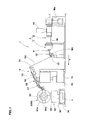
Fig. 1] Fig. 1 is an overall side view of a rubber member manufacturing device showing an embodiment of the present invention. - [
Fig. 2] Fig. 2 is a partially enlarged view of a rubber-extruding unit ofFig. 1 . - [
Figs. 3] Fig. 3(A) is a cross-sectional view ofFig. 2 taken along a line A-A;Fig. 3(B) is a cross-sectional view ofFig. 2 taken along a line B-B. - [
Fig. 4] Fig. 4 is a partially enlarged view explaining a rubber applicator. - [
Fig. 5] Fig. 5 is a cross-sectional view of a lower conveyor portion ofFig. 4 . - [
Fig. 6] Fig. 6 is a cross-sectional view of an upper conveyor portion ofFig. 4 . - [
Fig. 7] Fig. 7 is an enlarged view of a cutting portion. - [
Fig. 8] Fig. 8 is graphs showing relations between time and numbers of rotations of the first to third motors. - [
Fig. 9] Fig. 9 is an overall side view of a conventional rubber strip manufacturing device. -
- 1
- Rubber strip manufacturing device
- 2
- winding-around body
- 3
- Rubber extruder
- 4
- Calender head
- 5
- Rubber applicator
- 6
- Rubber extruder main body
- 6b
- Screw shaft
- 7
- Gear pump
- 12
- Pulling roll
- 70
- Control unit
- G1
- Rubber body
- G2
- Rubber strip
- M1
- First motor
- M2
- Second motor
- M3
- Third motor
- Hereinafter, an embodiment of the present invention will be described with referent to the drawings.
- As shown in
Fig. 1 , the manufacturing device 1 for a rubber strip in the present embodiment continuously manufactures a tape-like rubber strip G2 made of unvulcanized rubber. - The manufacturing device 1 in the present embodiment has a
rubber extruder 3, acalender head 4a, and pulling rolls 12. The pulling rolls 12 are provided for pulling the rubber strip G2 disposed on a downstream-side of thecalender head 4. -
Fig. 2 is a partially enlarged view of therubber extruder 3. Therubber extruder 3 has a rubber extrudermain body 6 and agear pump 7. - The rubber extruder
main body 6 has acylinder 6b, ascrew shaft 6c, and anextrusion head 6e. Thecylinder 6b is substantially cylindrical. Thecylinder 6b is provided on its one end side with an input opening 6a through which the unvulcanized rubber members and various compounding agents are thrown in. Thescrew shaft 6c is housed in thecylinder 6b. Thescrew shaft 6c is rotary-driven by a motor Ma with reduction gears (shown inFig. 1 ). Theextrusion head 6e is provided wi th an outlet openi ng 6d to extrude the unvulcanized rubber pushed ahead by thescrew shaft 6c. - The
gear pump 7 is connected to theoutlet opening 6d of the rubber extrudermain body 6 and composed as a constant-volume type extruding pump. Thegear pump 7 has acasing 7a, arubber chamber 7b formed inside thecasing 7a, and a pair of extrusion gears 7c engaging one another inside therubber chamber 7b. - The
rubber chamber 7b has an inlet port 7bi disposed on an upstream-side of the rubber extruding direction (x) (hereinafter so-called simply an "upstream-side"), and an outlet port 7bo disposed on a downstream-side of the rubber extruding direction (x) (hereinafter so-called simply a "downstream-side"). Moreover, therubber chamber 7b is positioned between the inlet port 7bi and the outl et port 7bo and has a gear storage space 7bm for housi ng theextrusion gear 7c. - The inlet port 7bi of the
rubber chamber 7b is communicated with theoutlet opening 6d of the rubber extrudermain body 6. Therefore, the unvulcanized rubber force-fed by the rubber extrudermain body 6 is supplied into therubber chamber 7b through the inlet port 7bi. - The
extrusion gear 7c is rotary-driven by a first motor M1. Thereby, the rubber member flowed from the inlet port 7bi to therubber chamber 7b is filled in a tooth groove of the rollingextrusion gear 7c, and force-fed quantitatively to the outlet port 7bo side. - The
gear pump 7 has a pressure sensor S1 which can detect a rubber pressure on the inlet port 7bi side of therubber chamber 7b, and a pressure sensor S2 which can detect a rubber pressure on outlet port 7bo side of therubber chamber 7b. In the present embodiment, the motor Ma with reduction gears (shown inFig. 1 ) of the rubber extrudermain body 6 is rotation-controlled so that the rubber pressure on the inlet port 7bi side of therubber chamber 7b keeps constant. The control is operated in acontrol unit 70. - The outl et port 7bo of the
rubber chamber 7b i s connected with aextrusion head 8. Theextrusion head 8 has a headmain body 8a, and anozzle die 8b with anopening 8c. The headmain body 8a is formed to have a block-like shape and fixed exchangeably on the downstream-side of thecasing 7a of thegear pump 7. And thenozzle die 8b is attached exchangeably to the headmain body 8a. The rubber member whi ch force-fed from the outl et port 7bo of therubber chamber 7b is extruded as a tape-like rubber body G1 preformed by the openi ng 8c of theextrusion head 8. -
Fig. 3(A) is a cross-secti onal view ofFig. 2 taken along line A-A. As shown inFig. 3(A) , theopening 8c of the nozzle die 8b in the present embodiment is formed in a horizontally long rectangular shape. Thereby, therubber extruder 3 can continuously extrude a rubber body (rubber strip) G1 having the substantially same cross-sectional shape (horizontally long rectangular shape) as theopening 8c of the nozzle die 8b. - when a thickness t1 and a width w1 of the rubber body G1 are small, molding accuracy may possibly decrease. Conversely, if the thickness t1 and the width w1 of the rubber body G1 are large, there is a tendency that the cross-sectional shape of the rubber member can not be shaped with a high degree of accuracy. Based on thi s perspective, the thickness t1 of the rubber body G1 is preferably not less than 0.4 mm, more preferably not less than 0.6 mm, and preferably not more than 3 mm, more preferably not more than 2 mm. Similarly, the width w1 of the rubber body G1 is preferably not less than 10 mm, more preferably not less than 20 mm, and preferably not more than 100 mm, more preferably not more than 90 mm. Needless to say, the diameters and the cross-sectional shape of the rubber body G1 is not limited to the above-mentioned ranges.
- As shown in
Fig. 2 , the rubber body G1 continuously extruded by therubber extruder 3 is transferred to acalender head 4. Thecalender head 4 is disposed on a downstream-side of theextrusion head 8. Thecalender head 4 has a pair ofcalender rollers gap adjusting device 10. - The
calender rollers calender rollers main body 4c, respectively. The rotational axes of thecalender rollers calender rollers control unit 70. - The
gap adjusting device 10 displaces the pair of thecalender rollers gap adjusting device 10 has anactuator 11 such as a cylinder for a rectilinear operating, for example, and fixed in the upper part of the framemain body 4c. A rod of theactuator 11 is connected with theupper calender roller 4a. Therefore, when extending and retracting the rod of theactuator 11, theupper calender roller 4a can be moved up and down with respect to the framemain body 4c. Thereby, the upper andlower calender rollers -
Fig. 3(B) is a cross-sectional view of thecalender head 4 ofFig. 2 taken along the line B-B under the rolling state. The gap D between thecalender rollers Fig. 3(A) ). Thereby, the rubber body G1 is rolled and shaped into a rubber strip G2 having a width w2 (> w1) and a thickness t2 (< t1). - In order to increase the accuracy of the cross-sectional shape of the rubber member, it is desirable to minimize the thickness t2 of the rubber strip G2 as far as stable rolling is possible. Based on this perspective, the thickness t2 of the rubber strip G2 is preferably not less than 0.3 mm, more preferably not less than 0.4 mm and preferably not more than 3 mm, more preferably not more than 2 mm. The width w2 of the rubber strip G2 is preferably not less than 5 mm, more preferably not less than 7 mm, and preferably not more than 100 mm, more preferably not more than 90 mm, much more preferably 50 mm. The rubber strip G2 in the present embodiment is molded to have the thickness t2 of 0.5 mm and the width w2 of 25 mm.
- As shown in
Fig. 1 , the pullingrolls 12 exfoliate the rubber strip G2 extruded and molded by thecalender head 4 from thecalender rollers Fig. 2 ) and pulls. As to the pulling rolls 12, it may be possible to provide one set of the pulling rolls. In the present embodiment, two sets having the same configuration are di sposed in the rubber extracti ng di recti on (x) wi th a space left therebetween in order to preserve a stable exfoliating effectiveness. Both of the pullingrolls 12 rotate in the same direction so as to pull the rubber strip G2 in the downstream of the rubber extruding direction (x). These pulling rolls 12 are rotary-driven by a third motor M3. The third motor M3 is controlled in the control unit 70 (shown inFig. 2 ). - On the downstream-side of the manufacturing device 1 for a rubber strip in the present embodiment, there are disposed a
dancer roller 13, arubber applicator 5, and a winding-aroundbody 2, serially. Thereby, the manufacturing device 1 for a rubber strip in the present embodiment is able to compose a part of manufacturing device of the rubber member of the tire. - The
dancer roller 13 is a rotatably free roller. The rubber strip G2 is wrapped on thedancer roller 13 in a U-shape. Thedancer roller 13 moves freely up and down depending on its own weight and a tensile force of the rubber strip G2. Thereby, the rubber strip G2 extending between thedancer roller 13 and therubber applicator 5 has a constant tension. Therefore, a deflection of the rubber strip G2 is prevented. - The
rubber applicator 5 has a supportingrail 15 extending along the rubber extracting direction (x), amain body 16 disposed movably along the supportingrail 15, a up-and-down portion 17 being movable up and down along themain body 16, and aside frame 21 fixed in the up-and-down portion 17 via asupport 18. Therubber applicator 5 is arranged closely to thedancer roller 13. Therefore, in the present embodiment, there is shown an aspect where no festoon (not shown) is provided between therubber applicator 5 and thedancer roller 13. - As shown enlargedly in
Fig. 4 , theside frame 21 has a guidingroller 20 disposed on an upstream-side, aconveyor portion 22 disposed on a downstream-side of it, apasting portion 23 disposed on the downstream-side of theconveyor portion 22, and a cuttingportion 24 disposed in the substantial center of theconveyor portion 22. - The guiding
roller 20 is a rotatable roller having a horizontal axis and pivotally supported by theside frame 21. The rubber strip G2 is wrapped on the guidingroller 20. Between the guidingroller 20 and the dancer roller 13 (shown inFig. 1 ), there is no other roller to receive the rubber strip G2. - The
guide roller 20, for example, the outer diameter of the central portion in the axial direction is the largest, and the outer diameter is gradually reduced toward the outside in the axial direction, a so-called crown roller is preferably employed. Such crown roller can automatically correct a shifting or meandering of the rubber strip G2 and can guide the rubber strip G2 always at the largest diameter position of the roller. Therefore, the guidingroller 20 in the present embodiment can center the rubber strip G2 with a simple construction, and can supply it to theconveyor portion 22 on the downstream-side of the guidingroller 20. - The
conveyor portion 22 in the present embodiment has alower conveyor portion 26 and anupper conveyor portion 28, for example. - As shown separately in
Fig. 5 , thelower conveyor portion 26 has a plurality oflower guiding rollers sigh 30 is used), and a conveyingbelt 31 guided by thelower guiding rollers 30 so as to be movable therearound. - The lower gui di ng
roller 30 has at least a most-upstream roller 30a disposed in the uppermost-stream side of the conveying direction, a most-downstream roller 30b disposed in the downmost-stream side of the conveying direction, and a plurality ofrollers 30c-30k disposed therebetween. - The conveying
belt 31 runs in the outward-side region 31F for conveying the rubber strip G2 (shown inFig. 4 ) from the position of a most-upstream roller 30a to the position of the most-downstream roller 30b and supplying it to the winding-around body 2 (shown inFig. 4 ). The outward-side region 31F is set to be substantially flat at except an apical end of the downstream-side. After running in the outward-side region 31F, the conveyingbelt 31 turns back at the most-downstream roller 30b and runs in a homeward-side region 31R to return to the most-upstream roller 30a again. - The
side frame 21 in the present embodiment is provided in the outward-side region 31F withbackup plates belt 31. These backup plates 33-35 suppress a downward flexure of the conveyingbelt 31, and it helps to keep the conveyingbelt 31 straight in the outward-side region 31F. Between thebackup plate 33 and thebackup plate 34, there is a space. The space is provided with the above-mentionedcutting portion 24 to cut the rubber strip G2. The cuttingportion 24 will be discussed below. - As shown in
Fig. 4 , theupper conveyor portion 28 has an upstream-sideupper conveyor portion 28A and a downstream-sideupper conveyor portion 28B disposed on its downstream side. Between the upstream-sideupper conveyor portion 28A and the downstream-sideupper conveyor portion 28B, there is a space. As shown separately inFig. 6 , each of theupper conveyor portions pressing belt 39 guided in enabling go-around by a plurality ofupper guiding rollers sigh 38 is used). - The upper gui di ng
roller 38 of each of theupper conveyor portions side roller 38a in the conveying direction, a most-downstream-side roller 38b in the conveying direction, and aroller 38c disposed therebetween. Eachpressing bel t 39 is wrapped around the most-upstream-si deroller 38a and the most-downstream-side roller 38b, and execute a continuous go-around movement. Moreover, each of theupper conveyor portions pressing roller 38d to push down an inner periphery of thepressing belt 39, respectively. Thepressing belt 39 is disposed so as to face to face with a conveying belt 31 (shown inFig. 5 ). - As shown in
Fig. 4 , theconveyor portion 22 in the present embodiment has a connectingmeans 40. The connecting means 40 is a well-known means for transmitting a rotational force utilizing, for example, a chain, a belt, a sprocket, a gear or the like. For example, the connectingmeans 40 synchronizes any one of the lower gui di ngrollers 30 wi th any one of the upper gui di ngrollers 38. The synchronized lower guidingroller 30 and upper guidingroller 38 have the same outer diameters. Thereby, the conveyingbelt 31 of thelower conveyor portion 26 and thepressing belt 39 of theupper conveyor portion 28 are synchronized one another, and to be driven at the same speed. - The
conveyor portion 22 composed the above, a tip of the rubber strip G2 is inserted between thelower conveyor portion 26 and the upstream-sideupper conveyor portion 28A. In theconveyor portion 22, the rubber strip G2 is sandwiched between the conveyingbelt 31 of thelower conveyor portion 26 and thepressing belt 39 of theupper conveyor portion 28, and the rubber strip G2 can be conveyed by utilizing their frictional force. Theconveyor portion 22 in such sandwich-type conveying system does not require self-bonding properties of the rubber strip G2 especially, therefore, stable conveying is possible without being affected by physical properties of the rubber strip G2. - A conveying speed V2 of the rubber strip by the
conveyor portion 22 is desirably set in a range of from 70% to 100% of a supplying speed V1 of the rubber strip G2 from thecalender head 4. The rubber strip G2 is conveyed wi thout deflection between thedancer roller 13 and theconveyor portion 22. - As shown in
Fig. 4 , thepasting portion 23 works as a pressing means to press the rubber strip G2 transferred from theconveyor portion 22 on the rotating winding-aroundbody 2, for example. The pasti ngportion 23 has acylinder 44 and apressing roller 46. Thecylinder 44 is disposed on the downstream-side than theconveyor portion 22 via theframe 42 disposed in theside frame 21. Thecylinder 44 has an extendable rod. Thepressing roller 46 is attached rotatably to a rod apex of thecylinder 44. Thepressing roller 46 can move closer to or away from the winding-aroundbody 2 by the expansion or contraction of the rod of thecylinder 44. - As shown in
Fig. 7 enlargedly, the cuttingportion 24 has abracket 50 extruding upward from theside frame 21; arotational axis 52 being enabling rotary drive by a stepping motor (not shown) disposed in thebracket 50, for example; and acutting blade 51 fixed to arotational axis 52. - As shown in
Fig. 6 , the cuttingportion 24 is disposed between the upstream-sideupper conveyor portion 28A and the downstream-sideupper conveyor portion 28B. Thecutting blade 51 may be a flat blade extending in the width direction of the rubber strip G2, for example, as shown inFig. 7 . Also, it may be a spiral blade (not shown) extending spirally around therotational axis 52. It is desirable that the lower guiding roller 30 (30h) supports the underside of the conveyingbelt 31 pushed down by thecutting blade 51 so as to absorb a flexure and a shock. - As shown in
Fig. 1 , the winding-aroundbody 2 in the present embodiment is configured as a cylindrical former 60. The former 60 is configured as a rigid inner mold whose outer surface has the shape of the inner circumferential surface of the finished tire to be formed. The inner mol d is of a built-up type and is formed annularly by arranged the fan-shapedsegments 60a. The former 60 is supported by theformer supporter device 62 and rotary-driven. - The
former supporter device 62 has arail 64, aslide portion 66, amain portion 68, and a supportingportion 69. Therail 64 extends horizontally in the perpendicular di recti on to the rubber extracti ng di recti on (x). Themain portion 68 is supported rotatably around a vertical z-axis with respect to theslide portion 66. The supportingportion 69 has a chuck portion extending upward from themain portion 68 and supporting the former 60 in a cantilever. - A function of the manufacturing device 1 for a rubber strip (including a manufacturing method of the rubber strip G2) formed in the above-mentioned
composition wi 11 be described. A motor Ma of the rubber extrudermain body 6 is driven, and the unvulcanized rubber is kneaded in thecylinder 6b. - As shown in
Fig. 2 , thecontrol unit 70 drives thegear pump 7 of therubber extruder 3 by starting the first motor M1 after reaching the rubber pressure on the inlet port side of therubber chamber 7b to a predetermined value. In the uppermost part inFig. 8 , a graphs relations between time and a number of rotation of the first motor M1 is illustrated. The number of rotation of the first motor is controlled so as to become approximately-constant after linearly increasing from zero. Thereby, the rubber body G1 is extruded stably from therubber extruder 3. - As shown in
Fig. 2 , thecontrol unit 70 drives the second motor M2 with the drive of the first motor M1. The second motor M2 is controlled in conjunction with the first motor M1 for rotary-driving thegear pump 7. That is to say, as illustrated in a middle area ofFig. 8 , the number of rotation of the second motor M2 is controlled so as to become approximately-constant at the substantially same time T1 after linearly increasing from zero. By this drive of the second motor M2, thecalender rollers calender head 4 are rotated. Thereby, the rubber body G1 is rolled and the rubber strip G2 is formed. - In a general way, in the
gear pump 7, the number of rotation of theextrusion gear 7c is proportional to a discharging speed of the rubber body G1 extruded from it. In the present i nventi on, the number of rotation of thecalender rollers extrusion gear 7c of thegear pump 7, that is, a speed of supply of the rubber body G1. - According to the present invention, for example, when the discharging speed of the rubber body G1 from the
gear pump 7 increases with the increase of the number of rotation of the first motor M1, the number of rotation of thecalender rollers calender roller 4a, and it is possible to avoid formation of the rubber strip G2, for example, having a larger width than a targeted value. - Conversely, when the number of rotation of the first motor M1 is decreased and the extrusion speed of the rubber body G1 from the
gear pump 7 is decreased, the number of rotation of thecalender rollers calender roller 4a, and it is possible to avoid formation of the rubber strip G2 having a larger width than a targeted value. - As shown in
Fig. 2 , thecontrol uni t 70 drives the thi rd motor M3 with the drive of the first motor M1. Thereby, the pullingrolls 12 rotate and the rubber strip G2 is pulled from thecalender rollers gear pump 7. That is to say, as illustrated in a lowermost part ofFig. 8 , the number of rotation of the third motor M3 is also controlled so as to become approximately-constant at the substantially same time T1 after linearly increasing from zero. - According to the present invention, for example, when the discharging speed of the rubber body G1 from the
gear pump 7 increases with the increase of the number of rotation of the first motor M1, not only the number of rotation of thecalender rollers rolls 12 also increase accordingly. Therefore, the rubber strip G2 formed wi th hi gh accuracy by thecalender roller 4a can be pulled stably. In the present embodiment, a circumferential velocity of the pulling rolls 12 is set to be the same as or slightly larger than a circumferential velocity of thecalender rollers calender rollers - As shown in
Fig. 1 , the manufactured rubber strip G2 is supplied via thedancer roller 13 directly to arubber applicator 5 without an intermediary such as festoon. In therubber applicator 5, the rubber strip G2 is conveyed to the winding-aroundbody 2 by theconveyor portion 22. One end of the rubber strip G2 is fixed onto the winding-aroundbody 2 and wound spirally by rotating the winding-aroundbody 2. Because the rubber strip G2 is dimensionally stable, by moving the former 60, the rubber member having various cross-sectional shapes can be formed with a high accuracy. - After winding the rubber strip G2 around the former 60, as shown in
Fig. 7 , the cuttingportion 24 rotates therotational axis 52 one revolution in the direction that synchronizes with the conveying direction of the rubber strip G2. Thereby, thecutting blade 51 can press the rubber strip G2 and the conveyingbelt 31. The rubber strip G2 and the conveyingbelt 31 which are pressed by thecutting blade 51, are sandwiched between the cuttingblade 51 and thelower guiding roller 30. Thereby, the rubber strip G2 is cut. Meanwhile it is desirable that he circumferential velocity of thecutting blade 51 is the same as the speed of the rubber strip G2 conveying theconveyor portion 22. The timing of the cut of the rubber strip G2 is previously controlled by the control unit. - After the cut of the rubber strip G2 by the cutting
portion 24, the conveyance of theconveyor portion 22, the operation of thegear pump 7 and the rotations of thecalender rollers rubber extruder 3 and therubber applicator 5 is match. - However, it is desirable that the rubber extruder main body 6 (screw
shaft 6c) keep its continuous operation without halting. This means that, the rubber is appropriately circulated in thecylinder 6b so as to maintain the high rubber pressure in thecylinder 6b during halting of thegear pump 7. Thereby, at the time of resuming the operation of thegear pump 7, the rubber can be immediately extruded in a fixed quantity. - With the rotations stopped, the
calender rollers calender rollers calender head 4 and therubber extruder 3. - Like the present embodiment, under halted state of the
calender rollers lower calender rollers lower calender rollers - In the present embodiment, the former 60 after forming the rubber member is changed wi th another former 60. After the change of
formers 60, the gap of thecalender rollers conveyor portion 22 and the operations of thegear pump 7, thecalender rollers roll 12 are immediately restarted, respectively. The inside of therubber chamber 7b of thegear pump 7 is filled with the rubber owing to the continuous operation of the rubber extrudermain body 6. Therefore, at the same time as the restarting of operation, thegear pump 7 can supply the rubber body G1 stably. - Hereinbefore, the embodiment of the present invention was described, but it will be obvious that various changes may be made without limitation to what was described in the above.
Claims (6)
- A rubber strip manufacturing device
which is a device to manufacture a tape-like rubber strip made of unvulcanized rubber, and
which is characterized by including
a rubber extruder comprising
a rubber extruder main body having a screw shaft for kneading and pushing the unvulcanized rubber toward an outlet opening, and
a gear pump connected to the outlet opening of the rubber extruder main body and rotary-driven by a first motor;
a calender head comprising a pair of calender rollers for rolling a shaped rubber body extruded from the rubber extruder to obtain the rubber strip; and
a control unit for controlling a second motor for rotary-driving the calender rollers in conjunction with the first motor. - The rubber strip manufacturing device as set forth in claim 1, wherein said control unit controls the number of rotation of the second motor based on the number of rotation of the first motor.
- The rubber strip manufacturing device as set forth in claim 1 or 2, wherein, on a downstream-side of the calender head, a pulling roll for pulling the rubber strip rolled by the calender rollers is provided, and
the control unit controls a third motor for rotary-driving the pulling roll in conjunction with the first motor. - A rubber strip manufacturing method
which is a method for manufacturing a tape-like rubber strip made of unvulcanized rubber, and
which is characterized by including
an extruding step to extrude a long tape-like shaped rubber body of the unvulcanized rubber by use of a rubber extruder comprising a rubber extruder main body having a screw shaft for kneading and
pushing the unvulcanized rubber toward an outlet opening, and a gear pump connected to the outlet openi ng of the rubber extruder main body and rotary-driven by a first motor, and
a rolling step to roll the shaped rubber body wi th the cal ender rollers so as to form the rubber strip,
wherein, in the rolling step, a second motor for rotary-driving the calender rollers is controlled in conjunction with the first motor. - The rubber strip manufacturing method as set forth in claim 4, wherein in the rolling step, the number of rotation of the second motor is controlled based on the number of rotation of the first motor.
- The rubber strip manufacturing method as set forth in claim 4 or 5, which comprises a pulling step to pull the rubber strip rolled by the calender rollers by use of a pulling roll disposed on a downstream-side of the calender head, and
in the pulling step, a third motor for rotary-driving the pulling roll is controlled in conjunction with the first motor.
Applications Claiming Priority (2)
| Application Number | Priority Date | Filing Date | Title |
|---|---|---|---|
| JP2012203240A JP5715606B2 (en) | 2012-09-14 | 2012-09-14 | Rubber strip manufacturing apparatus and manufacturing method |
| PCT/JP2013/073402 WO2014042021A1 (en) | 2012-09-14 | 2013-08-30 | Rubber strip manufacturing device and manufacturing method |
Publications (3)
| Publication Number | Publication Date |
|---|---|
| EP2886295A1 true EP2886295A1 (en) | 2015-06-24 |
| EP2886295A4 EP2886295A4 (en) | 2016-05-25 |
| EP2886295B1 EP2886295B1 (en) | 2018-03-21 |
Family
ID=50278138
Family Applications (1)
| Application Number | Title | Priority Date | Filing Date |
|---|---|---|---|
| EP13837883.1A Active EP2886295B1 (en) | 2012-09-14 | 2013-08-30 | Rubber strip manufacturing device and manufacturing method |
Country Status (5)
| Country | Link |
|---|---|
| US (1) | US9902097B2 (en) |
| EP (1) | EP2886295B1 (en) |
| JP (1) | JP5715606B2 (en) |
| CN (1) | CN104582934B (en) |
| WO (1) | WO2014042021A1 (en) |
Families Citing this family (16)
| Publication number | Priority date | Publication date | Assignee | Title |
|---|---|---|---|---|
| US11685095B2 (en) | 2015-06-30 | 2023-06-27 | The Goodyear Tire & Rubber Company | Method and apparatus for forming tire components using a coextruded strip |
| JP6607520B2 (en) * | 2015-12-11 | 2019-11-20 | 住友ゴム工業株式会社 | Gear pump extruder |
| CN110177681B (en) * | 2016-12-16 | 2022-01-18 | 倍耐力轮胎股份公司 | Method for inspecting a continuous elongated element during the building of a tyre for vehicle wheels and apparatus for building a tyre for vehicle wheels |
| CN106738425B (en) * | 2017-01-22 | 2023-11-17 | 中国铁道科学研究院铁道建筑研究所 | Rubber product production device comprising information monitoring mechanism |
| CN107336393B (en) * | 2017-06-28 | 2019-10-25 | 安徽工程大学 | A smart watch strap rapid prototyping device |
| JP6939382B2 (en) * | 2017-10-12 | 2021-09-22 | 住友ゴム工業株式会社 | Multi-layer rubber member manufacturing equipment and manufacturing method |
| CN108327151A (en) * | 2018-03-26 | 2018-07-27 | 联亚智能科技(苏州)有限公司 | A kind of adhesive tape multistage molding press device and rubber components wind unit |
| US10532512B2 (en) * | 2018-06-07 | 2020-01-14 | Thermwood Corporation | Additive manufacturing apparatus |
| FR3089846A3 (en) * | 2018-12-14 | 2020-06-19 | Michelin & Cie | Joining system for rubber bands to feed an extruder |
| JP6784862B1 (en) * | 2020-03-31 | 2020-11-11 | 日東電工株式会社 | Plastic fiber optic manufacturing equipment and gear pump |
| EP4225547A4 (en) * | 2020-10-09 | 2024-08-21 | University of Delaware | Positive displacement pump material delivery system for additive manufacture |
| CN113183440B (en) * | 2021-04-28 | 2023-01-24 | 重庆科技学院 | Butyl rubber vibration damping belt production line and tension control method |
| CN113858568B (en) * | 2021-10-12 | 2022-04-12 | 天津赛象科技股份有限公司 | Adhesive tape width closed-loop control method and control device |
| JP7832441B2 (en) * | 2021-10-19 | 2026-03-18 | 横浜ゴム株式会社 | Method and apparatus for manufacturing annular rubber member |
| CN114536701A (en) * | 2021-11-26 | 2022-05-27 | 浙江天铁实业股份有限公司 | Rubber sheet preforming process for vulcanization of shock insulation support |
| JP7729204B2 (en) * | 2021-12-28 | 2025-08-26 | 住友ゴム工業株式会社 | Gear pump for rubber composition and rubber member forming device |
Family Cites Families (14)
| Publication number | Priority date | Publication date | Assignee | Title |
|---|---|---|---|---|
| JPS60901B2 (en) * | 1980-07-03 | 1985-01-10 | 日立電線株式会社 | extruder |
| JPH0637065B2 (en) | 1989-11-21 | 1994-05-18 | 東芝機械株式会社 | Bank amount monitoring method, sheet forming method, sheet temperature measuring method therefor, and apparatus therefor |
| DE4004512A1 (en) * | 1990-02-14 | 1991-08-22 | Hoechst Ag | METHOD FOR PRODUCING PHOTOPOLYMER PLATES |
| JP4420491B2 (en) | 1998-06-29 | 2010-02-24 | 株式会社ブリヂストン | Method and apparatus for attaching rubber material for tire component |
| EP1486320B1 (en) * | 2002-02-22 | 2008-12-31 | Bridgestone Corporation | Thin rubber member producing method, rubber rolling device, and rubber rolling method |
| JP2003266555A (en) * | 2002-03-18 | 2003-09-24 | Toyo Tire & Rubber Co Ltd | Strip rubber continuous molding equipment and continuous molding method |
| JP2006043908A (en) | 2004-07-30 | 2006-02-16 | Sumitomo Rubber Ind Ltd | Tire manufacturing method |
| JP4426937B2 (en) | 2004-09-14 | 2010-03-03 | 住友ゴム工業株式会社 | Rubber strip manufacturing equipment |
| JP4769516B2 (en) * | 2005-08-23 | 2011-09-07 | 東芝機械株式会社 | Sheet forming apparatus and control method thereof |
| US20070126144A1 (en) * | 2005-12-02 | 2007-06-07 | Yadong Jin | Polish/texture thermoplastic film and method for making the same |
| CN101505949B (en) * | 2006-08-09 | 2013-11-06 | 倍耐力轮胎股份公司 | Method and apparatus for building pneumatic tires |
| JP5152889B2 (en) * | 2006-11-20 | 2013-02-27 | 株式会社ブリヂストン | Ribbon rubber molding machine |
| JP2009137034A (en) * | 2007-12-03 | 2009-06-25 | Toyo Tire & Rubber Co Ltd | Strip rubber extrusion apparatus and strip rubber extrusion method |
| JP5351931B2 (en) * | 2011-06-07 | 2013-11-27 | 住友ゴム工業株式会社 | Rubber strip manufacturing apparatus and manufacturing method using the same |
-
2012
- 2012-09-14 JP JP2012203240A patent/JP5715606B2/en active Active
-
2013
- 2013-08-30 EP EP13837883.1A patent/EP2886295B1/en active Active
- 2013-08-30 CN CN201380045562.1A patent/CN104582934B/en active Active
- 2013-08-30 WO PCT/JP2013/073402 patent/WO2014042021A1/en not_active Ceased
- 2013-08-30 US US14/422,769 patent/US9902097B2/en active Active
Also Published As
| Publication number | Publication date |
|---|---|
| JP2014058064A (en) | 2014-04-03 |
| WO2014042021A1 (en) | 2014-03-20 |
| CN104582934B (en) | 2017-03-29 |
| JP5715606B2 (en) | 2015-05-07 |
| US9902097B2 (en) | 2018-02-27 |
| US20150231804A1 (en) | 2015-08-20 |
| EP2886295A4 (en) | 2016-05-25 |
| EP2886295B1 (en) | 2018-03-21 |
| CN104582934A (en) | 2015-04-29 |
Similar Documents
| Publication | Publication Date | Title |
|---|---|---|
| EP2886295B1 (en) | Rubber strip manufacturing device and manufacturing method | |
| JP6030910B2 (en) | Rubber member manufacturing equipment | |
| JP3322648B2 (en) | Rubber conveying device and rubber molding device using the same | |
| EP2532505B1 (en) | Method for manufacturing raw rubber strip | |
| CN1966252B (en) | Device to apply rubber tape | |
| CN100386194C (en) | Apparatus for manufacturing tire reinforcement structures comprising a strip turning mechanism | |
| CN104936759A (en) | Apparatus and method for extruding elastomer mixture | |
| US20170297285A1 (en) | Bead core covering method and bead core covering device | |
| JP6644626B2 (en) | Bead core coating method and bead core coating device | |
| JP6743476B2 (en) | Rubber strip attachment device | |
| JP6082220B2 (en) | Rubber strip sticking device | |
| EP2347893B1 (en) | Tire manufacturing device and tire manufacturing method | |
| EP2301738B1 (en) | Forming device and forming method for rubber member | |
| CN103097118B (en) | Method and apparatus for manufacturing tire blanks from strips | |
| JP2013220569A (en) | Method of molding cylindrical rubber member | |
| JP7832441B2 (en) | Method and apparatus for manufacturing annular rubber member | |
| JP4451979B2 (en) | Extrusion / molding method and apparatus | |
| JP2005186586A (en) | Manufacturing method of raw rubber wound body for tire and tire using the same | |
| NL2037260B1 (en) | Method, extruder device and tire building machine for winding a strip around a strip-winding drum to form a tire component | |
| JP2008126497A (en) | Ribbon-shaped rubber molding apparatus and molding method | |
| JP4904049B2 (en) | Pneumatic tire manufacturing method | |
| JP2009126143A (en) | Strip rubber continuous molding equipment and strip rubber continuous molding method | |
| WO2001010627A1 (en) | A method for the production of a rubber semifinished product and extruder for implementing this method | |
| JP2009143165A (en) | Tire manufacturing method and manufacturing apparatus | |
| JP2008018571A (en) | Die head, rubber extruder and strip rubber winding device |
Legal Events
| Date | Code | Title | Description |
|---|---|---|---|
| PUAI | Public reference made under article 153(3) epc to a published international application that has entered the european phase |
Free format text: ORIGINAL CODE: 0009012 |
|
| 17P | Request for examination filed |
Effective date: 20150320 |
|
| AK | Designated contracting states |
Kind code of ref document: A1 Designated state(s): AL AT BE BG CH CY CZ DE DK EE ES FI FR GB GR HR HU IE IS IT LI LT LU LV MC MK MT NL NO PL PT RO RS SE SI SK SM TR |
|
| AX | Request for extension of the european patent |
Extension state: BA ME |
|
| DAX | Request for extension of the european patent (deleted) | ||
| RA4 | Supplementary search report drawn up and despatched (corrected) |
Effective date: 20160428 |
|
| RIC1 | Information provided on ipc code assigned before grant |
Ipc: B29K 21/00 20060101ALI20160421BHEP Ipc: B29C 47/36 20060101ALI20160421BHEP Ipc: B29C 47/92 20060101AFI20160421BHEP Ipc: B29C 47/34 20060101ALI20160421BHEP Ipc: B29D 30/60 20060101ALI20160421BHEP Ipc: B29C 47/38 20060101ALI20160421BHEP Ipc: B29C 47/00 20060101ALI20160421BHEP Ipc: B29C 47/32 20060101ALI20160421BHEP Ipc: B29D 30/30 20060101ALI20160421BHEP Ipc: B29C 47/90 20060101ALI20160421BHEP |
|
| STAA | Information on the status of an ep patent application or granted ep patent |
Free format text: STATUS: EXAMINATION IS IN PROGRESS |
|
| 17Q | First examination report despatched |
Effective date: 20170308 |
|
| GRAP | Despatch of communication of intention to grant a patent |
Free format text: ORIGINAL CODE: EPIDOSNIGR1 |
|
| STAA | Information on the status of an ep patent application or granted ep patent |
Free format text: STATUS: GRANT OF PATENT IS INTENDED |
|
| INTG | Intention to grant announced |
Effective date: 20171219 |
|
| GRAS | Grant fee paid |
Free format text: ORIGINAL CODE: EPIDOSNIGR3 |
|
| GRAA | (expected) grant |
Free format text: ORIGINAL CODE: 0009210 |
|
| STAA | Information on the status of an ep patent application or granted ep patent |
Free format text: STATUS: THE PATENT HAS BEEN GRANTED |
|
| AK | Designated contracting states |
Kind code of ref document: B1 Designated state(s): AL AT BE BG CH CY CZ DE DK EE ES FI FR GB GR HR HU IE IS IT LI LT LU LV MC MK MT NL NO PL PT RO RS SE SI SK SM TR |
|
| REG | Reference to a national code |
Ref country code: GB Ref legal event code: FG4D |
|
| REG | Reference to a national code |
Ref country code: CH Ref legal event code: EP |
|
| REG | Reference to a national code |
Ref country code: AT Ref legal event code: REF Ref document number: 980621 Country of ref document: AT Kind code of ref document: T Effective date: 20180415 |
|
| REG | Reference to a national code |
Ref country code: IE Ref legal event code: FG4D |
|
| REG | Reference to a national code |
Ref country code: DE Ref legal event code: R096 Ref document number: 602013034841 Country of ref document: DE |
|
| REG | Reference to a national code |
Ref country code: NL Ref legal event code: MP Effective date: 20180321 |
|
| PG25 | Lapsed in a contracting state [announced via postgrant information from national office to epo] |
Ref country code: NO Free format text: LAPSE BECAUSE OF FAILURE TO SUBMIT A TRANSLATION OF THE DESCRIPTION OR TO PAY THE FEE WITHIN THE PRESCRIBED TIME-LIMIT Effective date: 20180621 Ref country code: HR Free format text: LAPSE BECAUSE OF FAILURE TO SUBMIT A TRANSLATION OF THE DESCRIPTION OR TO PAY THE FEE WITHIN THE PRESCRIBED TIME-LIMIT Effective date: 20180321 Ref country code: CY Free format text: LAPSE BECAUSE OF FAILURE TO SUBMIT A TRANSLATION OF THE DESCRIPTION OR TO PAY THE FEE WITHIN THE PRESCRIBED TIME-LIMIT Effective date: 20180321 Ref country code: LT Free format text: LAPSE BECAUSE OF FAILURE TO SUBMIT A TRANSLATION OF THE DESCRIPTION OR TO PAY THE FEE WITHIN THE PRESCRIBED TIME-LIMIT Effective date: 20180321 Ref country code: FI Free format text: LAPSE BECAUSE OF FAILURE TO SUBMIT A TRANSLATION OF THE DESCRIPTION OR TO PAY THE FEE WITHIN THE PRESCRIBED TIME-LIMIT Effective date: 20180321 |
|
| REG | Reference to a national code |
Ref country code: LT Ref legal event code: MG4D |
|
| REG | Reference to a national code |
Ref country code: AT Ref legal event code: MK05 Ref document number: 980621 Country of ref document: AT Kind code of ref document: T Effective date: 20180321 |
|
| REG | Reference to a national code |
Ref country code: FR Ref legal event code: PLFP Year of fee payment: 6 |
|
| PG25 | Lapsed in a contracting state [announced via postgrant information from national office to epo] |
Ref country code: GR Free format text: LAPSE BECAUSE OF FAILURE TO SUBMIT A TRANSLATION OF THE DESCRIPTION OR TO PAY THE FEE WITHIN THE PRESCRIBED TIME-LIMIT Effective date: 20180622 Ref country code: SE Free format text: LAPSE BECAUSE OF FAILURE TO SUBMIT A TRANSLATION OF THE DESCRIPTION OR TO PAY THE FEE WITHIN THE PRESCRIBED TIME-LIMIT Effective date: 20180321 Ref country code: LV Free format text: LAPSE BECAUSE OF FAILURE TO SUBMIT A TRANSLATION OF THE DESCRIPTION OR TO PAY THE FEE WITHIN THE PRESCRIBED TIME-LIMIT Effective date: 20180321 Ref country code: RS Free format text: LAPSE BECAUSE OF FAILURE TO SUBMIT A TRANSLATION OF THE DESCRIPTION OR TO PAY THE FEE WITHIN THE PRESCRIBED TIME-LIMIT Effective date: 20180321 Ref country code: BG Free format text: LAPSE BECAUSE OF FAILURE TO SUBMIT A TRANSLATION OF THE DESCRIPTION OR TO PAY THE FEE WITHIN THE PRESCRIBED TIME-LIMIT Effective date: 20180621 |
|
| PG25 | Lapsed in a contracting state [announced via postgrant information from national office to epo] |
Ref country code: PL Free format text: LAPSE BECAUSE OF FAILURE TO SUBMIT A TRANSLATION OF THE DESCRIPTION OR TO PAY THE FEE WITHIN THE PRESCRIBED TIME-LIMIT Effective date: 20180321 Ref country code: EE Free format text: LAPSE BECAUSE OF FAILURE TO SUBMIT A TRANSLATION OF THE DESCRIPTION OR TO PAY THE FEE WITHIN THE PRESCRIBED TIME-LIMIT Effective date: 20180321 Ref country code: IT Free format text: LAPSE BECAUSE OF FAILURE TO SUBMIT A TRANSLATION OF THE DESCRIPTION OR TO PAY THE FEE WITHIN THE PRESCRIBED TIME-LIMIT Effective date: 20180321 Ref country code: AL Free format text: LAPSE BECAUSE OF FAILURE TO SUBMIT A TRANSLATION OF THE DESCRIPTION OR TO PAY THE FEE WITHIN THE PRESCRIBED TIME-LIMIT Effective date: 20180321 Ref country code: ES Free format text: LAPSE BECAUSE OF FAILURE TO SUBMIT A TRANSLATION OF THE DESCRIPTION OR TO PAY THE FEE WITHIN THE PRESCRIBED TIME-LIMIT Effective date: 20180321 Ref country code: NL Free format text: LAPSE BECAUSE OF FAILURE TO SUBMIT A TRANSLATION OF THE DESCRIPTION OR TO PAY THE FEE WITHIN THE PRESCRIBED TIME-LIMIT Effective date: 20180321 Ref country code: RO Free format text: LAPSE BECAUSE OF FAILURE TO SUBMIT A TRANSLATION OF THE DESCRIPTION OR TO PAY THE FEE WITHIN THE PRESCRIBED TIME-LIMIT Effective date: 20180321 |
|
| REG | Reference to a national code |
Ref country code: DE Ref legal event code: R079 Ref document number: 602013034841 Country of ref document: DE Free format text: PREVIOUS MAIN CLASS: B29C0047920000 Ipc: B29C0048920000 |
|
| PG25 | Lapsed in a contracting state [announced via postgrant information from national office to epo] |
Ref country code: AT Free format text: LAPSE BECAUSE OF FAILURE TO SUBMIT A TRANSLATION OF THE DESCRIPTION OR TO PAY THE FEE WITHIN THE PRESCRIBED TIME-LIMIT Effective date: 20180321 Ref country code: CZ Free format text: LAPSE BECAUSE OF FAILURE TO SUBMIT A TRANSLATION OF THE DESCRIPTION OR TO PAY THE FEE WITHIN THE PRESCRIBED TIME-LIMIT Effective date: 20180321 Ref country code: SK Free format text: LAPSE BECAUSE OF FAILURE TO SUBMIT A TRANSLATION OF THE DESCRIPTION OR TO PAY THE FEE WITHIN THE PRESCRIBED TIME-LIMIT Effective date: 20180321 Ref country code: SM Free format text: LAPSE BECAUSE OF FAILURE TO SUBMIT A TRANSLATION OF THE DESCRIPTION OR TO PAY THE FEE WITHIN THE PRESCRIBED TIME-LIMIT Effective date: 20180321 |
|
| PG25 | Lapsed in a contracting state [announced via postgrant information from national office to epo] |
Ref country code: PT Free format text: LAPSE BECAUSE OF FAILURE TO SUBMIT A TRANSLATION OF THE DESCRIPTION OR TO PAY THE FEE WITHIN THE PRESCRIBED TIME-LIMIT Effective date: 20180723 |
|
| REG | Reference to a national code |
Ref country code: DE Ref legal event code: R097 Ref document number: 602013034841 Country of ref document: DE |
|
| PLBE | No opposition filed within time limit |
Free format text: ORIGINAL CODE: 0009261 |
|
| STAA | Information on the status of an ep patent application or granted ep patent |
Free format text: STATUS: NO OPPOSITION FILED WITHIN TIME LIMIT |
|
| PG25 | Lapsed in a contracting state [announced via postgrant information from national office to epo] |
Ref country code: DK Free format text: LAPSE BECAUSE OF FAILURE TO SUBMIT A TRANSLATION OF THE DESCRIPTION OR TO PAY THE FEE WITHIN THE PRESCRIBED TIME-LIMIT Effective date: 20180321 |
|
| 26N | No opposition filed |
Effective date: 20190102 |
|
| PG25 | Lapsed in a contracting state [announced via postgrant information from national office to epo] |
Ref country code: MC Free format text: LAPSE BECAUSE OF FAILURE TO SUBMIT A TRANSLATION OF THE DESCRIPTION OR TO PAY THE FEE WITHIN THE PRESCRIBED TIME-LIMIT Effective date: 20180321 |
|
| REG | Reference to a national code |
Ref country code: CH Ref legal event code: PL |
|
| GBPC | Gb: european patent ceased through non-payment of renewal fee |
Effective date: 20180830 |
|
| PG25 | Lapsed in a contracting state [announced via postgrant information from national office to epo] |
Ref country code: CH Free format text: LAPSE BECAUSE OF NON-PAYMENT OF DUE FEES Effective date: 20180831 Ref country code: LI Free format text: LAPSE BECAUSE OF NON-PAYMENT OF DUE FEES Effective date: 20180831 Ref country code: LU Free format text: LAPSE BECAUSE OF NON-PAYMENT OF DUE FEES Effective date: 20180830 |
|
| REG | Reference to a national code |
Ref country code: BE Ref legal event code: MM Effective date: 20180831 |
|
| PG25 | Lapsed in a contracting state [announced via postgrant information from national office to epo] |
Ref country code: SI Free format text: LAPSE BECAUSE OF FAILURE TO SUBMIT A TRANSLATION OF THE DESCRIPTION OR TO PAY THE FEE WITHIN THE PRESCRIBED TIME-LIMIT Effective date: 20180321 |
|
| PG25 | Lapsed in a contracting state [announced via postgrant information from national office to epo] |
Ref country code: BE Free format text: LAPSE BECAUSE OF NON-PAYMENT OF DUE FEES Effective date: 20180831 |
|
| PG25 | Lapsed in a contracting state [announced via postgrant information from national office to epo] |
Ref country code: GB Free format text: LAPSE BECAUSE OF NON-PAYMENT OF DUE FEES Effective date: 20180830 |
|
| PG25 | Lapsed in a contracting state [announced via postgrant information from national office to epo] |
Ref country code: MT Free format text: LAPSE BECAUSE OF NON-PAYMENT OF DUE FEES Effective date: 20180830 |
|
| PG25 | Lapsed in a contracting state [announced via postgrant information from national office to epo] |
Ref country code: TR Free format text: LAPSE BECAUSE OF FAILURE TO SUBMIT A TRANSLATION OF THE DESCRIPTION OR TO PAY THE FEE WITHIN THE PRESCRIBED TIME-LIMIT Effective date: 20180321 |
|
| PG25 | Lapsed in a contracting state [announced via postgrant information from national office to epo] |
Ref country code: HU Free format text: LAPSE BECAUSE OF FAILURE TO SUBMIT A TRANSLATION OF THE DESCRIPTION OR TO PAY THE FEE WITHIN THE PRESCRIBED TIME-LIMIT; INVALID AB INITIO Effective date: 20130830 |
|
| PG25 | Lapsed in a contracting state [announced via postgrant information from national office to epo] |
Ref country code: MK Free format text: LAPSE BECAUSE OF NON-PAYMENT OF DUE FEES Effective date: 20180321 Ref country code: IE Free format text: LAPSE BECAUSE OF NON-PAYMENT OF DUE FEES Effective date: 20180830 |
|
| PG25 | Lapsed in a contracting state [announced via postgrant information from national office to epo] |
Ref country code: IS Free format text: LAPSE BECAUSE OF FAILURE TO SUBMIT A TRANSLATION OF THE DESCRIPTION OR TO PAY THE FEE WITHIN THE PRESCRIBED TIME-LIMIT Effective date: 20180721 |
|
| P01 | Opt-out of the competence of the unified patent court (upc) registered |
Effective date: 20230510 |
|
| PGFP | Annual fee paid to national office [announced via postgrant information from national office to epo] |
Ref country code: DE Payment date: 20250702 Year of fee payment: 13 |
|
| PGFP | Annual fee paid to national office [announced via postgrant information from national office to epo] |
Ref country code: FR Payment date: 20250703 Year of fee payment: 13 |