EP2886200A1 - Device and method for intermittently applying a liquid material, in particular foamed adhesive onto a substrate - Google Patents
Device and method for intermittently applying a liquid material, in particular foamed adhesive onto a substrate Download PDFInfo
- Publication number
- EP2886200A1 EP2886200A1 EP13198194.6A EP13198194A EP2886200A1 EP 2886200 A1 EP2886200 A1 EP 2886200A1 EP 13198194 A EP13198194 A EP 13198194A EP 2886200 A1 EP2886200 A1 EP 2886200A1
- Authority
- EP
- European Patent Office
- Prior art keywords
- fluid chamber
- internal fluid
- discharge opening
- volume
- partially
- Prior art date
- Legal status (The legal status is an assumption and is not a legal conclusion. Google has not performed a legal analysis and makes no representation as to the accuracy of the status listed.)
- Granted
Links
Images





Classifications
-
- B—PERFORMING OPERATIONS; TRANSPORTING
- B05—SPRAYING OR ATOMISING IN GENERAL; APPLYING FLUENT MATERIALS TO SURFACES, IN GENERAL
- B05C—APPARATUS FOR APPLYING FLUENT MATERIALS TO SURFACES, IN GENERAL
- B05C5/00—Apparatus in which liquid or other fluent material is projected, poured or allowed to flow on to the surface of the work
- B05C5/02—Apparatus in which liquid or other fluent material is projected, poured or allowed to flow on to the surface of the work the liquid or other fluent material being discharged through an outlet orifice by pressure, e.g. from an outlet device in contact or almost in contact, with the work
- B05C5/0254—Coating heads with slot-shaped outlet
- B05C5/0266—Coating heads with slot-shaped outlet adjustable in length, e.g. for coating webs of different width
-
- B—PERFORMING OPERATIONS; TRANSPORTING
- B05—SPRAYING OR ATOMISING IN GENERAL; APPLYING FLUENT MATERIALS TO SURFACES, IN GENERAL
- B05C—APPARATUS FOR APPLYING FLUENT MATERIALS TO SURFACES, IN GENERAL
- B05C11/00—Component parts, details or accessories not specifically provided for in groups B05C1/00 - B05C9/00
- B05C11/10—Storage, supply or control of liquid or other fluent material; Recovery of excess liquid or other fluent material
- B05C11/1002—Means for controlling supply, i.e. flow or pressure, of liquid or other fluent material to the applying apparatus, e.g. valves
- B05C11/1034—Means for controlling supply, i.e. flow or pressure, of liquid or other fluent material to the applying apparatus, e.g. valves specially designed for conducting intermittent application of small quantities, e.g. drops, of coating material
-
- B—PERFORMING OPERATIONS; TRANSPORTING
- B05—SPRAYING OR ATOMISING IN GENERAL; APPLYING FLUENT MATERIALS TO SURFACES, IN GENERAL
- B05C—APPARATUS FOR APPLYING FLUENT MATERIALS TO SURFACES, IN GENERAL
- B05C5/00—Apparatus in which liquid or other fluent material is projected, poured or allowed to flow on to the surface of the work
- B05C5/02—Apparatus in which liquid or other fluent material is projected, poured or allowed to flow on to the surface of the work the liquid or other fluent material being discharged through an outlet orifice by pressure, e.g. from an outlet device in contact or almost in contact, with the work
- B05C5/0204—Apparatus in which liquid or other fluent material is projected, poured or allowed to flow on to the surface of the work the liquid or other fluent material being discharged through an outlet orifice by pressure, e.g. from an outlet device in contact or almost in contact, with the work for applying liquid or other fluent material to the edges of essentially flat articles
-
- B—PERFORMING OPERATIONS; TRANSPORTING
- B05—SPRAYING OR ATOMISING IN GENERAL; APPLYING FLUENT MATERIALS TO SURFACES, IN GENERAL
- B05C—APPARATUS FOR APPLYING FLUENT MATERIALS TO SURFACES, IN GENERAL
- B05C5/00—Apparatus in which liquid or other fluent material is projected, poured or allowed to flow on to the surface of the work
- B05C5/02—Apparatus in which liquid or other fluent material is projected, poured or allowed to flow on to the surface of the work the liquid or other fluent material being discharged through an outlet orifice by pressure, e.g. from an outlet device in contact or almost in contact, with the work
- B05C5/0225—Apparatus in which liquid or other fluent material is projected, poured or allowed to flow on to the surface of the work the liquid or other fluent material being discharged through an outlet orifice by pressure, e.g. from an outlet device in contact or almost in contact, with the work characterised by flow controlling means, e.g. valves, located proximate the outlet
- B05C5/0229—Apparatus in which liquid or other fluent material is projected, poured or allowed to flow on to the surface of the work the liquid or other fluent material being discharged through an outlet orifice by pressure, e.g. from an outlet device in contact or almost in contact, with the work characterised by flow controlling means, e.g. valves, located proximate the outlet the valve being a gate valve or a sliding valve
- B05C5/0233—Apparatus in which liquid or other fluent material is projected, poured or allowed to flow on to the surface of the work the liquid or other fluent material being discharged through an outlet orifice by pressure, e.g. from an outlet device in contact or almost in contact, with the work characterised by flow controlling means, e.g. valves, located proximate the outlet the valve being a gate valve or a sliding valve rotating valve, e.g. rotating perforated cylinder
-
- B—PERFORMING OPERATIONS; TRANSPORTING
- B05—SPRAYING OR ATOMISING IN GENERAL; APPLYING FLUENT MATERIALS TO SURFACES, IN GENERAL
- B05C—APPARATUS FOR APPLYING FLUENT MATERIALS TO SURFACES, IN GENERAL
- B05C5/00—Apparatus in which liquid or other fluent material is projected, poured or allowed to flow on to the surface of the work
- B05C5/02—Apparatus in which liquid or other fluent material is projected, poured or allowed to flow on to the surface of the work the liquid or other fluent material being discharged through an outlet orifice by pressure, e.g. from an outlet device in contact or almost in contact, with the work
- B05C5/0254—Coating heads with slot-shaped outlet
- B05C5/0258—Coating heads with slot-shaped outlet flow controlled, e.g. by a valve
-
- B—PERFORMING OPERATIONS; TRANSPORTING
- B42—BOOKBINDING; ALBUMS; FILES; SPECIAL PRINTED MATTER
- B42C—BOOKBINDING
- B42C9/00—Applying glue or adhesive peculiar to bookbinding
-
- B—PERFORMING OPERATIONS; TRANSPORTING
- B05—SPRAYING OR ATOMISING IN GENERAL; APPLYING FLUENT MATERIALS TO SURFACES, IN GENERAL
- B05C—APPARATUS FOR APPLYING FLUENT MATERIALS TO SURFACES, IN GENERAL
- B05C11/00—Component parts, details or accessories not specifically provided for in groups B05C1/00 - B05C9/00
- B05C11/10—Storage, supply or control of liquid or other fluent material; Recovery of excess liquid or other fluent material
- B05C11/1047—Apparatus or installations for supplying liquid or other fluent material comprising a buffer container or an accumulator between the supply source and the applicator
Definitions
- the present invention relates to a device and method for intermittently applying a liquid material, in particular foamed adhesive, onto a substrate.
- Such devices and methods are used in various industrial sectors to apply adhesives, sealants or other technical flowable materials onto a variety of different substrates such as films, packaging materials, machine parts or other work pieces.
- the device and the method according to the present invention especially relates to surface applications, wherein a closed layer of liquid material has to be applied onto the substrate for use in the manufacture of products. While the device and the method according to the present invention can be used in the manufacture of many different types of products one example is for use in the bookbinding industry to apply adhesive onto the spine of a book.
- foamed materials especially foamed adhesives. It has been found that foaming of adhesive does not lead to disadvantages in bonding quality for a variety of materials. The use of foamed adhesive leads to material savings and therefore to lower production costs.
- foamed adhesives brings along a major disadvantage.
- the foamed materials tend to expend in volume and therefore a precise application of the foamed material onto the substrate is hampered. Especially realizing a proper cut-off in surface application cannot always be provided by means of the known application devices.
- foamed material is forced to flow through a slot shaped discharge channel or discharge slot in order to be discharged through a discharge opening onto a substrate.
- a closing (or valve) element After the flow of foamed material has been interrupted by means of a closing (or valve) element, residual material remains between the closing element and the discharge opening. The expansion of the foamed material causes an improper after-flow on the application product and therefore an improper material cut-off is caused.
- the object of the present invention is therefore to provide a device and a method for intermittently applying a foamed material onto a substrate allowing for an improved material application, especially allowing for a proper material cut-off in surface applications.
- a device of the initially mentioned type comprising a housing having an internal fluid chamber, a first moveable member, which is at least partially moveable within the internal fluid chamber between a first downstream position and a second upstream position such that fluid within the fluid chamber is at least partially moved into an upstream direction when the first moveable member moves upstream, a slot nozzle having a discharge slot or channel and a discharge opening that communicates with the discharge channel, and a rotatable valve member that is rotatable between a first position, in which the internal fluid chamber is in fluid communication with the discharge opening, and a second position, in which the internal fluid chamber is not in fluid communication with the discharge opening.
- the invention makes use of the fact that foamed material cannot cause an improper material cut-off through material expansion while interrupting the flow of material, when the material located in the discharge slot or channel between the discharge opening and the rotatable valve member is sucked back before the rotatable valve member interrupts the flow of material. Since there is no expandable foamed material left between the discharge opening and the rotatable valve member while interrupting the flow of liquid material by means of the rotatable valve member, there is no or reduced risk that expanding material causes an undesired after-flow onto the application product.
- the rotatable valve member is a cylindrical rod and has at least one slot-shaped passageway and/or at least one cylindrically-shaped passageway.
- the slot-shaped passageway and/or the cylindrically-shaped passageway is aligned in-line with the internal fluid chamber, such that fluid communication between the internal fluid chamber and the discharge opening is established.
- a rotary valve function can be obtained while the cylindrical rod cooperates with a cylindrically shaped cavity in the housing.
- a lateral surface of the cylindrically shaped cavity functions as a valve seat for the rotatable valve member.
- a valve for a slot nozzle is provided which is capable of instantly interrupting and allowing for flow of a liquid material over the entire length of the slot or discharge channel, respectively, without displacing the fluid.
- the rotatable valve member is disposed adjacent to the discharge opening. Adjacent in the meaning of this invention has to be understood in the way that there is no other functional component between the discharge opening and the rotatable valve member, except the discharge channel or a part of the discharge channel that allows for fluid communication between the rotatable valve member and the discharge opening.
- the rotatable valve member is disposed in a downstream direction relative to the first moveable member. This leads to the effect that the material located between the discharge opening and the rotatable valve member is sucked into or through the passageway of the rotatable valve member while the first moveable member moves from the first downstream position to the second upstream position.
- the discharge channel is at least partially disposed between the discharge opening and the rotatable valve member.
- the device is adapted such that the volume released by the movement of the first moveable member from the first downstream position to the second upstream position equals the volume of the discharge channel between the discharge opening and the rotatable valve member. This leads to the effect, that a movement of the first moveable member from the first downstream position to the second upstream position completely empties the discharge channel between the discharge opening and the rotatable valve member.
- the device according to the invention is adapted such that the volume released by the movement of the first moveable member from the first downstream position to the second upstream position is greater than the volume of the discharge channel between the discharge opening and the rotatable valve member.
- a first pneumatically and/or electrically actuated driving device is coupled to the first moveable member to move the first moveable member back and forth.
- the first pneumatically and/or electrically actuated driving device can comprise, for instance, a diaphragm pneumatic actuator, a pneumatic power cylinder, an electrical linear actuator, a rotationally drive having a transmission or a magnetic actuator.
- the first driving device can also be hydraulically and/or mechanically actuated.
- a second driving device is coupled with the rotatable valve member. It is preferred that the second driving device is a rotating pneumatic, hydraulic or electric drive or a pneumatic, hydraulic or electric linear drive.
- adjustment means adapted to adjust the effective length and/or the effective width and/or the effective shape of the discharge opening.
- the device can be used to apply various sizes and/or shapes of surfaces onto substrates.
- such adjustment means allow for applying foamed adhesive onto a variety of a different book sizes and/or shapes.
- the adjustment means are disposed adjacent to the discharge opening and can be moved such that a surface or surfaces of the adjustment means cover the discharge opening in a way preventing a flow of liquid material through the covered locations.
- the adjustment means may be moveably and detachably coupled with the housing. Guiding means as well as mounting means may be provided in order to precisely adjust the adjustment means and to fix the adjustment means at the desired location.
- the adjustment means further may have lateral recesses which are in fluid communication with a discharge opening.
- lateral recesses are used in the bookbinding process to extend the surface of discharged foamed adhesive over the edges of the book spine. This leads to an improved stability of the bound book as well as to an extended life span and increased durability of the binding.
- a volume compensation channel and a moveable displacement element are provided, wherein the moveable displacement element is at least partially moveable within the volume compensation channel.
- the volume of the volume compensation channel is adaptable by the movement of the displacement element. Especially in combination with the use of adjustment means such a volume compensation is required in order to adjust for the right amount of liquid material to be dispensed.
- the housing comprises at least a first part and a second part, wherein the first part and the second part are detachably coupled to each other, leading to various advantages.
- the maintenance and the repair of the device are considerably simplified. Broken and/or inoperative components may be easily replaced through a replacement of an entire part of the housing in which the broken or inoperative component is mounted. Cloggings and/or deposits which may have a negative effect on the application function or the application precision can be removed by easily disassembling the housing.
- the manufacturing process and therefore also the manufacturing costs can be reduced by a two-part or multi-part design of the housing.
- Complex passageway-structures enabling for fluid communication within the housing can be, for instance, realized as grooves on one side of a first housing part.
- a second housing part can be placed against the surface of the first housing part featuring the grooves in order to realize a complex system of passageways allowing for fluid communication.
- the first moveable member is disposed in the second part of the housing and/or the rotatable valve member is disposed partially in the first part and partially in the second part of the housing and/or the internal fluid chamber is disposed partially in the first part and partially in the second part of the housing and/or the volume compensation channel is disposed partially in the first part and partially in the second part of the housing and/or the slot nozzle is disposed between the first part and the second part of the housing.
- the rotatable valve member is adapted to rotate just in one rotational direction such that the rotation from the first position into the second position has the same rotational direction as the rotation from the second position into the first position. Since the first position and the second position of the rotatable valve member can be obtained by rotating the rotatable valve member in just one rotational direction, the cycle time can be adapted by modifying the rotational speed of the rotational valve member.
- the above cited object of the present invention is also solved by a method for intermittently applying a liquid material, in particular foamed adhesive, onto a substrate by means of a dispensing device having an internal fluid chamber and a slot nozzle.
- the slot nozzle has a discharge channel or slot and a discharge opening.
- the method comprises the steps forcing the liquid material to flow from the internal fluid chamber through the discharge channel and the discharge opening, increasing the volume of the internal fluid chamber by a predetermined volume, and interrupting fluid communication between the internal fluid chamber and the discharge opening after the volume of the internal fluid chamber is increased by the predetermined volume.
- a first preferred embodiment of the method according to the invention comprises the steps decreasing the volume of the internal fluid chamber by the predetermined volume, and re-establishing fluid communication between the internal fluid chamber and the discharge opening, preferably before, during or after the volume of the internal fluid chamber is decreased by the predetermined volume.
- interrupting fluid communication between the internal fluid chamber and the discharge opening comprises the step rotating a rotatable valve member from a first position into a second position.
- the predetermined volume is equal to or greater than a volume of the discharge channel between the discharge opening and the rotatable valve member. This leads to an entirely emptied discharge channel between the discharge opening and the rotatable valve member after the volume of the internal fluid chamber is increased and the fluid material is sucked in upstream direction.
- increasing the volume of the internal fluid chamber by a predetermined volume comprises moving a first movable member being disposed at least partially within the internal fluid chamber from a first downstream position into a second upstream position and/or moving the first movable member at least partially out of the internal fluid chamber.
- Another embodiment of the method according to the invention comprises the step adjusting the effective length and/or the effective width and/or the effective size of the discharge opening.
- Yet another embodiment of the method according to the invention comprises the step applying adhesive onto a spine of a book.
- the quality of bookbindings can be improved considerably by using the method according to the invention.
- the cycle times can be increased and the required amount of adhesive per binding can be reduced.
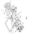
- Fig. 1 provides a perspective view of an embodiment of the device according to the invention.
- the shown device 1 for intermittently applying a liquid material onto a substrate is a device used in the industrial sector of book binding for applying a surface of foamed adhesive on a book's spine.
- the housing 2 has an internal fluid chamber 6 (not shown), which is in fluid communication with a discharge opening 12 when a rotatable valve member 14 is in a first position. While the rotatable valve member 14 is in the first position liquid material can flow from the internal fluid chamber through a discharge channel 10 or slot 10 opening 12 in order to be applied onto the substrate.
- the discharge channel 10 and the discharge opening 12 are part of a slot nozzle 8.
- the effective length and/or the effective width and/or the effective shape of the discharge opening 12 can be adjusted by means of adjustment means 22a, 22b.
- the adjustment means 22a, 22b are coupled with a hand wheel 23 through transmission means 25. By rotating the hand wheel 23 the device 1 can be configured to different book sizes and spine sizes, respectively.
- the rotatable valve member 14 is actuated by means of a rotating pneumatic drive 20.
- the rotary movement generated by the rotating pneumatic drive 20 is transferred to the rotatable valve member 14 through a gear box 21 having an adjustable transmission ratio.
- By rotating the rotatable valve member 14 from the first position into a second position the fluid communication between the internal fluid chamber and the discharge opening 12 is interrupted.
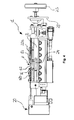
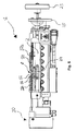
- Fig. 2 and Fig. 3 illustrate similar embodiments of a device according to the invention.
- the device shown in the perspective view of Fig. 2 features a pneumatic linear drive that causes the rotatable movement of the rotatable valve member 14. Therefore, transmission elements are used in order to convert the linear movement of the pneumatic linear drive into a rotational movement of the rotatable valve member 14.
- the perspective view of the embodiment of the device shown in Fig. 3 differs from the embodiment illustrated in Fig. 1 in that the gear box 21 is belt-driven such that the transmission ratio between the second driving device 20 and the rotatable valve member14 is fixed.
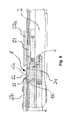
- the cross-sectional view in Fig. 4 shows a device without liquid material.
- the rotatable valve member 14 is a cylindrical rod and has a slot-shaped passageway 16.
- the slot-shaped passageway16 is capable of establishing fluid communication between the discharge opening 12 and the internal fluid chamber. The fluid communication is established while the rotatable valve member 14 is in the first position. In the first position of the rotatable valve member the liquid material is forced to flow from the internal fluid chamber through the discharge channel to the discharge opening 12 in order to be applied onto the substrate.
- a cylindrically shaped volume compensation channel 24 is disposed in the housing 2 of the device 1.
- Fig. 5 illustrates a cross-sectional view of a device that is coupled to a source of liquid material.
- fluid communication between volume compensation channel 24, internal fluid chamber and slot nozzle is established.
- the rotatable valve member 14 is partially disposed within the slot nozzle 8.
- FIG. 6 The cross-sectional view of Fig. 6 illustrates the direction of flow the liquid material from the volume compensation channel 24 through the internal fluid chamber 6, the discharge channel 10b, the slot-shaped passageway 16 of the rotatable valve member 14, the discharge channel 10a to the discharge opening 12 in greater detail.
- the discharge opening 12 and the discharge channels 10a, 10b are part of the slot nozzle 8.
- the rotatable valve member 14 is in the first position and therefore fluid communication between the internal fluid chamber 6 and the discharge opening 12 is established.
- Fig. 7 illustrates a cross-sectional side view of an embodiment of the device according to the invention.
- a first moveable member 4 is at least partially disposed within the internal fluid chamber 6.
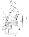
- the first moveable member 4 is capable of moving back and forth and thereby capable of moving between a first downstream position and a second upstream position. In the shown configuration the first moveable member 4 is in the first downstream position.
- the first moveable member 4 is actuated by a first driving device 18.
- the driving device allows for linear movement of the first moveable member 4 within the internal fluid chamber 6.
- the housing of the device 1 comprises a first part 2a and a second part 2b.
- the first moveable member 4 is disposed in the second part 2b of the housing.
- the rotatable valve member 14, the internal fluid chamber 6 and the volume compensation channel 24 are disposed partially in the first part 2a and partially in the second part 2b of the housing.
- the slot nozzle 8 is disposed between the first part 2a and the second part 2b of the housing. In the shown configuration the rotatable valve member 14 is in the first position, such that the discharge opening 12 is in fluid communication with the internal fluid chamber 6.
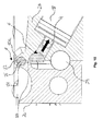
- FIG. 8 The detailed cross-sectional view of Fig. 8 illustrates that the slot-shaped passageway 16 of the rotatable valve member 14 is coupled with the discharge opening 12 by the discharge channel 10a.
- the slot-shaped passageway 16 of rotatable valve member 14 is connected to the internal fluid chamber 6 by the discharge channel 10b.
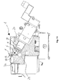
- Fig. 9 shows the first moveable member in the second upstream position.
- fluid material within the internal fluid chamber 6 is at least partially moved into an upstream direction.
- the movement of the fluid material in the upstream direction is caused by an enlargement of the volume of the internal fluid chamber through the movement of the first moveable member 4 from the first downstream position into the second upstream position.
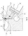
- Fig. 10 shows that the liquid material that has been in the discharge channel 10a between a discharge opening 12 and the rotatable valve member 14 (see Fig. 8 ) is entirely sucked into the slot-shaped passageway 16 of the rotatable valve member 14.
- Fig. 11 and Fig. 12 show the device 1 after the rotatable valve member is been rotated from the first position to the second position. Since the slot-shaped passageway of the rotatable valve member 14 is not aligned in-line with the discharge channel 10a, 10b, the fluid communication between the internal fluid chamber 6 and the discharge opening 12 is interrupted.
- Fig. 13 shows a schematic block diagram of an embodiment of the method according to the invention.
- the method makes use of the devices described above and/or in the claims.
- the first step of the illustrated step is forcing the liquid material flow from the internal fluid chamber through the discharge channel and the discharge opening 102.
- This step is followed by increasing the volume of the internal fluid chamber by a predetermined volume 104.
- Increasing the volume of the internal fluid chamber by a predetermined volume 104 can comprise the step moving a first moveable member, which is disposed at least partially within the internal fluid chamber from a first downstream position into a second upstream position 105a and/or the step moving the first moveable member at least partially out of the internal fluid chamber 105b.
- interrupting fluid communication between the internal fluid chamber and the discharge opening 106 is performed, wherein interrupting fluid communication between the internal fluid chamber and the discharge opening 106 can comprise rotating a rotatable valve member from a first position into a second position 107.
- This step is followed by the steps decreasing the volume of the internal fluid chamber by the predetermined volume 108, re-establishing fluid communication between the internal fluid chamber and the discharge opening 110 and adjusting the effective length and/or the effective width and/or the effective size of the discharge opening 112.
Landscapes
- Coating Apparatus (AREA)
Abstract
Description
- The present invention relates to a device and method for intermittently applying a liquid material, in particular foamed adhesive, onto a substrate.
- Such devices and methods are used in various industrial sectors to apply adhesives, sealants or other technical flowable materials onto a variety of different substrates such as films, packaging materials, machine parts or other work pieces.
- The device and the method according to the present invention especially relates to surface applications, wherein a closed layer of liquid material has to be applied onto the substrate for use in the manufacture of products. While the device and the method according to the present invention can be used in the manufacture of many different types of products one example is for use in the bookbinding industry to apply adhesive onto the spine of a book.
- The requirements to liquid materials are rising together with the quality expectations of the customers of the produced products. The improvements of the material's properties are associated by rising material prices. Thus, efficient production techniques are needed to compensate the rising material price.
- Therefore, various industry branches adapted their production equipment in order to use foamed materials, especially foamed adhesives. It has been found that foaming of adhesive does not lead to disadvantages in bonding quality for a variety of materials. The use of foamed adhesive leads to material savings and therefore to lower production costs.
- However, the use of foamed adhesives brings along a major disadvantage. The foamed materials tend to expend in volume and therefore a precise application of the foamed material onto the substrate is hampered. Especially realizing a proper cut-off in surface application cannot always be provided by means of the known application devices.
- In surface application devices foamed material is forced to flow through a slot shaped discharge channel or discharge slot in order to be discharged through a discharge opening onto a substrate. After the flow of foamed material has been interrupted by means of a closing (or valve) element, residual material remains between the closing element and the discharge opening. The expansion of the foamed material causes an improper after-flow on the application product and therefore an improper material cut-off is caused.
- Such a device for bookbinding applications having a slot nozzle for dispensing the foamed adhesive onto a book's spine is disclosed in
EP 1 419 900 B1 - The object of the present invention is therefore to provide a device and a method for intermittently applying a foamed material onto a substrate allowing for an improved material application, especially allowing for a proper material cut-off in surface applications.
- Thus, according to the invention, a device of the initially mentioned type is proposed, wherein the device comprises a housing having an internal fluid chamber, a first moveable member, which is at least partially moveable within the internal fluid chamber between a first downstream position and a second upstream position such that fluid within the fluid chamber is at least partially moved into an upstream direction when the first moveable member moves upstream, a slot nozzle having a discharge slot or channel and a discharge opening that communicates with the discharge channel, and a rotatable valve member that is rotatable between a first position, in which the internal fluid chamber is in fluid communication with the discharge opening, and a second position, in which the internal fluid chamber is not in fluid communication with the discharge opening.
- The invention makes use of the fact that foamed material cannot cause an improper material cut-off through material expansion while interrupting the flow of material, when the material located in the discharge slot or channel between the discharge opening and the rotatable valve member is sucked back before the rotatable valve member interrupts the flow of material. Since there is no expandable foamed material left between the discharge opening and the rotatable valve member while interrupting the flow of liquid material by means of the rotatable valve member, there is no or reduced risk that expanding material causes an undesired after-flow onto the application product.
- In a first preferred embodiment of the device according to the invention the rotatable valve member is a cylindrical rod and has at least one slot-shaped passageway and/or at least one cylindrically-shaped passageway. In the first position of the rotatable valve member the slot-shaped passageway and/or the cylindrically-shaped passageway is aligned in-line with the internal fluid chamber, such that fluid communication between the internal fluid chamber and the discharge opening is established. Through the cylindrically shaped rod a rotary valve function can be obtained while the cylindrical rod cooperates with a cylindrically shaped cavity in the housing. A lateral surface of the cylindrically shaped cavity functions as a valve seat for the rotatable valve member. By means of an elongate cylindrical rod having a slot shaped passageway a valve for a slot nozzle is provided which is capable of instantly interrupting and allowing for flow of a liquid material over the entire length of the slot or discharge channel, respectively, without displacing the fluid.
- In a second preferred embodiment of the device according to the invention the rotatable valve member is disposed adjacent to the discharge opening. Adjacent in the meaning of this invention has to be understood in the way that there is no other functional component between the discharge opening and the rotatable valve member, except the discharge channel or a part of the discharge channel that allows for fluid communication between the rotatable valve member and the discharge opening.
- It is further preferred that the rotatable valve member is disposed in a downstream direction relative to the first moveable member. This leads to the effect that the material located between the discharge opening and the rotatable valve member is sucked into or through the passageway of the rotatable valve member while the first moveable member moves from the first downstream position to the second upstream position.
- In another preferred embodiment of the device according to the invention the discharge channel is at least partially disposed between the discharge opening and the rotatable valve member. Further it is preferred that the device is adapted such that the volume released by the movement of the first moveable member from the first downstream position to the second upstream position equals the volume of the discharge channel between the discharge opening and the rotatable valve member. This leads to the effect, that a movement of the first moveable member from the first downstream position to the second upstream position completely empties the discharge channel between the discharge opening and the rotatable valve member. In an alternative embodiment the device according to the invention is adapted such that the volume released by the movement of the first moveable member from the first downstream position to the second upstream position is greater than the volume of the discharge channel between the discharge opening and the rotatable valve member.
- In another preferred embodiment of the device according to the invention a first pneumatically and/or electrically actuated driving device is coupled to the first moveable member to move the first moveable member back and forth. By moving the first moveable member back and forth the first downstream position as well as the second upstream position can be adjusted. The first pneumatically and/or electrically actuated driving device can comprise, for instance, a diaphragm pneumatic actuator, a pneumatic power cylinder, an electrical linear actuator, a rotationally drive having a transmission or a magnetic actuator. In an alternative embodiment the first driving device can also be hydraulically and/or mechanically actuated.
- In another preferred embodiment of the device according to the invention a second driving device is coupled with the rotatable valve member. It is preferred that the second driving device is a rotating pneumatic, hydraulic or electric drive or a pneumatic, hydraulic or electric linear drive.
- Another preferred embodiment of the device according to the invention comprises adjustment means adapted to adjust the effective length and/or the effective width and/or the effective shape of the discharge opening. By means of such adjustment means the device can be used to apply various sizes and/or shapes of surfaces onto substrates. In the bookbinding industry, for example, such adjustment means allow for applying foamed adhesive onto a variety of a different book sizes and/or shapes. The adjustment means are disposed adjacent to the discharge opening and can be moved such that a surface or surfaces of the adjustment means cover the discharge opening in a way preventing a flow of liquid material through the covered locations. The adjustment means may be moveably and detachably coupled with the housing. Guiding means as well as mounting means may be provided in order to precisely adjust the adjustment means and to fix the adjustment means at the desired location. The adjustment means further may have lateral recesses which are in fluid communication with a discharge opening. Such lateral recesses are used in the bookbinding process to extend the surface of discharged foamed adhesive over the edges of the book spine. This leads to an improved stability of the bound book as well as to an extended life span and increased durability of the binding.
- In another preferred embodiment of the device according to the invention a volume compensation channel and a moveable displacement element are provided, wherein the moveable displacement element is at least partially moveable within the volume compensation channel. The volume of the volume compensation channel is adaptable by the movement of the displacement element. Especially in combination with the use of adjustment means such a volume compensation is required in order to adjust for the right amount of liquid material to be dispensed.
- In another preferred embodiment of the device according to the invention the housing comprises at least a first part and a second part, wherein the first part and the second part are detachably coupled to each other, leading to various advantages. The maintenance and the repair of the device are considerably simplified. Broken and/or inoperative components may be easily replaced through a replacement of an entire part of the housing in which the broken or inoperative component is mounted. Cloggings and/or deposits which may have a negative effect on the application function or the application precision can be removed by easily disassembling the housing. Furthermore, the manufacturing process and therefore also the manufacturing costs can be reduced by a two-part or multi-part design of the housing. Complex passageway-structures enabling for fluid communication within the housing can be, for instance, realized as grooves on one side of a first housing part. A second housing part can be placed against the surface of the first housing part featuring the grooves in order to realize a complex system of passageways allowing for fluid communication.
- In another preferred embodiment of the device according to the invention the first moveable member is disposed in the second part of the housing and/or the rotatable valve member is disposed partially in the first part and partially in the second part of the housing and/or the internal fluid chamber is disposed partially in the first part and partially in the second part of the housing and/or the volume compensation channel is disposed partially in the first part and partially in the second part of the housing and/or the slot nozzle is disposed between the first part and the second part of the housing.
- In another preferred embodiment of the device according to the invention the rotatable valve member is adapted to rotate just in one rotational direction such that the rotation from the first position into the second position has the same rotational direction as the rotation from the second position into the first position. Since the first position and the second position of the rotatable valve member can be obtained by rotating the rotatable valve member in just one rotational direction, the cycle time can be adapted by modifying the rotational speed of the rotational valve member.
- The above cited object of the present invention is also solved by a method for intermittently applying a liquid material, in particular foamed adhesive, onto a substrate by means of a dispensing device having an internal fluid chamber and a slot nozzle. The slot nozzle has a discharge channel or slot and a discharge opening. The method comprises the steps forcing the liquid material to flow from the internal fluid chamber through the discharge channel and the discharge opening, increasing the volume of the internal fluid chamber by a predetermined volume, and interrupting fluid communication between the internal fluid chamber and the discharge opening after the volume of the internal fluid chamber is increased by the predetermined volume.
- Regarding the advantages of the method according to the invention it is referred to the advantages presented in reference to the device according to the invention.
- A first preferred embodiment of the method according to the invention comprises the steps decreasing the volume of the internal fluid chamber by the predetermined volume, and re-establishing fluid communication between the internal fluid chamber and the discharge opening, preferably before, during or after the volume of the internal fluid chamber is decreased by the predetermined volume.
- In a second preferred embodiment of the method according to the invention interrupting fluid communication between the internal fluid chamber and the discharge opening comprises the step rotating a rotatable valve member from a first position into a second position.
- In another preferred embodiment of the method according to the invention the predetermined volume is equal to or greater than a volume of the discharge channel between the discharge opening and the rotatable valve member. This leads to an entirely emptied discharge channel between the discharge opening and the rotatable valve member after the volume of the internal fluid chamber is increased and the fluid material is sucked in upstream direction.
- In another preferred embodiment of the method according to the invention increasing the volume of the internal fluid chamber by a predetermined volume comprises moving a first movable member being disposed at least partially within the internal fluid chamber from a first downstream position into a second upstream position and/or moving the first movable member at least partially out of the internal fluid chamber.
- Another embodiment of the method according to the invention comprises the step adjusting the effective length and/or the effective width and/or the effective size of the discharge opening.
- Yet another embodiment of the method according to the invention comprises the step applying adhesive onto a spine of a book. The quality of bookbindings can be improved considerably by using the method according to the invention. Furthermore, the cycle times can be increased and the required amount of adhesive per binding can be reduced.
- Below, the invention is described in greater detail with reference to preferred embodiments and to the drawings in the figures. The drawings show in:
- Fig. 1
- a perspective view of an embodiment of the device according to the invention;
- Fig. 2
- a perspective view of another embodiment of the device according to the invention;
- Fig. 3
- a perspective view of yet another embodiment of the device according to the invention;
- Fig. 4
- a front view of an embodiment of the device according to the invention showing parts of the device in a cross-sectional view;
- Fig. 5
- a front view of the embodiment illustrated in
Fig. 4 also showing parts of the device in a cross-sectional view; - Fig. 6
- a detailed cross-sectional view of parts of the embodiment illustrated in
Fig. 4 andFig. 5 ; - Fig. 7
- a cross-sectional side view of an embodiment of the device according to the invention;
- Fig. 8
- a detailed cross-sectional side view of the embodiment illustrated in
Fig. 7 ; - Fig. 9
- a cross-sectional side view of an embodiment of the device according to the invention;
- Fig. 10
- a detailed cross-sectional side view of the embodiment illustrated in
Fig. 9 ; - Fig. 11
- a cross-sectional side view of an embodiment of the device according to the invention;
- Fig. 12
- a detailed cross-sectional side view of the embodiment illustrated in
Fig. 11 , and - Fig. 13
- a schematic block diagram of an embodiment of the method according to the invention.
-
Fig. 1 provides a perspective view of an embodiment of the device according to the invention. The showndevice 1 for intermittently applying a liquid material onto a substrate is a device used in the industrial sector of book binding for applying a surface of foamed adhesive on a book's spine. Thehousing 2 has an internal fluid chamber 6 (not shown), which is in fluid communication with adischarge opening 12 when arotatable valve member 14 is in a first position. While therotatable valve member 14 is in the first position liquid material can flow from the internal fluid chamber through adischarge channel 10 orslot 10opening 12 in order to be applied onto the substrate. - The
discharge channel 10 and thedischarge opening 12 are part of aslot nozzle 8. The effective length and/or the effective width and/or the effective shape of thedischarge opening 12 can be adjusted by means of adjustment means 22a, 22b. The adjustment means 22a, 22b are coupled with ahand wheel 23 through transmission means 25. By rotating thehand wheel 23 thedevice 1 can be configured to different book sizes and spine sizes, respectively. Therotatable valve member 14 is actuated by means of a rotatingpneumatic drive 20. The rotary movement generated by the rotatingpneumatic drive 20 is transferred to therotatable valve member 14 through agear box 21 having an adjustable transmission ratio. By rotating therotatable valve member 14 from the first position into a second position the fluid communication between the internal fluid chamber and thedischarge opening 12 is interrupted. -
Fig. 2 andFig. 3 illustrate similar embodiments of a device according to the invention. The device shown in the perspective view ofFig. 2 features a pneumatic linear drive that causes the rotatable movement of therotatable valve member 14. Therefore, transmission elements are used in order to convert the linear movement of the pneumatic linear drive into a rotational movement of therotatable valve member 14. The perspective view of the embodiment of the device shown inFig. 3 differs from the embodiment illustrated inFig. 1 in that thegear box 21 is belt-driven such that the transmission ratio between thesecond driving device 20 and the rotatable valve member14 is fixed. - The cross-sectional view in
Fig. 4 shows a device without liquid material. Therotatable valve member 14 is a cylindrical rod and has a slot-shapedpassageway 16. The slot-shaped passageway16 is capable of establishing fluid communication between thedischarge opening 12 and the internal fluid chamber. The fluid communication is established while therotatable valve member 14 is in the first position. In the first position of the rotatable valve member the liquid material is forced to flow from the internal fluid chamber through the discharge channel to thedischarge opening 12 in order to be applied onto the substrate. A cylindrically shapedvolume compensation channel 24 is disposed in thehousing 2 of thedevice 1. -
Fig. 5 illustrates a cross-sectional view of a device that is coupled to a source of liquid material. In the illustrated configuration of thedevice 1, fluid communication betweenvolume compensation channel 24, internal fluid chamber and slot nozzle is established. Therotatable valve member 14 is partially disposed within theslot nozzle 8. - The cross-sectional view of
Fig. 6 illustrates the direction of flow the liquid material from thevolume compensation channel 24 through the internalfluid chamber 6, thedischarge channel 10b, the slot-shapedpassageway 16 of therotatable valve member 14, thedischarge channel 10a to thedischarge opening 12 in greater detail. Thedischarge opening 12 and thedischarge channels slot nozzle 8. In the shown configuration therotatable valve member 14 is in the first position and therefore fluid communication between the internalfluid chamber 6 and thedischarge opening 12 is established. -
Fig. 7 illustrates a cross-sectional side view of an embodiment of the device according to the invention. A firstmoveable member 4 is at least partially disposed within the internalfluid chamber 6. The firstmoveable member 4 is capable of moving back and forth and thereby capable of moving between a first downstream position and a second upstream position. In the shown configuration the firstmoveable member 4 is in the first downstream position. The firstmoveable member 4 is actuated by afirst driving device 18. The driving device allows for linear movement of the firstmoveable member 4 within the internalfluid chamber 6. It is also shown that the housing of thedevice 1 comprises a first part 2a and asecond part 2b. The firstmoveable member 4 is disposed in thesecond part 2b of the housing. Therotatable valve member 14, the internalfluid chamber 6 and thevolume compensation channel 24 are disposed partially in the first part 2a and partially in thesecond part 2b of the housing. Theslot nozzle 8 is disposed between the first part 2a and thesecond part 2b of the housing. In the shown configuration therotatable valve member 14 is in the first position, such that thedischarge opening 12 is in fluid communication with the internalfluid chamber 6. - The detailed cross-sectional view of
Fig. 8 illustrates that the slot-shapedpassageway 16 of therotatable valve member 14 is coupled with thedischarge opening 12 by thedischarge channel 10a. The slot-shapedpassageway 16 ofrotatable valve member 14 is connected to the internalfluid chamber 6 by thedischarge channel 10b. -
Fig. 9 shows the first moveable member in the second upstream position. Through the movement of the firstmoveable member 4 from the first downstream position to the second upstream position fluid material within the internalfluid chamber 6 is at least partially moved into an upstream direction. The movement of the fluid material in the upstream direction is caused by an enlargement of the volume of the internal fluid chamber through the movement of the firstmoveable member 4 from the first downstream position into the second upstream position. -
Fig. 10 shows that the liquid material that has been in thedischarge channel 10a between adischarge opening 12 and the rotatable valve member 14 (seeFig. 8 ) is entirely sucked into the slot-shapedpassageway 16 of therotatable valve member 14. -
Fig. 11 andFig. 12 show thedevice 1 after the rotatable valve member is been rotated from the first position to the second position. Since the slot-shaped passageway of therotatable valve member 14 is not aligned in-line with thedischarge channel fluid chamber 6 and thedischarge opening 12 is interrupted. -
Fig. 13 shows a schematic block diagram of an embodiment of the method according to the invention. Preferably, the method makes use of the devices described above and/or in the claims. - The first step of the illustrated step is forcing the liquid material flow from the internal fluid chamber through the discharge channel and the
discharge opening 102. This step is followed by increasing the volume of the internal fluid chamber by apredetermined volume 104. Increasing the volume of the internal fluid chamber by apredetermined volume 104 can comprise the step moving a first moveable member, which is disposed at least partially within the internal fluid chamber from a first downstream position into a secondupstream position 105a and/or the step moving the first moveable member at least partially out of theinternal fluid chamber 105b. Subsequently the step interrupting fluid communication between the internal fluid chamber and thedischarge opening 106 is performed, wherein interrupting fluid communication between the internal fluid chamber and thedischarge opening 106 can comprise rotating a rotatable valve member from a first position into asecond position 107. This step is followed by the steps decreasing the volume of the internal fluid chamber by thepredetermined volume 108, re-establishing fluid communication between the internal fluid chamber and thedischarge opening 110 and adjusting the effective length and/or the effective width and/or the effective size of thedischarge opening 112. -
- 1
- device
- 2
- housing
- 2a, 2b
- first and second part of the housing
- 4
- first movable member
- 6
- internal fluid chamber
- 8
- slot nozzle
- 10, 10a, 10b
- discharge channel or discharge slot
- 12
- discharge opening
- 14
- rotatable valve member
- 16
- slot-shaped passageway
- 18
- first driving device
- 20
- second driving device
- 21
- gear box
- 22a, 22b
- adjustment means
- 23
- hand wheel
- 24
- volume compensation channel
- 25
- transmission means
Claims (18)
- Device (1) for intermittently applying a liquid material, in particular foamed adhesive, onto a substrate, comprising:a housing (2) having an internal fluid chamber (6);a first movable member (4) being at least partially moveable within said internal fluid chamber (6) between a first downstream position and a second upstream position, such that fluid within said internal fluid chamber is at least partially moved into an upstream direction when said movable member moves upstream;a slot nozzle (8) having a discharge channel or slot (10, 10a, 10b) and a discharge opening (12) communicating with said discharge channel (10, 10a, 10b); anda rotatable valve member (14) being rotatable between a first position, in which said internal fluid chamber (6) being in fluid communication with said discharge opening (12), and a second position, in which said internal fluid chamber (6) not being in fluid communication with said discharge opening (12).
- Device (1) according to claim 1,
characterized in that said rotatable valve member (14) is a cylindrical rod and has at least one slot-shaped passageway (16) and/or at least one cylindrically-shaped passageway. - Device (1) according to claim 1 or 2,
characterized in that said rotatable valve member (14) is disposed adjacent to said discharge opening (12) and/or disposed in a downstream direction relative to said first movable member (4). - Device (1) according to one of the preceding claims,
characterized in that said discharge channel (10, 10a) is at least partially disposed between said discharge opening (12) and said rotatable valve member (14). - Device according to claim 1,
characterized in that said first movable member (4) is movable within a side channel communicating with said internal fluid chamber (6), preferably with a distribution channel for distributing fluid into said discharge slot (10, 10a, 10b) - Device (1) according to one of the preceding claims,
characterized in that a first pneumatically and/or electrically and/or hydraulically actuated driving device (18) is coupled to said first movable member (4) to move said first movable member (4) back and forth. - Device (1) according to one of the preceding claims,
characterized in that a second driving device (20) is coupled to said rotatable valve member (14), said second driving device (20) preferably being a rotating pneumatic, hydraulic and/or electric drive or a pneumatic, hydraulic and/or electric linear drive. - Device (1) according to one of the preceding claims,
characterized by adjustment means (22a, 22b) adapted to adjust the effective length and/or the effective width and/or the effective shape of said discharge opening (12). - Device (1) according to one of the preceding claims,
characterized by a volume compensation channel (24) and a movable displacement element at least partially moveable within said volume compensation channel (24), wherein the volume of said volume compensation channel (24) being adaptable by the movement of said displacement element. - Device (1) according to one of the preceding claims,
characterized in that said housing (2) comprises at least a first part (2a) and a second part (2b), wherein said first part (2a) and said second part (2b) being detachably coupled to each other or to a adapter element. - Device (1) according to claim 10,
characterized in that said first movable member (4) is disposed in said second part (2b) and/or said rotatable valve member (14) is disposed partially in said first part (2a) and partially in said second part (2b)
and/or said internal fluid chamber (6) is disposed partially in said first part (2a) and partially in said second part (2b)
and/or said volume compensation channel (24) is disposed partially in said first part (2a) and partially in said second part (2b)
and/or said slot nozzle (8) is disposed between said first part (2a) and said second part (2b). - Method (100) for intermittently applying a liquid material, in particular foamed adhesive, onto a substrate, using a dispensing device, preferably a dispensing device according to at least one at claims 1-11, having an internal fluid chamber and a slot nozzle, said slot nozzle having a discharge channel and a discharge opening, comprising the steps:forcing the liquid material to flow from said internal fluid chamber through said discharge channel and said discharge opening (102);increasing the volume of said internal fluid chamber by a predetermined volume (104); andinterrupting fluid communication between said internal fluid chamber and said discharge opening (106) after the volume of said internal fluid chamber being increased by the predetermined volume (104).
- Method (100) according to claim 12,
comprising the steps:decreasing the volume of said internal fluid chamber by said predetermined volume (108); andre-establishing fluid communication between said internal fluid chamber and said discharge opening (110). - Method (100) according to claim 12 or 13,
characterized in that interrupting fluid communication between said internal fluid chamber and said discharge opening (106) comprises:rotating a rotatable valve member from a first position into a second position (107). - Method (100) according to claim 14,
characterized in that said predetermined volume is equal to a volume of said discharge channel between said discharge opening and said rotatable valve member. - Method (100) according to one of the claims 12 to 15,
characterized in that increasing the volume of said internal fluid chamber by a predetermined volume (104) comprises:moving a first movable member that is disposed at least partially within said internal fluid chamber from a first downstream position into a second upstream position (105a) and/or moving said first movable member at least partially out of said internal fluid chamber (105b). - Method (100) according to one of the claims 12 to 16,
comprising the step:adjusting the effective length and/or the effective width and/or the effective size of said discharge opening (112). - Method (100) according to one of the claims 12 to 17,
comprising the step:applying adhesive onto a spine of a book.
Priority Applications (2)
| Application Number | Priority Date | Filing Date | Title |
|---|---|---|---|
| EP13198194.6A EP2886200B1 (en) | 2013-12-18 | 2013-12-18 | Device and method for intermittently applying a liquid material, in particular foamed adhesive onto a substrate |
| ES13198194T ES2834091T3 (en) | 2013-12-18 | 2013-12-18 | Device and method for the intermittent application of a liquid material, in particular foam adhesive, on a substrate |
Applications Claiming Priority (1)
| Application Number | Priority Date | Filing Date | Title |
|---|---|---|---|
| EP13198194.6A EP2886200B1 (en) | 2013-12-18 | 2013-12-18 | Device and method for intermittently applying a liquid material, in particular foamed adhesive onto a substrate |
Publications (2)
| Publication Number | Publication Date |
|---|---|
| EP2886200A1 true EP2886200A1 (en) | 2015-06-24 |
| EP2886200B1 EP2886200B1 (en) | 2020-09-23 |
Family
ID=49917453
Family Applications (1)
| Application Number | Title | Priority Date | Filing Date |
|---|---|---|---|
| EP13198194.6A Active EP2886200B1 (en) | 2013-12-18 | 2013-12-18 | Device and method for intermittently applying a liquid material, in particular foamed adhesive onto a substrate |
Country Status (2)
| Country | Link |
|---|---|
| EP (1) | EP2886200B1 (en) |
| ES (1) | ES2834091T3 (en) |
Cited By (5)
| Publication number | Priority date | Publication date | Assignee | Title |
|---|---|---|---|---|
| CN108187970A (en) * | 2018-01-23 | 2018-06-22 | 佛山市雅路斯工业设备有限公司 | A kind of valvular coating head of band |
| EP3476495A1 (en) * | 2017-10-26 | 2019-05-01 | RAMPF Holding GmbH & Co. KG | Slot die, coating arrangement comprising such a slot die, and cleaning device for such a slot die |
| EP3414021A4 (en) * | 2016-02-12 | 2019-10-16 | 3M Innovative Properties Company | FLAT SECTOR WITH ACTUALLY REGULATED COATING WIDTH |
| US11071997B2 (en) * | 2018-03-27 | 2021-07-27 | Robatech Ag | Device for applying a flowable substance to a substrate |
| CN114233911A (en) * | 2022-02-21 | 2022-03-25 | 常州铭赛机器人科技股份有限公司 | Quick-release quick-lock mechanism for flow channel |
Citations (8)
| Publication number | Priority date | Publication date | Assignee | Title |
|---|---|---|---|---|
| US20020053406A1 (en) * | 2000-07-10 | 2002-05-09 | Walter Baltensperger | Adhesive application station for printed products |
| JP2007253013A (en) * | 2006-03-22 | 2007-10-04 | Matsushita Electric Ind Co Ltd | Intermittent coating apparatus, battery electrode manufacturing method using the apparatus, and battery having battery electrode plate |
| EP1419900B1 (en) | 2002-10-30 | 2009-06-17 | Nordson Corporation | Apparatus for applying fluid |
| EP2319707A1 (en) * | 2009-11-04 | 2011-05-11 | Müller Martini Holding AG | Device for applying adhesive to the back of a book transported in a transport clamp of an adhesive binder device with a coating spray nozzle |
| US20110259265A1 (en) * | 2010-04-13 | 2011-10-27 | Nordson Corporation | Volume compensation for application heads with application width adjustment |
| EP2390011A2 (en) * | 2010-05-24 | 2011-11-30 | Samsung SDI Co., Ltd. | Active material coating apparatus and coating method |
| US20130277457A1 (en) * | 2012-04-20 | 2013-10-24 | Tdk Corporation | Application head and droplet applying apparatus |
| EP2684702A2 (en) * | 2012-07-10 | 2014-01-15 | Heidelberger Druckmaschinen AG | Device for applying adhesive and method for operating such a device |
Family Cites Families (3)
| Publication number | Priority date | Publication date | Assignee | Title |
|---|---|---|---|---|
| US7105203B1 (en) * | 1999-02-10 | 2006-09-12 | Mastsushita Electric Industrial Co., Ltd. | Intermittent coating apparatus and intermittent coating method |
| US20080166207A1 (en) * | 2005-03-30 | 2008-07-10 | Sogno Ag | Adhesive Application Station for Binding Printed Material |
| JP2006278183A (en) * | 2005-03-30 | 2006-10-12 | Sanyo Electric Co Ltd | Manufacturing method of battery electrode |
-
2013
- 2013-12-18 ES ES13198194T patent/ES2834091T3/en active Active
- 2013-12-18 EP EP13198194.6A patent/EP2886200B1/en active Active
Patent Citations (8)
| Publication number | Priority date | Publication date | Assignee | Title |
|---|---|---|---|---|
| US20020053406A1 (en) * | 2000-07-10 | 2002-05-09 | Walter Baltensperger | Adhesive application station for printed products |
| EP1419900B1 (en) | 2002-10-30 | 2009-06-17 | Nordson Corporation | Apparatus for applying fluid |
| JP2007253013A (en) * | 2006-03-22 | 2007-10-04 | Matsushita Electric Ind Co Ltd | Intermittent coating apparatus, battery electrode manufacturing method using the apparatus, and battery having battery electrode plate |
| EP2319707A1 (en) * | 2009-11-04 | 2011-05-11 | Müller Martini Holding AG | Device for applying adhesive to the back of a book transported in a transport clamp of an adhesive binder device with a coating spray nozzle |
| US20110259265A1 (en) * | 2010-04-13 | 2011-10-27 | Nordson Corporation | Volume compensation for application heads with application width adjustment |
| EP2390011A2 (en) * | 2010-05-24 | 2011-11-30 | Samsung SDI Co., Ltd. | Active material coating apparatus and coating method |
| US20130277457A1 (en) * | 2012-04-20 | 2013-10-24 | Tdk Corporation | Application head and droplet applying apparatus |
| EP2684702A2 (en) * | 2012-07-10 | 2014-01-15 | Heidelberger Druckmaschinen AG | Device for applying adhesive and method for operating such a device |
Cited By (8)
| Publication number | Priority date | Publication date | Assignee | Title |
|---|---|---|---|---|
| EP3414021A4 (en) * | 2016-02-12 | 2019-10-16 | 3M Innovative Properties Company | FLAT SECTOR WITH ACTUALLY REGULATED COATING WIDTH |
| US10888893B2 (en) | 2016-02-12 | 2021-01-12 | 3M Innovative Properties Company | Slot die with actively controlled coating width |
| EP3476495A1 (en) * | 2017-10-26 | 2019-05-01 | RAMPF Holding GmbH & Co. KG | Slot die, coating arrangement comprising such a slot die, and cleaning device for such a slot die |
| WO2019081560A1 (en) * | 2017-10-26 | 2019-05-02 | Rampf Holding Gmbh & Co. Kg | Slot die, coating arrangement comprising such a slot die, and cleaning device for such a slot die |
| CN108187970A (en) * | 2018-01-23 | 2018-06-22 | 佛山市雅路斯工业设备有限公司 | A kind of valvular coating head of band |
| CN108187970B (en) * | 2018-01-23 | 2024-06-21 | 佛山市雅路斯工业设备有限公司 | Coating head with valve |
| US11071997B2 (en) * | 2018-03-27 | 2021-07-27 | Robatech Ag | Device for applying a flowable substance to a substrate |
| CN114233911A (en) * | 2022-02-21 | 2022-03-25 | 常州铭赛机器人科技股份有限公司 | Quick-release quick-lock mechanism for flow channel |
Also Published As
| Publication number | Publication date |
|---|---|
| EP2886200B1 (en) | 2020-09-23 |
| ES2834091T3 (en) | 2021-06-16 |
Similar Documents
| Publication | Publication Date | Title |
|---|---|---|
| EP2886200B1 (en) | Device and method for intermittently applying a liquid material, in particular foamed adhesive onto a substrate | |
| CN104220260B (en) | Container is decorated | |
| US20080134966A1 (en) | Width adjustable multi slot gun | |
| US4369613A (en) | Apparatus for producing packages of two webs of varying lengths and widths | |
| EP2505507A1 (en) | Method for applying glue | |
| JP6330414B2 (en) | Coating head, coating apparatus and coating method | |
| US9114656B2 (en) | Method and device for exchanging an adhesive application roller | |
| US8800476B2 (en) | Volume compensation for application heads with application width adjustment | |
| US8708018B2 (en) | Arrangements and methods for applying a label to a moving object | |
| AU779194B2 (en) | Adhesive bandage pad module and method for making and applying adhesive bandage pads to a web | |
| WO2010149314A1 (en) | Joining device for joining two workpieces having either a pivotable stamp or a pivotable supporting table | |
| JP2016518280A (en) | Method and apparatus for operating a screen wheel filter | |
| EP1205257B1 (en) | Device for applying flowable adhesive onto a strip material moving relative to the device, particularly onto an edge rim for furniture | |
| EP1938905B1 (en) | A device having a slot nozzle unit for dispensing fluid | |
| EP1260277A2 (en) | A glue distribution unit in particular for machines which process wooden panels | |
| EP2316579A2 (en) | Apparatus for guiding a substrate and apparatus for dispensing a fluid | |
| CN104226548A (en) | An edge banding strip coating machine | |
| RS58407B1 (en) | Adjustable glue distribution device of an embossing-lamination group, relative group and adjusting method | |
| EP1980377B1 (en) | Apparatus and methods for profile wrapping laminates | |
| EP2629983B1 (en) | Adhesive delivering head for binding machines and machine incorporating the head | |
| US20110052827A1 (en) | Articulated Nozzle and Method of Applying a Strip of Viscoelastic Material Using Said Nozzle | |
| CN103406239B (en) | A gluing device | |
| CN108130812B (en) | Filter paper gluing forming machine | |
| CN105531108A (en) | Equipment for processing cardboard cut-offs | |
| CN100450642C (en) | Glue smearing device for coating machine |
Legal Events
| Date | Code | Title | Description |
|---|---|---|---|
| PUAI | Public reference made under article 153(3) epc to a published international application that has entered the european phase |
Free format text: ORIGINAL CODE: 0009012 |
|
| 17P | Request for examination filed |
Effective date: 20131218 |
|
| AK | Designated contracting states |
Kind code of ref document: A1 Designated state(s): AL AT BE BG CH CY CZ DE DK EE ES FI FR GB GR HR HU IE IS IT LI LT LU LV MC MK MT NL NO PL PT RO RS SE SI SK SM TR |
|
| AX | Request for extension of the european patent |
Extension state: BA ME |
|
| R17P | Request for examination filed (corrected) |
Effective date: 20160104 |
|
| RBV | Designated contracting states (corrected) |
Designated state(s): AL AT BE BG CH CY CZ DE DK EE ES FI FR GB GR HR HU IE IS IT LI LT LU LV MC MK MT NL NO PL PT RO RS SE SI SK SM TR |
|
| STAA | Information on the status of an ep patent application or granted ep patent |
Free format text: STATUS: EXAMINATION IS IN PROGRESS |
|
| 17Q | First examination report despatched |
Effective date: 20170731 |
|
| GRAP | Despatch of communication of intention to grant a patent |
Free format text: ORIGINAL CODE: EPIDOSNIGR1 |
|
| STAA | Information on the status of an ep patent application or granted ep patent |
Free format text: STATUS: GRANT OF PATENT IS INTENDED |
|
| INTG | Intention to grant announced |
Effective date: 20200417 |
|
| GRAS | Grant fee paid |
Free format text: ORIGINAL CODE: EPIDOSNIGR3 |
|
| GRAA | (expected) grant |
Free format text: ORIGINAL CODE: 0009210 |
|
| STAA | Information on the status of an ep patent application or granted ep patent |
Free format text: STATUS: THE PATENT HAS BEEN GRANTED |
|
| AK | Designated contracting states |
Kind code of ref document: B1 Designated state(s): AL AT BE BG CH CY CZ DE DK EE ES FI FR GB GR HR HU IE IS IT LI LT LU LV MC MK MT NL NO PL PT RO RS SE SI SK SM TR |
|
| REG | Reference to a national code |
Ref country code: GB Ref legal event code: FG4D |
|
| REG | Reference to a national code |
Ref country code: CH Ref legal event code: NV Representative=s name: WEINMANN ZIMMERLI, CH Ref country code: CH Ref legal event code: EP |
|
| REG | Reference to a national code |
Ref country code: DE Ref legal event code: R096 Ref document number: 602013072724 Country of ref document: DE |
|
| REG | Reference to a national code |
Ref country code: IE Ref legal event code: FG4D |
|
| REG | Reference to a national code |
Ref country code: AT Ref legal event code: REF Ref document number: 1315853 Country of ref document: AT Kind code of ref document: T Effective date: 20201015 |
|
| PG25 | Lapsed in a contracting state [announced via postgrant information from national office to epo] |
Ref country code: FI Free format text: LAPSE BECAUSE OF FAILURE TO SUBMIT A TRANSLATION OF THE DESCRIPTION OR TO PAY THE FEE WITHIN THE PRESCRIBED TIME-LIMIT Effective date: 20200923 Ref country code: NO Free format text: LAPSE BECAUSE OF FAILURE TO SUBMIT A TRANSLATION OF THE DESCRIPTION OR TO PAY THE FEE WITHIN THE PRESCRIBED TIME-LIMIT Effective date: 20201223 Ref country code: SE Free format text: LAPSE BECAUSE OF FAILURE TO SUBMIT A TRANSLATION OF THE DESCRIPTION OR TO PAY THE FEE WITHIN THE PRESCRIBED TIME-LIMIT Effective date: 20200923 Ref country code: GR Free format text: LAPSE BECAUSE OF FAILURE TO SUBMIT A TRANSLATION OF THE DESCRIPTION OR TO PAY THE FEE WITHIN THE PRESCRIBED TIME-LIMIT Effective date: 20201224 Ref country code: BG Free format text: LAPSE BECAUSE OF FAILURE TO SUBMIT A TRANSLATION OF THE DESCRIPTION OR TO PAY THE FEE WITHIN THE PRESCRIBED TIME-LIMIT Effective date: 20201223 Ref country code: HR Free format text: LAPSE BECAUSE OF FAILURE TO SUBMIT A TRANSLATION OF THE DESCRIPTION OR TO PAY THE FEE WITHIN THE PRESCRIBED TIME-LIMIT Effective date: 20200923 |
|
| REG | Reference to a national code |
Ref country code: AT Ref legal event code: MK05 Ref document number: 1315853 Country of ref document: AT Kind code of ref document: T Effective date: 20200923 |
|
| PG25 | Lapsed in a contracting state [announced via postgrant information from national office to epo] |
Ref country code: LV Free format text: LAPSE BECAUSE OF FAILURE TO SUBMIT A TRANSLATION OF THE DESCRIPTION OR TO PAY THE FEE WITHIN THE PRESCRIBED TIME-LIMIT Effective date: 20200923 Ref country code: RS Free format text: LAPSE BECAUSE OF FAILURE TO SUBMIT A TRANSLATION OF THE DESCRIPTION OR TO PAY THE FEE WITHIN THE PRESCRIBED TIME-LIMIT Effective date: 20200923 |
|
| REG | Reference to a national code |
Ref country code: NL Ref legal event code: MP Effective date: 20200923 |
|
| REG | Reference to a national code |
Ref country code: LT Ref legal event code: MG4D |
|
| PG25 | Lapsed in a contracting state [announced via postgrant information from national office to epo] |
Ref country code: PT Free format text: LAPSE BECAUSE OF FAILURE TO SUBMIT A TRANSLATION OF THE DESCRIPTION OR TO PAY THE FEE WITHIN THE PRESCRIBED TIME-LIMIT Effective date: 20210125 Ref country code: NL Free format text: LAPSE BECAUSE OF FAILURE TO SUBMIT A TRANSLATION OF THE DESCRIPTION OR TO PAY THE FEE WITHIN THE PRESCRIBED TIME-LIMIT Effective date: 20200923 Ref country code: LT Free format text: LAPSE BECAUSE OF FAILURE TO SUBMIT A TRANSLATION OF THE DESCRIPTION OR TO PAY THE FEE WITHIN THE PRESCRIBED TIME-LIMIT Effective date: 20200923 Ref country code: SM Free format text: LAPSE BECAUSE OF FAILURE TO SUBMIT A TRANSLATION OF THE DESCRIPTION OR TO PAY THE FEE WITHIN THE PRESCRIBED TIME-LIMIT Effective date: 20200923 Ref country code: RO Free format text: LAPSE BECAUSE OF FAILURE TO SUBMIT A TRANSLATION OF THE DESCRIPTION OR TO PAY THE FEE WITHIN THE PRESCRIBED TIME-LIMIT Effective date: 20200923 Ref country code: EE Free format text: LAPSE BECAUSE OF FAILURE TO SUBMIT A TRANSLATION OF THE DESCRIPTION OR TO PAY THE FEE WITHIN THE PRESCRIBED TIME-LIMIT Effective date: 20200923 Ref country code: CZ Free format text: LAPSE BECAUSE OF FAILURE TO SUBMIT A TRANSLATION OF THE DESCRIPTION OR TO PAY THE FEE WITHIN THE PRESCRIBED TIME-LIMIT Effective date: 20200923 |
|
| PG25 | Lapsed in a contracting state [announced via postgrant information from national office to epo] |
Ref country code: PL Free format text: LAPSE BECAUSE OF FAILURE TO SUBMIT A TRANSLATION OF THE DESCRIPTION OR TO PAY THE FEE WITHIN THE PRESCRIBED TIME-LIMIT Effective date: 20200923 Ref country code: IS Free format text: LAPSE BECAUSE OF FAILURE TO SUBMIT A TRANSLATION OF THE DESCRIPTION OR TO PAY THE FEE WITHIN THE PRESCRIBED TIME-LIMIT Effective date: 20210123 Ref country code: AT Free format text: LAPSE BECAUSE OF FAILURE TO SUBMIT A TRANSLATION OF THE DESCRIPTION OR TO PAY THE FEE WITHIN THE PRESCRIBED TIME-LIMIT Effective date: 20200923 Ref country code: AL Free format text: LAPSE BECAUSE OF FAILURE TO SUBMIT A TRANSLATION OF THE DESCRIPTION OR TO PAY THE FEE WITHIN THE PRESCRIBED TIME-LIMIT Effective date: 20200923 |
|
| REG | Reference to a national code |
Ref country code: ES Ref legal event code: FG2A Ref document number: 2834091 Country of ref document: ES Kind code of ref document: T3 Effective date: 20210616 |
|
| REG | Reference to a national code |
Ref country code: DE Ref legal event code: R097 Ref document number: 602013072724 Country of ref document: DE |
|
| PG25 | Lapsed in a contracting state [announced via postgrant information from national office to epo] |
Ref country code: SK Free format text: LAPSE BECAUSE OF FAILURE TO SUBMIT A TRANSLATION OF THE DESCRIPTION OR TO PAY THE FEE WITHIN THE PRESCRIBED TIME-LIMIT Effective date: 20200923 |
|
| PLBE | No opposition filed within time limit |
Free format text: ORIGINAL CODE: 0009261 |
|
| STAA | Information on the status of an ep patent application or granted ep patent |
Free format text: STATUS: NO OPPOSITION FILED WITHIN TIME LIMIT |
|
| GBPC | Gb: european patent ceased through non-payment of renewal fee |
Effective date: 20201223 |
|
| PG25 | Lapsed in a contracting state [announced via postgrant information from national office to epo] |
Ref country code: SI Free format text: LAPSE BECAUSE OF FAILURE TO SUBMIT A TRANSLATION OF THE DESCRIPTION OR TO PAY THE FEE WITHIN THE PRESCRIBED TIME-LIMIT Effective date: 20200923 Ref country code: DK Free format text: LAPSE BECAUSE OF FAILURE TO SUBMIT A TRANSLATION OF THE DESCRIPTION OR TO PAY THE FEE WITHIN THE PRESCRIBED TIME-LIMIT Effective date: 20200923 Ref country code: MC Free format text: LAPSE BECAUSE OF FAILURE TO SUBMIT A TRANSLATION OF THE DESCRIPTION OR TO PAY THE FEE WITHIN THE PRESCRIBED TIME-LIMIT Effective date: 20200923 |
|
| 26N | No opposition filed |
Effective date: 20210624 |
|
| REG | Reference to a national code |
Ref country code: BE Ref legal event code: MM Effective date: 20201231 |
|
| PG25 | Lapsed in a contracting state [announced via postgrant information from national office to epo] |
Ref country code: IE Free format text: LAPSE BECAUSE OF NON-PAYMENT OF DUE FEES Effective date: 20201218 Ref country code: LU Free format text: LAPSE BECAUSE OF NON-PAYMENT OF DUE FEES Effective date: 20201218 Ref country code: FR Free format text: LAPSE BECAUSE OF NON-PAYMENT OF DUE FEES Effective date: 20201231 |
|
| PG25 | Lapsed in a contracting state [announced via postgrant information from national office to epo] |
Ref country code: GB Free format text: LAPSE BECAUSE OF NON-PAYMENT OF DUE FEES Effective date: 20201223 |
|
| PG25 | Lapsed in a contracting state [announced via postgrant information from national office to epo] |
Ref country code: IS Free format text: LAPSE BECAUSE OF FAILURE TO SUBMIT A TRANSLATION OF THE DESCRIPTION OR TO PAY THE FEE WITHIN THE PRESCRIBED TIME-LIMIT Effective date: 20210123 Ref country code: TR Free format text: LAPSE BECAUSE OF FAILURE TO SUBMIT A TRANSLATION OF THE DESCRIPTION OR TO PAY THE FEE WITHIN THE PRESCRIBED TIME-LIMIT Effective date: 20200923 Ref country code: MT Free format text: LAPSE BECAUSE OF FAILURE TO SUBMIT A TRANSLATION OF THE DESCRIPTION OR TO PAY THE FEE WITHIN THE PRESCRIBED TIME-LIMIT Effective date: 20200923 Ref country code: CY Free format text: LAPSE BECAUSE OF FAILURE TO SUBMIT A TRANSLATION OF THE DESCRIPTION OR TO PAY THE FEE WITHIN THE PRESCRIBED TIME-LIMIT Effective date: 20200923 |
|
| PG25 | Lapsed in a contracting state [announced via postgrant information from national office to epo] |
Ref country code: MK Free format text: LAPSE BECAUSE OF FAILURE TO SUBMIT A TRANSLATION OF THE DESCRIPTION OR TO PAY THE FEE WITHIN THE PRESCRIBED TIME-LIMIT Effective date: 20200923 |
|
| PG25 | Lapsed in a contracting state [announced via postgrant information from national office to epo] |
Ref country code: BE Free format text: LAPSE BECAUSE OF NON-PAYMENT OF DUE FEES Effective date: 20201231 |
|
| P01 | Opt-out of the competence of the unified patent court (upc) registered |
Effective date: 20230527 |
|
| REG | Reference to a national code |
Ref country code: CH Ref legal event code: U11 Free format text: ST27 STATUS EVENT CODE: U-0-0-U10-U11 (AS PROVIDED BY THE NATIONAL OFFICE) Effective date: 20260101 |
|
| PGFP | Annual fee paid to national office [announced via postgrant information from national office to epo] |
Ref country code: DE Payment date: 20251211 Year of fee payment: 13 |
|
| PGFP | Annual fee paid to national office [announced via postgrant information from national office to epo] |
Ref country code: IT Payment date: 20251223 Year of fee payment: 13 |
|
| PGFP | Annual fee paid to national office [announced via postgrant information from national office to epo] |
Ref country code: ES Payment date: 20260130 Year of fee payment: 13 |
|
| PGFP | Annual fee paid to national office [announced via postgrant information from national office to epo] |
Ref country code: CH Payment date: 20260101 Year of fee payment: 13 |