EP2886049B1 - Messvorrichtung zur Messung der Bioimpedanz und/oder des Biopotenzials eines menschlichen oder tierischen Körpers - Google Patents
Messvorrichtung zur Messung der Bioimpedanz und/oder des Biopotenzials eines menschlichen oder tierischen Körpers Download PDFInfo
- Publication number
- EP2886049B1 EP2886049B1 EP13198776.0A EP13198776A EP2886049B1 EP 2886049 B1 EP2886049 B1 EP 2886049B1 EP 13198776 A EP13198776 A EP 13198776A EP 2886049 B1 EP2886049 B1 EP 2886049B1
- Authority
- EP
- European Patent Office
- Prior art keywords
- measuring
- voltage
- measurement device
- electrode
- potential
- Prior art date
- Legal status (The legal status is an assumption and is not a legal conclusion. Google has not performed a legal analysis and makes no representation as to the accuracy of the status listed.)
- Active
Links
Images


Classifications
-
- A—HUMAN NECESSITIES
- A61—MEDICAL OR VETERINARY SCIENCE; HYGIENE
- A61B—DIAGNOSIS; SURGERY; IDENTIFICATION
- A61B5/00—Measuring for diagnostic purposes; Identification of persons
- A61B5/24—Detecting, measuring or recording bioelectric or biomagnetic signals of the body or parts thereof
- A61B5/25—Bioelectric electrodes therefor
- A61B5/279—Bioelectric electrodes therefor specially adapted for particular uses
- A61B5/28—Bioelectric electrodes therefor specially adapted for particular uses for electrocardiography [ECG]
- A61B5/282—Holders for multiple electrodes
-
- A—HUMAN NECESSITIES
- A61—MEDICAL OR VETERINARY SCIENCE; HYGIENE
- A61B—DIAGNOSIS; SURGERY; IDENTIFICATION
- A61B5/00—Measuring for diagnostic purposes; Identification of persons
- A61B5/05—Detecting, measuring or recording for diagnosis by means of electric currents or magnetic fields; Measuring using microwaves or radio waves
- A61B5/053—Measuring electrical impedance or conductance of a portion of the body
-
- A—HUMAN NECESSITIES
- A61—MEDICAL OR VETERINARY SCIENCE; HYGIENE
- A61B—DIAGNOSIS; SURGERY; IDENTIFICATION
- A61B5/00—Measuring for diagnostic purposes; Identification of persons
- A61B5/24—Detecting, measuring or recording bioelectric or biomagnetic signals of the body or parts thereof
- A61B5/30—Input circuits therefor
- A61B5/307—Input circuits therefor specially adapted for particular uses
- A61B5/308—Input circuits therefor specially adapted for particular uses for electrocardiography [ECG]
-
- A—HUMAN NECESSITIES
- A61—MEDICAL OR VETERINARY SCIENCE; HYGIENE
- A61B—DIAGNOSIS; SURGERY; IDENTIFICATION
- A61B5/00—Measuring for diagnostic purposes; Identification of persons
- A61B5/68—Arrangements of detecting, measuring or recording means, e.g. sensors, in relation to patient
- A61B5/6801—Arrangements of detecting, measuring or recording means, e.g. sensors, in relation to patient specially adapted to be attached to or worn on the body surface
- A61B5/6802—Sensor mounted on worn items
- A61B5/6804—Garments; Clothes
- A61B5/6805—Vests, e.g. shirts or gowns
Definitions
- the present invention concerns a measurement device adapted to be worn on the body of a human or animal for measuring a bio-impedance and/or a bio-potential of the body.
- the most used method to measure biopotentials is to use electrodes made of a conductive material in contact with the skin.
- Each electrode is electrically connected to a centralized electronic unit amplifying and acquiring the potential signals.
- the cables are insulated and preferably shielded. They connect the electrodes with the centralized electronic unit in a star arrangement, where the centralized electronic unit is the common point to which all cables converge.
- the electrode can be made of a piece of Ag/Ag + Cl - interfaced to the skin with a gel. Such electrodes are most of the time disposable and passive.
- Electrodes include conductive material (metal, conductive rubber/silicone, conductive textile, conductive tape, etc.) in direct contact with the skin (dry electrodes), or interfaced to the skin with gel or liquid (water, saline, sweat, etc.).
- the electrodes may also physically perforate the skin to get a direct contact with the moisturized tissues under the dry upper layers of the skin.
- the measurement of bioimpedance or the electrical stimulation of a body part is performed the same way as the measurement of biopotentials, except that current is injected, at least at some electrodes.
- Another similar method allowing concealing the cables is to embed them in a garment. They can even be made of conductive textile in some situations.
- the electrodes are also part of the garment, which makes the donning and doffing as easy as to put on or take off a normal garment.
- Typical known products include a Holter's ECG recorder, where an insulated and shielded cable has to connect each electrode to the centralized electronic unit that amplifies and acquires the data. This results in a poor overall integration. In addition to the patient discomfort, such approach may suffer from accidental pulling of cable, which would make signal artifact if not totally interrupt the monitoring of the signals. All cables are connected to the centralized electronic unit in a star arrangement with the electronic unit being the convergence center.
- Caridiolnsight's product allows measuring 250 ECG leads with electrodes embedded in a patch.
- the connection still follows the same topology as the one of the Holter's recorder (centralized electronic unit not shown in the picture).
- a star arrangement with 250 connections makes the integration very difficult.
- Telzuit proposes a patch integrating the electrodes, the cables, and the centralized electronic unit.
- the topology is still the same as the one of the Holter's recorder, namely a star arrangement with the center in the centralized acquisition electronics.
- Weartech's smart shirt integrates textile electrodes.
- the electrical connections are made of conductive textile. They are not particularly shielded or insulated in this product, but this may degrade the signal quality especially in the presence of sweat or electromagnetic disturbances.
- the effect of these drawbacks is limited to an acceptable level in the targeted application (sports) by keeping the electrodes close to the centralized electronic unit.
- Camtech product consists of two electrodes.
- the centralized electronic unit is located on top of one of the electrodes.
- the system is limited to two electrodes. However, if it were extended to more electrodes, the connection would still be a start arrangement with all cables converging to the centralized electronic unit.
- the cable is conventional, i.e., insulated and shielded.
- the electrodes are standalone electrode sensors or more generally sensing and stimulating standalone electrode sensors.
- the product is made of only two electrode sensors (one reference standalone electrode sensor and one measuring/injecting standalone electrode sensor).
- the product could be extended to more measuring/injecting standalone electrode sensors.
- the electrodes would be connected to the same electrical connection in any chosen arrangement, i.e., not limited to a star arrangement with its center at a specific point.
- the electrical connection does no longer need to be shielded or insulated and can easily be made of conductive fabrics. Therefore, such system is usually made of a garment electrically connecting the sensors.
- Patent applications US20110001497 and EP2567657 by the present applicant disclose systems that require electrode sensors to have two contacts with the body. Such electrode sensors are named "bi-contact electrode sensors". They allow making systems that measure biopotentials with outstanding signal quality in the presence of electromagnetic disturbances. Moreover, thanks to the two contacts of the reference electrode sensor, the potential of the electrical connection (conductive garment) is close to the one inside the body. This allows the electrical connection to be not insulated. Bi-contact electrode sensors also allow measuring bioimpedance with only one electrical connection between the sensors, while being insensitive to the skin impedance as with the four-wire method which is the classical approach to measure bioimpedance. The four-wire method separates the injected current from the measurement of the resulting voltage by using two different sets of electrodes. In contrast with the approach disclosed in US20110001497 and EP2567657 , the four-wire method cannot connect all electrode sensors with only one electrical connection.
- a first limitation of the bi-contact approach disclosed in US20110001497 and EP2567657 when used with a single electrical connection is the sensitivity of its impedance variations which may be caused by varying tensions on the garment during motion, for instance.
- a single electrical connection is much easier to obtain than multiple ones. One reason is because it relaxes the insulation requirements between electrical connections. Another one is because the connecting of the electrical connection with the sensors is simpler. Finally, the manufacture is cheaper. However, as disclosed in EP2567657 , two electrical connections can solve the problem of sensitivity to impedance variations and allow one to recharge all electrode sensors while they remain in the garment. No solution has been proposed in the prior art to do the same with only a single electrical connection.
- bi-contact electrode sensors Another difficulty when using bi-contact electrode sensors comes from the distance between their two contacts that cannot be too small. Too-close contacts can result to the loss of the bi-contact effect. In such case, the two contacts behave like if they were short-circuited. Therefore, the size of the bi-contact electrode sensors cannot be reduced beyond a certain limit due to the minimum distance between the two contacts.
- bi-contact electrode sensors are relatively costly and difficult, especially to obtain hermetic sensors (desired due to the presence of moisture or sweat, or if one wants the sensors to be used by swimmers/divers or to be washable with the garment in the washing machine).
- hermetic sensors desired due to the presence of moisture or sweat, or if one wants the sensors to be used by swimmers/divers or to be washable with the garment in the washing machine.
- the necessity to alternate conductive materials (for the two contacts) with insulated material (between them) and possibly some sealing material also increases the risk to develop skin sensitivity (e.g., allergy) to one of the used materials.
- the present disclosure concerns a measurement device for measuring a bio-impedance and/or bio-potentials of a human or animal body and adapted to be worn on the body, comprising at least two electrode sensors; each of said at least two electrode sensors comprising a first electrical contact configured to be in contact with the skin of the body when the system is worn, and a second electrical contact; and a single electrical connector electrically connecting said at least two electrode sensors with each other via the second electrical contact; wherein an active device configured to cooperate with a subset of said at least two electrode sensors such that the potential of the electrical connector is substantially equal to a projected potential determined from the potential of the first electrical contact of each electrode sensor of said subset, when the measurement apparatus is worn.
- An advantage of the measurement device disclosed herein is that the electrical connector is at a potential close to the one in the user's body, despite any mains disturbance or any current injected by the measuring sensor electrodes.
- the high impedance of the skin becomes in this case an ally because it insulates the electrical connector from the user's body inside. Therefore, a garment on which the measuring device is attached when worn by the user can be simply made of conductive fabrics without the necessity to provide any particular insulation.
- Another advantage is that the measured bio-potentials are smaller and can more easily be within the input range of the electronic amplifiers. Moreover, inaccuracies of the amplifier gains or of the sample times have much less impact when the electrical connector is at a potential close to the one in the user's body.
- the electrical connector does not need to be shielded, nor insulated.
- One such single electrical connector is easy to manufacture. Sensitivity to impedance variations of electrical connection of garment can be drastically limited thanks to a connection method. Simultaneous recharging of bipolar electrode sensors is simple.
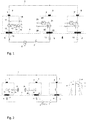
- Fig. 2 illustrate a measurement device for measuring a bio-potential of a human or animal body and destined to be worn on the body, according to an embodiment.
- the measurement device comprises a reference electrode sensor 1, a first measuring electrode sensor 2, and a second measuring electrode sensor 2'.
- Each of the electrode sensors 1, 2, 2' comprises a first electrical contact 5 destined to be in electrical contact with the skin of the body when the measurement device is worn on the body, and a second electrical contact 8.
- the measurement device further comprises a single electrical connector 3 electrically connecting the electrode sensors 1, 2, 2' with each other via the second electrical contact 8.
- the reference electrode sensor 1 comprises a voltage source 10 controllable by a controller 14.
- the first measuring electrode sensor 2 comprises a voltage measuring device 20.
- the voltage measuring device 20 is configured for measuring a voltage u1 between the first and second electrical contacts 5, 8 of the first measuring electrode sensor 2 when the measurement apparatus is worn.
- the measured voltage u1 can be inputted to the controller 14 controlling the voltage source 10 such that the voltage u1 between the first and second electrical contacts 5, 8 of the first measuring electrode sensor 2 is set to zero.
- the first measuring electrode sensor 2 has a substantially infinite impedance between the first and second electrical contacts 5, 8 (for a predetermined frequency band).
- the potential of the electrical connector 3 is substantially equal to the potential of the first electrical contact 5 of the first measuring electrode sensor 2, and thus to the potential (bio-potential 6) inside the body when the measurement device is worn.
- the measurement device comprises transmission means for transmitting the measured voltage u1 (signal 26 in Fig. 2 ) from the voltage measuring device 20 to an input 15 of the controller 14 that controls the voltage source 10.
- the transmission means comprises a wireless device 19, 29.
- the second measuring electrode sensor 2' can also comprise a voltage measuring device 20 such that a bio-potential 6 of the body can be determined by measuring a voltage u2 between the first and second electrical contacts 5, 8 of the second measuring electrode sensor 2', when the voltage u1 is set to zero and when the measurement apparatus is worn.
- the second measuring electrode sensor 2' can have a current source 21 set to zero current and thus corresponding to an open circuit.
- bio-potential is represented by a voltage source 6 and the skin impedance by the two impedances 13.
- the transmission means comprises means for encoding the voltage u1 using a high communication frequency band, for example of 2MHz, on the electrical connector 3, and for decoding the encoded measured voltage u1.
- the voltage u1 can be encoded in bits (digital encoding) as in any modern communication line.
- the controller can also be analogue and would typically be of the form -g/s, where s is the Laplace variable and g the gain of the integrator.
- the transmission means comprises a modulator 28 for modulating the measured voltage u1.
- the modulated voltage u1 can be demodulated in a demodulator 18 such that the modulated voltage u1 can be inputted in the input 15.
- Modulating the voltage u1 can be performed using a high frequency carrier such as a current generated at 2 MHz by a current source 21 comprised in the first measuring electrode sensor 2, using the modulator 28.
- the modulated current is then demodulated by the demodulator 18.
- the demodulator 18 can be a rectifier followed by a low-pass filter.
- the measuring device can comprise a plurality of reference electrode sensors 1, and a plurality of measuring electrode sensors 2, 2'; each electrode sensors 1, 2, 2' comprising the first and second electrical contacts 5, 8 and being electrically connected with each other with the electrical connector 3 via the second electrical contact 8.
- the voltage source 10 can be comprised in one or more reference electrode sensors 1. In such case, the voltage source 10 of each of the plurality of reference electrode sensors 1 can be set to the same value. Alternatively, the voltage source 10 of each of the plurality of reference electrode sensors 1 can comprise weighed values, for instance, the voltage source 10 of one of the plurality of reference electrode sensors 1 can be driven with a voltage X times the one of the other reference electrode sensors 1.
- the voltage measuring device 20 can be comprised in a subset of the plurality of measuring electrode sensors 2, 2', such that a plurality of voltages u1 can be measured from each measuring electrode sensor 2, 2' of the subset.
- the plurality of voltages u1 can be inputted to the controller 14 controlling the voltage source 10 for setting the potential of the electrical connector 3 substantially equal to a projected potential determined from the potential of the first electrical contact 5 of each electrode sensor 2, 2' of the subset.
- the projected potential can comprise the average of the plurality of the potentials of the first electrical contact 5 of each electrode sensor 2, 2' of the subset.
- the projected potential can comprise a maximum, a minimum, or a median of the plurality of the potentials.
- the subset of the plurality of measuring electrode sensors 2, 2' comprises all of the measuring electrode sensors 2, 2'.
- the bio-potential 6 of the body can be determined by measuring the voltage u2 between the first and second electrical contacts 5, 8 of the plurality of measuring electrode sensors 2, 2' comprising the voltage measuring device 20 and not used for measuring the voltage u1.
- the measuring electrode sensors 2, 2' used for measuring the voltage u2 can have a current source 21 set to zero current and thus corresponding to an open circuit.
- Fig. 1 illustrates a generalization of the measuring device of Fig. 2 showing that the measuring device can comprise a plurality of the measuring electrode sensors controller 24 and current source 21 can be comprised in any one of the measuring sensor electrodes 2, 2'.
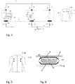
- Fig. 4 is a detailed view of one of the electrode sensors 1, 2, 2' according to an embodiment.
- the first electrical contact 5 is represented in contact with the skin 4 and the second electrical contact 8 is represented electrically contacting the electrical connector 3.
- the first and second electrical contacts 5, 8 can electrically contact the body 4 and the electrical connector 3, respectively, by galvanic or capacitive coupling.
- the electrode sensor 1, 2, 2' can further comprise a power supply 43 (for example a battery) or an energy harvesting device and an electronic circuit 44 that can be for instance an integrated circuit.
- the electronic circuit 44 typically picks up a physiological signal, such as for instance ECG.
- the electronic circuit 44 can also stimulate the body, such as for instance injecting a current for performing an impedance measurement.
- the electronic circuit 44 also allows the reference and/or measuring sensor electrode 1, 2, 2' to be isochronously synchronized and/or communicate with each other, for example using electromagnetic waves (wireless communication).
- the electrode sensor 1, 2, 2' can further comprise an insulator 41 for insulating the first and second electrical contacts 5, 8 from the power supply 43 and the electronic circuit 44.
- the electrode sensor 1, 2, 2' having the power supply 43 and the electronic circuit 44 can be considered as a standalone electrode sensor. Since the electrode sensors 1, 2, 2' comprise the two electrical contacts 5, 8, the power supply 43 and the electronic circuit 44, the electrode sensors 1, 2, 2' function as standalone bipolar electrode sensors.
- the measuring device is configured to be attached to a garment 50 so that when the garment is worn in the body, the first electrical contacts 5 are electrically contacting the skin 4.
- the garment can be electrically conductive such that, when the measuring device is attached to a garment 50, the second electrical contacts 8 electrically contact the garment 50, the latter having the role of the electrical connector 3.
- the garment can also comprise an electrically conductive portion in contact with the second electrical contacts 8 of the electrode sensors when the measuring device is attached to a garment 50.
- Fig. 5 represents the measuring device attached to an electrically conductive garment, wherein the measuring device comprises four electrode sensors, for example one reference electrode sensor 1 and three measuring electrode sensors 2.
- the measuring device comprises one reference electrode sensor 1 comprising the voltage source 10 controllable with the controller 14, and nine measuring electrode sensors 2, 2', 2", 2"'.
- the voltage measuring device 20 is included in a subset of three of the nine measuring electrode sensors 2, 2' and is configured for measuring a voltage uF, uR, uL between the first and second electrical contacts 5, 8 for each of measuring electrode sensors 2, 2' of the subset, when the measurement device is worn.
- the measuring device of Fig. 6 corresponds to a 12-lead ECG measuring system wherein the reference electrode sensor 1 takes the place of the guard electrode G, the three measuring electrode sensors 2, 2' plays the role of electrodes F, R, and L, respectively.
- the six other measuring electrode sensors 2", 2"' correspond to precordial leads V 1 to V 6 .
- the voltages uF, uR, uL can be inputted to the controller 14 controlling the voltage source 10 such as to set the potential of the electrical connector 3 substantially equal to a projected potential determined from the potential of the first electrical contact 5 of each electrode sensor 2, 2' of the subset of the three measuring electrode sensors 2, 2'.
- the projected potential can comprise the average, a maximum, a minimum, or a median of the plurality of the potentials of each electrode sensor 2, 2' of the subset.
- the potential of the electrical connector 3 thus corresponds to the Wilson's terminal of a 12-lead ECG measuring system.
- the six remaining precordial leads V 1 to V 6 can readily be measured by the measuring sensor electrodes 2", 2"' through their voltage u Vi .
- the voltages uF, uR, uL can be (signal 26) transmitted in real-time from each of the measuring electrode sensors 2, 2' of the subset to the controller input 1 wirelessly (via electromagnetic waves, such as Bluetooth or infrared), as described above.
- the measuring device further comprises a measuring electrode sensor 2" comprising a current source 21 configured for injecting an impedance current i3 passing in the reference electrode sensor 1.
- the measuring device of Fig. 7 allows for determining a bio-impedance 7 of the body as the quotient of the voltage u2 measured in the measuring electrode sensor 2', over the injected impedance current i3.
- the voltage u1 is set to zero by the voltage source 10 as described above.
- the measuring electrode sensors 2' can comprise a current source 21 set to zero current (corresponding to an open circuit as shown in Fig. 7 ).
- the impedance current i3 injected by the current source 21 of the measuring electrode sensor 2" can be used for electrical stimulation.
- the impedance current i3 can be sunk (i.e., negatively injected) with another measuring electrode sensor 2, 2' using its current source 21 with the same but opposite current.
- any of the measuring electrode sensors 2, 2', 2" can inject or sink any desired current patterns.
- several currents can be injected/sunk simultaneously on different channels, for instance at different frequencies or at different time slots.
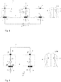
- the measuring device further comprises a reference electrode sensor 1 and two measuring electrode sensors 2, 2'.
- One of the measuring electrode sensors 2 comprises a current source 21 controllable by a controller 24.
- the current source 21 is configured for injecting a current 11 in the reference electrode sensor 1 when the measurement device is worn.
- the current 11 can be inputted to the controller 24 such that the current source 21 sets the current 11 to zero.
- the potential of the electrical connector 3 is substantially equal to a projected potential determined from the potential of the first electrical contact 5 of each electrode sensor of the subset comprising the electrode sensor 1.
- the bio-potential 6 of the body can be determined from the potential u2 measured at the other measuring sensor electrode 2' when the current 11 is set to zero.
- the measuring device of Fig. 8 can further comprise a measuring electrode sensor comprising a current source (not shown in Fig. 8 ) configured for injecting an impedance current (also not shown) passing in the measuring electrode sensor 2 as a result of the feedback loop setting the current 11 to zero.
- the bio-impedance 7 of the body can be determined as the quotient of the voltage u2 measured in the measuring electrode sensor 2', over the injected impedance current.
- the impedance current injected by the current source 21 of the measuring electrode sensor 2" can also be used for electrical stimulation.
- the measuring device comprises a measuring electrode sensor 2 and another measuring electrode sensor 2'.
- a first current i1 is injected by the current source 21 of the first measuring electrode sensor 2.
- a second current i2 is also injected using the current source 21 of the second measuring electrode sensor 2'.
- the second current i2 has substantially same magnitude than the first current i1 but has an opposed polarity.
- the potential of the electrical connector 3 is thus substantially equal to a projected potential determined from the potential of the first electrical contact 5 of each measuring electrode sensors 2, 2' when the measurement apparatus is worn.
- the bio-impedance of the body can be determined by dividing the potential difference u 1 -u 2 measured in the measuring electrode sensors 2 and 2' with the second current i2.
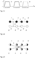
- the bio-potential 6 (or ECG) can be measured using the method according to any of the embodiments of Figs. 7 to 11 at a bio-potential frequency band comprised between about 1 to 1000 Hz.
- the bio-impedance can be measured using the method of Fig. 8 and the impedance current i3 being modulated in the impedance frequency band at about 50 kHz.
- the transmission means can be arranged for transmitting the measured voltage u1 at a communication frequency band being typically above 1 MHz.
- Fig. 11 represents the different frequency bands including the bio-potential frequency band 31, the impedance frequency band 32 and the communication frequency band 33.
- the communication frequency band 33 corresponds to the current 21 generated at 2 MHz for transmitting the first voltage u1 (as explained in Fig. 3 ).
- the impedance band 32 can be divided in several sub-bands, one for each impedance channel. In this case, not all frequency bands (or channels) have to follow the same method: a different method can be chosen for some of them if desired.
- the controllers 14, 24 comprised respectively in the reference sensor electrode 1 and the measurement electrode sensor 2 can have, for instance, their control law described by a transfer function equal to - g /(1-z -1 ), where z is the variable of the z-transform and g the gain of the resulting integrator.
- the controller 14, 24 can be physically in any electrode sensor 1, 2, distributed on several electrode sensors 1, 2, or even outside the measurement device. However, the preferred location for the controller 14 is in the reference electrode sensor 1 where a microcontroller executes the control law.
- the controllers 14, 24 can be single controllers as described above or two low-bandwidth controllers about a given frequency, one for the envelop of the cosine wave and one for the envelop of the sine wave (at the given frequency).
- Fig. 12 illustrates a particular arrangement of the reference electrode sensor 1 and measuring electrode sensors 2 according to an embodiment.
- the electrical connector comprises a first branch 3 electrically connecting the reference electrode sensor 1 with the measuring electrode sensors 2 in which a current is passing.
- the electrical connector comprises a second branch 3' electrically connecting the measuring electrode sensors 2' in which no current is passing.
- the electrical connector further comprises a third branch 3" electrically connecting the first and second branches 3, 3'.
- the third branch 3" is preferably a long and narrow electrical connector.
- the reference electrode sensor 1 and measuring electrode sensors 2 where a current is passed are represented by the filled circles, while the measuring electrode sensors 2 where no current passes are represented by the empty circles.
- Fig. 13 illustrates a particular arrangement of the reference sensor electrode 1 and measuring electrode sensor 2 according to another embodiment.
- each of the electrode sensor s 1, 2, 2' is electrically connected to a single common point (center of a star arrangement).
- the area of the single point should be minimized.
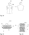
- Fig. 14 shows a method for recharging the electrode sensors 1, 2 without removing them from the garment.
- the first electrical contact 5 of any of the electrode sensors 1, 2 can be put in electrical contact with a conductive garment support device such as a manikin or flat hanger 60. Since the electrode sensors 1, 2 are in electrical contact with each other via the electrical connector 3, the connection with the hanger 60 will allow charging the battery 43 of any one of the electrode sensors 1, 2 when a voltage is applied between the electrical connector 3 and the manikin or flat hanger 60. Short circuit between the hanger 60 and the electrical connector 3 should be avoided, for example, by using an insulation layer on the garment, or on the hanger 60 except at the location of the electrode sensors 1, 2.
- Fig. 15 shows an electrode sensor 1, 2 comprising an attachment means 42, having the form of a stud button.
- the mechanical attachment 42 with the garment 50 also serves as electrical connector between the second electrical contact 8 and the electrical connector 3.
- Other attachment means can of course be used.
- Such attachment means can include, for instance, screw, rivet, hook-and-loop fastener (velcro), magnet, adhesive, etc.
- Fig. 16 illustrates an electrically conductive garment used as the electrical connection 3.
- the garment can comprises an insulating zone 51, for example made of insulated fabrics so as to have connector 3" linking the two zones 3 and 3' connecting the electrode sensors in which a current is passing and in which a current is not passing, respectively.
Landscapes
- Health & Medical Sciences (AREA)
- Life Sciences & Earth Sciences (AREA)
- Biomedical Technology (AREA)
- Molecular Biology (AREA)
- Veterinary Medicine (AREA)
- Biophysics (AREA)
- Pathology (AREA)
- Engineering & Computer Science (AREA)
- Public Health (AREA)
- Heart & Thoracic Surgery (AREA)
- Medical Informatics (AREA)
- Physics & Mathematics (AREA)
- Surgery (AREA)
- Animal Behavior & Ethology (AREA)
- General Health & Medical Sciences (AREA)
- Cardiology (AREA)
- Nuclear Medicine, Radiotherapy & Molecular Imaging (AREA)
- Radiology & Medical Imaging (AREA)
- Measurement And Recording Of Electrical Phenomena And Electrical Characteristics Of The Living Body (AREA)
Claims (19)
- Messvorrichtung zum Messen einer Bioimpedanz und / oder eines Biopotentials eines menschlichen oder tierischen Körpers und zum Tragen am Körper angepasst, umfassend: mindestens zwei Elektrodensensoren (1, 2, 2 '); wobei jeder der besagten mindestens zwei Elektrodensensoren (1, 2, 2 ') einen ersten einzelnen elektrischen Kontakt (5) umfasst, der nur so konfiguriert ist, dass er in elektrischem Kontakt mit der Haut (4) des Körpers steht, wenn das System getragen wird, und einen zweiten elektrischen Kontakt (8); und einen einzelnen elektrischen Verbinder (3), der die besagten mindestens zwei Elektrodensensoren (1, 2, 2 ') über den zweiten elektrischen Kontakt (8) elektrisch miteinander verbindet; worin eine aktive Vorrichtung (10, 21) konfiguriert ist, um mit einer Teilmenge der besagten mindestens zwei Elektrodensensoren (1, 2, 2 ') zusammenzuwirken, worin die aktive Vorrichtung (10, 21) konfiguriert ist, dem Potential des elektrischen Verbinders (3) entsprechende Spannung oder Strom an ein projiziertes Potential, das bestimmt wird aus dem Potential des ersten elektrischen Kontakts (5) jedes Elektrodensensors (1, 2, 2 ') einer Untergruppe der besagten mindestens zwei Elektrodensensoren (1, 2, 2 '), zu liefern, wenn die Messvorrichtung getragen wird.
- Messvorrichtung nach Anspruch 1, worin die besagten mindestens zwei Elektrodensensoren einen ersten Messelektrodensensor (2) und einen zweiten Messelektrodensensor (2 ') umfassen; und worin die besagte aktive Vorrichtung eine erste Stromquelle (21) umfasst, die im ersten Messelektrodensensor (2) enthalten und konfiguriert ist, um einen ersten Strom (i1) einzuspeisen, und eine weitere Stromquelle (21) umfasst, die im zweiten Messelektrodensensor (2 ') enthalten und konfiguriert ist, um einen zweiten Strom (i2) mit einem Wert im Wesentlichen gleich dem des ersten Stroms (i1) und entgegengesetzter Polarität einzuspeisen, so dass das Potential des elektrischen Verbinders (3) im Wesentlichen gleich einem projizierten Potential entspricht, das aus dem Potential des ersten elektrischen Kontaktes (5) jedes Messelektrodensensors (2, 2 ') bestimmt wird, wenn die Messeinrichtung getragen wird; und eine Potentialdifferenz (u1-u2) zwischen dem ersten und dem zweiten Messelektrodensensor (2, 2 ') in Kombination mit dem zweiten Strom (i2) kann zum Messen der Bioimpedanz des Körpers verwendet werden.
- Messvorrichtung nach Anspruch 1, worin die besagten mindestens zwei Elektrodensensoren mindestens einen Referenzelektrodensensor (1) und mindestens zwei Messelektrodensensoren (2, 2 ') umfassen; und worin die besagte aktive Vorrichtung eine Spannungsquelle (10) umfasst, die durch eine Steuerung (14) steuerbar und im besagten mindestens einen Referenzelektrodensensor (1) enthalten ist, und eine Spannungsmessvorrichtung (20), die in mindestens einem der Messelektrodensensoren (2, 2 ') enthalten; ist wobei die Spannungsmessvorrichtung (20) zum Messen einer Spannung (u1) zwischen den ersten und zweiten elektrischen Kontakten (5, 8) des besagten mindestens einen der Messelektrodensensoren (2, 2 ') eingerichtet ist, wenn die Messvorrichtung getragen wird; wobei die Spannungsquelle (10) und die Spannungsmessvorrichtung (20) so konfiguriert sind, dass sie mit einer Untergruppe zusammenwirken, welche die besagten mindestens zwei Messelektrodensensoren (2, 2 ') umfasst, wenn eine Projektion der gemessenen Spannungen (u1) in die Steuerung (14) für das Steuern der Spannungsquelle (10) eingegeben wird, um das Potential des elektrischen Verbinders (3) im wesentlichen gleich einem projizierten Potential zu setzen, das aus dem Potential des ersten elektrischen Kontakts (5) jedes Elektrodensensors (2, 2 ') der besagten Untergruppe bestimmt wird.
- Messvorrichtung nach Anspruch 3, zudem umfassend Übertragungsmittel zum Übertragen der gemessenen Spannung (u1) von der Spannungsmessvorrichtung (20) an einen Eingang (15) der Steuerung (14).
- Messvorrichtung nach Anspruch 4, worin das besagte Übertragungsmittel eine drahtlose Vorrichtung (19, 29) zum Übertragen der Spannung (u1) an den Eingang (15) umfasst.
- Messvorrichtung nach Anspruch 4, wobei das besagte Übertragungsmittel einen Modulator (28) zum Modulieren der Spannung (u1) und einen Demodulator (18) zum Demodulieren der mit einer Stromschleife (21, 11) übertragenen modulierten Spannung (u1) umfasst derart, dass die modulierte Spannung (u1) in den Eingang (15) eingegeben werden kann.
- Messvorrichtung nach Anspruch 6, worin das Übertragungsmittel ferner konfiguriert ist zum Übertragen der gemessenen Spannung (u1) durch einen modulierten Strom (21) mit einer Frequenz über 1 kHz.
- Messvorrichtung nach einem beliebigen der Ansprüche 3 bis 7, worin die besagten mindestens zwei Elektrodensensoren einen Referenzelektrodensensor (1) und neun Messelektrodensensoren (2, 2 ', 2 ") umfassen; wobei die Spannungsmessvorrichtung (20) in drei der neun Messelektrodensensoren (2, 2 ') enthalten ist und zum Messen einer ersten Spannung (uF, uR, uL) zwischen den ersten und zweiten elektrischen Kontakten (5, 8) für jeden der drei Messelektrodensensoren eingerichtet ist (2, 2 '), wenn die Messvorrichtung getragen wird, wobei die Spannungsquelle (10) und die Spannungsmessvorrichtung (20) so konfiguriert sind, dass sie mit der Untergruppe zusammenwirken, welche die besagten drei der neun Messelektrodensensoren (2, 2') umfasst, wenn die gemessene erste Spannung (uF, uR, uL) in die Steuerung (14) eingegeben wird, welche die Spannungsquelle (10) zum Einstellen des Potentials des elektrischen Verbinders (3) steuert, das im Wesentlichen einem projizierten Potential entspricht, das aus dem Potential des ersten elektrischer Kontaktes (5) jedes Elektrodensensors (2, 2 ') der besagten Teilmenge bestimmt wird.
- Messvorrichtung nach Anspruch 1, worin die besagten mindestens zwei Elektrodensensoren mindestens einen Referenzelektrodensensor (1) und mindestens zwei Messelektrodensensoren (2, 2 ') umfassen; worin die besagte aktive Vorrichtung eine Stromquelle (21) umfasst, die durch eine Steuerung (24) steuerbar und in mindestens einem der Messelektrodensensoren (2) enthalten ist, wobei die Stromquelle (21) zum Einspeisen eines Stroms (11) in besagten mindestens einen Referenzelektrodensensor (1) konfiguriert ist ,wenn die Messvorrichtung getragen wird; wobei die Stromquelle (21) konfiguriert ist um, mit der den besagten mindestens einen Referenzelektrodensensor (1) umfassenden Untergruppe zusammenzuwirken , wenn der Strom (11) in die Steuerung (24) eingegeben wird, welche die Stromquelle (21) zum Einstellen des Potentials des elektrischen Verbinders (3) steuert, das im wesentlichen einem projizierten Potential entspricht, das aus dem Potential des ersten elektrischen Kontakts (5) jedes Referenzelektrodensensors (1) der besagten Untergruppe bestimmt wird.
- Messvorrichtung nach einem beliebigen der Ansprüche 3 bis 9, worin die Messelektrodensensoren (2, 2 ') eine Spannungsmessvorrichtung (20) umfassen, die zum Messen einer Spannung (u2) zwischen dem ersten und dem zweiten elektrischen Kontakt (5, 8) des besagten Messelektrodensensors (2, 2 ') konfiguriert ist, wenn die Messvorrichtung getragen wird; und worin die Spannung (u2) zum Messen des Bio-Potentials (6) des Körpers verwendet werden kann.
- Messvorrichtung nach Anspruch 10, worin die Spannung (u2) eine Frequenz zwischen DC (0 Hz) und etwa 1000 Hz aufweist.
- Messvorrichtung nach Anspruch 10 oder 11, wobei die besagten mindestens zwei Elektrodensensoren zudem mindestens einen Messelektrodensensor (2 ") umfassen, der eine Stromquelle (21) umfasst, die zum Einspeisen eines Impedanzstroms (i3) konfiguriert ist; und worin der Quotient der Spannung (u2) über dem Impedanzstrom (i3) zur Bestimmung der Bioimpedanz des Körpers verwendet werden kann.
- Messvorrichtung nach Anspruch 12, wobei der Impedanzstrom (i3) eine Frequenz von etwa 50 kHz aufweist.
- Messvorrichtung nach einem beliebigen der Ansprüche 1 bis 13, worin das besagte projizierte Potenzial eines von einem Durchschnitt, einem Maximum, einem Minimum oder einem Mittelwert des Potentials des ersten elektrischen Kontakts (5) jedes Elektrodensensors (1, 2, 2 ') der besagten Untermenge umfasst.
- Messvorrichtung nach einem beliebigen der Ansprüche 1 bis 14, die so beschaffen ist, dass sie an einem vom Benutzer getragenen Kleidungsstück angebracht werden kann und einen elektrisch leitenden Abschnitt aufweist, so dass, wenn getragen, die zweiten elektrischen Kontakte (8) der Elektrodensensoren (1, 2, 2 ', 2 ") in elektrischem Kontakt mit dem leitfähigen Teil des Kleidungsstücks sind.
- Messvorrichtung nach einem beliebigen der Ansprüche 1 bis 15, worin jeder der Elektrodensensoren (1, 2, 2 ', 2 ") eine Stromversorgung (43) oder eine Energiegewinnungsvorrichtung umfasst.
- Messvorrichtung nach einem beliebigen der Ansprüche 1 bis 16, worin der elektrische Verbinder eine erste Verzweigung (3) umfasst, der die besagte mindestens eine Referenzsensorelektrode (1) elektrisch mit Messelektrodensensoren (2) verbindet, in denen ein Strom fliesst; eine zweite Verzweigung (3 '), der Messelektrodensensoren (2') elektrisch verbindet, in denen kein Strom fliesst; und eine dritte Verzweigung (3 "), welche die erste und die zweiten Verzweigung (3, 3 ') elektrisch verbindet.
- Messvorrichtung nach einem beliebigen der Ansprüche 1 bis 16, wobei jede der besagten mindestens einen Referenzsensorelektrode (1) und Messelektrodensensoren (2, 2 ') elektrisch mit einem einzigen gemeinsamen Punkt verbunden ist.
- Messvorrichtung nach Anspruch 15 und einem beliebigen der Ansprüche 16 bis 18, worin die Stromversorgung (43) eine Batterie ist, die wiederaufgeladen werden kann, wenn der erste elektrische Kontakt (5) irgendeiner der Elektrodensensoren (1, 2) elektrisch mit einer leitfähigen Kleidungsstückträgervorrichtung (60) verbunden ist und der zweite elektrische Kontakt (8) mit der elektrischen Verbindung 3.
Priority Applications (3)
| Application Number | Priority Date | Filing Date | Title |
|---|---|---|---|
| ES13198776.0T ES2690877T3 (es) | 2013-12-20 | 2013-12-20 | Dispositivo de medición para medir la bioimpedancia y/o un biopotencial de un cuerpo humano o animal |
| EP13198776.0A EP2886049B1 (de) | 2013-12-20 | 2013-12-20 | Messvorrichtung zur Messung der Bioimpedanz und/oder des Biopotenzials eines menschlichen oder tierischen Körpers |
| US14/576,925 US10105072B2 (en) | 2013-12-20 | 2014-12-19 | Measurement device for measuring bio-impedance and/or a bio-potential of a human or animal body |
Applications Claiming Priority (1)
| Application Number | Priority Date | Filing Date | Title |
|---|---|---|---|
| EP13198776.0A EP2886049B1 (de) | 2013-12-20 | 2013-12-20 | Messvorrichtung zur Messung der Bioimpedanz und/oder des Biopotenzials eines menschlichen oder tierischen Körpers |
Publications (2)
| Publication Number | Publication Date |
|---|---|
| EP2886049A1 EP2886049A1 (de) | 2015-06-24 |
| EP2886049B1 true EP2886049B1 (de) | 2018-08-22 |
Family
ID=49885022
Family Applications (1)
| Application Number | Title | Priority Date | Filing Date |
|---|---|---|---|
| EP13198776.0A Active EP2886049B1 (de) | 2013-12-20 | 2013-12-20 | Messvorrichtung zur Messung der Bioimpedanz und/oder des Biopotenzials eines menschlichen oder tierischen Körpers |
Country Status (3)
| Country | Link |
|---|---|
| US (1) | US10105072B2 (de) |
| EP (1) | EP2886049B1 (de) |
| ES (1) | ES2690877T3 (de) |
Families Citing this family (5)
| Publication number | Priority date | Publication date | Assignee | Title |
|---|---|---|---|---|
| AT518321B1 (de) | 2016-03-09 | 2019-03-15 | Dipl Ing Dr Techn Christoph Guger | Elektrodenhaube |
| US10925499B2 (en) | 2017-03-02 | 2021-02-23 | SP Global, Inc. | System and method for using integrated sensor arrays to measure and analyze multiple biosignatures in real time |
| US20210113108A1 (en) * | 2019-10-22 | 2021-04-22 | Sensesemi Technologies Private Limited | Method, system and device for generating electrocardiogram with fewer number of probes |
| EP3831289B1 (de) | 2019-12-05 | 2023-05-31 | CSEM Centre Suisse D'electronique Et De Microtechnique SA | Fernbetriebene kooperative sensorsystem |
| EP3928692A1 (de) * | 2020-06-26 | 2021-12-29 | CSEM Centre Suisse d'Electronique et de Microtechnique SA - Recherche et Développement | Sensorvorrichtung für potenzial- und impedanzmessungen |
Family Cites Families (6)
| Publication number | Priority date | Publication date | Assignee | Title |
|---|---|---|---|---|
| US6434420B1 (en) * | 2000-01-31 | 2002-08-13 | Integrated Biosensing Technologies | Biopotential electrode sensory component |
| AU2001256953A1 (en) * | 2000-01-31 | 2001-08-07 | Integrated Biosensing Technologies | Method and apparatus for biopotential sensing and stimulation |
| EP2101408B1 (de) | 2008-03-11 | 2012-05-16 | CSEM Centre Suisse d'Electronique et de Microtechnique SA - Recherche et Développement | Schwimmender Front-end-Verstärker und Einzeldrahtmessgeräte |
| WO2011020216A1 (zh) * | 2009-08-18 | 2011-02-24 | Yang Changming | 侦测生理机能及姿势状态的物品、方法和系统 |
| KR101736978B1 (ko) * | 2010-06-10 | 2017-05-17 | 삼성전자주식회사 | 생체 신호를 측정하는 장치 및 방법 |
| EP2567657B1 (de) | 2011-09-07 | 2019-11-27 | CSEM Centre Suisse d'Electronique et de Microtechnique SA - Recherche et Développement | Synchronisations- und Kommunikationsbus für Biopotenzial- und Bioimpedanzmesssysteme |
-
2013
- 2013-12-20 EP EP13198776.0A patent/EP2886049B1/de active Active
- 2013-12-20 ES ES13198776.0T patent/ES2690877T3/es active Active
-
2014
- 2014-12-19 US US14/576,925 patent/US10105072B2/en active Active
Non-Patent Citations (1)
| Title |
|---|
| None * |
Also Published As
| Publication number | Publication date |
|---|---|
| US10105072B2 (en) | 2018-10-23 |
| US20150173677A1 (en) | 2015-06-25 |
| ES2690877T3 (es) | 2018-11-22 |
| EP2886049A1 (de) | 2015-06-24 |
Similar Documents
| Publication | Publication Date | Title |
|---|---|---|
| US10105072B2 (en) | Measurement device for measuring bio-impedance and/or a bio-potential of a human or animal body | |
| US20160256066A1 (en) | Method and system to measure physiological signals or to electrically stimulate a body part | |
| US8315695B2 (en) | System and method for wireless generation of standard ECG leads and an ECG sensing unit therefor | |
| EP3324843B1 (de) | Tragbare vorrichtung und verfahren zur messung von elektromyografischen signalen eines benutzers | |
| EP2567657B1 (de) | Synchronisations- und Kommunikationsbus für Biopotenzial- und Bioimpedanzmesssysteme | |
| WO2015196298A1 (en) | A multi-parameter sensor system for measuring physiological signals | |
| US9445740B1 (en) | Patient signal sensing device | |
| JPH07508903A (ja) | 無線心電図検査システムおよび無線電極アセンブリ | |
| WO2013075388A1 (zh) | 一种侦测心跳或电极接触良好与否的物品、方法及系统 | |
| US20150201856A1 (en) | Electrode and measuring device for acquiring biomedical vital parameters | |
| KR101384761B1 (ko) | 호흡과 심전도의 동시 측정이 가능한 스포츠 브라 | |
| IL93389A (en) | A wireless system for recording heart function and supervision and assembling wireless electrodes for it | |
| US12478278B2 (en) | Sensor device for potential and impedance measurements | |
| US20190192051A1 (en) | Disposable sensor for neuromuscular transmission measurement | |
| ES2298740T3 (es) | Estructura integrada para detectar señales fisiologicas. | |
| KR102236976B1 (ko) | 탁상형 심전도 측정 시스템 | |
| US20250160714A1 (en) | Garment system with a dynamic electrode lead configuration | |
| KR102013646B1 (ko) | 두 전극 착용형 신호 감지 장치 및 착용형 신호 감지 장치의 동작 방법 | |
| US12251149B2 (en) | Remotely powered cooperative sensor device | |
| Chetelat et al. | Getting rid of the wires and connectors in physiological monitoring | |
| CN104720792A (zh) | 一种心电图测量设备 | |
| WO2024052977A1 (ja) | 生体信号計測システム | |
| US20170007141A1 (en) | Smart wireless electrode array | |
| CN117674753A (zh) | 一种肌电信号增益器 | |
| WO2018073847A1 (en) | Wearable device for acquiring electrocardiographic signals (ecg) signals |
Legal Events
| Date | Code | Title | Description |
|---|---|---|---|
| PUAI | Public reference made under article 153(3) epc to a published international application that has entered the european phase |
Free format text: ORIGINAL CODE: 0009012 |
|
| 17P | Request for examination filed |
Effective date: 20131220 |
|
| AK | Designated contracting states |
Kind code of ref document: A1 Designated state(s): AL AT BE BG CH CY CZ DE DK EE ES FI FR GB GR HR HU IE IS IT LI LT LU LV MC MK MT NL NO PL PT RO RS SE SI SK SM TR |
|
| AX | Request for extension of the european patent |
Extension state: BA ME |
|
| R17P | Request for examination filed (corrected) |
Effective date: 20151006 |
|
| RBV | Designated contracting states (corrected) |
Designated state(s): AL AT BE BG CH CY CZ DE DK EE ES FI FR GB GR HR HU IE IS IT LI LT LU LV MC MK MT NL NO PL PT RO RS SE SI SK SM TR |
|
| GRAP | Despatch of communication of intention to grant a patent |
Free format text: ORIGINAL CODE: EPIDOSNIGR1 |
|
| INTG | Intention to grant announced |
Effective date: 20180221 |
|
| GRAS | Grant fee paid |
Free format text: ORIGINAL CODE: EPIDOSNIGR3 |
|
| GRAA | (expected) grant |
Free format text: ORIGINAL CODE: 0009210 |
|
| AK | Designated contracting states |
Kind code of ref document: B1 Designated state(s): AL AT BE BG CH CY CZ DE DK EE ES FI FR GB GR HR HU IE IS IT LI LT LU LV MC MK MT NL NO PL PT RO RS SE SI SK SM TR |
|
| RAP1 | Party data changed (applicant data changed or rights of an application transferred) |
Owner name: CSEM CENTRE SUISSE D'ELECTRONIQUE ET DE MICROTECHN |
|
| REG | Reference to a national code |
Ref country code: GB Ref legal event code: FG4D |
|
| REG | Reference to a national code |
Ref country code: CH Ref legal event code: EP |
|
| REG | Reference to a national code |
Ref country code: AT Ref legal event code: REF Ref document number: 1031505 Country of ref document: AT Kind code of ref document: T Effective date: 20180915 |
|
| REG | Reference to a national code |
Ref country code: IE Ref legal event code: FG4D |
|
| REG | Reference to a national code |
Ref country code: DE Ref legal event code: R096 Ref document number: 602013042318 Country of ref document: DE |
|
| REG | Reference to a national code |
Ref country code: CH Ref legal event code: NV Representative=s name: NOVAGRAAF INTERNATIONAL SA, CH |
|
| REG | Reference to a national code |
Ref country code: ES Ref legal event code: FG2A Ref document number: 2690877 Country of ref document: ES Kind code of ref document: T3 Effective date: 20181122 |
|
| REG | Reference to a national code |
Ref country code: NL Ref legal event code: MP Effective date: 20180822 |
|
| REG | Reference to a national code |
Ref country code: LT Ref legal event code: MG4D |
|
| PG25 | Lapsed in a contracting state [announced via postgrant information from national office to epo] |
Ref country code: FI Free format text: LAPSE BECAUSE OF FAILURE TO SUBMIT A TRANSLATION OF THE DESCRIPTION OR TO PAY THE FEE WITHIN THE PRESCRIBED TIME-LIMIT Effective date: 20180822 Ref country code: GR Free format text: LAPSE BECAUSE OF FAILURE TO SUBMIT A TRANSLATION OF THE DESCRIPTION OR TO PAY THE FEE WITHIN THE PRESCRIBED TIME-LIMIT Effective date: 20181123 Ref country code: RS Free format text: LAPSE BECAUSE OF FAILURE TO SUBMIT A TRANSLATION OF THE DESCRIPTION OR TO PAY THE FEE WITHIN THE PRESCRIBED TIME-LIMIT Effective date: 20180822 Ref country code: IS Free format text: LAPSE BECAUSE OF FAILURE TO SUBMIT A TRANSLATION OF THE DESCRIPTION OR TO PAY THE FEE WITHIN THE PRESCRIBED TIME-LIMIT Effective date: 20181222 Ref country code: NO Free format text: LAPSE BECAUSE OF FAILURE TO SUBMIT A TRANSLATION OF THE DESCRIPTION OR TO PAY THE FEE WITHIN THE PRESCRIBED TIME-LIMIT Effective date: 20181122 Ref country code: SE Free format text: LAPSE BECAUSE OF FAILURE TO SUBMIT A TRANSLATION OF THE DESCRIPTION OR TO PAY THE FEE WITHIN THE PRESCRIBED TIME-LIMIT Effective date: 20180822 Ref country code: BG Free format text: LAPSE BECAUSE OF FAILURE TO SUBMIT A TRANSLATION OF THE DESCRIPTION OR TO PAY THE FEE WITHIN THE PRESCRIBED TIME-LIMIT Effective date: 20181122 Ref country code: NL Free format text: LAPSE BECAUSE OF FAILURE TO SUBMIT A TRANSLATION OF THE DESCRIPTION OR TO PAY THE FEE WITHIN THE PRESCRIBED TIME-LIMIT Effective date: 20180822 Ref country code: LT Free format text: LAPSE BECAUSE OF FAILURE TO SUBMIT A TRANSLATION OF THE DESCRIPTION OR TO PAY THE FEE WITHIN THE PRESCRIBED TIME-LIMIT Effective date: 20180822 |
|
| REG | Reference to a national code |
Ref country code: AT Ref legal event code: MK05 Ref document number: 1031505 Country of ref document: AT Kind code of ref document: T Effective date: 20180822 |
|
| PG25 | Lapsed in a contracting state [announced via postgrant information from national office to epo] |
Ref country code: HR Free format text: LAPSE BECAUSE OF FAILURE TO SUBMIT A TRANSLATION OF THE DESCRIPTION OR TO PAY THE FEE WITHIN THE PRESCRIBED TIME-LIMIT Effective date: 20180822 Ref country code: LV Free format text: LAPSE BECAUSE OF FAILURE TO SUBMIT A TRANSLATION OF THE DESCRIPTION OR TO PAY THE FEE WITHIN THE PRESCRIBED TIME-LIMIT Effective date: 20180822 Ref country code: AL Free format text: LAPSE BECAUSE OF FAILURE TO SUBMIT A TRANSLATION OF THE DESCRIPTION OR TO PAY THE FEE WITHIN THE PRESCRIBED TIME-LIMIT Effective date: 20180822 |
|
| PG25 | Lapsed in a contracting state [announced via postgrant information from national office to epo] |
Ref country code: CZ Free format text: LAPSE BECAUSE OF FAILURE TO SUBMIT A TRANSLATION OF THE DESCRIPTION OR TO PAY THE FEE WITHIN THE PRESCRIBED TIME-LIMIT Effective date: 20180822 Ref country code: RO Free format text: LAPSE BECAUSE OF FAILURE TO SUBMIT A TRANSLATION OF THE DESCRIPTION OR TO PAY THE FEE WITHIN THE PRESCRIBED TIME-LIMIT Effective date: 20180822 Ref country code: PL Free format text: LAPSE BECAUSE OF FAILURE TO SUBMIT A TRANSLATION OF THE DESCRIPTION OR TO PAY THE FEE WITHIN THE PRESCRIBED TIME-LIMIT Effective date: 20180822 Ref country code: EE Free format text: LAPSE BECAUSE OF FAILURE TO SUBMIT A TRANSLATION OF THE DESCRIPTION OR TO PAY THE FEE WITHIN THE PRESCRIBED TIME-LIMIT Effective date: 20180822 Ref country code: AT Free format text: LAPSE BECAUSE OF FAILURE TO SUBMIT A TRANSLATION OF THE DESCRIPTION OR TO PAY THE FEE WITHIN THE PRESCRIBED TIME-LIMIT Effective date: 20180822 |
|
| REG | Reference to a national code |
Ref country code: DE Ref legal event code: R097 Ref document number: 602013042318 Country of ref document: DE |
|
| PG25 | Lapsed in a contracting state [announced via postgrant information from national office to epo] |
Ref country code: SM Free format text: LAPSE BECAUSE OF FAILURE TO SUBMIT A TRANSLATION OF THE DESCRIPTION OR TO PAY THE FEE WITHIN THE PRESCRIBED TIME-LIMIT Effective date: 20180822 Ref country code: DK Free format text: LAPSE BECAUSE OF FAILURE TO SUBMIT A TRANSLATION OF THE DESCRIPTION OR TO PAY THE FEE WITHIN THE PRESCRIBED TIME-LIMIT Effective date: 20180822 Ref country code: SK Free format text: LAPSE BECAUSE OF FAILURE TO SUBMIT A TRANSLATION OF THE DESCRIPTION OR TO PAY THE FEE WITHIN THE PRESCRIBED TIME-LIMIT Effective date: 20180822 |
|
| PLBE | No opposition filed within time limit |
Free format text: ORIGINAL CODE: 0009261 |
|
| STAA | Information on the status of an ep patent application or granted ep patent |
Free format text: STATUS: NO OPPOSITION FILED WITHIN TIME LIMIT |
|
| 26N | No opposition filed |
Effective date: 20190523 |
|
| PG25 | Lapsed in a contracting state [announced via postgrant information from national office to epo] |
Ref country code: MC Free format text: LAPSE BECAUSE OF FAILURE TO SUBMIT A TRANSLATION OF THE DESCRIPTION OR TO PAY THE FEE WITHIN THE PRESCRIBED TIME-LIMIT Effective date: 20180822 Ref country code: SI Free format text: LAPSE BECAUSE OF FAILURE TO SUBMIT A TRANSLATION OF THE DESCRIPTION OR TO PAY THE FEE WITHIN THE PRESCRIBED TIME-LIMIT Effective date: 20180822 Ref country code: LU Free format text: LAPSE BECAUSE OF NON-PAYMENT OF DUE FEES Effective date: 20181220 |
|
| REG | Reference to a national code |
Ref country code: IE Ref legal event code: MM4A |
|
| REG | Reference to a national code |
Ref country code: BE Ref legal event code: MM Effective date: 20181231 |
|
| PG25 | Lapsed in a contracting state [announced via postgrant information from national office to epo] |
Ref country code: IE Free format text: LAPSE BECAUSE OF NON-PAYMENT OF DUE FEES Effective date: 20181220 |
|
| PG25 | Lapsed in a contracting state [announced via postgrant information from national office to epo] |
Ref country code: BE Free format text: LAPSE BECAUSE OF NON-PAYMENT OF DUE FEES Effective date: 20181231 |
|
| PG25 | Lapsed in a contracting state [announced via postgrant information from national office to epo] |
Ref country code: MT Free format text: LAPSE BECAUSE OF NON-PAYMENT OF DUE FEES Effective date: 20181220 |
|
| PG25 | Lapsed in a contracting state [announced via postgrant information from national office to epo] |
Ref country code: TR Free format text: LAPSE BECAUSE OF FAILURE TO SUBMIT A TRANSLATION OF THE DESCRIPTION OR TO PAY THE FEE WITHIN THE PRESCRIBED TIME-LIMIT Effective date: 20180822 |
|
| PGFP | Annual fee paid to national office [announced via postgrant information from national office to epo] |
Ref country code: IT Payment date: 20191227 Year of fee payment: 7 Ref country code: ES Payment date: 20200122 Year of fee payment: 7 |
|
| PG25 | Lapsed in a contracting state [announced via postgrant information from national office to epo] |
Ref country code: PT Free format text: LAPSE BECAUSE OF FAILURE TO SUBMIT A TRANSLATION OF THE DESCRIPTION OR TO PAY THE FEE WITHIN THE PRESCRIBED TIME-LIMIT Effective date: 20180822 |
|
| PG25 | Lapsed in a contracting state [announced via postgrant information from national office to epo] |
Ref country code: CY Free format text: LAPSE BECAUSE OF FAILURE TO SUBMIT A TRANSLATION OF THE DESCRIPTION OR TO PAY THE FEE WITHIN THE PRESCRIBED TIME-LIMIT Effective date: 20180822 Ref country code: MK Free format text: LAPSE BECAUSE OF NON-PAYMENT OF DUE FEES Effective date: 20180822 Ref country code: HU Free format text: LAPSE BECAUSE OF FAILURE TO SUBMIT A TRANSLATION OF THE DESCRIPTION OR TO PAY THE FEE WITHIN THE PRESCRIBED TIME-LIMIT; INVALID AB INITIO Effective date: 20131220 |
|
| REG | Reference to a national code |
Ref country code: DE Ref legal event code: R079 Ref document number: 602013042318 Country of ref document: DE Free format text: PREVIOUS MAIN CLASS: A61B0005042800 Ipc: A61B0005308000 |
|
| PG25 | Lapsed in a contracting state [announced via postgrant information from national office to epo] |
Ref country code: IT Free format text: LAPSE BECAUSE OF NON-PAYMENT OF DUE FEES Effective date: 20201220 |
|
| REG | Reference to a national code |
Ref country code: ES Ref legal event code: FD2A Effective date: 20220411 |
|
| PG25 | Lapsed in a contracting state [announced via postgrant information from national office to epo] |
Ref country code: ES Free format text: LAPSE BECAUSE OF NON-PAYMENT OF DUE FEES Effective date: 20201221 |
|
| PGFP | Annual fee paid to national office [announced via postgrant information from national office to epo] |
Ref country code: CH Payment date: 20250101 Year of fee payment: 12 |
|
| REG | Reference to a national code |
Ref country code: CH Ref legal event code: U11 Free format text: ST27 STATUS EVENT CODE: U-0-0-U10-U11 (AS PROVIDED BY THE NATIONAL OFFICE) Effective date: 20260101 |
|
| PGFP | Annual fee paid to national office [announced via postgrant information from national office to epo] |
Ref country code: GB Payment date: 20251230 Year of fee payment: 13 |
|
| PGFP | Annual fee paid to national office [announced via postgrant information from national office to epo] |
Ref country code: FR Payment date: 20251230 Year of fee payment: 13 |
|
| PGFP | Annual fee paid to national office [announced via postgrant information from national office to epo] |
Ref country code: DE Payment date: 20251222 Year of fee payment: 13 |