EP2885774B1 - Verbesserungen an oder im zusammenhang mit gesicherten systemen - Google Patents
Verbesserungen an oder im zusammenhang mit gesicherten systemen Download PDFInfo
- Publication number
- EP2885774B1 EP2885774B1 EP13869853.5A EP13869853A EP2885774B1 EP 2885774 B1 EP2885774 B1 EP 2885774B1 EP 13869853 A EP13869853 A EP 13869853A EP 2885774 B1 EP2885774 B1 EP 2885774B1
- Authority
- EP
- European Patent Office
- Prior art keywords
- electrically conductive
- resilient deformable
- deformable member
- conductive portion
- tampering
- Prior art date
- Legal status (The legal status is an assumption and is not a legal conclusion. Google has not performed a legal analysis and makes no representation as to the accuracy of the status listed.)
- Not-in-force
Links
- 238000001514 detection method Methods 0.000 claims description 25
- 238000000034 method Methods 0.000 claims description 17
- 229920001971 elastomer Polymers 0.000 claims description 7
- 239000000806 elastomer Substances 0.000 claims description 4
- 230000006835 compression Effects 0.000 claims 2
- 238000007906 compression Methods 0.000 claims 2
- 230000001939 inductive effect Effects 0.000 description 8
- 239000000463 material Substances 0.000 description 8
- 229910000859 α-Fe Inorganic materials 0.000 description 4
- XUIMIQQOPSSXEZ-UHFFFAOYSA-N Silicon Chemical compound [Si] XUIMIQQOPSSXEZ-UHFFFAOYSA-N 0.000 description 3
- 230000000694 effects Effects 0.000 description 3
- 238000005259 measurement Methods 0.000 description 3
- 229910052710 silicon Inorganic materials 0.000 description 3
- 239000010703 silicon Substances 0.000 description 3
- 230000009977 dual effect Effects 0.000 description 2
- 239000002184 metal Substances 0.000 description 2
- OKTJSMMVPCPJKN-UHFFFAOYSA-N Carbon Chemical compound [C] OKTJSMMVPCPJKN-UHFFFAOYSA-N 0.000 description 1
- 239000000853 adhesive Substances 0.000 description 1
- 230000001070 adhesive effect Effects 0.000 description 1
- 239000003990 capacitor Substances 0.000 description 1
- 229910052799 carbon Inorganic materials 0.000 description 1
- 238000010276 construction Methods 0.000 description 1
- 230000008878 coupling Effects 0.000 description 1
- 238000010168 coupling process Methods 0.000 description 1
- 238000005859 coupling reaction Methods 0.000 description 1
- 230000003247 decreasing effect Effects 0.000 description 1
- 238000010586 diagram Methods 0.000 description 1
- 238000005553 drilling Methods 0.000 description 1
- 230000003203 everyday effect Effects 0.000 description 1
- 238000003780 insertion Methods 0.000 description 1
- 230000037431 insertion Effects 0.000 description 1
- 238000009434 installation Methods 0.000 description 1
- 238000012423 maintenance Methods 0.000 description 1
- 238000004519 manufacturing process Methods 0.000 description 1
- 239000000615 nonconductor Substances 0.000 description 1
- 239000006187 pill Substances 0.000 description 1
- 239000012858 resilient material Substances 0.000 description 1
- 125000006850 spacer group Chemical group 0.000 description 1
- 229910001220 stainless steel Inorganic materials 0.000 description 1
- 239000010935 stainless steel Substances 0.000 description 1
- 239000000758 substrate Substances 0.000 description 1
- 230000001960 triggered effect Effects 0.000 description 1
Images


Classifications
-
- G—PHYSICS
- G08—SIGNALLING
- G08B—SIGNALLING OR CALLING SYSTEMS; ORDER TELEGRAPHS; ALARM SYSTEMS
- G08B13/00—Burglar, theft or intruder alarms
- G08B13/02—Mechanical actuation
- G08B13/06—Mechanical actuation by tampering with fastening
-
- F—MECHANICAL ENGINEERING; LIGHTING; HEATING; WEAPONS; BLASTING
- F16—ENGINEERING ELEMENTS AND UNITS; GENERAL MEASURES FOR PRODUCING AND MAINTAINING EFFECTIVE FUNCTIONING OF MACHINES OR INSTALLATIONS; THERMAL INSULATION IN GENERAL
- F16B—DEVICES FOR FASTENING OR SECURING CONSTRUCTIONAL ELEMENTS OR MACHINE PARTS TOGETHER, e.g. NAILS, BOLTS, CIRCLIPS, CLAMPS, CLIPS OR WEDGES; JOINTS OR JOINTING
- F16B31/00—Screwed connections specially modified in view of tensile load; Break-bolts
- F16B31/02—Screwed connections specially modified in view of tensile load; Break-bolts for indicating the attainment of a particular tensile load or limiting tensile load
- F16B31/028—Screwed connections specially modified in view of tensile load; Break-bolts for indicating the attainment of a particular tensile load or limiting tensile load with a load-indicating washer or washer assembly
-
- F—MECHANICAL ENGINEERING; LIGHTING; HEATING; WEAPONS; BLASTING
- F16—ENGINEERING ELEMENTS AND UNITS; GENERAL MEASURES FOR PRODUCING AND MAINTAINING EFFECTIVE FUNCTIONING OF MACHINES OR INSTALLATIONS; THERMAL INSULATION IN GENERAL
- F16B—DEVICES FOR FASTENING OR SECURING CONSTRUCTIONAL ELEMENTS OR MACHINE PARTS TOGETHER, e.g. NAILS, BOLTS, CIRCLIPS, CLAMPS, CLIPS OR WEDGES; JOINTS OR JOINTING
- F16B41/00—Measures against loss of bolts, nuts, or pins; Measures against unauthorised operation of bolts, nuts or pins
- F16B41/005—Measures against unauthorised operation of bolts, nuts or pins
-
- G—PHYSICS
- G01—MEASURING; TESTING
- G01R—MEASURING ELECTRIC VARIABLES; MEASURING MAGNETIC VARIABLES
- G01R27/00—Arrangements for measuring resistance, reactance, impedance, or electric characteristics derived therefrom
- G01R27/02—Measuring real or complex resistance, reactance, impedance, or other two-pole characteristics derived therefrom, e.g. time constant
-
- G—PHYSICS
- G08—SIGNALLING
- G08B—SIGNALLING OR CALLING SYSTEMS; ORDER TELEGRAPHS; ALARM SYSTEMS
- G08B13/00—Burglar, theft or intruder alarms
- G08B13/02—Mechanical actuation
- G08B13/14—Mechanical actuation by lifting or attempted removal of hand-portable articles
- G08B13/149—Mechanical actuation by lifting or attempted removal of hand-portable articles with electric, magnetic, capacitive switch actuation
Definitions
- the present invention relates to tamper evident systems.
- the present invention is directed to tamper evident devices, their methods of use and manufacture to detect unauthorised tampering of fasteners, or devices held in place by fasteners.
- mission critical for example traffic light systems
- high value for example currency vending machines
- EFTPOS payment machines for example EFTPOS payment machines
- Tamper detection is also valuable for a computer or electronics suite. For example, it may allow an alert to occur if a person attempts to gain access to the internal units or remove device components. Equipment that has key pads, security card readers, or credit card and EFTPOS machine readers can often be tampered with to remove and replace the content with the tamperer's own equipment. This, for example, would direct funds to the tamperer's account instead of the correct account. Other tampering may involve insertion of information scanning systems to allow capture of a user's information, for example security keypad entry, credit card or EFTPOS card details.
- WO03/005334 and US5,488,206 each disclose a 'joystick' user interface arrangement for manipulation by a user.
- US2006/0048582 discloses a load cell arrangement for detecting a person sitting in a seat in a vehicle.
- US2002/0014962 describes a tamper resistant enclosure for protecting an electronic device.
- the enclosure includes an external cover and an internal cover.
- Four screws secure the internal cover to the device and the external cover by means of standoffs.
- a washer is interposed between the device and the standoff.
- the device has a dielectric substrate with a metal pad around each hole for ensuring the electrical connection to ground through the washer, the standoff and the conductive body of the external cover.
- WO 2006/092591 shows an anti-tamper device for detecting relative movement between a part having a stud clamped to a mounting by a nut.
- the present invention consists in a tamper detection element , as claimed.
- the present invention consists in a method of detecting unauthorised tampering with a fastener or a device held to a first member by the fastener, as claimed.
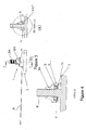
- the tamper detection element 1 is shown in Figures 1 and 2 held to a first member 2 by a second member 8.
- the second member 8 is comprised of a threaded fastener 8A and a nut 8B engaged thereon.
- the element 1 can perform its task, and in the preferred embodiment it is sandwiched between a first member and a second member.
- a fastener is just one example of how it can be held in place, other methods can also be used, such as sandwiching between a first member and a second member which may be a planar surface such as a wall or door.
- the fastener 8A and nut 8B in Figures 3 and 4 may not be present, but rather the second member 8 is a surface of a cabinet or door sandwiching the element 1 in place.
- the element 1 consists of a resilient deformable member 3 which when the element is secured in place is held down against or in proximity to a contact sensing member 5.
- the resilient deformable member 3 is made from an elastomer such as silicon or rubber (natural or synthetic).
- a housing 9 to at least in part contain the members 3 and 5.
- the element 1 relies on change in pressure on the element to vary the impedance of the element.
- the relationship between the resilient deformable member 3 and the contact sensing member 5 will determine if a tamper is occurring.
- the tamper detection may comprise an electrical circuit connected to tamper detection element 1.
- the electrical circuit may measure the impedance, or its variation, of the circuit, for example of the resilient deformable member 3 and the contact sensing members.
- the impedance measured may comprise one of, or a combination of, resistive, capacitive or inductive components.
- the resilient deformable member 3 has a first electrically conductive portion 4 as seen in Figure 4 .
- This in the assembly shown is on the lower part of the resilient deformable member 3.
- the first electrically conductive portion may be on the upper or a middle part of the resilient deformable member, for example in use as a capacitive circuit.
- the first electrically conductive portion may be adjacent, and not part of the resilient deformable member. When the first conductive portion and the resilient deformable member are adjacent there may be an air gap (for example for capacitive sensing), spacer or other element/s placed between them.
- the first electrically conductive portion 4 may be a lower portion of the member 3 that is conductive.
- the electrically conductive portion 4 may contact the contact sensing member 5, for example on a second electrically conductive portion 6 as shown in Figure 6 or the portion and member may be separated by another element, such as an electrical insulator (for example when capacitive or inductive sensing is used).
- an electrical insulator for example when capacitive or inductive sensing is used.
- the material is an elastomer it may be doped, for example with carbon to make that lower portion conductive to therefore form the first conductive portion 4.
- it When it is the lower form and in contact with the second conductive portion 6 it may be used for resistive sensing of tampering.
- it When it is on the upper portion (whether unitary or separate) then it may be part of a capacitive sensing or inductive sensing.
- the material may be silicon doped with ferrite to act as, for instance, a magnetic core.
- the deformable member 3 may act as a way to exert pressure (and therefore vary it on tampering) and other electrical components to form the impedance circuit may be located against it.
- the upper portion and remainder of the member 3 that is not in contact with the contact sensing member 5 is not conductive. This may insulate the circuit from the effects of any wear of the housing 9.
- the member 3 is an endless member, but can be formed as necessary to fit the desired application.
- the contact sensing member 5 is shown in Figure 2 (and Figure 6 ) has at least one second electrically conductive portion 6 at the head 14.
- it has two such portions a second 6 and third 7 (or more) on a top surface, which are diametrically opposed, to allow for example electrical contact with the first conductive portion 4 when there is resistive sensing.
- the portions may be below the surface (for example when physical electrical contact with deformable member 3 is not required, for example in capacitive or inductive sensing).
- the portions may cover conforms to the shape of the resilient deformable member 3 it locates against but is not necessarily so. Therefore in the example shown in Figure 2 the head 14 is also shown as an endless member.
- the head 14 of the contact sensing member 5 where it locates with the resilient deformable member 3 may be shaped as needed for the intended application.
- the tail 15 extends from the head 14 of the contact sensing member 5 as shown in Figure 2 .
- the tail 15 contains circuit traces 16 which go to one each to the second electrically conductive portion 6 and third electrically conductive portion 7. Traces 16 then connect out and at the end of the tail 15 for connection to sensing equipment 17.
- the sensing equipment can be locally contained within the piece of equipment 12 which is being protected, and in addition may send signals locally for alerts or may send them remotely from the piece of equipment 12.
- the sensing equipment 17 may send a local alert for example a flashing light or otherwise, and may also or instead send a signal to a remote sensing station to sound an alarm to indicate tampering with the equipment.
- the contact sensing member or members may comprise additional electrical contacts.
- the electrical contacts may be provided on a backing layer.
- the backing layer may provide support or encourage the contacts into appropriate positions. In a preferred embodiment these contacts will comprise a part of a printed wire board.
- the printed wire board may be rigid, flexible or comprise both rigid and flexible sections. In the following description it should be realised that reference to a printed wire board or other backing layer material encompasses a broad range of backing layers, flexible, rigid or otherwise.
- the contact sensing member 5 is a flexible printed circuit with exposed conductive portions forming the second electrically conductive portion 6 and third electrically conductive portion 7. Some, or all, of the areas of the flexible printed circuit may also be reinforced. This may help to insert it into equipment and/or for mounting purposes.
- a rigid printed wiring board may be used, for instance to provide a more resilient member.
- the total impedance of the circuit formed in conjunction with the first resilient deformable member 3 when in contact with the contact sensing member 5 is within a known range and any deviation may cause an alarm.
- the impedance of an immediate physical contact between a resilient deformable member 3 having a first electrically conductive portion 4 against at least the second electrically conductive portion 6 and preferably third electrically conductive portion 7 is within a known range, and any deviation again, may cause an alarm.
- the impedance of an electrical relationship between a first electrically conductive portion 4 adjacent or on said resilient deformable member 3 and a second electrically conductive portion 6 and possibly a third electrically conductive portion 7 is within a known range, and any deviation again, may cause an alarm.
- the total impedance of the circuit formed in conjunction with the first resilient deformable member 3 when in contact with the contact sensing member 5 is within a known range and any deviation may cause an alarm.
- the change in the total impedance of the circuit formed may be due to a change electrical relationship between the members 3, 5.
- the capacitance between the resilient deformable member 3 and its first electrically conductive portion 4 and at least the second electrically conductive portion 6 and preferably third electrically conductive portion 7 is within a known range, and any deviation again, may cause an alarm.
- the capacitance of two conductive areas will change if the distance or pressure between those areas or their spatial relationship is altered.
- a straightforward example of this is a parallel plate capacitor.
- the inductance between the resilient deformable member 3 and its first electrically conductive portion 4 and at least the second electrically conductive portion 6 and preferably the third electrically conductive portion 7 is within a known range, and any deviation due to a change in pressure or relative movement, may cause an alarm.
- the resilient deformable member 3 may comprise a coil and the movement of the first electrically conductive portion 4 may change the inductance apparent to the first electrically conductive member and a second portion 6.
- the resistance of a path through the electrically conductive portion 7 of the resilient deformable member 3 and at least the second electrically conductive portion 6 and preferably the third conductive portion 7 is within a known range, and any deviation due to a change in pressure or relative movement may cause an alarm.
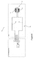
- contact could be made between the conductive portions forming a small circuit between the second and third conductive portions, alternatively this may be a capacitive or inductive circuit as shown in Figure 9 .
- the total measured impedance may include a combination of resistance, capacitance or inductance, in combination or as separate measurements.
- Figure 9 demonstrates further methods of creating measureable impedance. It will be clear to the reader that these are only example methods and may be combined or alternative methods may be used.
- a measurement may be of the resistance between a first electrically conductive portion 4 (which in the preferred embodiment is part of the deformable member 3), adjacent to the resilient deformable member 3, in physical contact with a second electrically conductive portion 6 below the member.
- a third electrically conductive portion 7 may be present on the contact sensing member, or elsewhere. This portion may allow a circuit to be formed between the first, second and third contact members for sensing.
- the first conductive portion may be on (part of) the resilient deformable member 3.
- Figures 9c and 9d demonstrate alternative embodiments which may measure capacitive impedance.
- Figure 9c shows a first electrically conductive member 4 and a second electrically conductive member 6 separated by a (or part of a) resilient deformable member 3.
- the member 3 acts as a dielectric between the two conductive portions and movement of the resilient deformable member will result in a change in the level of capacitance of the electrical relationship between the portions.
- a further embodiment is shown where a third electrically conductive portion 7 is present, located on the contact sensing member 6.
- first electrically conductive portion 4 may be adjacent to the resilient deformable member 3 - placed directly above or separated by an air-gap or intermediate layer - or the first electrically conductive portion 4 may be on (part of or encapsulated by) the resilient deformable member 3.
- Figures 9e and 9f demonstrate further alternative embodiments which may measure inductive impedance.
- Figure 9e shows a system in which first 4 and second 6 electrically conductive members may be coils or loops.
- the resilient deformable member 3 may comprise a silicon doped ferrite core to increase the effect of any tamper induced deformation, or may be separate thereto, and simply hold the core proximate the coils. Tamper induced deformation may be measured by the change in inductance between the conductive portions.
- the conductive members may be wound around areas of the tamper detection element as would be known by one skilled in the art.
- Figure 9f shows a further embodiment where both the first 4 and second 6 electrically conductive portions are located on the contact sensing member.
- the resilient deformable member 3 may be doped with ferrite (or support a separate core) so as to provide a magnetically permeable core to improve coupling between the conductive portions.
- circuit traces may also be present in the printed wire board for redundancy or other purposes.
- the tamper detection element 1 also has a housing 9.
- the housing is designed to contain the contact sensing member and the resilient deformable member and ensure appropriate contact and positioning between them. It can also serve to protect the members 3 and 5 to prevent tampering with them.
- the housing is hollowed out in the direction towards the resilient deformable member 3 and contact sensing member 5 to at least receive the head 14 of the contact sensing member 5 and a substantial part of the resilient deformable member 3.
- the housing 9 may also have one or more engaging features 19 to provide engagement and holding with a tool (not shown).
- the engaging features 19 are flat as shown on a side wall and opposing side wall of the housing 9 for holding by pliers or a spanner or similar tool.
- the housing may be substantially larger than the contact sensing member 5.
- the additional space in the housing may contain a printed wire board.
- the printed wire board may comprise further security features and/or may comprise an interface between the contact sensing member 5 and the tail 15.
- the printed wire board may be shaped to fit in a hollow region of the housing.
- the shape of the housing may provide means to easily remove or attach the device.
- the tail 15 may be detachable from the housing, in some cases allowing easier installation.
- the housing may be hollowed out in the direction towards the resilient deformable member 3, allowing contact or close proximity between resilient deformable member 3 and the contact sensing member 5.
- the housing 9 is preferably made from a resilient material. This material may be similar to that used for the second member 8, in the embodiment shown this may be stainless steel or a similar metal. In a preferred embodiment the material may be a resilient plastic, for example the plastic may be PVC. As shown in Figure 2 the housing 9 is an endless member and is contoured to conform with those parts of the contact sensing member 5 and resilient deformable member 3 which reside therein. In a particular embodiment the housing may appear substantially rectangular. The rectangle may have rounded corners to contour to a second member 8 it is attached to. The end of the rectangle distal from the second member 8 may have substantially sharp corners and may comprise the tail 15, or the attachment means for the tail 15.
- FIG. 3a, 3b and 4 An embodiment of the assembly of the tamper detection element 1 is shown in Figures 3a, 3b and 4 .
- a first member 2 to which the tamper detection element 1 is attached.
- the second member is a threaded fastener 8a together with a nut 8b thereon.
- the contact sensing member 5 is assembled with the housing 9 (though typically this will be preassembled and come as a sub assembly) together with the resilient deformable member 3.
- the resiliently deformable member may already be held captive in the housing or maybe assembled with it as required.
- the tamper detection element 1 is then located in the example shown over the threaded fastener 8a and if necessary if not assembled beforehand the resiliently deformable member 3 is then located there over and into the appropriate cavity in the housing 9.
- the securing nut 8b is done up over the thread fastener 8a to lock the assembled tamper detection element 1 in place.
- the resiliently deformable member 3 is squashed between the second member 8 (in this case the threaded fastener 8a and nut 8b) and the contact sensing member 5.
- Shown in Figure 4 also is the first electrically conductive portion 4 of the resilient deformable member 3.
- the first electrically conductive portion 4 is held against the second electrically conductive portion 6 and in the preferred embodiment the third electrically conductive portion 7.
- a voltage or current is applied to the second electrically conductive portion 6 a circuit is formed across to the third electrically conductive portion 7 via the first electrically conductive portion 4.
- an AC current or voltage may be used.
- the degree of pressure of the first electrically conductive portion 4 will vary the impedance between the second and third electrically conductive portions 6 and 7 respectively. This effect, caused by the tamper induced deformation of the resilient deformable member 3 may be enhanced by appropriate selection of the resilient deformable member 3 material.
- a base reading can be taken and thereafter variance in this base reading, for example the total impedance of the circuit, outside of certain thresholds will indicate that tampering is occurring, for example the distance between the first member 2 and second member 8 is changing.
- an unauthorised user may be undoing the nut at 8b which will then reduce the pressure of the resilient deformable member 3 against the contact sensing member 5 thus resulting in an increased impedance of this circuit. Once this exceeds the threshold value then an alarm or tampering event will be triggered.
- the circuit may be formed and measured between the first electrically conductive portion 4 and the second electrically conductive portion 6 only.
- first electrically conductive portion 4 there may not be direct contact between the first electrically conductive portion 4 and the second electrically conductive portion 6.
- a capacitance may be measured and the pressure between the resilient deformable member and the contact sensing member 5 will alter the relationship between the members and the impedance will change.
- the resilient deformable member 3 will "ooze" out the hole that is formed and reduce the pressure of the portion 4 against, or proximate the portion or portions 6 and 7 and therefore again vary the impedance of the circuit.
- the resilient deformable member is adapted to allow this tamper induced deformation.
- the material used for the resilient deformable member may be selected to enhance characteristics of the tamper induced deformation. This is shown in Figure 5 , where part of the housing 9A has been broken away. This again will once a threshold is exceeded result in an alarm or tamper alert.
- the first member 2 is a mounting plate and this for example could be the plate of a piece of equipment through which the second member 8b as a threaded member is passed there through to hold for example a further piece of equipment against the first member 2 and when an attempt is made to remove or alter any of the pieces of equipment by tampering with the tamper detection element 1 an alarm will result.
- any attempt to create relative movement between the first member 2 and second member 8 (or elements 8a or 8b) will result in a reduced or varied impedance of the circuit and again once the threshold is exceeded an alarm will sound.
- the tamper detection element may be connected to a separate measurement device, preferably through a connecting wire or cable.
- the tail 15 is preferably a flat cable and may contain further traces or security devices. In a preferred embodiment this is a flat USB cable.
- Figure 6 shows an embodiment of this connection using a 5 wire cable.
- separate electrical connection is made to each of the electrically conductive portions 6 and 7.
- a single electrical connection may be used, particularly if measuring the impedance or capacitance.
- further electrical connections may be used or further tracks may be present on the tail or measuring device for signal noise reduction or security means.
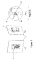
- FIGs 7a, b and Figure 8 Such an assembly is shown in Figures 7a, b and Figure 8 where a piece of equipment 12 in this case a security key pad is held to a plate or first member 2 via a threaded fastener as the second member 8. Any attempt for example to undo the security nut 8b will result in a varied impedance of the circuit and sound an alarm.
- the tail 15 on the contact sensing member 5 can be seen and in this case it is loomed into the internal parts of the piece of equipment 12.
- the tamper detection element 1 may locate between a first member 2 and second member 8 for example as two plates or portions of a cabinet and when relative movement between the two portions occurs pressure is increased or decreased on the tamper detection element and therefore the resulting impedance in the circuit will vary.
- the tamper detection element 1 may be in cased or packaged to retain all parts therein and may have some form of adhesive mounting or similar to mount it to one of the two members 2 or 8 and again a base reading taken when the two members are at the correct relationship with each other.
- the equipment 12 to be protected may be assembled with the tamper detection elements 1 as part of its assembly process or the tamper detection elements 1 may be retrofitted to the equipment 12 either on site or as part of the maintenance of the equipment 12.
- detection element there is a plurality of detection elements and these may be arrayed throughout the equipment 12 being protected.
- the detection element may also be provided as a kit of parts, to provide one or more tamper detection elements, for example to equipment 12 assemblers or maintainers for pre or post fitting thereto.
Landscapes
- Engineering & Computer Science (AREA)
- General Engineering & Computer Science (AREA)
- Physics & Mathematics (AREA)
- General Physics & Mathematics (AREA)
- Mechanical Engineering (AREA)
- Burglar Alarm Systems (AREA)
Claims (14)
- Manipulationsdetektionselement (1), das zumindest teilweise angepasst ist, um durch eine Befestigungsvorrichtung (8) an einem ersten Element gehalten zu werden, um unzulässige Manipulation in Bezug auf die Befestigungsvorrichtung (8) oder eine durch die Befestigungsvorrichtung (8) an dem ersten Element gehaltene Vorrichtung zu detektieren, wobei das Manipulationsdetektionselement (1) Folgendes umfasst oder einschließt:ein elastisches verformbares Element (3), das in der Lage ist, sich aufgrund der Manipulation zu verformen, wobei das elastische verformbare Element zumindest teilweise ein Elastomer oder Gummi umfasst,ein starres Gehäuse (9) zur Anordnung und Aufnahme des elastischen verformbaren Elements (3) in Bezug auf das erste Element,ein Kontaktabfühlelement (5), das in Bezug auf das elastische verformbare Element angeordnet ist und im Wesentlichen in dem starren Gehäuse (9) aufgenommen ist;einen ersten elektrisch leitfähigen Abschnitt (4), der benachbart zu oder auf dem elastischen verformbaren Element (3) angeordnet ist; undeinen zweiten elektrisch leitfähigen Abschnitt (6) auf dem Kontaktabfühlelement (5);wobei eine elektrische Kopplung zwischen dem ersten (4) und dem zweiten (6) elektrisch leitfähigen Abschnitt hergestellt werden kann, und eine durch Manipulation induzierte Verformung des elastischen verformbaren Elements (3) eine Variation der Impedanz der elektrischen Kopplung bewirkt, wobei die Variation die Manipulation anzeigt, um ein Lösen der Befestigungsvorrichtung (8) zu detektieren,und wobei das starre Gehäuse (9) ein Endloselement ist und so konturiert ist, um jenen Teilen des Kontaktabfühlelements und des elastischen verformbaren Elements, die in diesem vorliegen, zu entsprechen, so dass eine Manipulation des starren Gehäuses (9) ebenfalls in einer durch Manipulation induzierten Verformung des elastischen verformbaren Elements resultiert, um die Impedanz der elektrischen Kopplung zu variieren, wodurch die Manipulation angezeigt wird.
- Element nach Anspruch 1, wobei das elastische verformbare Element (3) in Verwendung in komprimiertem Zustand gehalten wird.
- Element nach Anspruch 1 oder 2, wobei der zweite elektrisch leitfähige Abschnitt (6) in Bezug auf den ersten elektrisch leitfähigen Abschnitt (4) angeordnet ist.
- Element nach einem der Ansprüche 1 bis 3, wobei ein dritter elektrisch leitfähiger Abschnitt (7) auf dem Kontaktabfühlelement (5) vorliegt und die Impedanz zwischen dem zweiten (6) und dem dritten (7) elektrisch leitfähigen Abschnitt gemessen wird.
- Element nach Anspruch 4, wobei sich die Impedanz aufgrund von Veränderungen in Bezug auf einen Kontaktbereich oder einen Druck oder beides zwischen dem ersten elektrisch leitfähigen Abschnitt (4) und dem zweiten (6) oder dem dritten (7) elektrisch leitfähigen Abschnitt oder beiden verändert.
- Element nach einem der Ansprüche 1 bis 5, wobei das Element (1) zwischen dem ersten Element und einem zweiten Element angeordnet ist, um Manipulation als Relativbewegung zwischen diesen zu detektieren.
- Element nach Anspruch 6, das auch angepasst ist, um durch das zweite Element, das sich mit dem ersten Element in Eingriff befindet, gegenüber dem zweiten Element an Ort und Stelle gehalten zu werden.
- Element nach einem der Ansprüche 1 bis 7, wobei Manipulation in Bezug auf das starre Gehäuse (9) ebenfalls in der Verformung resultiert.
- Verfahren zur Detektion unzulässiger Manipulation in Bezug auf eine Befestigungsvorrichtung (8) oder eine durch die Befestigungsvorrichtung (8) an einem ersten Element gehaltenen Vorrichtung, wobei das Verfahren folgende Schritte umfasst oder einschließt:das Bereitstellen eines elastischen verformbaren Elements (3), das in der Lage ist, sich aufgrund der Manipulation zu verformen, wobei das elastische verformbare Element zumindest teilweise ein Elastomer oder Gummi umfasst;das Bereitstellen eines Kontaktabfühlelements (5), das im Wesentlichen in dem starren Gehäuse (9) aufgenommen ist und in Bezug auf das elastische verformbare Element (3) angeordnet ist;das Bereitstellen eines ersten elektrisch leitfähigen Abschnitts (4) benachbart zu oder auf dem elastischen verformbaren Element (3);das Bereitstellen eines zweiten elektrisch leitfähigen Abschnitts (6) auf dem Kontaktabfühlelement (5);das Bereitstellen eines starren Gehäuses (9), um das elastische verformbare Element (3) und das Kontaktabfühlelement (5) anzuordnen und im Wesentlichen aufzunehmen, wobei das starre Gehäuse ein Endloselement ist und konturiert ist, um jenen Teilen des Kontaktabfühlelements und des elastischen verformbaren Elements zu entsprechen, die in diesem aufgenommen sind;das Verbinden des elastischen verformbaren Elements (3) und/oder des Kontaktabfühlelements (5) oder von beidem mit dem ersten Element durch die Befestigungsvorrichtung (8);das Herstellen einer elektrischen Kopplung zwischen dem ersten (4) und dem zweiten (6) elektrisch leitfähigen Abschnitt;wobei eine durch Manipulation induzierte Verformung des elastischen verformbaren Elements (3) in einer Variation der Impedanz der elektrischen Kopplung resultiert, wodurch die Manipulation angezeigt wird, um das Lösen der Befestigungsvorrichtung (8) zu detektieren;das Messen der Variation unddas Entscheiden, ob ein Manipulationsereignis stattgefunden hat oder nicht.
- Verfahren nach Anspruch 9, wobei das elastische verformbare Element (3) bei Verwendung durch die Befestigungsvorrichtung in komprimiertem Zustand gehalten wird.
- Verfahren nach Anspruch 9 oder 10, wobei die Entscheidung, ob ein Manipulationsereignis stattgefunden hat, den Schritt des Bestimmens, ob die Veränderung einem Schwellenwert entspricht oder diesen überschreitet, umfasst.
- Verfahren nach einem der Ansprüche 9 bis 11, wobei das Verfahren den Schritt des Messens einer Basisablesung der Impedanz umfasst.
- Verfahren nach Anspruch 12, wobei das Verfahren das periodische Messen der Basisablesung der Impedanz umfasst.
- Verfahren nach einem der Ansprüche 9 bis 13, wobei das Verfahren das Auslösen einer Warnung umfasst, wenn ein Manipulationsereignis detektiert wird.
Applications Claiming Priority (2)
| Application Number | Priority Date | Filing Date | Title |
|---|---|---|---|
| NZ60183612 | 2012-08-15 | ||
| PCT/NZ2013/000176 WO2014027905A1 (en) | 2012-08-15 | 2013-09-23 | Improvements in, or relating to, tamper evident systems |
Publications (3)
| Publication Number | Publication Date |
|---|---|
| EP2885774A1 EP2885774A1 (de) | 2015-06-24 |
| EP2885774A4 EP2885774A4 (de) | 2016-04-27 |
| EP2885774B1 true EP2885774B1 (de) | 2019-08-21 |
Family
ID=50685657
Family Applications (1)
| Application Number | Title | Priority Date | Filing Date |
|---|---|---|---|
| EP13869853.5A Not-in-force EP2885774B1 (de) | 2012-08-15 | 2013-09-23 | Verbesserungen an oder im zusammenhang mit gesicherten systemen |
Country Status (4)
| Country | Link |
|---|---|
| US (1) | US9646472B2 (de) |
| EP (1) | EP2885774B1 (de) |
| AU (1) | AU2013303308C1 (de) |
| WO (1) | WO2014027905A1 (de) |
Families Citing this family (10)
| Publication number | Priority date | Publication date | Assignee | Title |
|---|---|---|---|---|
| US9911012B2 (en) | 2015-09-25 | 2018-03-06 | International Business Machines Corporation | Overlapping, discrete tamper-respondent sensors |
| EP3249634B1 (de) * | 2016-05-26 | 2024-05-15 | Nxp B.V. | Manipulationsdetektionsvorrichtung |
| US10299372B2 (en) | 2016-09-26 | 2019-05-21 | International Business Machines Corporation | Vented tamper-respondent assemblies |
| US10327329B2 (en) * | 2017-02-13 | 2019-06-18 | International Business Machines Corporation | Tamper-respondent assembly with flexible tamper-detect sensor(s) overlying in-situ-formed tamper-detect sensor |
| US10875503B2 (en) * | 2018-01-06 | 2020-12-29 | Toyota Motor Engineering & Manufacturing North America, Inc. | System and method for anti-theft control for autonomous vehicle |
| US10306753B1 (en) | 2018-02-22 | 2019-05-28 | International Business Machines Corporation | Enclosure-to-board interface with tamper-detect circuit(s) |
| US11665817B2 (en) | 2019-09-30 | 2023-05-30 | Block, Inc. | Tamper detection based on flexible member connecting circuitry elements |
| US10810570B1 (en) | 2019-09-30 | 2020-10-20 | Square, Inc. | Point of sale device with cradle for mobile computing device |
| US11663368B2 (en) * | 2019-09-30 | 2023-05-30 | Block, Inc. | Tamper detection based on removal of fastener from recess |
| EP3840551A1 (de) * | 2019-12-20 | 2021-06-23 | ZKW Group GmbH | Wagenmodul |
Citations (1)
| Publication number | Priority date | Publication date | Assignee | Title |
|---|---|---|---|---|
| WO2006092591A1 (en) * | 2005-03-01 | 2006-09-08 | Keymat Technology Limited | Anti-tampe devices |
Family Cites Families (38)
| Publication number | Priority date | Publication date | Assignee | Title |
|---|---|---|---|---|
| US3803577A (en) | 1971-04-06 | 1974-04-09 | W Peterson | Connection detection connector |
| US4329681A (en) | 1980-09-18 | 1982-05-11 | Parsons Zane W | Tamper sensor system |
| DE3110581A1 (de) | 1981-03-18 | 1982-12-30 | Hubert 8121 Haunshofen Hammerl | Schalteranordnung fuer eine elektrische alarmeinrichtung |
| EP0195102B1 (de) | 1985-03-20 | 1989-06-28 | Winfred Klink | Elektrischer Kontaktgeber zur Überwachung einer in einem Gewinde oder nachgiebigem Material eingeschraubten Schraube |
| FR2681134B1 (fr) | 1991-09-05 | 1994-09-09 | Sagem | Dispositif pour la detection de l'ouverture d'un appareil. |
| GB9225654D0 (en) * | 1992-12-08 | 1993-01-27 | Lussey David | Tamper detection sensor |
| US5488206A (en) * | 1994-01-31 | 1996-01-30 | Wu; Donald | Joystick switch assembly |
| US5621387A (en) | 1995-08-08 | 1997-04-15 | Elk Products, Inc. | Box |
| JPH09159558A (ja) | 1995-12-05 | 1997-06-20 | Hitachi Ltd | 締結体 |
| US5705981A (en) * | 1996-03-15 | 1998-01-06 | Breed Automotive Technology, Inc. | Secure enclosure with continuous monitoring |
| US6087939A (en) | 1998-09-22 | 2000-07-11 | Se-Kure Controls, Inc. | Security system |
| US6054922A (en) * | 1999-01-13 | 2000-04-25 | International Business Machines Corporation | Enhanced movement detection arrangement |
| US6774807B1 (en) | 1999-03-02 | 2004-08-10 | Cadence Design Systems, Inc. | Tamper detection mechanism |
| US6265973B1 (en) | 1999-04-16 | 2001-07-24 | Transguard Industries, Inc. | Electronic security seal |
| WO2001059544A2 (en) | 2000-02-14 | 2001-08-16 | Rainbow Technologies B.V., Netherlands | Security module system, apparatus and process |
| WO2001063994A2 (en) | 2000-02-23 | 2001-08-30 | Iridian Technologies, Inc. | Tamper proof case for electronic devices having memories with sensitive information |
| GB0012478D0 (en) * | 2000-05-24 | 2000-07-12 | Ibm | Intrusion detection mechanism for cryptographic cards |
| US7066039B1 (en) | 2000-06-16 | 2006-06-27 | Siemens Atkiengesellschaft | Method and device for checking the mechanical fastening of a component to a base body |
| WO2002013159A1 (en) | 2000-08-03 | 2002-02-14 | Jacob Hazan | Bolt tamper sensor |
| US20030066739A1 (en) | 2001-07-02 | 2003-04-10 | Rickenbach Roger D. | Controller with tactile feedback |
| US7042354B2 (en) | 2002-12-11 | 2006-05-09 | Hi-G-Tek Ltd. | Tamper-resistant electronic seal |
| US6956479B2 (en) | 2003-02-05 | 2005-10-18 | Vanguard Products Group, Inc. | Sensors and methods for detecting attachment to a surface |
| US7113103B2 (en) | 2003-09-11 | 2006-09-26 | General Electric Company | Modular security, monitoring, and control devices and methods |
| US7049970B2 (en) | 2003-10-22 | 2006-05-23 | International Business Machines Corporation | Tamper sensing method and apparatus |
| US7373846B2 (en) | 2004-09-07 | 2008-05-20 | Honda Motor Co., Ltd. | Load cell attachment structure |
| US20070080802A1 (en) | 2005-08-22 | 2007-04-12 | Cockburn John M | Tamper & intrusion detection device |
| US7259341B2 (en) | 2005-09-22 | 2007-08-21 | Ingenico Canada Ltd. | Tamper switch actuator arrangement |
| US7317401B2 (en) | 2005-10-07 | 2008-01-08 | International Business Machines Corporation | Method and mechanical tamper-evident case fastener |
| US7528717B2 (en) | 2006-06-14 | 2009-05-05 | Honeywell International Inc. | Tamper detection mechanism for blind installation of circular sensors |
| US7768397B1 (en) | 2006-09-01 | 2010-08-03 | Vanguard Products Group, Inc. | Cable assembly for securing hinged products |
| DE102007020882B4 (de) | 2007-05-04 | 2014-02-13 | Knorr-Bremse Systeme für Nutzfahrzeuge GmbH | Einrichtung zur Überprüfung der Befestigung einer Leiterbahnplatte an einem Träger |
| US20090091144A1 (en) | 2007-10-05 | 2009-04-09 | Robert Debrody | Bolt Security Seal with Reusable Electronics Module and Bolt |
| US7671276B2 (en) | 2007-11-28 | 2010-03-02 | Baker David L | Armed junction box enclosure |
| DE102007057477B4 (de) | 2007-11-29 | 2010-01-28 | Hypercom Gmbh | Vorrichtung zum Überwachen eines Raumes durch seriell verschaltete Schließkontakte, insbesondere Deckelschalter in einem Sicherungsgehäuse |
| CN101319691B (zh) | 2008-06-10 | 2010-04-14 | 盛月忠 | 电子防盗螺母 |
| EP2239651B1 (de) | 2009-03-27 | 2017-08-30 | CSEM Centre Suisse d'Electronique et de Microtechnique SA - Recherche et Développement | Intelligentes Etikett |
| US8278948B2 (en) * | 2009-08-10 | 2012-10-02 | Apple Inc. | Mechanisms for detecting tampering of an electronic device |
| US8358218B2 (en) | 2010-03-02 | 2013-01-22 | Verifone, Inc. | Point of sale terminal having enhanced security |
-
2013
- 2013-09-23 EP EP13869853.5A patent/EP2885774B1/de not_active Not-in-force
- 2013-09-23 AU AU2013303308A patent/AU2013303308C1/en not_active Ceased
- 2013-09-23 WO PCT/NZ2013/000176 patent/WO2014027905A1/en active Application Filing
- 2013-09-23 US US14/421,295 patent/US9646472B2/en active Active
Patent Citations (1)
| Publication number | Priority date | Publication date | Assignee | Title |
|---|---|---|---|---|
| WO2006092591A1 (en) * | 2005-03-01 | 2006-09-08 | Keymat Technology Limited | Anti-tampe devices |
Also Published As
| Publication number | Publication date |
|---|---|
| US9646472B2 (en) | 2017-05-09 |
| EP2885774A1 (de) | 2015-06-24 |
| AU2013303308B2 (en) | 2017-10-12 |
| WO2014027905A1 (en) | 2014-02-20 |
| EP2885774A4 (de) | 2016-04-27 |
| AU2013303308C1 (en) | 2018-01-18 |
| AU2013303308A1 (en) | 2015-03-05 |
| US20150199887A1 (en) | 2015-07-16 |
Similar Documents
| Publication | Publication Date | Title |
|---|---|---|
| EP2885774B1 (de) | Verbesserungen an oder im zusammenhang mit gesicherten systemen | |
| US7843339B2 (en) | Secure point of sale device employing capacitive sensors | |
| EP1964082B1 (de) | Programmierbares alarmmodul und -system zum schutz von merchandise-artikeln | |
| CA2879857C (en) | Integrated antenna coil in a metallic body | |
| US9213869B2 (en) | Magnetic stripe reading device | |
| US8167204B2 (en) | Wireless damage location sensing system | |
| US9171439B2 (en) | Method and apparatus for powering a security device | |
| US20100328113A1 (en) | Keypad membrane security | |
| US9269241B2 (en) | Tamper-resistant security device | |
| JPH02504561A (ja) | 窃盗防止タッグおよびその使用方法 | |
| US9831050B2 (en) | Tamper resistant rugged keypad | |
| CN112525277B (zh) | 具有防盗气功能的燃气表、防盗气方法及燃气管理系统 | |
| US4069405A (en) | Swimming pool alarm system | |
| US7790993B2 (en) | Anti-intrusion device primarily for an electronic payment terminal | |
| US10013582B2 (en) | Secure data entry device | |
| NZ615339B2 (en) | Improvements in, or relating to, tamper evident systems | |
| US8847580B1 (en) | Tamperproof magnetic proximity sensor | |
| EP3286742B1 (de) | Kassenendgerät mit erhöhter sicherheit | |
| US8985467B2 (en) | Permanently deactivatable security tag | |
| AU777178B2 (en) | Securing element for electronically securing articles | |
| WO2016086968A1 (en) | Secure pos housing | |
| RU2529861C1 (ru) | Система датчиков контроля размещения оборудования в телекоммуникационной стойке | |
| WO2008078108A2 (en) | Magnetic field indicator and utility meter incorporating the same | |
| CN215804314U (zh) | 一种用于三辊闸机的防逃票阻挡装置 | |
| KR200216979Y1 (ko) | 상품도난방지장치 |
Legal Events
| Date | Code | Title | Description |
|---|---|---|---|
| PUAI | Public reference made under article 153(3) epc to a published international application that has entered the european phase |
Free format text: ORIGINAL CODE: 0009012 |
|
| 17P | Request for examination filed |
Effective date: 20150310 |
|
| AK | Designated contracting states |
Kind code of ref document: A1 Designated state(s): AL AT BE BG CH CY CZ DE DK EE ES FI FR GB GR HR HU IE IS IT LI LT LU LV MC MK MT NL NO PL PT RO RS SE SI SK SM TR |
|
| AX | Request for extension of the european patent |
Extension state: BA ME |
|
| DAX | Request for extension of the european patent (deleted) | ||
| RAP1 | Party data changed (applicant data changed or rights of an application transferred) |
Owner name: PAYMENT EXPRESS LIMITED |
|
| RA4 | Supplementary search report drawn up and despatched (corrected) |
Effective date: 20160329 |
|
| RIC1 | Information provided on ipc code assigned before grant |
Ipc: G08B 13/08 20060101ALI20160321BHEP Ipc: G08B 13/06 20060101AFI20160321BHEP Ipc: F16B 41/00 20060101ALI20160321BHEP |
|
| GRAP | Despatch of communication of intention to grant a patent |
Free format text: ORIGINAL CODE: EPIDOSNIGR1 |
|
| STAA | Information on the status of an ep patent application or granted ep patent |
Free format text: STATUS: GRANT OF PATENT IS INTENDED |
|
| INTG | Intention to grant announced |
Effective date: 20170110 |
|
| GRAJ | Information related to disapproval of communication of intention to grant by the applicant or resumption of examination proceedings by the epo deleted |
Free format text: ORIGINAL CODE: EPIDOSDIGR1 |
|
| STAA | Information on the status of an ep patent application or granted ep patent |
Free format text: STATUS: REQUEST FOR EXAMINATION WAS MADE |
|
| INTC | Intention to grant announced (deleted) | ||
| STAA | Information on the status of an ep patent application or granted ep patent |
Free format text: STATUS: EXAMINATION IS IN PROGRESS |
|
| 17Q | First examination report despatched |
Effective date: 20170616 |
|
| GRAP | Despatch of communication of intention to grant a patent |
Free format text: ORIGINAL CODE: EPIDOSNIGR1 |
|
| STAA | Information on the status of an ep patent application or granted ep patent |
Free format text: STATUS: GRANT OF PATENT IS INTENDED |
|
| INTG | Intention to grant announced |
Effective date: 20190307 |
|
| GRAS | Grant fee paid |
Free format text: ORIGINAL CODE: EPIDOSNIGR3 |
|
| GRAA | (expected) grant |
Free format text: ORIGINAL CODE: 0009210 |
|
| STAA | Information on the status of an ep patent application or granted ep patent |
Free format text: STATUS: THE PATENT HAS BEEN GRANTED |
|
| AK | Designated contracting states |
Kind code of ref document: B1 Designated state(s): AL AT BE BG CH CY CZ DE DK EE ES FI FR GB GR HR HU IE IS IT LI LT LU LV MC MK MT NL NO PL PT RO RS SE SI SK SM TR |
|
| RAP1 | Party data changed (applicant data changed or rights of an application transferred) |
Owner name: WINDCAVE LIMITED |
|
| REG | Reference to a national code |
Ref country code: GB Ref legal event code: FG4D |
|
| REG | Reference to a national code |
Ref country code: CH Ref legal event code: EP |
|
| REG | Reference to a national code |
Ref country code: DE Ref legal event code: R096 Ref document number: 602013059588 Country of ref document: DE |
|
| REG | Reference to a national code |
Ref country code: AT Ref legal event code: REF Ref document number: 1170631 Country of ref document: AT Kind code of ref document: T Effective date: 20190915 |
|
| REG | Reference to a national code |
Ref country code: IE Ref legal event code: FG4D |
|
| REG | Reference to a national code |
Ref country code: LT Ref legal event code: MG4D |
|
| REG | Reference to a national code |
Ref country code: NL Ref legal event code: MP Effective date: 20190821 |
|
| PG25 | Lapsed in a contracting state [announced via postgrant information from national office to epo] |
Ref country code: FI Free format text: LAPSE BECAUSE OF FAILURE TO SUBMIT A TRANSLATION OF THE DESCRIPTION OR TO PAY THE FEE WITHIN THE PRESCRIBED TIME-LIMIT Effective date: 20190821 Ref country code: LT Free format text: LAPSE BECAUSE OF FAILURE TO SUBMIT A TRANSLATION OF THE DESCRIPTION OR TO PAY THE FEE WITHIN THE PRESCRIBED TIME-LIMIT Effective date: 20190821 Ref country code: HR Free format text: LAPSE BECAUSE OF FAILURE TO SUBMIT A TRANSLATION OF THE DESCRIPTION OR TO PAY THE FEE WITHIN THE PRESCRIBED TIME-LIMIT Effective date: 20190821 Ref country code: PT Free format text: LAPSE BECAUSE OF FAILURE TO SUBMIT A TRANSLATION OF THE DESCRIPTION OR TO PAY THE FEE WITHIN THE PRESCRIBED TIME-LIMIT Effective date: 20191223 Ref country code: NL Free format text: LAPSE BECAUSE OF FAILURE TO SUBMIT A TRANSLATION OF THE DESCRIPTION OR TO PAY THE FEE WITHIN THE PRESCRIBED TIME-LIMIT Effective date: 20190821 Ref country code: SE Free format text: LAPSE BECAUSE OF FAILURE TO SUBMIT A TRANSLATION OF THE DESCRIPTION OR TO PAY THE FEE WITHIN THE PRESCRIBED TIME-LIMIT Effective date: 20190821 Ref country code: BG Free format text: LAPSE BECAUSE OF FAILURE TO SUBMIT A TRANSLATION OF THE DESCRIPTION OR TO PAY THE FEE WITHIN THE PRESCRIBED TIME-LIMIT Effective date: 20191121 Ref country code: NO Free format text: LAPSE BECAUSE OF FAILURE TO SUBMIT A TRANSLATION OF THE DESCRIPTION OR TO PAY THE FEE WITHIN THE PRESCRIBED TIME-LIMIT Effective date: 20191121 |
|
| PG25 | Lapsed in a contracting state [announced via postgrant information from national office to epo] |
Ref country code: GR Free format text: LAPSE BECAUSE OF FAILURE TO SUBMIT A TRANSLATION OF THE DESCRIPTION OR TO PAY THE FEE WITHIN THE PRESCRIBED TIME-LIMIT Effective date: 20191122 Ref country code: LV Free format text: LAPSE BECAUSE OF FAILURE TO SUBMIT A TRANSLATION OF THE DESCRIPTION OR TO PAY THE FEE WITHIN THE PRESCRIBED TIME-LIMIT Effective date: 20190821 Ref country code: IS Free format text: LAPSE BECAUSE OF FAILURE TO SUBMIT A TRANSLATION OF THE DESCRIPTION OR TO PAY THE FEE WITHIN THE PRESCRIBED TIME-LIMIT Effective date: 20191221 Ref country code: RS Free format text: LAPSE BECAUSE OF FAILURE TO SUBMIT A TRANSLATION OF THE DESCRIPTION OR TO PAY THE FEE WITHIN THE PRESCRIBED TIME-LIMIT Effective date: 20190821 Ref country code: AL Free format text: LAPSE BECAUSE OF FAILURE TO SUBMIT A TRANSLATION OF THE DESCRIPTION OR TO PAY THE FEE WITHIN THE PRESCRIBED TIME-LIMIT Effective date: 20190821 |
|
| REG | Reference to a national code |
Ref country code: AT Ref legal event code: MK05 Ref document number: 1170631 Country of ref document: AT Kind code of ref document: T Effective date: 20190821 |
|
| PG25 | Lapsed in a contracting state [announced via postgrant information from national office to epo] |
Ref country code: TR Free format text: LAPSE BECAUSE OF FAILURE TO SUBMIT A TRANSLATION OF THE DESCRIPTION OR TO PAY THE FEE WITHIN THE PRESCRIBED TIME-LIMIT Effective date: 20190821 |
|
| REG | Reference to a national code |
Ref country code: DE Ref legal event code: R119 Ref document number: 602013059588 Country of ref document: DE |
|
| PG25 | Lapsed in a contracting state [announced via postgrant information from national office to epo] |
Ref country code: PL Free format text: LAPSE BECAUSE OF FAILURE TO SUBMIT A TRANSLATION OF THE DESCRIPTION OR TO PAY THE FEE WITHIN THE PRESCRIBED TIME-LIMIT Effective date: 20190821 Ref country code: DK Free format text: LAPSE BECAUSE OF FAILURE TO SUBMIT A TRANSLATION OF THE DESCRIPTION OR TO PAY THE FEE WITHIN THE PRESCRIBED TIME-LIMIT Effective date: 20190821 Ref country code: RO Free format text: LAPSE BECAUSE OF FAILURE TO SUBMIT A TRANSLATION OF THE DESCRIPTION OR TO PAY THE FEE WITHIN THE PRESCRIBED TIME-LIMIT Effective date: 20190821 Ref country code: IT Free format text: LAPSE BECAUSE OF FAILURE TO SUBMIT A TRANSLATION OF THE DESCRIPTION OR TO PAY THE FEE WITHIN THE PRESCRIBED TIME-LIMIT Effective date: 20190821 Ref country code: AT Free format text: LAPSE BECAUSE OF FAILURE TO SUBMIT A TRANSLATION OF THE DESCRIPTION OR TO PAY THE FEE WITHIN THE PRESCRIBED TIME-LIMIT Effective date: 20190821 Ref country code: EE Free format text: LAPSE BECAUSE OF FAILURE TO SUBMIT A TRANSLATION OF THE DESCRIPTION OR TO PAY THE FEE WITHIN THE PRESCRIBED TIME-LIMIT Effective date: 20190821 |
|
| PG25 | Lapsed in a contracting state [announced via postgrant information from national office to epo] |
Ref country code: SK Free format text: LAPSE BECAUSE OF FAILURE TO SUBMIT A TRANSLATION OF THE DESCRIPTION OR TO PAY THE FEE WITHIN THE PRESCRIBED TIME-LIMIT Effective date: 20190821 Ref country code: SM Free format text: LAPSE BECAUSE OF FAILURE TO SUBMIT A TRANSLATION OF THE DESCRIPTION OR TO PAY THE FEE WITHIN THE PRESCRIBED TIME-LIMIT Effective date: 20190821 Ref country code: MC Free format text: LAPSE BECAUSE OF FAILURE TO SUBMIT A TRANSLATION OF THE DESCRIPTION OR TO PAY THE FEE WITHIN THE PRESCRIBED TIME-LIMIT Effective date: 20190821 Ref country code: IS Free format text: LAPSE BECAUSE OF FAILURE TO SUBMIT A TRANSLATION OF THE DESCRIPTION OR TO PAY THE FEE WITHIN THE PRESCRIBED TIME-LIMIT Effective date: 20200224 Ref country code: CZ Free format text: LAPSE BECAUSE OF FAILURE TO SUBMIT A TRANSLATION OF THE DESCRIPTION OR TO PAY THE FEE WITHIN THE PRESCRIBED TIME-LIMIT Effective date: 20190821 |
|
| REG | Reference to a national code |
Ref country code: CH Ref legal event code: PL |
|
| PLBE | No opposition filed within time limit |
Free format text: ORIGINAL CODE: 0009261 |
|
| STAA | Information on the status of an ep patent application or granted ep patent |
Free format text: STATUS: NO OPPOSITION FILED WITHIN TIME LIMIT |
|
| PG2D | Information on lapse in contracting state deleted |
Ref country code: IS |
|
| PG25 | Lapsed in a contracting state [announced via postgrant information from national office to epo] |
Ref country code: DE Free format text: LAPSE BECAUSE OF NON-PAYMENT OF DUE FEES Effective date: 20200401 Ref country code: LU Free format text: LAPSE BECAUSE OF NON-PAYMENT OF DUE FEES Effective date: 20190923 Ref country code: CH Free format text: LAPSE BECAUSE OF NON-PAYMENT OF DUE FEES Effective date: 20190930 Ref country code: LI Free format text: LAPSE BECAUSE OF NON-PAYMENT OF DUE FEES Effective date: 20190930 Ref country code: IE Free format text: LAPSE BECAUSE OF NON-PAYMENT OF DUE FEES Effective date: 20190923 |
|
| 26N | No opposition filed |
Effective date: 20200603 |
|
| REG | Reference to a national code |
Ref country code: BE Ref legal event code: MM Effective date: 20190930 |
|
| PG25 | Lapsed in a contracting state [announced via postgrant information from national office to epo] |
Ref country code: SI Free format text: LAPSE BECAUSE OF FAILURE TO SUBMIT A TRANSLATION OF THE DESCRIPTION OR TO PAY THE FEE WITHIN THE PRESCRIBED TIME-LIMIT Effective date: 20190821 Ref country code: BE Free format text: LAPSE BECAUSE OF NON-PAYMENT OF DUE FEES Effective date: 20190930 |
|
| PG25 | Lapsed in a contracting state [announced via postgrant information from national office to epo] |
Ref country code: ES Free format text: LAPSE BECAUSE OF FAILURE TO SUBMIT A TRANSLATION OF THE DESCRIPTION OR TO PAY THE FEE WITHIN THE PRESCRIBED TIME-LIMIT Effective date: 20190821 Ref country code: FR Free format text: LAPSE BECAUSE OF NON-PAYMENT OF DUE FEES Effective date: 20191021 |
|
| PG25 | Lapsed in a contracting state [announced via postgrant information from national office to epo] |
Ref country code: CY Free format text: LAPSE BECAUSE OF FAILURE TO SUBMIT A TRANSLATION OF THE DESCRIPTION OR TO PAY THE FEE WITHIN THE PRESCRIBED TIME-LIMIT Effective date: 20190821 |
|
| PG25 | Lapsed in a contracting state [announced via postgrant information from national office to epo] |
Ref country code: MT Free format text: LAPSE BECAUSE OF FAILURE TO SUBMIT A TRANSLATION OF THE DESCRIPTION OR TO PAY THE FEE WITHIN THE PRESCRIBED TIME-LIMIT Effective date: 20190821 Ref country code: HU Free format text: LAPSE BECAUSE OF FAILURE TO SUBMIT A TRANSLATION OF THE DESCRIPTION OR TO PAY THE FEE WITHIN THE PRESCRIBED TIME-LIMIT; INVALID AB INITIO Effective date: 20130923 |
|
| PG25 | Lapsed in a contracting state [announced via postgrant information from national office to epo] |
Ref country code: MK Free format text: LAPSE BECAUSE OF FAILURE TO SUBMIT A TRANSLATION OF THE DESCRIPTION OR TO PAY THE FEE WITHIN THE PRESCRIBED TIME-LIMIT Effective date: 20190821 |
|
| PGFP | Annual fee paid to national office [announced via postgrant information from national office to epo] |
Ref country code: GB Payment date: 20220802 Year of fee payment: 10 |
|
| GBPC | Gb: european patent ceased through non-payment of renewal fee |
Effective date: 20230923 |