EP2885633B1 - Verfahren zur Messung der Ionenkonzentration eines Analyten mit einem mikromechanischen Chip eines ionenselektiven Sensors - Google Patents
Verfahren zur Messung der Ionenkonzentration eines Analyten mit einem mikromechanischen Chip eines ionenselektiven Sensors Download PDFInfo
- Publication number
- EP2885633B1 EP2885633B1 EP13753129.9A EP13753129A EP2885633B1 EP 2885633 B1 EP2885633 B1 EP 2885633B1 EP 13753129 A EP13753129 A EP 13753129A EP 2885633 B1 EP2885633 B1 EP 2885633B1
- Authority
- EP
- European Patent Office
- Prior art keywords
- micro channel
- analyte
- solution
- liquid membrane
- electrolyte
- Prior art date
- Legal status (The legal status is an assumption and is not a legal conclusion. Google has not performed a legal analysis and makes no representation as to the accuracy of the status listed.)
- Active
Links
Images





Classifications
-
- G—PHYSICS
- G01—MEASURING; TESTING
- G01N—INVESTIGATING OR ANALYSING MATERIALS BY DETERMINING THEIR CHEMICAL OR PHYSICAL PROPERTIES
- G01N27/00—Investigating or analysing materials by the use of electric, electrochemical, or magnetic means
- G01N27/26—Investigating or analysing materials by the use of electric, electrochemical, or magnetic means by investigating electrochemical variables; by using electrolysis or electrophoresis
- G01N27/28—Electrolytic cell components
- G01N27/30—Electrodes, e.g. test electrodes; Half-cells
- G01N27/333—Ion-selective electrodes or membranes
-
- B—PERFORMING OPERATIONS; TRANSPORTING
- B01—PHYSICAL OR CHEMICAL PROCESSES OR APPARATUS IN GENERAL
- B01L—CHEMICAL OR PHYSICAL LABORATORY APPARATUS FOR GENERAL USE
- B01L3/00—Containers or dishes for laboratory use, e.g. laboratory glassware; Droppers
- B01L3/50—Containers for the purpose of retaining a material to be analysed, e.g. test tubes
- B01L3/502—Containers for the purpose of retaining a material to be analysed, e.g. test tubes with fluid transport, e.g. in multi-compartment structures
- B01L3/5027—Containers for the purpose of retaining a material to be analysed, e.g. test tubes with fluid transport, e.g. in multi-compartment structures by integrated microfluidic structures, i.e. dimensions of channels and chambers are such that surface tension forces are important, e.g. lab-on-a-chip
Definitions
- the present invention relates to a method of measuring ion concentration of an analyte solution by using a micro machined chip for a low-cost disposable ion-selective sensor.
- Potentiometric ion-selective sensors are extremely easy, label-free methods of measurement.
- the measurement of a potentiometric ion-selective sensor is based on the equilibrium of ions between the different phases of the sensor and at the sensor/analyte interface. This means that the different phases are potentially affected by the measurement, due to exchange of chemical species. These changes lead to a drift in the signal, and eventually to a degradation of the signal. This causes the need for frequent recalibration as well as a degradation of the sensor.
- Ion sensing is a routine technology in many analytical laboratories, which is used for timepoint measurements.
- miniaturized ion-selective electrodes have a limited lifetime, due to the degradation of the materials and/or of the interfaces geometry, which can partly be due to stagnating liquids at the level of the ion sensing membrane. This can lead to changes in the interfacial equilibrium of the ions.
- miniaturized ion-selective sensors are at this day available on the market, their use is mainly still limited to single-use sensors.
- the ideal miniaturized sensor is an all-solid-state sensor. This means that the sensor is completely solid.
- the conventional ion-selective electrodes however have a liquid aqueous internal electrolyte. Although more rigid than conventional electrodes, coated wire electrodes and CHEMFETS have the membrane directly coated respectively onto a metal wire and the gate region of a solid-state field effect transistor.
- the miniaturization has been performed by exchanging of the conventional aqueous phase with for example hydrogels, conductive polymers ( Bobacka, Electroanalysis 18, 2006, No. 1, pp. 7-18 ), carbon nanotubes ( G. Crespo, Anal. Chem., 2008, 80(4), pp. 1316-1322 ), but without reaching the stability of a conventional electrode.
- Manz comprises a micro channel for the analyte solution and a micro channel junction structure containing a liquid membrane that separates the analyte from the electrolyte solution.
- the solution proposed by R. Tantra and A. Manz still requires an electrode reservoir and a conventional Ag/AgCl electrode, which may lead to long-term drift problems due to the stagnating electrode volume.
- the proposed solution is not fully integrated in a microchip, so that the proposed method is still semi-standard and thus difficult to industrialize.
- the fact that the solution proposed in A. Manz is not fully integrated in a microchip limits as well the possibility of integration of multiple sensors on a single device.
- microfluidic ion-selective sensor is US 2003/0112013 A1 where an inert, porous supporting material can be stored in a chamber where the ion-selective membrane is contained in.
- This can be a ceramic, which is provided to support the ion-selective membrane to improve the mechanic stability of the membrane.
- the invention intends to solve the limitations of ion-selective sensors of prior art and relates more precisely to a method of measuring ion concentration of an analyte solution by using a micro machined chip for an ion-selective sensor in which three micro channels are micro machined:
- the micro machined chip for the ion-selective sensor comprises further at least two substrates:
- Said analyte micro channel and said liquid membrane micro channel and said electrolyte micro channel are structured so as to provide, at each of their extremities, an opening intended for an inlet and outlet of their respective liquid solution.
- the micro machined chip is further characterised in that the assembly of said first and said second substrates closes said analyte micro channel, said first electrolyte micro channel and said first liquid membrane micro channel, and is further also characterised in that a first reservoir is formed, after said assembly, at the interface between the analyte micro channel and the electrolyte micro channel, said first reservoir being connected to said analyte micro channel, to the first electrolyte micro channel and to the first liquid membrane micro channel and is intended to receive and retain an ion-selective liquid membrane able to separate the analyte and electrolyte liquids drawn in their respective micro channels.
- the realisation of a confluent reservoir, interconnecting micro channels for the analyte solution, the electrolyte solution and the liquid membrane solution allows to achieve a fully integrated ion-sensor on a microchip, leading to a lower cost and also having the property of a long-term stability, which are two of the limitations of the devices taught in prior art.
- the ion-selective sensor has the additional advantage to be stored in a dry environment so that the liquid membrane and the electrolyte solution can be introduced in said sensor just before the ion concentration measurement of the analyte solution.
- the possibility to introduce the liquid membrane immediately before the use of the sensor avoids possible problems coming from the aging of the liquid membrane due to the storage time of the sensor assembly, as well as disruptive phenomena that could be generated by the too long contact between the sensor assembly and the plasticizer-based liquid membrane.
- a porous layer is arranged in said reservoir.
- the porous layer may be, preliminary to the assembly of the first substrate and the second substrate, arranged into one of the mentioned recesses.
- the advantage of using a porous layer is that the porous layer may be soaked with ion-selective liquid membrane solution prior to the assembly of first substrate and second substrate. This results in an improved stability of the liquid membrane and a better reliability of the separation of the analyte solution and the electrolyte solution.
- the liquid membrane micro channel and/or the analyte micro channel and/or the electrolyte micro channel may be realised by two portions, one portion being structured on the first substrate and a second portion on the second substrate.
- the first reservoir can be realised by arranging a first recess only in the first substrate.
- the first reservoir may be realised by arranging a second recess arranged in said second substrate, said recess forming the reservoir after assembly of the first and second substrates.
- the first reservoir may also be realised by the alignment, and subsequent assembly of the two substrates comprising a first recess arranged in said first substrate and a second recess arranged in said second substrate, said second recess being arranged opposite to said first recess when the substrates are assembled.
- the ion-selective sensor may be devised wherein said first electrolyte micro channel, the first liquid membrane micro channel and the analyte micro channel are connected to the said first reservoir, and arranged with any relative angle between each of said first electrolyte, first liquid membrane and analyte micro channels.
- This design flexibility allows arranging the micro channel configuration to the specific application and use of the ion-selective sensor.
- the substrates of the micro machined chip of of the ion-selective sensor may be made in any structural material, preferably a polymeric material. This allows achieving a low cost for the ion -selective sensor.
- an ion-selective device comprising a first and a second ion-selective sensors.
- a second ion-selective sensor is arranged to the analyte micro channel of the first ion-selective sensor, this second ion-selective sensor comprising a second reservoir, different from the first reservoir and arranged separated from the said first reservoir.
- the liquid membrane micro channel may be connected to each of the two reservoirs or each reservoir may be connected to a different liquid membrane micro channel, each drawing a separate and possibly different ion-selective liquid solution.
- the two electrolyte micro channels of the ion-selective device may be identical or they may be different and they may draw the same or different electrolyte solutions.
- an arrangement not belonging to the invention is also attained by an ion-selective system comprising a plurality of ion-sensors and/or ion-selective devices arranged on a single analyte micro channel, which can be a straight channel, but also a curved channel, and to which the electrolyte and the liquid membrane micro channels of each of said plurality of ion-sensors are arranged to form any angle with the single analyte micro channel.
- the advantage of arranging different ion-sensors and/or ion-selective devices on a single analyte micro channel is that more than two ion species can be detected in a single analyte solution.
- the plurality of ion-sensors may each be arranged with a porous layer arranged in their respective reservoirs, but not all of said plurality of ion sensors does necessarily have a porous layer arranged in their corresponding reservoir.
- a gas is flown in the electrolyte micro channel and the analyte micro channel, this in order to keep in place the liquid membrane when introducing the analyte and electrolyte solution, and to avoid the mixing of the liquid membrane, the analyte solution and the electrolyte solution.
- the method according to the invention of measuring ion concentration of an analyte solution comprises the steps of:
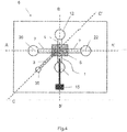
- an ion-selective sensor 6 comprises three microfluidic micro channels, arranged inside the ion-selective sensor 6:
- the ion-selective sensor 6 further comprises:
- the ion-selective sensor 6 comprises, after the assembly of said first substrate 100 and said second substrate 200, a completely formed analyte micro channel 2, a completely formed first electrolyte micro channel 1, and a completely formed first liquid membrane 3 micro channels.
- the ion selective sensor 6 has also a first reservoir 4, arranged at the interface of the first substrate 100 and the second substrate 200 and forming a chamber to which the liquid membrane micro channel 3, the analyte micro channel 2, the electrolyte micro channel 1 are connected and which is intended to receive the ion-selective liquid membrane solution, the analyte solution and the electrolyte solution, by means of their respective micro channels connected to that reservoir 4.
- the electrochemical properties and mechanism of an ion-selective liquid membrane are well known to a person skilled in the art.
- the ion-selective liquid membrane is herein also called the liquid membrane.
- the liquid membrane has an advantageously chosen chemical composition and property for a specific ion-selective electrode, so that the analyte solution and electrolyte solution can be separated by said liquid membrane. Its properties are based on the use of ionophores and lipophilic substances that do not diffuse out of the liquid membrane.
- the ionophore in the liquid membrane allows the analyte ion to solubilize in the liquid membrane and an equilibrium of the analyte ion needs to be achieved at the interface of the analyte and the liquid membrane.
- compositions of liquid membranes can be used and are chosen in function of the analyte solution, the electrolyte solution, the desired surface tension properties of the deployed solutions and also the flow properties of said liquid membrane.
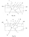
- Fig. 3d illustrates a cross-section of the reservoir 4 of the liquid membrane micro channel 3, the electrolyte micro channel 2 and the analyte micro channel 1, with an ion-selective liquid membrane solution drawn through said reservoir 4.
- This may be achieved, for example, as further described in the method of the invention, by introducing a gas into each of the analyte micro channel and the electrolyte micro channel, or also by using capillary effects.
- the geometry of the reservoir 4 is not drawn to scale and different configurations and geometries of the reservoir 4 may be devised.
- the cross-sections of fig. 3a-d all represent a section according to the line C-C' of fig. 1 .
- Typical widths of the analyte micro channel 2, the electrolyte micro channel 1 are between 10 ⁇ m and 1 mm, preferably 500 ⁇ m.
- Typical widths of the liquid micro channel are between 10 ⁇ m and 500 ⁇ m, preferably 100 ⁇ m.
- Typical lengths of the micro channels are between 1 mm and 20 mm, preferably 15 mm.
- Typical dimensions (i.e. width, length and height) of the reservoir are between 10 ⁇ m x10 ⁇ m x10 ⁇ m and 1000 ⁇ m x1000 ⁇ m x100 ⁇ m, preferably 500 ⁇ m x500 ⁇ m x20 ⁇ m.
- the materials used for the first substrate 100 and the second substrate 200 are preferably chosen among thermoplastic materials. Other materials that can be microstructured by etching or laser techniques may be devised as well. Said substrates may be microstructured with micromechanical techniques, or by chemical etching techniques, or by laser machining techniques, or by hot embossing techniques, or by injection moulding techniques, or by lamination techniques or any combination thereof.
- the first liquid membrane micro channel 3 can be realised by structuring, before assembly of said first substrate 100 and said second substrate 200, a first portion 3a of the first liquid membrane micro channel 3 on said first substrate 100 and a second portion 3b of the first liquid membrane micro channel 3 on said second substrate 200, said first liquid membrane micro channel 3 being formed completely after the alignment and assembly of the first substrate 100 and the second substrate 200.
- the liquid membrane micro channel 3 may present only an inlet 30 and no outlet, as shown in fig. 3b .
- the analyte micro channel 2, the electrolyte micro channel 1 and the liquid membrane micro channel 3 may be straight micro channels.
- the analyte-2, electrolyte-1 and liquid membrane 3 micro channels may be curved micro channels.
- the widths and depths of the micro channels may be constant or may vary along their length.
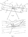
- a porous layer 5 is arranged inside the reservoir 4 of the ion-selective sensor 6.
- Figs 6, 7 and 8 show the cross-section of such an ion-selective sensor 6 comprising a porous layer 5.
- Fig. 6 corresponds to the cross-section of fig. 4 according to the line A-A'
- fig. 7 corresponds to the cross-section of fig.4 according to the line B-B'
- fig.8 corresponds to the cross-section of fig.4 according to the line C-C'.
- Said porous layer 5 may be arranged in said recess 4a of the first substrate 100 before assembly with the second substrate 200.
- the porous layer 5 may be arranged to a recess 4b of the second substrate 200 before said assembly.
- the thickness of the porous layer 5 may be smaller or equal to the depth of said recesses.
- a 3D view of an embodiment is shown wherein the first liquid membrane micro channel 3 is connected to the porous layer 5 arranged in the reservoir 4, allowing to soak said porous layer 5 with the liquid membrane solution provided by the liquid membrane micro channel 3.
- the analyte and electrolyte solutions are brought into contact with the liquid membrane located in reservoir 4 after the stabilisation of the liquid membrane and said analyte and electrolyte solutions stay separated by the porous layer soaked with said liquid membrane solution.
- the materials for the porous layer 5 are preferably chosen among plastic porous materials.
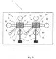
- two ion-sensors may be arranged to the analyte micro channel 2, as illustrated in fig. 11 .
- the two electrolyte micro channels 1, 11 may have the same geometry or they may have a different geometry. They may also draw the same electrolyte solution or a different electrolyte solution.
- the two liquid membrane micro channels 3, 31 may have the same geometry or they may have a different geometry. They may also draw the same liquid membrane solution or a different liquid membrane solution.
- the two porous layers 5, 50 arranged into the two reservoirs 4, 40 may have the same geometry or they may have a different geometry and the materials used for the tow porous layers 5, 50 may be different.
- An example of a system for executing the method of the invention relates also to an ion-sensor system, differing from the ion-sensor device 7 of fig. 11 , in that more than 2 ion-sensors are arranged to the same analyte micro channel 2.
- the analyte micro channel 2 must not be necessarily a straight micro channel and may be arranged as a curve on the surface of said second substrate 200.
- a gas is flown in the electrolyte micro channel 1 and the analyte micro channel 3, prior to the introduction of the liquid membrane solution in the liquid membrane micro channel 3 and the reservoir 4, this in order to keep in place the liquid membrane when introducing the analyte and electrolyte solution, and to avoid the mixing of the liquid membrane, the analyte solution and the electrolyte solution.
- the realisation of the micro channels and their inlets and outlets may be realised in different arrangements that the ones explained.
- the inlets and outlets may be formed by partially structuring two portions, one portion being structured in the first substrate 100 and the second portion being structured in the second substrate 200 and at the same time the corresponding micro channels may be structured in one or both of first 100 and second 200 substrate but always so that after assembly of the first 100 and second 200 substrate the micro channels comprise an inlet and an outlet.
Landscapes
- Chemical & Material Sciences (AREA)
- Life Sciences & Earth Sciences (AREA)
- Health & Medical Sciences (AREA)
- Biochemistry (AREA)
- Chemical Kinetics & Catalysis (AREA)
- Electrochemistry (AREA)
- Physics & Mathematics (AREA)
- Analytical Chemistry (AREA)
- Molecular Biology (AREA)
- General Health & Medical Sciences (AREA)
- General Physics & Mathematics (AREA)
- Immunology (AREA)
- Pathology (AREA)
- Investigating Or Analyzing Materials By The Use Of Electric Means (AREA)
- Automatic Analysis And Handling Materials Therefor (AREA)
- Measurement Of The Respiration, Hearing Ability, Form, And Blood Characteristics Of Living Organisms (AREA)
Claims (7)
- Verfahren zum Messen der lonenkonzentration einer Analytlösung, den folgenden Schritt umfassend:- Bereitstellen eines mikromaschinell bearbeiteten Chips, umfassend einen Analyt-Mikrokanal (2), der dazu eingerichtet ist, eine Analytlösung anzusaugen, und einen ersten Flüssigmembran-Mikrokanal (3), der dazu eingerichtet ist, eine Flüssigmembranlösung anzusaugen, und einen ersten Elektrolyt-Mikrokanal (1), der dazu eingerichtet ist, eine Elektrolytlösung anzusaugen, wobei der mikromaschinell bearbeitete Chip ferner Folgendes umfasst:- ein erstes Substrat (100), das einen ersten Elektrolyt-Mikrokanal (1) umfasst, der in eine seiner Oberflächen integriert ist, dazu eingerichtet, eine Elektrolytlösung anzusaugen; wobei der erste Elektrolyt-Mikrokanal (1) an seinen äußersten Enden derart strukturiert ist, dass er eine Öffnung präsentiert, die für einen Einlass (10) vorgesehen ist, und eine weitere Öffnung, die für einen Auslass (12) der Elektrolytlösung vorgesehen ist;- mindestens eine Metallstreifenschicht (15), die mindestens zwei Abschnitte umfasst, von denen ein erster Abschnitt (15a) auf dem ersten Substrat (100) abgeschieden ist und ein zweiter Abschnitt (15b) in dem ersten Elektrolyt-Mikrokanal (1) abgeschieden ist, wobei die Abschnitte elektrisch verbunden sind;- ein zweites Substrat (200), das auf einer seiner Oberflächen, gegenüber der Oberfläche des ersten Substrates (100) angeordnet, den Analyt-Mikrokanal (2) und den ersten Flüssigmembran-Mikrokanal (3) umfasst, wobei der Analyt-Mikrokanal (2) an seinen äußersten Enden derart strukturiert ist, dass er eine Öffnung präsentiert, die für einen Einlass (20) vorgesehen ist, und eine weitere Öffnung, die für einen Auslass (22) der Analytlösung vorgesehen ist, und der erste Flüssigmembran-Mikrokanal (3) an seinen äußersten Enden derart strukturiert ist, dass er eine Öffnung präsentiert, die für einen Einlass (30) vorgesehen ist, und eine weitere Öffnung, die für einen Auslass (32) der Flüssigmembran vorgesehen ist;wobei das erste Substrat (100) und das zweite Substrat (200) den Analyt-Mikrokanal (2), den ersten Elektrolyt-Mikrokanal (1) und den ersten Flüssigmembran-Mikrokanal (3) verschließen und ein erstes Reservoir (4) an der Grenzfläche zwischen dem Analyt-Mikrokanal (2) und dem ersten Elektrolyt-Mikrokanal (1) gebildet ist, wobei das erste Reservoir (4) mit dem Analyt-Mikrokanal (2), dem ersten Elektrolyt-Mikrokanal (1) und dem ersten Flüssigmembran-Mikrokanal (3) verbunden ist, wobei das erste Reservoir (4) eine erste poröse Schicht (5) umfasst, die eine Flüssigmembran hält, die die Analytlösung und die Elektrolytlösung trennt, wobei die Analytlösung und die Elektrolytlösung in ihren jeweiligen Mikrokanal gesaugt werden, wobei das Verfahren außerdem die folgenden Schritte umfasst:- Zugeben einer Flüssigmembran zu dem Einlass (30) des ersten Flüssigmembran-Mikrokanals (3);- Zulassen, dass die Flüssigmembran mittels Kapillarwirkung durch den ersten Flüssigmembran-Mikrokanal (3) zu dem Reservoir (4) transportiert wird;- Zulassen, dass die Flüssigmembran die poröse Schicht (5) durchtränkt;- Warten, bis die Flüssigmembran innerhalb der porösen Schicht (5) ein Gleichgewicht erreicht;- Pumpen der Elektrolytlösung in den Elektrolyt-Mikrokanal (1);- Pumpen eine Vorkonditionierungslösung in den Analyt-Mikrokanal (2);- Warten für einige Stunden, typischerweise über Nacht, bis die drei Flüssigphasen ein Gleichgewicht erreichen;- vor dem Starten der Messungen Erneuern der Analytlösung in dem Analyt-Mikrokanal und Erneuern der internen Elektrolytlösung in dem ersten Elektrolyt-Mikrokanal (1) durch Pumpen frischer Lösung in ihre jeweiligen Kanäle;- Starten eines Kalibrierungszyklus durch Pumpen einer oder mehrerer Kalibrierungslösungen, die eine genau bestimmte Zusammensetzung und lonenkonzentrationen einer spezifischen lonenspezies umfassen, in den Analyt-Mikrokanal (2);- nach dem Ende des Kalibrierungszyklus Starten eines Spülzyklus durch Pumpen einer Spüllösung in den Analyt-Mikrokanal (2);- Pumpen der Analytlösung in den Analyt-Kanal und Durchführen der lonenkonzentrationsmessung der Analytlösung;- bei Bedarf Wiederholen der Messungsschritte mit anderen Analytlösungen;- nach den Ende des Messungszyklus Starten eines Spülzyklus durch Pumpen einer Spüllösung in den Analyt-Mikrokanal (2).
- Verfahren nach Anspruch 1, wobei der erste Flüssigmembran-Mikrokanal (3) und/oder der Analyt-Mikrokanal (2) zwei Abschnitte umfasst/umfassen, wobei ein Abschnitt auf dem ersten Substrat(100) strukturiert ist und ein zweiter Abschnitt auf dem zweiten Substrat (200) strukturiert ist.
- Verfahren nach Anspruch 1, wobei das erste Reservoir (4) eine erste Aussparung (4a) ist, die in dem ersten Substrat (100) angeordnet ist.
- Verfahren nach Anspruch 1, wobei das erste Reservoir (4) eine zweite Aussparung (4b) ist, die in dem zweiten Substrat (200) angeordnet ist.
- Verfahren nach Anspruch 1, wobei das erste Reservoir (4) eine erste Aussparung (4a) umfasst, die in dem ersten Substrat (100) angeordnet ist, und eine zweite Aussparung (4b) in dem zweiten Substrat (200) umfasst, wobei die zweite Aussparung (4b) gegenüber der ersten Aussparung (4a) angeordnet ist.
- Verfahren nach einem der Ansprüche 1 bis 5, wobei der erste Elektrolyt-Mikrokanal (1), der erste Flüssigmembran-Mikrokanal (3) und der Analyt-Mikrokanal (2) mit dem ersten Reservoir (4) verbunden sind und in einem Winkel zwischen jeweils dem ersten Elektrolyt-Mikrokanal (1), dem ersten Flüssigmembran-Mikrokanal (3) und dem Analyt-Mikrokanal (2) angeordnet sind.
- Verfahren nach einem der Ansprüche 1 bis 6, wobei die Substrate aus einem beliebigen strukturierbaren Material hergestellt sind, vorzugsweise einem Polymermaterial.
Applications Claiming Priority (2)
| Application Number | Priority Date | Filing Date | Title |
|---|---|---|---|
| US201261683852P | 2012-08-16 | 2012-08-16 | |
| PCT/EP2013/067045 WO2014027051A1 (en) | 2012-08-16 | 2013-08-14 | Micro-fluidic ion-selective sensor and measurement of an analyte using the same |
Publications (2)
| Publication Number | Publication Date |
|---|---|
| EP2885633A1 EP2885633A1 (de) | 2015-06-24 |
| EP2885633B1 true EP2885633B1 (de) | 2020-02-12 |
Family
ID=49035545
Family Applications (1)
| Application Number | Title | Priority Date | Filing Date |
|---|---|---|---|
| EP13753129.9A Active EP2885633B1 (de) | 2012-08-16 | 2013-08-14 | Verfahren zur Messung der Ionenkonzentration eines Analyten mit einem mikromechanischen Chip eines ionenselektiven Sensors |
Country Status (4)
| Country | Link |
|---|---|
| US (1) | US20150219589A1 (de) |
| EP (1) | EP2885633B1 (de) |
| BR (1) | BR112015003243A2 (de) |
| WO (1) | WO2014027051A1 (de) |
Families Citing this family (3)
| Publication number | Priority date | Publication date | Assignee | Title |
|---|---|---|---|---|
| CN108139349B (zh) * | 2015-08-07 | 2021-01-29 | 夫琅和费美国公司 | 一种检测流体中的痕量金属的系统 |
| EP3336528A1 (de) * | 2016-12-16 | 2018-06-20 | Stichting IMEC Nederland | Ionenselektive elektrode |
| CN110997145B (zh) * | 2018-08-01 | 2022-05-13 | 京东方科技集团股份有限公司 | 微通道结构、传感器、微流体装置、芯片实验室装置、以及制造微通道结构的方法 |
Citations (1)
| Publication number | Priority date | Publication date | Assignee | Title |
|---|---|---|---|---|
| US20030112013A1 (en) * | 1999-12-08 | 2003-06-19 | Andreas Manz | Potentiometric sensor |
Family Cites Families (5)
| Publication number | Priority date | Publication date | Assignee | Title |
|---|---|---|---|---|
| US3737379A (en) * | 1971-04-28 | 1973-06-05 | Univ Duke | Instantaneous measurement of potassium and other specific ion activities |
| US5846396A (en) * | 1994-11-10 | 1998-12-08 | Sarnoff Corporation | Liquid distribution system |
| KR100480338B1 (ko) * | 2002-08-08 | 2005-03-30 | 한국전자통신연구원 | 극소량의 유체제어를 위한 미세 유체제어소자 |
| US20090120796A1 (en) * | 2007-09-26 | 2009-05-14 | Jongyoon Han | Electrokinetic concentration device and methods of use thereof |
| KR20100083029A (ko) * | 2009-01-12 | 2010-07-21 | 삼성전자주식회사 | 전기화학적 방법에 의하여 시료에 포함된 전해질 검출이 가능한 디스크형 미세유동장치 |
-
2013
- 2013-08-14 US US14/421,399 patent/US20150219589A1/en not_active Abandoned
- 2013-08-14 EP EP13753129.9A patent/EP2885633B1/de active Active
- 2013-08-14 WO PCT/EP2013/067045 patent/WO2014027051A1/en not_active Ceased
- 2013-08-14 BR BR112015003243A patent/BR112015003243A2/pt not_active IP Right Cessation
Patent Citations (1)
| Publication number | Priority date | Publication date | Assignee | Title |
|---|---|---|---|---|
| US20030112013A1 (en) * | 1999-12-08 | 2003-06-19 | Andreas Manz | Potentiometric sensor |
Also Published As
| Publication number | Publication date |
|---|---|
| EP2885633A1 (de) | 2015-06-24 |
| US20150219589A1 (en) | 2015-08-06 |
| WO2014027051A1 (en) | 2014-02-20 |
| BR112015003243A2 (pt) | 2018-07-31 |
Similar Documents
| Publication | Publication Date | Title |
|---|---|---|
| EP2363705B1 (de) | Mikromechanische Referenzelektrode mit einer Flüssigkeitsbrücke | |
| EP3088879B1 (de) | Verfahren zur herstellung einer bezugselektrode mit einer porenmembran | |
| US4891120A (en) | Chromatographic separation device | |
| US7265348B2 (en) | Apparatus for dispensing a sample in electrospray mass spectrometers | |
| US20230137889A1 (en) | Electrochemical sensor with opening between solid elements | |
| WO2007087632A2 (en) | Microscale electrochemical cell and methods incorporating the cell | |
| Noh et al. | Nanoporous platinum solid-state reference electrode with layer-by-layer polyelectrolyte junction for pH sensing chip | |
| US20150219589A1 (en) | Micro-fluidic ion-selective sensor and measurement of an analyte using the same | |
| US10094798B2 (en) | Reference electrode and an arrangement for an electrochemical measurement | |
| JP2023160684A (ja) | マイクロ分析チップ | |
| US20240192163A1 (en) | Sensor device with functionalized fluid cavity | |
| US20250083142A1 (en) | Multiplexed nucleic acid amplification test on semiconductor substrate | |
| US20030112013A1 (en) | Potentiometric sensor | |
| US20230184713A1 (en) | Integrated circuit FLUID sensor | |
| JP4216846B2 (ja) | 微小電気化学測定用電極および電気化学測定法 | |
| EP3336528A1 (de) | Ionenselektive elektrode | |
| WO2024129639A1 (en) | Sensor device with functionalized fluid cavity | |
| EP4634655A1 (de) | Sensorvorrichtung mit funktionalisiertem flüssigkeitshohlraum | |
| WO2013135733A1 (en) | Disposable system for ion selective electrodes for long term monitoring | |
| CN107850565A (zh) | 基于差分测量的离子传感器 | |
| Bani-Yaseen | Integrated Microfluidic MEMS and Their Biomedical Applications | |
| Guenat | Micro total analysis systems for coulometric and volumetric nanotitrations | |
| PL196296B1 (pl) | Elektroda jonoselektywna i sposób jej wytwarzania |
Legal Events
| Date | Code | Title | Description |
|---|---|---|---|
| PUAI | Public reference made under article 153(3) epc to a published international application that has entered the european phase |
Free format text: ORIGINAL CODE: 0009012 |
|
| 17P | Request for examination filed |
Effective date: 20150316 |
|
| AK | Designated contracting states |
Kind code of ref document: A1 Designated state(s): AL AT BE BG CH CY CZ DE DK EE ES FI FR GB GR HR HU IE IS IT LI LT LU LV MC MK MT NL NO PL PT RO RS SE SI SK SM TR |
|
| AX | Request for extension of the european patent |
Extension state: BA ME |
|
| DAX | Request for extension of the european patent (deleted) | ||
| RIC1 | Information provided on ipc code assigned before grant |
Ipc: G01N 27/333 20060101AFI20190515BHEP Ipc: B01L 3/00 20060101ALN20190515BHEP |
|
| GRAP | Despatch of communication of intention to grant a patent |
Free format text: ORIGINAL CODE: EPIDOSNIGR1 |
|
| STAA | Information on the status of an ep patent application or granted ep patent |
Free format text: STATUS: GRANT OF PATENT IS INTENDED |
|
| RIC1 | Information provided on ipc code assigned before grant |
Ipc: G01N 27/333 20060101AFI20190517BHEP Ipc: B01L 3/00 20060101ALN20190517BHEP |
|
| INTG | Intention to grant announced |
Effective date: 20190624 |
|
| INTG | Intention to grant announced |
Effective date: 20190625 |
|
| RIN1 | Information on inventor provided before grant (corrected) |
Inventor name: GENERELLI, SILVIA Inventor name: BARBE, LAURENT |
|
| GRAJ | Information related to disapproval of communication of intention to grant by the applicant or resumption of examination proceedings by the epo deleted |
Free format text: ORIGINAL CODE: EPIDOSDIGR1 |
|
| GRAL | Information related to payment of fee for publishing/printing deleted |
Free format text: ORIGINAL CODE: EPIDOSDIGR3 |
|
| GRAS | Grant fee paid |
Free format text: ORIGINAL CODE: EPIDOSNIGR3 |
|
| STAA | Information on the status of an ep patent application or granted ep patent |
Free format text: STATUS: REQUEST FOR EXAMINATION WAS MADE |
|
| INTC | Intention to grant announced (deleted) | ||
| RIC1 | Information provided on ipc code assigned before grant |
Ipc: B01L 3/00 20060101ALN20191028BHEP Ipc: G01N 27/333 20060101AFI20191028BHEP |
|
| GRAP | Despatch of communication of intention to grant a patent |
Free format text: ORIGINAL CODE: EPIDOSNIGR1 |
|
| STAA | Information on the status of an ep patent application or granted ep patent |
Free format text: STATUS: GRANT OF PATENT IS INTENDED |
|
| GRAA | (expected) grant |
Free format text: ORIGINAL CODE: 0009210 |
|
| STAA | Information on the status of an ep patent application or granted ep patent |
Free format text: STATUS: THE PATENT HAS BEEN GRANTED |
|
| INTG | Intention to grant announced |
Effective date: 20191218 |
|
| AK | Designated contracting states |
Kind code of ref document: B1 Designated state(s): AL AT BE BG CH CY CZ DE DK EE ES FI FR GB GR HR HU IE IS IT LI LT LU LV MC MK MT NL NO PL PT RO RS SE SI SK SM TR |
|
| REG | Reference to a national code |
Ref country code: GB Ref legal event code: FG4D |
|
| REG | Reference to a national code |
Ref country code: CH Ref legal event code: EP |
|
| REG | Reference to a national code |
Ref country code: AT Ref legal event code: REF Ref document number: 1232811 Country of ref document: AT Kind code of ref document: T Effective date: 20200215 |
|
| REG | Reference to a national code |
Ref country code: IE Ref legal event code: FG4D |
|
| REG | Reference to a national code |
Ref country code: DE Ref legal event code: R096 Ref document number: 602013065706 Country of ref document: DE |
|
| REG | Reference to a national code |
Ref country code: CH Ref legal event code: NV Representative=s name: NOVAGRAAF INTERNATIONAL SA, CH |
|
| PG25 | Lapsed in a contracting state [announced via postgrant information from national office to epo] |
Ref country code: RS Free format text: LAPSE BECAUSE OF FAILURE TO SUBMIT A TRANSLATION OF THE DESCRIPTION OR TO PAY THE FEE WITHIN THE PRESCRIBED TIME-LIMIT Effective date: 20200212 Ref country code: FI Free format text: LAPSE BECAUSE OF FAILURE TO SUBMIT A TRANSLATION OF THE DESCRIPTION OR TO PAY THE FEE WITHIN THE PRESCRIBED TIME-LIMIT Effective date: 20200212 Ref country code: NO Free format text: LAPSE BECAUSE OF FAILURE TO SUBMIT A TRANSLATION OF THE DESCRIPTION OR TO PAY THE FEE WITHIN THE PRESCRIBED TIME-LIMIT Effective date: 20200512 |
|
| REG | Reference to a national code |
Ref country code: LT Ref legal event code: MG4D |
|
| REG | Reference to a national code |
Ref country code: NL Ref legal event code: MP Effective date: 20200212 |
|
| PG25 | Lapsed in a contracting state [announced via postgrant information from national office to epo] |
Ref country code: SE Free format text: LAPSE BECAUSE OF FAILURE TO SUBMIT A TRANSLATION OF THE DESCRIPTION OR TO PAY THE FEE WITHIN THE PRESCRIBED TIME-LIMIT Effective date: 20200212 Ref country code: LV Free format text: LAPSE BECAUSE OF FAILURE TO SUBMIT A TRANSLATION OF THE DESCRIPTION OR TO PAY THE FEE WITHIN THE PRESCRIBED TIME-LIMIT Effective date: 20200212 Ref country code: HR Free format text: LAPSE BECAUSE OF FAILURE TO SUBMIT A TRANSLATION OF THE DESCRIPTION OR TO PAY THE FEE WITHIN THE PRESCRIBED TIME-LIMIT Effective date: 20200212 Ref country code: BG Free format text: LAPSE BECAUSE OF FAILURE TO SUBMIT A TRANSLATION OF THE DESCRIPTION OR TO PAY THE FEE WITHIN THE PRESCRIBED TIME-LIMIT Effective date: 20200512 Ref country code: IS Free format text: LAPSE BECAUSE OF FAILURE TO SUBMIT A TRANSLATION OF THE DESCRIPTION OR TO PAY THE FEE WITHIN THE PRESCRIBED TIME-LIMIT Effective date: 20200612 Ref country code: GR Free format text: LAPSE BECAUSE OF FAILURE TO SUBMIT A TRANSLATION OF THE DESCRIPTION OR TO PAY THE FEE WITHIN THE PRESCRIBED TIME-LIMIT Effective date: 20200513 |
|
| PG25 | Lapsed in a contracting state [announced via postgrant information from national office to epo] |
Ref country code: NL Free format text: LAPSE BECAUSE OF FAILURE TO SUBMIT A TRANSLATION OF THE DESCRIPTION OR TO PAY THE FEE WITHIN THE PRESCRIBED TIME-LIMIT Effective date: 20200212 |
|
| PG25 | Lapsed in a contracting state [announced via postgrant information from national office to epo] |
Ref country code: SK Free format text: LAPSE BECAUSE OF FAILURE TO SUBMIT A TRANSLATION OF THE DESCRIPTION OR TO PAY THE FEE WITHIN THE PRESCRIBED TIME-LIMIT Effective date: 20200212 Ref country code: RO Free format text: LAPSE BECAUSE OF FAILURE TO SUBMIT A TRANSLATION OF THE DESCRIPTION OR TO PAY THE FEE WITHIN THE PRESCRIBED TIME-LIMIT Effective date: 20200212 Ref country code: CZ Free format text: LAPSE BECAUSE OF FAILURE TO SUBMIT A TRANSLATION OF THE DESCRIPTION OR TO PAY THE FEE WITHIN THE PRESCRIBED TIME-LIMIT Effective date: 20200212 Ref country code: DK Free format text: LAPSE BECAUSE OF FAILURE TO SUBMIT A TRANSLATION OF THE DESCRIPTION OR TO PAY THE FEE WITHIN THE PRESCRIBED TIME-LIMIT Effective date: 20200212 Ref country code: ES Free format text: LAPSE BECAUSE OF FAILURE TO SUBMIT A TRANSLATION OF THE DESCRIPTION OR TO PAY THE FEE WITHIN THE PRESCRIBED TIME-LIMIT Effective date: 20200212 Ref country code: PT Free format text: LAPSE BECAUSE OF FAILURE TO SUBMIT A TRANSLATION OF THE DESCRIPTION OR TO PAY THE FEE WITHIN THE PRESCRIBED TIME-LIMIT Effective date: 20200705 Ref country code: EE Free format text: LAPSE BECAUSE OF FAILURE TO SUBMIT A TRANSLATION OF THE DESCRIPTION OR TO PAY THE FEE WITHIN THE PRESCRIBED TIME-LIMIT Effective date: 20200212 Ref country code: LT Free format text: LAPSE BECAUSE OF FAILURE TO SUBMIT A TRANSLATION OF THE DESCRIPTION OR TO PAY THE FEE WITHIN THE PRESCRIBED TIME-LIMIT Effective date: 20200212 Ref country code: SM Free format text: LAPSE BECAUSE OF FAILURE TO SUBMIT A TRANSLATION OF THE DESCRIPTION OR TO PAY THE FEE WITHIN THE PRESCRIBED TIME-LIMIT Effective date: 20200212 |
|
| REG | Reference to a national code |
Ref country code: DE Ref legal event code: R097 Ref document number: 602013065706 Country of ref document: DE |
|
| REG | Reference to a national code |
Ref country code: AT Ref legal event code: MK05 Ref document number: 1232811 Country of ref document: AT Kind code of ref document: T Effective date: 20200212 |
|
| PLBE | No opposition filed within time limit |
Free format text: ORIGINAL CODE: 0009261 |
|
| STAA | Information on the status of an ep patent application or granted ep patent |
Free format text: STATUS: NO OPPOSITION FILED WITHIN TIME LIMIT |
|
| 26N | No opposition filed |
Effective date: 20201113 |
|
| PG25 | Lapsed in a contracting state [announced via postgrant information from national office to epo] |
Ref country code: AT Free format text: LAPSE BECAUSE OF FAILURE TO SUBMIT A TRANSLATION OF THE DESCRIPTION OR TO PAY THE FEE WITHIN THE PRESCRIBED TIME-LIMIT Effective date: 20200212 Ref country code: IT Free format text: LAPSE BECAUSE OF FAILURE TO SUBMIT A TRANSLATION OF THE DESCRIPTION OR TO PAY THE FEE WITHIN THE PRESCRIBED TIME-LIMIT Effective date: 20200212 |
|
| PG25 | Lapsed in a contracting state [announced via postgrant information from national office to epo] |
Ref country code: SI Free format text: LAPSE BECAUSE OF FAILURE TO SUBMIT A TRANSLATION OF THE DESCRIPTION OR TO PAY THE FEE WITHIN THE PRESCRIBED TIME-LIMIT Effective date: 20200212 Ref country code: PL Free format text: LAPSE BECAUSE OF FAILURE TO SUBMIT A TRANSLATION OF THE DESCRIPTION OR TO PAY THE FEE WITHIN THE PRESCRIBED TIME-LIMIT Effective date: 20200212 |
|
| PG25 | Lapsed in a contracting state [announced via postgrant information from national office to epo] |
Ref country code: MC Free format text: LAPSE BECAUSE OF FAILURE TO SUBMIT A TRANSLATION OF THE DESCRIPTION OR TO PAY THE FEE WITHIN THE PRESCRIBED TIME-LIMIT Effective date: 20200212 |
|
| PG25 | Lapsed in a contracting state [announced via postgrant information from national office to epo] |
Ref country code: LU Free format text: LAPSE BECAUSE OF NON-PAYMENT OF DUE FEES Effective date: 20200814 |
|
| REG | Reference to a national code |
Ref country code: BE Ref legal event code: MM Effective date: 20200831 |
|
| PG25 | Lapsed in a contracting state [announced via postgrant information from national office to epo] |
Ref country code: IE Free format text: LAPSE BECAUSE OF NON-PAYMENT OF DUE FEES Effective date: 20200814 Ref country code: BE Free format text: LAPSE BECAUSE OF NON-PAYMENT OF DUE FEES Effective date: 20200831 |
|
| PGFP | Annual fee paid to national office [announced via postgrant information from national office to epo] |
Ref country code: CH Payment date: 20210923 Year of fee payment: 9 Ref country code: FR Payment date: 20210831 Year of fee payment: 9 |
|
| PGFP | Annual fee paid to national office [announced via postgrant information from national office to epo] |
Ref country code: DE Payment date: 20210830 Year of fee payment: 9 Ref country code: GB Payment date: 20210831 Year of fee payment: 9 |
|
| PG25 | Lapsed in a contracting state [announced via postgrant information from national office to epo] |
Ref country code: TR Free format text: LAPSE BECAUSE OF FAILURE TO SUBMIT A TRANSLATION OF THE DESCRIPTION OR TO PAY THE FEE WITHIN THE PRESCRIBED TIME-LIMIT Effective date: 20200212 Ref country code: MT Free format text: LAPSE BECAUSE OF FAILURE TO SUBMIT A TRANSLATION OF THE DESCRIPTION OR TO PAY THE FEE WITHIN THE PRESCRIBED TIME-LIMIT Effective date: 20200212 Ref country code: CY Free format text: LAPSE BECAUSE OF FAILURE TO SUBMIT A TRANSLATION OF THE DESCRIPTION OR TO PAY THE FEE WITHIN THE PRESCRIBED TIME-LIMIT Effective date: 20200212 |
|
| PG25 | Lapsed in a contracting state [announced via postgrant information from national office to epo] |
Ref country code: MK Free format text: LAPSE BECAUSE OF FAILURE TO SUBMIT A TRANSLATION OF THE DESCRIPTION OR TO PAY THE FEE WITHIN THE PRESCRIBED TIME-LIMIT Effective date: 20200212 Ref country code: AL Free format text: LAPSE BECAUSE OF FAILURE TO SUBMIT A TRANSLATION OF THE DESCRIPTION OR TO PAY THE FEE WITHIN THE PRESCRIBED TIME-LIMIT Effective date: 20200212 |
|
| REG | Reference to a national code |
Ref country code: DE Ref legal event code: R119 Ref document number: 602013065706 Country of ref document: DE |
|
| REG | Reference to a national code |
Ref country code: CH Ref legal event code: PL |
|
| GBPC | Gb: european patent ceased through non-payment of renewal fee |
Effective date: 20220814 |
|
| PG25 | Lapsed in a contracting state [announced via postgrant information from national office to epo] |
Ref country code: LI Free format text: LAPSE BECAUSE OF NON-PAYMENT OF DUE FEES Effective date: 20220831 Ref country code: CH Free format text: LAPSE BECAUSE OF NON-PAYMENT OF DUE FEES Effective date: 20220831 |
|
| PG25 | Lapsed in a contracting state [announced via postgrant information from national office to epo] |
Ref country code: FR Free format text: LAPSE BECAUSE OF NON-PAYMENT OF DUE FEES Effective date: 20220831 Ref country code: DE Free format text: LAPSE BECAUSE OF NON-PAYMENT OF DUE FEES Effective date: 20230301 |
|
| PG25 | Lapsed in a contracting state [announced via postgrant information from national office to epo] |
Ref country code: GB Free format text: LAPSE BECAUSE OF NON-PAYMENT OF DUE FEES Effective date: 20220814 |