EP2885484B1 - Achsenwartungsvorrichtung, systeme und verfahren - Google Patents
Achsenwartungsvorrichtung, systeme und verfahren Download PDFInfo
- Publication number
- EP2885484B1 EP2885484B1 EP12745737.2A EP12745737A EP2885484B1 EP 2885484 B1 EP2885484 B1 EP 2885484B1 EP 12745737 A EP12745737 A EP 12745737A EP 2885484 B1 EP2885484 B1 EP 2885484B1
- Authority
- EP
- European Patent Office
- Prior art keywords
- housing
- rollers
- axis
- borehole
- rotation
- Prior art date
- Legal status (The legal status is an assumption and is not a legal conclusion. Google has not performed a legal analysis and makes no representation as to the accuracy of the status listed.)
- Not-in-force
Links
Images


Classifications
-
- E—FIXED CONSTRUCTIONS
- E21—EARTH DRILLING; MINING
- E21B—EARTH DRILLING, e.g. DEEP DRILLING; OBTAINING OIL, GAS, WATER, SOLUBLE OR MELTABLE MATERIALS OR A SLURRY OF MINERALS FROM WELLS
- E21B17/00—Drilling rods or pipes; Flexible drill strings; Kellies; Drill collars; Sucker rods; Cables; Casings; Tubings
- E21B17/10—Wear protectors; Centralising devices, e.g. stabilisers
- E21B17/1057—Centralising devices with rollers or with a relatively rotating sleeve
-
- E—FIXED CONSTRUCTIONS
- E21—EARTH DRILLING; MINING
- E21B—EARTH DRILLING, e.g. DEEP DRILLING; OBTAINING OIL, GAS, WATER, SOLUBLE OR MELTABLE MATERIALS OR A SLURRY OF MINERALS FROM WELLS
- E21B17/00—Drilling rods or pipes; Flexible drill strings; Kellies; Drill collars; Sucker rods; Cables; Casings; Tubings
- E21B17/10—Wear protectors; Centralising devices, e.g. stabilisers
- E21B17/1014—Flexible or expansible centering means, e.g. with pistons pressing against the wall of the well
-
- E—FIXED CONSTRUCTIONS
- E21—EARTH DRILLING; MINING
- E21B—EARTH DRILLING, e.g. DEEP DRILLING; OBTAINING OIL, GAS, WATER, SOLUBLE OR MELTABLE MATERIALS OR A SLURRY OF MINERALS FROM WELLS
- E21B19/00—Handling rods, casings, tubes or the like outside the borehole, e.g. in the derrick; Apparatus for feeding the rods or cables
- E21B19/16—Connecting or disconnecting pipe couplings or joints
-
- E—FIXED CONSTRUCTIONS
- E21—EARTH DRILLING; MINING
- E21B—EARTH DRILLING, e.g. DEEP DRILLING; OBTAINING OIL, GAS, WATER, SOLUBLE OR MELTABLE MATERIALS OR A SLURRY OF MINERALS FROM WELLS
- E21B47/00—Survey of boreholes or wells
- E21B47/09—Locating or determining the position of objects in boreholes or wells, e.g. the position of an extending arm; Identifying the free or blocked portions of pipes
Definitions
- Measurements made in a borehole are typically performed to attain this understanding, to identify the composition and distribution of materials that surround the measurement device down hole.
- measurement tool vibrations not only reduce the reliability and increase the cost of down hole tools, but also lower the quality of their measurements.
- some of the measurement technologies that are used including NMR (nuclear magnetic resonance) imaging and LWD (logging while drilling) sonic measurements, are sensitive to the vibration caused by drilling and other down hole activities.
- a dynamic centralizer with feedback control sensors may be used to stabilize the rotating axis of the housing (e.g., of a down hole tool) before taking data.
- Various embodiments provide solid contact between the centralizer and the borehole surface, while permitting two degrees of movement freedom - vertically, along the chosen longitudinal axis, and azimuthally, around the same axis.
- one or more omnidirectional wheels having one or more sets of rollers may be employed.
- Those of ordinary skill in the art are familiar with this type of wheel.
- Others that desire additional information may refer to " An Omnidirectional Wheel Based on Reuleaux Triangle", by Brunhorn et al., RoboCup 2006: Robot Soccer World Cup X, Bremen, pp. 516-512, June 2006 .
- Omnidirectional wheels can be purchased from several suppliers, including AndyMark Inc. of Kokomo, IN. Using such wheels according the manner described herein provides a platform to stabilize the tool rotational axis, improving measurement quality and other aspects of down hole performance.
- omnidirectional wheels can be used to accommodate the advancing motions of down hole tools, with feedback control and dampers to quickly stabilize the tool housing rotational axis against vibration, such as drilling vibration. Because omnidirectional wheels allow for motion with two degrees of freedom, substantial contact between the borehole wall and the centralizer can be maintained without slipping.
- feedback control sensors on the centralizer arm(s) can be used to stabilize the rotating axis of the housing to improve NMR and sonic measurement quality, for example.
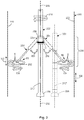
- FIGs. 1A-1B illustrate sets of rollers 82 in perspective view, according to various embodiments of the invention.
- an omnidirectional wheel 80', 80" has a set of individual rollers 82 which share a primary axis 84 of rotation, so the wheel 80', 80" is capable of moving in the longitudinal direction102.
- the rollers 82 also share a secondary axis 86 of rotation, providing the wheel 80', 80" with the capability of moving in the azimuthal direction 104,
- a bearing 88 such as a set of ball bearings (see FIG. 1A ) or a sleeve bearing (see FIG. 2A ) may be used to support motion around the secondary axis 86. In this way, the wheel 80', 80" enjoys two degrees of movement freedom.
- FIG. 1A a set of compliantly-curved spokes 100 are used to couple the primary and second axes 84, 86 of rotation.
- axles 106 perhaps made from spring steel, are located substantially in line with the primary axis 84 of rotation and are used to compliantly mount individual rollers 82 to a rigid (e.g., made of metal) or compliant (e.g., made of rubber, fiber-composite, plastic, or polymer material) frame 108.
- a rigid e.g., made of metal
- compliant e.g., made of rubber, fiber-composite, plastic, or polymer material
- FIG. 2 illustrates a side view of an apparatus 200 comprising extensible arms 204 attached to a housing 202 and sets of rollers according to various embodiments of the invention.
- a potential LWD implementation is shown using multiple omniwheels 80 to construct an actively-controlled centralizer.
- the arms 204 can swing out at the same, or different angles 206 with respect to housing 202.
- tool rotation dominates, therefore, the primary alignment axis 212' for the housing 202 centerline parallels (and coincides with) the longitudinal axis 250 of the borehole 220.
- Off-center rotation can be achieved (e.g., see the dashed housing 202 location, where the housing centerline 212" is aligned to rotate about the borehole axis 250) by individually adjusting the angle 206 of each arm 204, and/or the amount of its linear extension, which will allow drilling a bigger size borehole with a smaller size bit, or maintaining a constant tool offset distance within the borehole 220.
- Different types of sensors can be used to provide information regarding the radial acceleration about the housing longitudinal axis 212' and the angle 206 of the arms 204. Forces on the arms 204 and the rotating speed of the housing 202 about the axis 212' can be used in feedback loops to minimize the radial acceleration and displacement of the tool axis 212'.
- a damping and spring mechanism can also be incorporated into each arm 204 to mechanically smooth the arm reaction to borehole rugosity on the borehole surface 222, allowing for the moment of inertia to take control.
- tool vibrations may be better controlled when the wheel (and rollers) travel along the largest virtual circle that fits within the hole, rather than allowing the wheel (and rollers) to follow the borehole surface profile.
- brakes B and a clutch C can be used to reduce or halt rotation of the roller sets within the wheels 80', 80". This enhances the ability to fix the drilling axis (e.g., the housing centerline) at a desired location within the borehole 220, so that when the housing 202 centerline is moved from side to side (e.g., from alignment with the primary axis 212', to alignment with the secondary axis 212"), the bit 226 is actually able to bore a hole that is twice as large as the bit diameter.
- control using the brakes B and clutch C enables drilling a bigger hole with a smaller size bit, and the axis of rotation for the housing (e.g., the housing centerline) can be substantially fixed in space.
- the clutch C can permit, or halt rotation of the arms 204 about the axis 212', and the brakes B can reduce or halt rotation of the sets of rollers (e.g., in the omnidirectional wheels 80) to limit movement along either one or both degrees of freedom.
- the clutch C can permit, or halt rotation of the arms 204 about the axis 212'
- the brakes B can reduce or halt rotation of the sets of rollers (e.g., in the omnidirectional wheels 80) to limit movement along either one or both degrees of freedom.
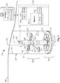
- FIG. 3 is a block diagram of an apparatus 200 and system 364 according to various embodiments of the invention.
- the apparatus 200 is illustrated using two different implementations of roller sets.
- the first implementation uses three arms 204 that attach to the housing 202, with sets of rollers that make up three corresponding omnidirectional wheels 80". Two of the arms 204' are attached to the housing 202 as shown in FIG. 2 , rotating about an attachment point to the housing 202 at an angle 206, and one of the arms 204" extends and retracts linearly (e.g., in a horizontal plane that is substantially orthogonal to the selected axis 212) between the housing 202 and the surface 222 of the borehole 220. Of course, different combinations of the arms 204 may be used, with either angular extension or linear extension, or some combinations of these, as shown. In addition, the arms 204' that move at an angle 206 can also be constructed to extend and retract in some embodiments. Sensors S are used to provide feedback to align the tool longitudinal axis with the selected axis 212 within the borehole 220, as described previously.
- a single wheel 80' is used to surround the housing 202.
- Compliantly-mounted rollers 82 are attached to the wheel 80'.
- Combinations of the first and second implementation may be used to align the tool longitudinal axis with the selected axis 212, as shown here. In some embodiments, only one of the first or the second implementation is used.
- a system 364 comprises one or more of the apparatus 200, including one or more housings 202.
- the housings 202 might take the form of a wireline tool body, or a down hole tool.
- the system 364 may comprise one or more processors 330, which may accompany the apparatus 200 down hole.
- the processors 330 may be attached to the housing 202, and used to control the motion of the apparatus 200, perhaps accessing a memory 350 containing a program PROG that has instructions to process the feedback received from the sensors S, and to actuate a drive mechanism 208 coupled to the extensible arms 204', 204".
- the processors 330 are located remotely from the apparatus 200.
- a data transceiver may be used to transmit acquired data values and/or processing results to the surface 366, and to receive commands (e.g., motion control commands for the apparatus 200) from processors 330 on the surface 366.
- the system 364 may comprise the data transceiver 344 (e.g., a telemetry transceiver) to transmit/receive data and command values to/from a surface workstation 356.
- the apparatus 200 comprises a housing 202 and rollers 82 that provide two rotational degrees of freedom.
- Some embodiments of the apparatus 200 may comprise a down hole housing 202 and at least one set of rollers 82 attached to the housing 202.
- the rollers 82 have two rotational degrees of freedom, to enable the housing 202 to move simultaneously along and about a longitudinal axis 212 within a borehole 220 in which the housing 202 is disposed, when the at least one set of rollers 82 contacts a surface 222 of the borehole 220.
- the rollers 82 can share two axes 84, 86 of rotation.
- the set(s) of rollers 82 e.g., a set of rollers 82 contained in an omnidirectional wheel
- the set(s) of rollers 82 can be attached to extensible arms 204.
- the apparatus 200 comprises at least one extensible arm 204 attached at a first end 230 to the housing 202, and at a second end 232 to the at least one set of rollers 82.
- An apparatus 200 may comprise multiple sets of rollers 82, perhaps used to provide a more stable platform for selecting an alignment axis 212 to be maintained as the housing 202 moves within the borehole 220.
- an apparatus 200 may comprise three sets of rollers, to provide a triangular vibration management platform.
- the extensible arm(s) 204 can move in a plane.
- the extensible arm 204 may comprise a laterally extensible arm 204' that is hingedly attached to the housing at a first end 230 to move within a plane intersecting the center of rotation (e.g., the axis 212), and that is rotationally attached to a center of rotation of the at least one set of rollers (e.g., at or along the secondary axis 86 of rotation) at the second end 232.
- the extensible arm(s) 204 can be constrained to move along a linear axis.
- the extensible arm 204 may comprise a laterally extensible arm 204" that is configured to move along a single linear axis.
- the set(s) of rollers 82 may have individual rollers 82 mounted so as to rotate about a circular axis (e.g., the primary axis of rotation 84).
- a circular axis e.g., the primary axis of rotation 84
- one or more of the sets of rollers 82 in the apparatus 200 may comprise individual rollers 82 mounted to rotate about a substantially circular axis 84 forming a plane substantially perpendicular to the longitudinal axis of the housing 202.
- the set(s) of rollers 82 may be located on a circle that does not include any part of the housing 202 (e.g., the wheels 80 shown in FIG. 2 ).
- the apparatus 200 may be constructed so that the housing 202 is not disposed within the substantially circular axis formed by the primary axis of rotation 84 with respect to individual sets of the rollers 82.
- One or more sets of rollers 82 may surround the housing 202, being attached to the housing 202 with an azimuthal bearing 88.
- the housing 202 is disposed within a substantially circular axis (e.g., the axis 84 of wheel 80') about which all individual rollers 82 in at least one set of rollers 82 can rotate.
- the set(s) of rollers 82 may be mounted to a compliant mounting system, perhaps comprising a series of springs or hydraulic shock absorbers.
- the apparatus 200 may comprise a compliant mounting system (e.g., including multiple compliant spokes 100 or axles 106) to permit the set(s) of rollers 82 to move toward a common center of rotation (e.g., the secondary axis 86) when uneven surfaces in the borehole 220 are encountered as the housing 202 moves along the selected longitudinal axis 212 within the borehole 220.
- a system 364 comprises a housing 202, rollers 82, and a feed-back controlled extension mechanism 324.
- a system 364 may comprise a down hole housing 202, at least one set of rollers 82 attached to the housing 202 (with two rotational degrees of freedom), as described previously.
- the rollers 82 enable the housing 202 to move simultaneously along and about a longitudinal axis 212 within a borehole 220 in which the housing 202 is disposed, as the set(s) of rollers 82 contact a surface 222 of the borehole 220.
- the system 364 may further comprise an extension mechanism 324 controlled by feedback to selectably move a centerline of the housing 212 with respect to the longitudinal axis 250 within the borehole 220.
- the extension mechanism 324 may comprise a drive mechanism 208, and one or more extensible arms 204.
- the extension mechanism 324 comprises a drive mechanism 208 (e.g., to extend the arms 204 out and away from the housing 202, as shown in FIGs. 2 and 3 ), and at least one extensible arm 204 coupled to the drive mechanism 208 and the at least one set of rollers 82.
- a geosteering controller can be used to operate the extension mechanism 324 remotely.
- the system 364 may comprise a remote geosteering controller GC, perhaps housed in the workstation 356, to operate the extension mechanism 324.
- a program PROG may be stored in the memory 350, which is accessed by the processors 330.
- Logic 340 may be used as an interface between the drive mechanism 208 of the apparatus 200 and the processors 330 and/or the geosteering controller GC. This arrangement can be used to control the apparatus 200, acquire measurement data, and generate signals to operate the drive mechanism 208.
- sensors S can be used to provide the feedback that operates the extension mechanism 324.
- the feedback may be provided by sensors S comprising at least one of ultrasonic sensors, accelerometers, strain gauges, calipers, or optical sensors. Other sensors types may be used.
- the housing centerline axis 12 may be substantially perpendicular to the axis of extension on the arms 204, as when the arms 204 comprise linearly extensible arms 204".
- the centerline of the housing 212 is substantially perpendicular to an axis of extension (along the length of the arm 204") associated with the extension mechanism 324.
- the housing 202 may comprise a variety of down hole devices.
- the housing 202 may comprise a wireline tool body, an MWD down hole tool, or an LWD down hole tool.
- Brakes B may be used to selectably reduce or halt the movement of individual rollers 82, or all of the rollers in a set. Therefore, the apparatus 200 (and therefore the system 364) may comprise a braking mechanism to slow or stop the movement of individual rollers 82, making up one or more sets of rollers 82.
- a clutch C may be used to provide rotating attachment, or fixed attachment, of the extension mechanism 324 to the housing 202.
- a clutch C may be used to selectably couple the extension mechanism 324 to the housing 202 via rotating or fixed attachment. Still further embodiments may be realized.
- FIG. 4 illustrates a wireline system 464 embodiment of the invention
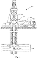
- FIG. 5 illustrates a drilling rig system 564 embodiment of the invention
- the systems 464, 564 may comprise portions of a wireline logging tool body 470 as part of a wireline logging operation, or of a down hole tool 524 as part of a down hole drilling operation.
- a drilling platform 486 is equipped with a derrick 488 that supports a hoist 490.
- Drilling oil and gas wells is commonly carried out using a string of drill pipes connected together so as to form a drilling string that is lowered through a rotary table 410 into a wellbore or borehole 412.
- a wireline logging tool body 470 such as a probe or sonde
- the wireline logging tool body 470 is lowered to the bottom of the region of interest and subsequently pulled upward at a substantially constant speed.
- the instruments included in the tool body 470 may be used to perform measurements on the subsurface geological formations 414 adjacent the borehole 412 (and the tool body 470).
- the measurement data can be communicated to a surface logging facility 492 for storage, processing, and analysis.
- the logging facility 492 may be provided with electronic equipment for various types of signal processing, which may be implemented by any one or more of the components of the apparatus 200 or system 346 in FIGs. 1-3 .
- Similar formation evaluation data may be gathered and analyzed during drilling operations (e.g., LWD operations, and by extension, sampling while drilling).
- the tool body 470 forms part of an apparatus 200 comprising an omnidirectional wheel 80", as shown in FIGs. 1B and 3 .
- the tool body 470 comprises an acoustic tool for generating acoustic noise, and obtaining/analyzing acoustic noise measurements from a subterranean formation through a borehole.
- the tool body 470 comprises an NMR tool.
- the tool is suspended in the wellbore by a wireline cable (e.g., wireline cable 474) that connects the tool to a surface control unit (e.g., comprising a workstation 454).
- the tool may be deployed in the borehole 412 on coiled tubing, jointed drill pipe, hard wired drill pipe, or any other suitable deployment technique.
- a system 564 may also form a portion of a drilling rig 502 located at the surface 504 of a well 506.
- the drilling rig 502 may provide support for a drill string 508.
- the drill string 508 may operate to penetrate the rotary table 410 for drilling the borehole 412 through the subsurface formations 414.
- the drill string 508 may include a Kelly 516, drill pipe 518, and a bottom hole assembly 520, perhaps located at the lower portion of the drill pipe 518.
- the bottom hole assembly 520 may include drill collars 522, a down hole tool 524, and a drill bit 526.
- the drill bit 526 may operate to create the borehole 412 by penetrating the surface 504 and the subsurface formations 414.
- the down hole tool 524 may comprise any of a number of different types of tools including MWD tools, LWD tools, and others.
- the drill string 508 (perhaps including the Kelly 516, the drill pipe 518, and the bottom hole assembly 520) may be rotated by the rotary table 410.
- the bottom hole assembly 520 may also be rotated by a motor (e.g., a mud motor) that is located down hole.
- the drill collars 522 may be used to add weight to the drill bit 526.
- the drill collars 522 may also operate to stiffen the bottom hole assembly 520, allowing the bottom hole assembly 520 to transfer the added weight to the drill bit 526, and in turn, to assist the drill bit 526 in penetrating the surface 504 and subsurface formations 414.
- a mud pump 532 may pump drilling fluid (sometimes known by those of ordinary skill in the art as "drilling) mud") from a mud pit 534 through a hose 536 into the drill pipe 518 and down to the drill bit 526.
- the drilling fluid can flow out from the drill bit 526 and be returned to the surface 504 through an annular area 540 between the drill pipe 518 and the sides of the borehole 412.
- the drilling fluid may then be returned to the mud pit 534, where such fluid is filtered.
- the drilling fluid can be used to cool the drill bit 526, as well as to provide lubrication for the drill bit 526 during drilling operations. Additionally, the drilling fluid may be used to remove subsurface formation cuttings created by operating the drill bit 526.
- systems 364, 464, 564 may include a drill collar 522, a down hole tool 524, and/or a wireline logging tool body 470 attached to one or more apparatus 200 similar to or identical to the apparatus 200 described above and illustrated in FIGs. 1-3 .
- Components of the system 364 in FIG. 3 may also be attached to the tool body 470 or the tool 524.
- the tool 524 forms part of an apparatus 200 comprising an omnidirectional wheel 80", as shown in FIGs. 1B and 3 , as well as to an apparatus 200 comprising multiple ones of the omnidirectional wheel 80', as shown in FIGs. 1A and 3 .
- the term “hosing” may include any one or more of a drill collar 522, a down hole tool 524, or a wireline logging tool body 470 (all having an outer wall, to enclose or attach to instrumentation, acoustic sources, sensors, fluid sampling devices, pressure measurement devices, transmitters, receivers, acquisition and processing logic, and data acquisition systems).
- the tool 524 may comprise a down hole tool, such as an LWD tool or MWD tool.
- the wireline tool body 470 may comprise a wireline logging tool, including a probe or sonde, for example, coupled to a logging cable 474.
- a system 464, 564 may include a display 496 to present feedback information from the apparatus 200, both measured and processed/calculated, perhaps in graphic form.
- a system 464, 564 may also include computation logic, perhaps as part of a surface logging facility 492, or a computer workstation 454, to receive signals from transmitters and receivers, and other instrumentation, to determine properties of the formation 414.
- a system 364, 464, 564 may comprise a tubular housing 202, such as a down hole tool body, including a wireline logging tool body 470 or a down hole tool 524 (e.g., an LWD or MWD tool body), and one or more apparatus 200 attached to the tubular housing 202, the apparatus 200 to be constructed and operated as described previously.
- a tubular housing 202 such as a down hole tool body, including a wireline logging tool body 470 or a down hole tool 524 (e.g., an LWD or MWD tool body), and one or more apparatus 200 attached to the tubular housing 202, the apparatus 200 to be constructed and operated as described previously.
- the wheels 80; rollers 82; bearings 88; spokes 100; axles 106; frame 108; apparatus 200; housing 202; extensible arms 204; drive mechanism 208; boreholes 220, 412; borehole surfaces 222; drill bit 226, 526; extension mechanism 324; processors 330; transceiver 344; systems 364, 464, 564; workstations 356, 454; surface 366; rotary table 410; wireline logging tool body 470; logging cable 474; drilling platform 486; derrick 488; hoist 490; logging facility 492; display 496; drill string 508; Kelly 516; drill pipe 518; bottom hole assembly 520; drill collars 522; down hole tool 524; mud pump 532; mud pit 534; hose 536; brakes B; clutch C; geosteering controller GC; and sensors S may all be characterized as "modules" herein.
- Such modules may include hardware circuitry, and/or a processor and/or memory circuits, software program modules and objects, and/or firmware, and combinations thereof, as desired by the architect of the apparatus 200 and systems 364, 464, 564 and as appropriate for particular implementations of various embodiments.
- such modules may be included in an apparatus and/or system operation simulation package, such as a software electrical signal simulation package, a power usage and distribution simulation package, a power/heat dissipation simulation package, and / or a combination of software and hardware used to simulate the operation of various potential embodiments.
- apparatus and systems of various embodiments can be used in applications other than for drilling operations, and thus, various embodiments are not to be so limited.
- the illustrations of apparatus 200 and systems 364, 464, 564 are intended to provide a general understanding of the structure of various embodiments, and they are not intended to serve as a complete description of all the elements and features of apparatus and systems that might make use of the structures described herein.
- Applications that may include the novel apparatus and systems of various embodiments include electronic circuitry used in high-speed computers, communication and signal processing circuitry, modems, processor modules, embedded processors, data switches, and application-specific modules. Such apparatus and systems may further be included as sub-components within a variety of electronic systems, such as televisions, cellular telephones, personal computers, workstations, radios, video players, vehicles, signal processing for geothermal tools and smart transducer interface node telemetry systems, among others. Some embodiments include a number of methods.
- FIG. 6 is a flow chart illustrating several methods 611 according to various embodiments of the invention.
- a method 611 may begin at block 621 with selecting a longitudinal axis within a borehole.
- the method 611 may continue on to block 625 with moving a down hole housing using at least one set of rollers attached to the housing to contact a surface of the borehole, so that simultaneous movement with two rotational degrees of freedom is enabled within the borehole as the centerline of the housing is substantially aligned with the selected longitudinal axis within the borehole while the housing moves along the selected longitudinal axis.
- Moving the housing can involve shared movement of the rollers about two axes.
- the activity at block 625 may comprise moving substantially all of the rollers (separately or together) about a shared, substantially circular axis of rotation to enable the housing to move along the selected longitudinal axis.
- the activity at block 625 may also comprise moving substantially all of the rollers together along the substantially circular axis of rotation.
- Moving the housing can involve receiving feedback to control the position of one or more arms attached to the housing.
- the method 611 may continue on to block 627 to include receiving electrical feedback with respect to the moving.
- the feedback can represent vibration or location information that is associated with the housing.
- the electrical feedback may represent vibration measurement and/or location measurement.
- the method 611 may operate to determine whether the housing that forms part of the various apparatus described herein is at the desired location (e.g., whether the centerline of the housing is substantially aligned, to within some desired distance, to the selected longitudinal axis in the borehole), or not. If so, then the method 611 may continue on to block 641, to include acquiring desired measurements, and conducting other activities using instrumentation and apparatus attached to the down hole housing.
- the method 611 may continue on to block 637 to include adjusting the position of at least one arm (e.g., an extensible arm) attached to the center of rotation (e.g., the axis 86 in FIGs 1A and 1B ) of one or more sets of rollers to move the centerline toward the selected longitudinal axis.
- at least one arm e.g., an extensible arm
- the center of rotation e.g., the axis 86 in FIGs 1A and 1B
- a software program can be launched from a computer-readable medium in a computer-based system to execute the functions defined in the software program.
- One of ordinary skill in the art will further understand the various programming languages that may be employed to create one or more software programs designed to implement and perform the methods disclosed herein.
- the programs may be structured in an object-orientated format using an abject-oriented language such as Java or C#.
- the programs can be structured in a procedure-orientated format using a procedural language, such as assembly or C.
- the software components may communicate using any of a number of mechanisms well known to those skilled in the art, such as application program interfaces or interprocess communication techniques, including remote procedure calls.
- the teachings of various embodiments are not limited to any particular programming language or environment. Thus, other embodiments may be realized.
- FIG. 7 is a block diagram of an article 700 of manufacture according to various embodiments, such as a computer, a memory system, a magnetic or optical disk, or some other storage device.
- the article 700 may include one or more processors 716 coupled to a machine-accessible medium such as a memory 736 (e.g., removable storage media, as well as any tangible, non-transitory memory including an electrical, optical, or electromagnetic conductor) having associated information 738 (e.g., computer program instructions and/or data), which when executed by one or more of the processors 716, results in a machine (e.g., the article 700) performing any of the actions described with respect to the methods of FIG. 6 , the apparatus of FIGs. 1-2 , and the systems of FIGs. 3-5 .
- the processors 716 may comprise one or more processors sold by Intel Corporation (e.g., Intel® CoreTM processor family), Advanced Micro Devices (e.g., AMD AthlonTM processors), and other semiconductor manufacturers.
- the article 700 may comprise one or more processors 716 coupled to a display 718 to display data processed by the processor 716 and/or a wireless transceiver 720 (e.g., a down hole telemetry transceiver) to receive and transmit data processed by the processor.
- a wireless transceiver 720 e.g., a down hole telemetry transceiver
- the memory system(s) included in the article 700 may include memory 736 comprising volatile memory (e.g., dynamic random access memory) and/or non-volatile memory.
- volatile memory e.g., dynamic random access memory
- non-volatile memory e.g., non-volatile memory.
- the memory 736 may be used to store data 740 processed by the processor 716.
- the article 700 may comprise communication apparatus 722, which may in turn include amplifiers 726 (e.g., preamplifiers or power amplifiers) and one or more antennas 724 (e.g., transmitting antennas and/or receiving antennas). Signals 742 received or transmitted by the communication apparatus 722, including feedback signals, may be processed according to the methods described herein.
- amplifiers 726 e.g., preamplifiers or power amplifiers
- antennas 724 e.g., transmitting antennas and/or receiving antennas.
- the article 700 may comprise a down hole tool, including the apparatus 200 shown in FIG. 2 .
- the article 700 is similar to or identical to the apparatus 200 or systems 346, 446, 546 shown in FIGs. 3-5 .
- using the apparatus, systems, and methods disclosed herein may operate to reduce vibration induced by drilling and other down hole activity, by smoothing and/or damping radial movements using active alignment of the housing axis, while providing a more substantial contact with the wall of the borehole.
- Reduced vibration has many benefits, including improved LWD tool reliability, and better measurement quality, significantly enhancing the value of services provided by an operation and exploration company.
- inventive subject matter may be referred to herein, individually and/or collectively, by the term "invention" merely for convenience and without intending to voluntarily limit the scope of this application to any single invention or inventive concept if more than one is in fact disclosed.
- inventive subject matter may be referred to herein, individually and/or collectively, by the term "invention" merely for convenience and without intending to voluntarily limit the scope of this application to any single invention or inventive concept if more than one is in fact disclosed.
- inventive subject matter merely for convenience and without intending to voluntarily limit the scope of this application to any single invention or inventive concept if more than one is in fact disclosed.
Claims (15)
- Vorrichtung (200), umfassend:ein Bohrlochgehäuse (202);mindestens drei ausfahrbare Arme (204), wobei jeder ausfahrbare Arm an einem ersten Ende (230) an dem Gehäuse angebracht ist,dadurch gekennzeichnet, dass jeder ausfahrbare Arm an einem zweiten Ende (232) an mindestens einem Satz Rollen (82) angebracht ist,wobei jeder Satz Rollen zwei Rotationsfreiheitsgrade aufweist, um es dem Gehäuse zu ermöglichen, sich gleichzeitig entlang und um eine Längsachse (250) innerhalb eines Bohrlochs (220) zu bewegen, in dem das Gehäuse angeordnet ist, wenn der Satz Rollen eine Oberfläche (222) des Bohrlochs berührt.
- Vorrichtung nach Anspruch 1, wobei der mindestens eine Satz Rollen eine Vielzahl von Einzelrollen umfasst, denen alle eine Primärdrehachse (84) und eine von der Primärdrehachse verschiedene Sekundärdrehachse (86) gemein sind.
- Vorrichtung nach Anspruch 1, wobei die ausfahrbaren Arme Folgendes umfassen:einen seitlich ausfahrbaren Arm (204'), der so konfiguriert ist, dass er sich entlang einer einzigen linearen Achse bewegt.
- Vorrichtung nach Anspruch 1, wobei die ausfahrbaren Arme Folgendes umfassen:einen seitlich ausfahrbaren Arm, der an dem ersten Ende an dem Gehäuse gelenkig angebracht ist, um sich innerhalb einer Ebene zu bewegen, die den Drehpunkt schneidet, und der an einem Drehpunkt des mindestens einen Satzes Rollen an dem zweiten Ende drehbar angebracht ist.
- Vorrichtung nach Anspruch 1, wobei der mindestens eine Satz Rollen Folgendes umfasst:einzelne Rollen, montiert, um sich um eine im Wesentlichen kreisförmige Achse zu drehen, die eine Ebene bildet, die im Wesentlichen senkrecht zur Längsachse ist.
- Vorrichtung nach Anspruch 5, wobei das Gehäuse nicht innerhalb der im Wesentlichen kreisförmigen Achse angeordnet ist.
- Vorrichtung nach Anspruch 1, ferner umfassend:ein nachgiebiges Montagesystem, das es dem mindestens einen Satz Rollen ermöglicht, sich in Richtung eines gemeinsamen Drehpunkts zu bewegen, wenn unebene Oberflächen in dem Bohrloch angetroffen werden, wenn sich das Gehäuse entlang der Längsachse bewegt.
- System (364), umfassend:eine Vorrichtung (200) nach Anspruch 1; undeinen durch Rückkopplung gesteuerten Ausfahrmechanismus (324), um eine Mittellinie des Gehäuses in Bezug auf die Längsachse innerhalb des Bohrlochs wählbar zu bewegen.
- System nach Anspruch 8, wobei der Ausfahrmechanismus Folgendes umfasst:einen Antriebsmechanismus (208); unddie mindestens drei ausfahrbaren Arme, wobei die Arme mit dem Antriebsmechanismus gekoppelt sind.
- Verfahren nach Anspruch 8, umfassend:eine ferngesteuerte Geosteering-Steuerung, um den Ausfahrmechanismus zu betreiben.
- System nach Anspruch 8, wobei:a) das Gehäuse innerhalb einer im Wesentlichen kreisförmigen Achse angeordnet ist, um die sich alle einzelnen Rollen in dem mindestens einen Satz Rollen drehen können;b) die Rückkopplung durch Sensoren erfolgt, die mindestens einen von Ultraschallsensoren, Beschleunigungsmessern, Dehnungsmessstreifen oder optischen Sensoren umfassen; oderc) die Mittellinie des Gehäuses im Wesentlichen senkrecht zu einer mit dem Ausfahrmechanismus assoziierten Ausfahrachse ist.
- System nach Anspruch 8, wobei das Gehäuse Folgendes umfasst:eins von einem Wireline-Werkzeugkörper, einem Bohrlochwerkzeug für Messungen während des Bohrens oder einem Bohrlochwerkzeug für Vermessungen während des Bohrens.
- System nach Anspruch 10, ferner umfassend:a) einen Bremsmechanismus zum Verlangsamen oder Stoppen der Bewegung einzelner Rollen in dem mindestens einen Satz Rollen; oderb) einen Kupplungsmechanismus, um den Ausfahrmechanismus über eine drehbare oder feste Anbringung wählbar mit dem Gehäuse zu koppeln.
- Verfahren, umfassend,
Auswählen einer Längsachse innerhalb eines Bohrlochs; und
Bewegen eines Bohrlochgehäuses (202) unter Verwendung von mindestens drei ausfahrbaren Armen (204), die an einem ersten Ende (230) an dem Gehäuse angebracht sind,
dadurch gekennzeichnet, dass jeder ausfahrbare Arm an einem zweiten Ende (232) an mindestens einem Satz Rollen (82) angebracht ist, wobei jeder Satz Rollen an dem Gehäuse angebracht ist, um eine Oberfläche (222) des Bohrlochs zu berühren, so dass eine gleichzeitige Bewegung mit zwei Rotationsfreiheitsgraden innerhalb des Bohrlochs ermöglicht wird, wenn eine Mittellinie des Gehäuses im Wesentlichen mit der ausgewählten Längsachse ausgerichtet ist, während sich das Gehäuse entlang der ausgewählten Längsachse bewegt. - Verfahren nach Anspruch 14, wobei das Bewegen Folgendes umfasst:a) Bewegen im Wesentlichen aller Rollen um eine gemeinsame, im Wesentlichen kreisförmige Drehachse, um es dem Gehäuse zu ermöglichen, sich entlang der ausgewählten Längsachse zu bewegen; und
Bewegen im Wesentlichen aller Rollen entlang der im Wesentlichen kreisförmigen Drehachse; oderb) Empfangen einer elektrischen Rückkopplung bezüglich der Bewegung; und
Einstellen einer Position von mindestens einem Arm, der an einem Drehpunkt für den mindestens einen Satz Rollen angebracht ist, um die Mittellinie in Richtung der ausgewählten Längsachse zu bewegen, wobei vorzugsweise die elektrische Rückkopplung eine von einer Schwingungsmessung oder einer Ortsmessung darstellt.
Applications Claiming Priority (1)
| Application Number | Priority Date | Filing Date | Title |
|---|---|---|---|
| PCT/US2012/048310 WO2014018040A1 (en) | 2012-07-26 | 2012-07-26 | Axis maintenance apparatus, systems, and methods |
Publications (2)
| Publication Number | Publication Date |
|---|---|
| EP2885484A1 EP2885484A1 (de) | 2015-06-24 |
| EP2885484B1 true EP2885484B1 (de) | 2017-09-27 |
Family
ID=46640767
Family Applications (1)
| Application Number | Title | Priority Date | Filing Date |
|---|---|---|---|
| EP12745737.2A Not-in-force EP2885484B1 (de) | 2012-07-26 | 2012-07-26 | Achsenwartungsvorrichtung, systeme und verfahren |
Country Status (6)
| Country | Link |
|---|---|
| US (1) | US9869141B2 (de) |
| EP (1) | EP2885484B1 (de) |
| AU (1) | AU2012386004B2 (de) |
| CA (1) | CA2879612C (de) |
| NO (1) | NO2885484T3 (de) |
| WO (1) | WO2014018040A1 (de) |
Families Citing this family (6)
| Publication number | Priority date | Publication date | Assignee | Title |
|---|---|---|---|---|
| EP3025022A1 (de) * | 2013-10-03 | 2016-06-01 | Halliburton Energy Services, Inc. | Rohr und bohrlochbilderzeugungswerkzeug mit mehrteiligen anpassbaren sensoren |
| GB2534896A (en) * | 2015-02-04 | 2016-08-10 | Nov Downhole Eurasia Ltd | Rotary downhole tool |
| DE102017209356A1 (de) * | 2017-06-01 | 2018-12-06 | Trumpf Medizin Systeme Gmbh + Co. Kg | Laufrad |
| WO2020122856A1 (en) * | 2018-12-10 | 2020-06-18 | Halliburton Energy Services, Inc. | Flow characterization tool |
| US10947794B2 (en) * | 2019-03-01 | 2021-03-16 | Saudi Arabian Oil Company | Method and system for extended reach coiled tubing |
| US11236563B1 (en) | 2020-07-30 | 2022-02-01 | Saudi Arabian Oil Company | Autonomous downhole tool |
Family Cites Families (11)
| Publication number | Priority date | Publication date | Assignee | Title |
|---|---|---|---|---|
| FR2168920B1 (de) | 1972-01-26 | 1975-06-13 | Schlumberger Prospection | |
| US4192380A (en) | 1978-10-02 | 1980-03-11 | Dresser Industries, Inc. | Method and apparatus for logging inclined earth boreholes |
| US4303270A (en) * | 1979-09-11 | 1981-12-01 | Walker-Neer Manufacturing Co., Inc. | Self-centering clamp |
| GB8806109D0 (en) * | 1988-03-15 | 1988-04-13 | Anderson C A | Downhole stabilisers |
| US5358042A (en) * | 1993-04-07 | 1994-10-25 | Marathon Oil Company | High angle and horizontal wellbore centralizer and method of use |
| US6739409B2 (en) | 1999-02-09 | 2004-05-25 | Baker Hughes Incorporated | Method and apparatus for a downhole NMR MWD tool configuration |
| US6250394B1 (en) | 1999-09-23 | 2001-06-26 | Benny Donald Mashburn | Apparatus for assisting the advancement of a work string and method |
| US6257356B1 (en) | 1999-10-06 | 2001-07-10 | Aps Technology, Inc. | Magnetorheological fluid apparatus, especially adapted for use in a steerable drill string, and a method of using same |
| GB0015020D0 (en) | 2000-06-20 | 2000-08-09 | Downhole Products Plc | Centraliser |
| GB2424018B (en) | 2003-11-07 | 2008-05-28 | Aps Technology Inc | System and method for damping vibration in a drill string |
| US20100276138A1 (en) | 2009-05-01 | 2010-11-04 | Flotek Industries, Inc. | Low Friction Centralizer |
-
2012
- 2012-07-26 US US14/414,609 patent/US9869141B2/en not_active Expired - Fee Related
- 2012-07-26 EP EP12745737.2A patent/EP2885484B1/de not_active Not-in-force
- 2012-07-26 NO NO12745737A patent/NO2885484T3/no unknown
- 2012-07-26 AU AU2012386004A patent/AU2012386004B2/en not_active Ceased
- 2012-07-26 WO PCT/US2012/048310 patent/WO2014018040A1/en active Application Filing
- 2012-07-26 CA CA2879612A patent/CA2879612C/en not_active Expired - Fee Related
Non-Patent Citations (1)
| Title |
|---|
| None * |
Also Published As
| Publication number | Publication date |
|---|---|
| CA2879612C (en) | 2017-03-14 |
| NO2885484T3 (de) | 2018-02-24 |
| CA2879612A1 (en) | 2014-01-30 |
| AU2012386004B2 (en) | 2016-11-03 |
| AU2012386004A1 (en) | 2015-03-12 |
| US20150167402A1 (en) | 2015-06-18 |
| WO2014018040A1 (en) | 2014-01-30 |
| US9869141B2 (en) | 2018-01-16 |
| EP2885484A1 (de) | 2015-06-24 |
Similar Documents
| Publication | Publication Date | Title |
|---|---|---|
| EP2885484B1 (de) | Achsenwartungsvorrichtung, systeme und verfahren | |
| CA2322884C (en) | A non-rotating sensor assembly for measurement-while-drilling | |
| CA2661911C (en) | Apparatus and methods for estimating loads and movements of members downhole | |
| AU2014398251B2 (en) | Reluctance sensor for measuring a magnetizable structure in a subterranean environment | |
| CN109844261A (zh) | 使用自调节偏转装置和偏转传感器钻探定向井的钻探设备 | |
| US10408963B2 (en) | Measurement calibration apparatus, methods, and systems | |
| US10871033B2 (en) | Steering assembly position sensing using radio frequency identification | |
| WO2014105519A1 (en) | Apparatus and method for drilling deviated wellbores that utilizes an internally tilted drive shaft in a drilling assembly | |
| US20230243220A1 (en) | Adaptive Control of Rotating or Non-Rotating Transducer and Sensors Casing Stand-Off Supported by Casing Centralizers | |
| US9605527B2 (en) | Reducing rotational vibration in rotational measurements | |
| US20210131265A1 (en) | Measurement of Torque with Shear Stress Sensors | |
| US20170328143A1 (en) | Blade-mounted sensor apparatus, systems, and methods | |
| US9158014B2 (en) | Acoustic source apparatus, systems, and methods | |
| US11536130B2 (en) | Logging while drilling (LWD) mechanical calipers | |
| US20160215611A1 (en) | Method and apparatus for orienting a downhole tool | |
| Cayeux | Reconstruction of Pipe Displacement Based on High-Frequency Triaxial Accelerometer Measurements | |
| WO2021062486A1 (en) | Improvements in or relating to assessment of mining deposits |
Legal Events
| Date | Code | Title | Description |
|---|---|---|---|
| PUAI | Public reference made under article 153(3) epc to a published international application that has entered the european phase |
Free format text: ORIGINAL CODE: 0009012 |
|
| 17P | Request for examination filed |
Effective date: 20150212 |
|
| AK | Designated contracting states |
Kind code of ref document: A1 Designated state(s): AL AT BE BG CH CY CZ DE DK EE ES FI FR GB GR HR HU IE IS IT LI LT LU LV MC MK MT NL NO PL PT RO RS SE SI SK SM TR |
|
| AX | Request for extension of the european patent |
Extension state: BA ME |
|
| DAX | Request for extension of the european patent (deleted) | ||
| STAA | Information on the status of an ep patent application or granted ep patent |
Free format text: STATUS: EXAMINATION IS IN PROGRESS |
|
| 17Q | First examination report despatched |
Effective date: 20170123 |
|
| GRAP | Despatch of communication of intention to grant a patent |
Free format text: ORIGINAL CODE: EPIDOSNIGR1 |
|
| STAA | Information on the status of an ep patent application or granted ep patent |
Free format text: STATUS: GRANT OF PATENT IS INTENDED |
|
| INTG | Intention to grant announced |
Effective date: 20170613 |
|
| GRAS | Grant fee paid |
Free format text: ORIGINAL CODE: EPIDOSNIGR3 |
|
| GRAA | (expected) grant |
Free format text: ORIGINAL CODE: 0009210 |
|
| STAA | Information on the status of an ep patent application or granted ep patent |
Free format text: STATUS: THE PATENT HAS BEEN GRANTED |
|
| AK | Designated contracting states |
Kind code of ref document: B1 Designated state(s): AL AT BE BG CH CY CZ DE DK EE ES FI FR GB GR HR HU IE IS IT LI LT LU LV MC MK MT NL NO PL PT RO RS SE SI SK SM TR |
|
| REG | Reference to a national code |
Ref country code: GB Ref legal event code: FG4D |
|
| REG | Reference to a national code |
Ref country code: CH Ref legal event code: EP |
|
| REG | Reference to a national code |
Ref country code: AT Ref legal event code: REF Ref document number: 932147 Country of ref document: AT Kind code of ref document: T Effective date: 20171015 |
|
| REG | Reference to a national code |
Ref country code: IE Ref legal event code: FG4D |
|
| REG | Reference to a national code |
Ref country code: DE Ref legal event code: R096 Ref document number: 602012037817 Country of ref document: DE |
|
| REG | Reference to a national code |
Ref country code: NO Ref legal event code: T2 Effective date: 20170927 |
|
| PG25 | Lapsed in a contracting state [announced via postgrant information from national office to epo] |
Ref country code: FI Free format text: LAPSE BECAUSE OF FAILURE TO SUBMIT A TRANSLATION OF THE DESCRIPTION OR TO PAY THE FEE WITHIN THE PRESCRIBED TIME-LIMIT Effective date: 20170927 Ref country code: HR Free format text: LAPSE BECAUSE OF FAILURE TO SUBMIT A TRANSLATION OF THE DESCRIPTION OR TO PAY THE FEE WITHIN THE PRESCRIBED TIME-LIMIT Effective date: 20170927 Ref country code: LT Free format text: LAPSE BECAUSE OF FAILURE TO SUBMIT A TRANSLATION OF THE DESCRIPTION OR TO PAY THE FEE WITHIN THE PRESCRIBED TIME-LIMIT Effective date: 20170927 Ref country code: SE Free format text: LAPSE BECAUSE OF FAILURE TO SUBMIT A TRANSLATION OF THE DESCRIPTION OR TO PAY THE FEE WITHIN THE PRESCRIBED TIME-LIMIT Effective date: 20170927 |
|
| REG | Reference to a national code |
Ref country code: NL Ref legal event code: MP Effective date: 20170927 |
|
| REG | Reference to a national code |
Ref country code: LT Ref legal event code: MG4D |
|
| REG | Reference to a national code |
Ref country code: AT Ref legal event code: MK05 Ref document number: 932147 Country of ref document: AT Kind code of ref document: T Effective date: 20170927 |
|
| PG25 | Lapsed in a contracting state [announced via postgrant information from national office to epo] |
Ref country code: RS Free format text: LAPSE BECAUSE OF FAILURE TO SUBMIT A TRANSLATION OF THE DESCRIPTION OR TO PAY THE FEE WITHIN THE PRESCRIBED TIME-LIMIT Effective date: 20170927 Ref country code: BG Free format text: LAPSE BECAUSE OF FAILURE TO SUBMIT A TRANSLATION OF THE DESCRIPTION OR TO PAY THE FEE WITHIN THE PRESCRIBED TIME-LIMIT Effective date: 20171227 Ref country code: LV Free format text: LAPSE BECAUSE OF FAILURE TO SUBMIT A TRANSLATION OF THE DESCRIPTION OR TO PAY THE FEE WITHIN THE PRESCRIBED TIME-LIMIT Effective date: 20170927 Ref country code: GR Free format text: LAPSE BECAUSE OF FAILURE TO SUBMIT A TRANSLATION OF THE DESCRIPTION OR TO PAY THE FEE WITHIN THE PRESCRIBED TIME-LIMIT Effective date: 20171228 |
|
| PG25 | Lapsed in a contracting state [announced via postgrant information from national office to epo] |
Ref country code: NL Free format text: LAPSE BECAUSE OF FAILURE TO SUBMIT A TRANSLATION OF THE DESCRIPTION OR TO PAY THE FEE WITHIN THE PRESCRIBED TIME-LIMIT Effective date: 20170927 |
|
| PG25 | Lapsed in a contracting state [announced via postgrant information from national office to epo] |
Ref country code: RO Free format text: LAPSE BECAUSE OF FAILURE TO SUBMIT A TRANSLATION OF THE DESCRIPTION OR TO PAY THE FEE WITHIN THE PRESCRIBED TIME-LIMIT Effective date: 20170927 Ref country code: ES Free format text: LAPSE BECAUSE OF FAILURE TO SUBMIT A TRANSLATION OF THE DESCRIPTION OR TO PAY THE FEE WITHIN THE PRESCRIBED TIME-LIMIT Effective date: 20170927 Ref country code: CZ Free format text: LAPSE BECAUSE OF FAILURE TO SUBMIT A TRANSLATION OF THE DESCRIPTION OR TO PAY THE FEE WITHIN THE PRESCRIBED TIME-LIMIT Effective date: 20170927 |
|
| PG25 | Lapsed in a contracting state [announced via postgrant information from national office to epo] |
Ref country code: AT Free format text: LAPSE BECAUSE OF FAILURE TO SUBMIT A TRANSLATION OF THE DESCRIPTION OR TO PAY THE FEE WITHIN THE PRESCRIBED TIME-LIMIT Effective date: 20170927 Ref country code: SM Free format text: LAPSE BECAUSE OF FAILURE TO SUBMIT A TRANSLATION OF THE DESCRIPTION OR TO PAY THE FEE WITHIN THE PRESCRIBED TIME-LIMIT Effective date: 20170927 Ref country code: IS Free format text: LAPSE BECAUSE OF FAILURE TO SUBMIT A TRANSLATION OF THE DESCRIPTION OR TO PAY THE FEE WITHIN THE PRESCRIBED TIME-LIMIT Effective date: 20180127 Ref country code: SK Free format text: LAPSE BECAUSE OF FAILURE TO SUBMIT A TRANSLATION OF THE DESCRIPTION OR TO PAY THE FEE WITHIN THE PRESCRIBED TIME-LIMIT Effective date: 20170927 Ref country code: IT Free format text: LAPSE BECAUSE OF FAILURE TO SUBMIT A TRANSLATION OF THE DESCRIPTION OR TO PAY THE FEE WITHIN THE PRESCRIBED TIME-LIMIT Effective date: 20170927 Ref country code: EE Free format text: LAPSE BECAUSE OF FAILURE TO SUBMIT A TRANSLATION OF THE DESCRIPTION OR TO PAY THE FEE WITHIN THE PRESCRIBED TIME-LIMIT Effective date: 20170927 |
|
| REG | Reference to a national code |
Ref country code: DE Ref legal event code: R097 Ref document number: 602012037817 Country of ref document: DE |
|
| PG25 | Lapsed in a contracting state [announced via postgrant information from national office to epo] |
Ref country code: DK Free format text: LAPSE BECAUSE OF FAILURE TO SUBMIT A TRANSLATION OF THE DESCRIPTION OR TO PAY THE FEE WITHIN THE PRESCRIBED TIME-LIMIT Effective date: 20170927 |
|
| PLBE | No opposition filed within time limit |
Free format text: ORIGINAL CODE: 0009261 |
|
| STAA | Information on the status of an ep patent application or granted ep patent |
Free format text: STATUS: NO OPPOSITION FILED WITHIN TIME LIMIT |
|
| PG25 | Lapsed in a contracting state [announced via postgrant information from national office to epo] |
Ref country code: PL Free format text: LAPSE BECAUSE OF FAILURE TO SUBMIT A TRANSLATION OF THE DESCRIPTION OR TO PAY THE FEE WITHIN THE PRESCRIBED TIME-LIMIT Effective date: 20170927 |
|
| 26N | No opposition filed |
Effective date: 20180628 |
|
| PG25 | Lapsed in a contracting state [announced via postgrant information from national office to epo] |
Ref country code: SI Free format text: LAPSE BECAUSE OF FAILURE TO SUBMIT A TRANSLATION OF THE DESCRIPTION OR TO PAY THE FEE WITHIN THE PRESCRIBED TIME-LIMIT Effective date: 20170927 |
|
| REG | Reference to a national code |
Ref country code: CH Ref legal event code: PL |
|
| PG25 | Lapsed in a contracting state [announced via postgrant information from national office to epo] |
Ref country code: MC Free format text: LAPSE BECAUSE OF FAILURE TO SUBMIT A TRANSLATION OF THE DESCRIPTION OR TO PAY THE FEE WITHIN THE PRESCRIBED TIME-LIMIT Effective date: 20170927 Ref country code: LU Free format text: LAPSE BECAUSE OF NON-PAYMENT OF DUE FEES Effective date: 20180726 |
|
| REG | Reference to a national code |
Ref country code: BE Ref legal event code: MM Effective date: 20180731 |
|
| REG | Reference to a national code |
Ref country code: IE Ref legal event code: MM4A |
|
| PG25 | Lapsed in a contracting state [announced via postgrant information from national office to epo] |
Ref country code: IE Free format text: LAPSE BECAUSE OF NON-PAYMENT OF DUE FEES Effective date: 20180726 Ref country code: FR Free format text: LAPSE BECAUSE OF NON-PAYMENT OF DUE FEES Effective date: 20180731 Ref country code: LI Free format text: LAPSE BECAUSE OF NON-PAYMENT OF DUE FEES Effective date: 20180731 Ref country code: CH Free format text: LAPSE BECAUSE OF NON-PAYMENT OF DUE FEES Effective date: 20180731 |
|
| PG25 | Lapsed in a contracting state [announced via postgrant information from national office to epo] |
Ref country code: BE Free format text: LAPSE BECAUSE OF NON-PAYMENT OF DUE FEES Effective date: 20180731 |
|
| PGFP | Annual fee paid to national office [announced via postgrant information from national office to epo] |
Ref country code: NO Payment date: 20190625 Year of fee payment: 8 |
|
| PGFP | Annual fee paid to national office [announced via postgrant information from national office to epo] |
Ref country code: DE Payment date: 20190730 Year of fee payment: 8 Ref country code: GB Payment date: 20190610 Year of fee payment: 8 |
|
| PG25 | Lapsed in a contracting state [announced via postgrant information from national office to epo] |
Ref country code: MT Free format text: LAPSE BECAUSE OF NON-PAYMENT OF DUE FEES Effective date: 20180726 |
|
| PG25 | Lapsed in a contracting state [announced via postgrant information from national office to epo] |
Ref country code: TR Free format text: LAPSE BECAUSE OF FAILURE TO SUBMIT A TRANSLATION OF THE DESCRIPTION OR TO PAY THE FEE WITHIN THE PRESCRIBED TIME-LIMIT Effective date: 20170927 |
|
| PG25 | Lapsed in a contracting state [announced via postgrant information from national office to epo] |
Ref country code: PT Free format text: LAPSE BECAUSE OF FAILURE TO SUBMIT A TRANSLATION OF THE DESCRIPTION OR TO PAY THE FEE WITHIN THE PRESCRIBED TIME-LIMIT Effective date: 20170927 Ref country code: HU Free format text: LAPSE BECAUSE OF FAILURE TO SUBMIT A TRANSLATION OF THE DESCRIPTION OR TO PAY THE FEE WITHIN THE PRESCRIBED TIME-LIMIT; INVALID AB INITIO Effective date: 20120726 |
|
| PG25 | Lapsed in a contracting state [announced via postgrant information from national office to epo] |
Ref country code: MK Free format text: LAPSE BECAUSE OF NON-PAYMENT OF DUE FEES Effective date: 20170927 Ref country code: CY Free format text: LAPSE BECAUSE OF FAILURE TO SUBMIT A TRANSLATION OF THE DESCRIPTION OR TO PAY THE FEE WITHIN THE PRESCRIBED TIME-LIMIT Effective date: 20170927 |
|
| PG25 | Lapsed in a contracting state [announced via postgrant information from national office to epo] |
Ref country code: AL Free format text: LAPSE BECAUSE OF FAILURE TO SUBMIT A TRANSLATION OF THE DESCRIPTION OR TO PAY THE FEE WITHIN THE PRESCRIBED TIME-LIMIT Effective date: 20170927 |
|
| REG | Reference to a national code |
Ref country code: DE Ref legal event code: R119 Ref document number: 602012037817 Country of ref document: DE |
|
| REG | Reference to a national code |
Ref country code: NO Ref legal event code: MMEP |
|
| GBPC | Gb: european patent ceased through non-payment of renewal fee |
Effective date: 20200726 |
|
| PG25 | Lapsed in a contracting state [announced via postgrant information from national office to epo] |
Ref country code: NO Free format text: LAPSE BECAUSE OF NON-PAYMENT OF DUE FEES Effective date: 20200731 Ref country code: GB Free format text: LAPSE BECAUSE OF NON-PAYMENT OF DUE FEES Effective date: 20200726 |
|
| PG25 | Lapsed in a contracting state [announced via postgrant information from national office to epo] |
Ref country code: DE Free format text: LAPSE BECAUSE OF NON-PAYMENT OF DUE FEES Effective date: 20210202 |