EP2885123B1 - Metal cans with peelable lids - Google Patents
Metal cans with peelable lids Download PDFInfo
- Publication number
- EP2885123B1 EP2885123B1 EP13750097.1A EP13750097A EP2885123B1 EP 2885123 B1 EP2885123 B1 EP 2885123B1 EP 13750097 A EP13750097 A EP 13750097A EP 2885123 B1 EP2885123 B1 EP 2885123B1
- Authority
- EP
- European Patent Office
- Prior art keywords
- flange
- peelable lid
- punch
- metal
- peelable
- Prior art date
- Legal status (The legal status is an assumption and is not a legal conclusion. Google has not performed a legal analysis and makes no representation as to the accuracy of the status listed.)
- Not-in-force
Links
Images


Classifications
-
- B—PERFORMING OPERATIONS; TRANSPORTING
- B65—CONVEYING; PACKING; STORING; HANDLING THIN OR FILAMENTARY MATERIAL
- B65B—MACHINES, APPARATUS OR DEVICES FOR, OR METHODS OF, PACKAGING ARTICLES OR MATERIALS; UNPACKING
- B65B7/00—Closing containers or receptacles after filling
- B65B7/16—Closing semi-rigid or rigid containers or receptacles not deformed by, or not taking-up shape of, contents, e.g. boxes or cartons
- B65B7/28—Closing semi-rigid or rigid containers or receptacles not deformed by, or not taking-up shape of, contents, e.g. boxes or cartons by applying separate preformed closures, e.g. lids, covers
- B65B7/2842—Securing closures on containers
- B65B7/2878—Securing closures on containers by heat-sealing
-
- B—PERFORMING OPERATIONS; TRANSPORTING
- B65—CONVEYING; PACKING; STORING; HANDLING THIN OR FILAMENTARY MATERIAL
- B65D—CONTAINERS FOR STORAGE OR TRANSPORT OF ARTICLES OR MATERIALS, e.g. BAGS, BARRELS, BOTTLES, BOXES, CANS, CARTONS, CRATES, DRUMS, JARS, TANKS, HOPPERS, FORWARDING CONTAINERS; ACCESSORIES, CLOSURES, OR FITTINGS THEREFOR; PACKAGING ELEMENTS; PACKAGES
- B65D43/00—Lids or covers for rigid or semi-rigid containers
- B65D43/02—Removable lids or covers
- B65D43/0202—Removable lids or covers without integral tamper element
- B65D43/0233—Removable lids or covers without integral tamper element secured by rolling or other plastic deformation
-
- B—PERFORMING OPERATIONS; TRANSPORTING
- B32—LAYERED PRODUCTS
- B32B—LAYERED PRODUCTS, i.e. PRODUCTS BUILT-UP OF STRATA OF FLAT OR NON-FLAT, e.g. CELLULAR OR HONEYCOMB, FORM
- B32B37/00—Methods or apparatus for laminating, e.g. by curing or by ultrasonic bonding
- B32B37/14—Methods or apparatus for laminating, e.g. by curing or by ultrasonic bonding characterised by the properties of the layers
- B32B37/16—Methods or apparatus for laminating, e.g. by curing or by ultrasonic bonding characterised by the properties of the layers with all layers existing as coherent layers before laminating
- B32B37/18—Methods or apparatus for laminating, e.g. by curing or by ultrasonic bonding characterised by the properties of the layers with all layers existing as coherent layers before laminating involving the assembly of discrete sheets or panels only
-
- B—PERFORMING OPERATIONS; TRANSPORTING
- B32—LAYERED PRODUCTS
- B32B—LAYERED PRODUCTS, i.e. PRODUCTS BUILT-UP OF STRATA OF FLAT OR NON-FLAT, e.g. CELLULAR OR HONEYCOMB, FORM
- B32B38/00—Ancillary operations in connection with laminating processes
- B32B38/0012—Mechanical treatment, e.g. roughening, deforming, stretching
-
- B—PERFORMING OPERATIONS; TRANSPORTING
- B65—CONVEYING; PACKING; STORING; HANDLING THIN OR FILAMENTARY MATERIAL
- B65D—CONTAINERS FOR STORAGE OR TRANSPORT OF ARTICLES OR MATERIALS, e.g. BAGS, BARRELS, BOTTLES, BOXES, CANS, CARTONS, CRATES, DRUMS, JARS, TANKS, HOPPERS, FORWARDING CONTAINERS; ACCESSORIES, CLOSURES, OR FITTINGS THEREFOR; PACKAGING ELEMENTS; PACKAGES
- B65D1/00—Containers having bodies formed in one piece, e.g. by casting metallic material, by moulding plastics, by blowing vitreous material, by throwing ceramic material, by moulding pulped fibrous material, by deep-drawing operations performed on sheet material
- B65D1/12—Cans, casks, barrels, or drums
-
- B—PERFORMING OPERATIONS; TRANSPORTING
- B65—CONVEYING; PACKING; STORING; HANDLING THIN OR FILAMENTARY MATERIAL
- B65D—CONTAINERS FOR STORAGE OR TRANSPORT OF ARTICLES OR MATERIALS, e.g. BAGS, BARRELS, BOTTLES, BOXES, CANS, CARTONS, CRATES, DRUMS, JARS, TANKS, HOPPERS, FORWARDING CONTAINERS; ACCESSORIES, CLOSURES, OR FITTINGS THEREFOR; PACKAGING ELEMENTS; PACKAGES
- B65D1/00—Containers having bodies formed in one piece, e.g. by casting metallic material, by moulding plastics, by blowing vitreous material, by throwing ceramic material, by moulding pulped fibrous material, by deep-drawing operations performed on sheet material
- B65D1/40—Details of walls
-
- B—PERFORMING OPERATIONS; TRANSPORTING
- B29—WORKING OF PLASTICS; WORKING OF SUBSTANCES IN A PLASTIC STATE IN GENERAL
- B29C—SHAPING OR JOINING OF PLASTICS; SHAPING OF MATERIAL IN A PLASTIC STATE, NOT OTHERWISE PROVIDED FOR; AFTER-TREATMENT OF THE SHAPED PRODUCTS, e.g. REPAIRING
- B29C65/00—Joining or sealing of preformed parts, e.g. welding of plastics materials; Apparatus therefor
- B29C65/02—Joining or sealing of preformed parts, e.g. welding of plastics materials; Apparatus therefor by heating, with or without pressure
- B29C65/18—Joining or sealing of preformed parts, e.g. welding of plastics materials; Apparatus therefor by heating, with or without pressure using heated tools
-
- B—PERFORMING OPERATIONS; TRANSPORTING
- B29—WORKING OF PLASTICS; WORKING OF SUBSTANCES IN A PLASTIC STATE IN GENERAL
- B29C—SHAPING OR JOINING OF PLASTICS; SHAPING OF MATERIAL IN A PLASTIC STATE, NOT OTHERWISE PROVIDED FOR; AFTER-TREATMENT OF THE SHAPED PRODUCTS, e.g. REPAIRING
- B29C65/00—Joining or sealing of preformed parts, e.g. welding of plastics materials; Apparatus therefor
- B29C65/76—Making non-permanent or releasable joints
-
- B—PERFORMING OPERATIONS; TRANSPORTING
- B29—WORKING OF PLASTICS; WORKING OF SUBSTANCES IN A PLASTIC STATE IN GENERAL
- B29C—SHAPING OR JOINING OF PLASTICS; SHAPING OF MATERIAL IN A PLASTIC STATE, NOT OTHERWISE PROVIDED FOR; AFTER-TREATMENT OF THE SHAPED PRODUCTS, e.g. REPAIRING
- B29C66/00—General aspects of processes or apparatus for joining preformed parts
- B29C66/01—General aspects dealing with the joint area or with the area to be joined
- B29C66/05—Particular design of joint configurations
- B29C66/10—Particular design of joint configurations particular design of the joint cross-sections
- B29C66/11—Joint cross-sections comprising a single joint-segment, i.e. one of the parts to be joined comprising a single joint-segment in the joint cross-section
- B29C66/112—Single lapped joints
-
- B—PERFORMING OPERATIONS; TRANSPORTING
- B29—WORKING OF PLASTICS; WORKING OF SUBSTANCES IN A PLASTIC STATE IN GENERAL
- B29C—SHAPING OR JOINING OF PLASTICS; SHAPING OF MATERIAL IN A PLASTIC STATE, NOT OTHERWISE PROVIDED FOR; AFTER-TREATMENT OF THE SHAPED PRODUCTS, e.g. REPAIRING
- B29C66/00—General aspects of processes or apparatus for joining preformed parts
- B29C66/01—General aspects dealing with the joint area or with the area to be joined
- B29C66/05—Particular design of joint configurations
- B29C66/10—Particular design of joint configurations particular design of the joint cross-sections
- B29C66/13—Single flanged joints; Fin-type joints; Single hem joints; Edge joints; Interpenetrating fingered joints; Other specific particular designs of joint cross-sections not provided for in groups B29C66/11 - B29C66/12
- B29C66/131—Single flanged joints, i.e. one of the parts to be joined being rigid and flanged in the joint area
-
- B—PERFORMING OPERATIONS; TRANSPORTING
- B29—WORKING OF PLASTICS; WORKING OF SUBSTANCES IN A PLASTIC STATE IN GENERAL
- B29C—SHAPING OR JOINING OF PLASTICS; SHAPING OF MATERIAL IN A PLASTIC STATE, NOT OTHERWISE PROVIDED FOR; AFTER-TREATMENT OF THE SHAPED PRODUCTS, e.g. REPAIRING
- B29C66/00—General aspects of processes or apparatus for joining preformed parts
- B29C66/01—General aspects dealing with the joint area or with the area to be joined
- B29C66/05—Particular design of joint configurations
- B29C66/20—Particular design of joint configurations particular design of the joint lines, e.g. of the weld lines
- B29C66/24—Particular design of joint configurations particular design of the joint lines, e.g. of the weld lines said joint lines being closed or non-straight
- B29C66/242—Particular design of joint configurations particular design of the joint lines, e.g. of the weld lines said joint lines being closed or non-straight said joint lines being closed, i.e. forming closed contours
- B29C66/2422—Particular design of joint configurations particular design of the joint lines, e.g. of the weld lines said joint lines being closed or non-straight said joint lines being closed, i.e. forming closed contours being circular, oval or elliptical
- B29C66/24221—Particular design of joint configurations particular design of the joint lines, e.g. of the weld lines said joint lines being closed or non-straight said joint lines being closed, i.e. forming closed contours being circular, oval or elliptical being circular
-
- B—PERFORMING OPERATIONS; TRANSPORTING
- B29—WORKING OF PLASTICS; WORKING OF SUBSTANCES IN A PLASTIC STATE IN GENERAL
- B29C—SHAPING OR JOINING OF PLASTICS; SHAPING OF MATERIAL IN A PLASTIC STATE, NOT OTHERWISE PROVIDED FOR; AFTER-TREATMENT OF THE SHAPED PRODUCTS, e.g. REPAIRING
- B29C66/00—General aspects of processes or apparatus for joining preformed parts
- B29C66/50—General aspects of joining tubular articles; General aspects of joining long products, i.e. bars or profiled elements; General aspects of joining single elements to tubular articles, hollow articles or bars; General aspects of joining several hollow-preforms to form hollow or tubular articles
- B29C66/51—Joining tubular articles, profiled elements or bars; Joining single elements to tubular articles, hollow articles or bars; Joining several hollow-preforms to form hollow or tubular articles
- B29C66/53—Joining single elements to tubular articles, hollow articles or bars
- B29C66/534—Joining single elements to open ends of tubular or hollow articles or to the ends of bars
- B29C66/5346—Joining single elements to open ends of tubular or hollow articles or to the ends of bars said single elements being substantially flat
- B29C66/53461—Joining single elements to open ends of tubular or hollow articles or to the ends of bars said single elements being substantially flat joining substantially flat covers and/or substantially flat bottoms to open ends of container bodies
-
- B—PERFORMING OPERATIONS; TRANSPORTING
- B29—WORKING OF PLASTICS; WORKING OF SUBSTANCES IN A PLASTIC STATE IN GENERAL
- B29C—SHAPING OR JOINING OF PLASTICS; SHAPING OF MATERIAL IN A PLASTIC STATE, NOT OTHERWISE PROVIDED FOR; AFTER-TREATMENT OF THE SHAPED PRODUCTS, e.g. REPAIRING
- B29C66/00—General aspects of processes or apparatus for joining preformed parts
- B29C66/70—General aspects of processes or apparatus for joining preformed parts characterised by the composition, physical properties or the structure of the material of the parts to be joined; Joining with non-plastics material
- B29C66/72—General aspects of processes or apparatus for joining preformed parts characterised by the composition, physical properties or the structure of the material of the parts to be joined; Joining with non-plastics material characterised by the structure of the material of the parts to be joined
- B29C66/723—General aspects of processes or apparatus for joining preformed parts characterised by the composition, physical properties or the structure of the material of the parts to be joined; Joining with non-plastics material characterised by the structure of the material of the parts to be joined being multi-layered
-
- B—PERFORMING OPERATIONS; TRANSPORTING
- B29—WORKING OF PLASTICS; WORKING OF SUBSTANCES IN A PLASTIC STATE IN GENERAL
- B29C—SHAPING OR JOINING OF PLASTICS; SHAPING OF MATERIAL IN A PLASTIC STATE, NOT OTHERWISE PROVIDED FOR; AFTER-TREATMENT OF THE SHAPED PRODUCTS, e.g. REPAIRING
- B29C66/00—General aspects of processes or apparatus for joining preformed parts
- B29C66/70—General aspects of processes or apparatus for joining preformed parts characterised by the composition, physical properties or the structure of the material of the parts to be joined; Joining with non-plastics material
- B29C66/74—Joining plastics material to non-plastics material
- B29C66/742—Joining plastics material to non-plastics material to metals or their alloys
-
- B—PERFORMING OPERATIONS; TRANSPORTING
- B29—WORKING OF PLASTICS; WORKING OF SUBSTANCES IN A PLASTIC STATE IN GENERAL
- B29C—SHAPING OR JOINING OF PLASTICS; SHAPING OF MATERIAL IN A PLASTIC STATE, NOT OTHERWISE PROVIDED FOR; AFTER-TREATMENT OF THE SHAPED PRODUCTS, e.g. REPAIRING
- B29C66/00—General aspects of processes or apparatus for joining preformed parts
- B29C66/80—General aspects of machine operations or constructions and parts thereof
- B29C66/81—General aspects of the pressing elements, i.e. the elements applying pressure on the parts to be joined in the area to be joined, e.g. the welding jaws or clamps
- B29C66/814—General aspects of the pressing elements, i.e. the elements applying pressure on the parts to be joined in the area to be joined, e.g. the welding jaws or clamps characterised by the design of the pressing elements, e.g. of the welding jaws or clamps
- B29C66/8141—General aspects of the pressing elements, i.e. the elements applying pressure on the parts to be joined in the area to be joined, e.g. the welding jaws or clamps characterised by the design of the pressing elements, e.g. of the welding jaws or clamps characterised by the surface geometry of the part of the pressing elements, e.g. welding jaws or clamps, coming into contact with the parts to be joined
- B29C66/81411—General aspects of the pressing elements, i.e. the elements applying pressure on the parts to be joined in the area to be joined, e.g. the welding jaws or clamps characterised by the design of the pressing elements, e.g. of the welding jaws or clamps characterised by the surface geometry of the part of the pressing elements, e.g. welding jaws or clamps, coming into contact with the parts to be joined characterised by its cross-section, e.g. transversal or longitudinal, being non-flat
- B29C66/81415—General aspects of the pressing elements, i.e. the elements applying pressure on the parts to be joined in the area to be joined, e.g. the welding jaws or clamps characterised by the design of the pressing elements, e.g. of the welding jaws or clamps characterised by the surface geometry of the part of the pressing elements, e.g. welding jaws or clamps, coming into contact with the parts to be joined characterised by its cross-section, e.g. transversal or longitudinal, being non-flat being bevelled
- B29C66/81417—General aspects of the pressing elements, i.e. the elements applying pressure on the parts to be joined in the area to be joined, e.g. the welding jaws or clamps characterised by the design of the pressing elements, e.g. of the welding jaws or clamps characterised by the surface geometry of the part of the pressing elements, e.g. welding jaws or clamps, coming into contact with the parts to be joined characterised by its cross-section, e.g. transversal or longitudinal, being non-flat being bevelled being V-shaped
-
- B—PERFORMING OPERATIONS; TRANSPORTING
- B29—WORKING OF PLASTICS; WORKING OF SUBSTANCES IN A PLASTIC STATE IN GENERAL
- B29C—SHAPING OR JOINING OF PLASTICS; SHAPING OF MATERIAL IN A PLASTIC STATE, NOT OTHERWISE PROVIDED FOR; AFTER-TREATMENT OF THE SHAPED PRODUCTS, e.g. REPAIRING
- B29C66/00—General aspects of processes or apparatus for joining preformed parts
- B29C66/80—General aspects of machine operations or constructions and parts thereof
- B29C66/83—General aspects of machine operations or constructions and parts thereof characterised by the movement of the joining or pressing tools
- B29C66/832—Reciprocating joining or pressing tools
- B29C66/8322—Joining or pressing tools reciprocating along one axis
-
- B—PERFORMING OPERATIONS; TRANSPORTING
- B29—WORKING OF PLASTICS; WORKING OF SUBSTANCES IN A PLASTIC STATE IN GENERAL
- B29L—INDEXING SCHEME ASSOCIATED WITH SUBCLASS B29C, RELATING TO PARTICULAR ARTICLES
- B29L2031/00—Other particular articles
- B29L2031/712—Containers; Packaging elements or accessories, Packages
- B29L2031/717—Cans, tins
-
- B—PERFORMING OPERATIONS; TRANSPORTING
- B32—LAYERED PRODUCTS
- B32B—LAYERED PRODUCTS, i.e. PRODUCTS BUILT-UP OF STRATA OF FLAT OR NON-FLAT, e.g. CELLULAR OR HONEYCOMB, FORM
- B32B2435/00—Closures, end caps, stoppers
- B32B2435/02—Closures, end caps, stoppers for containers
-
- B—PERFORMING OPERATIONS; TRANSPORTING
- B65—CONVEYING; PACKING; STORING; HANDLING THIN OR FILAMENTARY MATERIAL
- B65D—CONTAINERS FOR STORAGE OR TRANSPORT OF ARTICLES OR MATERIALS, e.g. BAGS, BARRELS, BOTTLES, BOXES, CANS, CARTONS, CRATES, DRUMS, JARS, TANKS, HOPPERS, FORWARDING CONTAINERS; ACCESSORIES, CLOSURES, OR FITTINGS THEREFOR; PACKAGING ELEMENTS; PACKAGES
- B65D2543/00—Lids or covers essentially for box-like containers
- B65D2543/00009—Details of lids or covers for rigid or semi-rigid containers
- B65D2543/00425—Lids or covers welded or adhered to the container
Definitions
- the present invention relates to metal cans with peelable lids and in particular to the provision of a metal can having a flange to provide a surface for sealing the can with a peelable lid.
- Cans are typically either two-piece or three-piece cans.
- a can body is formed by punching a metal plate to form a cylinder closed at one end. Once the can is filled, the open end is then typically closed by seaming a lid to the can body.
- a can body open at both ends, is formed by rolling and seaming a metal plate. A first end is closed by typically seaming a lid to the can body. Once the can is filled and the second end is closed by typically seaming a lid to the can body.
- FR 2639561 discloses a metal can and a method of manufacturing the same, the metal can comprising an internal annular flange to which a peelable lid can be heat-sealed in order to hermetically seal an interior space of the can.
- the peelable lid has a heat sealable layer which is used to hermetically bond the lid to the flange.
- An alternative heat sealing approach could involve providing adhesive around the upper surface of the flange and/or around the under surface of the peelable lid, heating the flange and applying downward pressure.
- the type of metal can described in FR 2639561 may be perfectly adequate.
- the infant formula market i.e. metal cans that are used to store baby milk powder
- these known cans may not be suitable.
- EP 1800770 A1 discloses a method according to preamble of claim 1.
- US 6688486 also disloses a method of hermetically sealing a prelable lid to a can body.
- metal cans Before being introduced into the market, such specialised metal cans are required to undergo a series of stringent tests to ensure that they meet the necessary safety requirements.
- metal cans may be tested to ensure that they do not lose their hermetic seal even when stored at high ambient temperatures such as 45°C for periods in excess of 3 months and with a pressure difference from inside to outside of the can, for example of 700mbar (70kPa).
- the external pressure is standard (ambient) air pressure and the internal pressure is negative, often referred to as a "vacuum".
- vacuum often referred to as a "vacuum".
- Creep is the tendency for the peelable lid to be pulled inward across the flange.
- a method of sealing a peelable lid to a circumferential and inwardly projecting flange formed in a tubular metal can body, where the flange has a sealing surface having a substantially V-shaped profile comprising pressing the peelable lid against the sealing surface of the flange using a punch, an engagement surface of the punch having a generally V-shaped profile such that the apex of the punch presses the peelable lid into the valley of the engagement surface of the flange.
- Heat may be applied to the peelable lid and/or the flange as the peelable lid is pressed against the sealing surface of the flange.
- Embodiments of the present invention provide an improved metal can that is capable of providing a superior hermetic seal.
- said step of pressing the peelable lid against the sealing surface of the flange using a punch substantially eliminates air pockets from between the peelable lid and the sealing surface of the flange.
- the following discussion relates to metal cans that are provided with peelable lids that hermetically seal the can, and which can be peeled back and removed to open the can and provide access to the contents stored therein.
- the metal cans may be either two-piece cans or three-piece cans.
- Figure 1 illustrates a cross section through part of the side wall 2 of a metal can that has a flange 1 such as is known in the prior art.
- the upper surface of the flange does not provide a perfectly flat surface onto which a peelable lid can be sealed. Tests show that it is extremely difficult to obtain a completely flat upper surface on this type of flange, and typically the upper surface of the flange adopts a generally "V-shaped" profile with two radially inner and outer portions (3 and 4) being raised above an area between them at a lower level (B'). This profile arises when the initially dome shaped upper surface of the flange collapse down in the centre region (N and B').
- the horizontal dotted line A indicates that, during a typical sealing process, when a peelable lid is positioned onto the upper surface of the flange from above using a flat punch, it would in fact only seal to the upper surface of the flange at the positions 3 and 4. There is a significant "trough" between arrows B and B' where air would be trapped between the two sealed portions at 3 and 4, thus preventing this area from being properly sealed. As a consequence, there is a substantial reduction in the overall sealing area between the peelable lid and the flange, and this greatly weakens the seal in shear mode and increases the possibility of the seal suffering from creep.
- a method of sealing a peelable lid to a metal can comprising an inwardly projecting flange will now be described, with reference to Figures 3 to 5 , and which enables the formation of a substantially continuous seal across the radial extent of the flange in order to achieve a more robust seal.
- This is facilitated by using a punch that has an engagement surface having a generally V-shaped profile to press the peelable lid against the flange sealing surface.
- the generally V-shaped engagement surface of the punch reduces the size of, or even eliminates, "pockets" of trapped air between the peelable lid and the upper surface of the flange.
- Figure 2 illustrates in cross section a part of the side wall 2 of a metal can and a punch 10 at the start of a sealing operation in which the peelable lid 12 is "punched” into place.
- the punch 10 has a generally V-shaped engagement surface 11 which approximately conforms with the generally V-shaped profile of the sealing surface of the flange 1.
- the punch 10 is generally ring shaped for insertion into the can body such that in use it extends around the inner periphery of the can body for engagement with the flange.
- the punch 10 presses the peelable lid 12 down on the flange 1 using a force F.
- the seal is formed initially in the middle of the radial extent of the flange 1 at point P where the apex of the punch 10 presses the peelable lid 12 into the trough of the engagement surface of the flange 1.
- the peelable lid 12 adopts the V-shaped profile of the punch 10, and a seal is formed between the peelable lid 12 and the flange 1.
- the seal is made using a heat-sealable material, for example a thermoplastic material, located between the peelable lid and the convex upper surface of the flange.
- a heat-sealable material for example a thermoplastic material
- the V-shaped profile of the engagement surface of the punch 10 allows any air that would otherwise be trapped, to escape from between the peelable lid and the sealing surface of the flange at each of the sides before the full seal is made across substantially the whole radial extent of the flange.
- the shape of the sealing surface of the flange may also be changed by the pressure applied by the punch 10. This can further reduce the extent of the non-sealed areas between the peelable lid and the sealing surface of the flange.
- Figure 5 illustrates a cross section of the wall of the metal can 2 after the peelable lid 12 has been heat-sealed to the sealing surface of the flange 1 and the punch 10 withdrawn.
- the arrow S shows the substantially uninterrupted width of the seal that is formed over most of the radial extent of the flange.
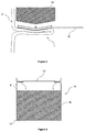
- Figure 6 illustrates a cross section through a metal can 15 storing a powder 16.
- the metal can has a flange 1 formed in the can wall 2.
- the flange 1 provides a sealing surface to which a peelable lid 12 has been heat sealed using a punch having an engagement surface with a generally V-shaped profile.
- the peelable lid 12 can comprise a tab, or similar, such that the consumer can more easily remove the peelable lid by peeling it off the flange.
- the can is provided with a non-removable base, or "can bottom", 17 which seals the opening at the bottom end of the can.
- the can may further be provided with a removable plastic overcap that is placed over the opening at the top end of the can. This plastic overcap enables the can to be reclosed once the seal has been broken and the peelable lid removed.
- the flange 1 is shown in Figure 6 as being near the open end of the metal can. However the flange may be formed lower down the can wall, thus enabling the seal to separate the can into two distinct compartments.
- the lower compartment that is hermetically sealed by the peelable lid may contain infant formula powder
- the upper compartment may contain a scoop or spoon.
- a further flange may be provided towards the top of the can to seal the section of the can containing the scoop to ensure that it is kept in a sterile environment prior to a consumer opening and using it.
- a can manufacturer may manufacture tubular metal cans with the peelable lids in place but with the bottom ends left open.
- the cans, with separate bottom ends and plastic overcaps, will then be sent to the manufacturer's customers.
- the customer can then fill the cans with product through the open bottoms before sealing the cans by seaming the non-removable can bottoms in place.
- the plastic overcaps can then be placed on the top end of the cans above the peelable lids. If required, a spoon or scoop can be placed in the can on top of the peelable lid, prior to the plastic overcap being put in place.
- Figure 7 illustrates a perspective view of a metal can 15 from above. This view shows that the flange 1 is formed in the can wall 2 part-way down its length, and that the flange extends around the entire inner circumference of the metal can 15.
- the peelable lid may be of a plastic material, or may be a multi-layer structure which includes a ceramic layer such as silica or alumina instead of metal.
Description
- The present invention relates to metal cans with peelable lids and in particular to the provision of a metal can having a flange to provide a surface for sealing the can with a peelable lid.
- Cans are typically either two-piece or three-piece cans. In the case of a two-piece can, a can body is formed by punching a metal plate to form a cylinder closed at one end. Once the can is filled, the open end is then typically closed by seaming a lid to the can body. In the case of a three-piece can, a can body, open at both ends, is formed by rolling and seaming a metal plate. A first end is closed by typically seaming a lid to the can body. Once the can is filled and the second end is closed by typically seaming a lid to the can body.
-
FR 2639561 - For some markets, the type of metal can described in
FR 2639561 -
EP 1800770 A1 discloses a method according to preamble ofclaim 1.US 6688486 also disloses a method of hermetically sealing a prelable lid to a can body. - Before being introduced into the market, such specialised metal cans are required to undergo a series of stringent tests to ensure that they meet the necessary safety requirements. For example, metal cans may be tested to ensure that they do not lose their hermetic seal even when stored at high ambient temperatures such as 45°C for periods in excess of 3 months and with a pressure difference from inside to outside of the can, for example of 700mbar (70kPa). Typically the external pressure is standard (ambient) air pressure and the internal pressure is negative, often referred to as a "vacuum". Under such conditions, it has been found that metal cans made in accordance with those described in the prior art are prone to suffering from "creep" in the seal. Creep is the tendency for the peelable lid to be pulled inward across the flange. This can reduce the effectiveness of the seal between the peelable lid and the flange, and in some cases may cause the seal to fail completely. Metal cans that suffer from creep in this way cannot be used in the infant formula market as the seal is not deemed to seal the product to a high enough standard.
- It is an object of the present invention to overcome or at least mitigate the problems discussed above which result from creep in the seal between a metal can with a flange and a peelable lid.
- According to a first embodiment of the present invention there is provided a method of sealing a peelable lid to a circumferential and inwardly projecting flange formed in a tubular metal can body, where the flange has a sealing surface having a substantially V-shaped profile, the method comprising pressing the peelable lid against the sealing surface of the flange using a punch, an engagement surface of the punch having a generally V-shaped profile such that the apex of the punch presses the peelable lid into the valley of the engagement surface of the flange.
- Heat may be applied to the peelable lid and/or the flange as the peelable lid is pressed against the sealing surface of the flange.
- Embodiments of the present invention provide an improved metal can that is capable of providing a superior hermetic seal.
- Preferably, said step of pressing the peelable lid against the sealing surface of the flange using a punch substantially eliminates air pockets from between the peelable lid and the sealing surface of the flange.
-
-
Figure 1 illustrates a cross section through part of the side wall of a can with a flange as currently known in the prior art; -
Figure 2 illustrates a cross section through part of the side wall and a punch with a generally V-shaped engagement surface at a first stage of a sealing operation according to an embodiment of the present invention; -
Figure 3 illustrates the sealing operation at a second stage; -
Figure 4 illustrates the sealing operation at a third stage; -
Figure 5 illustrates the sealing operation at a fourth stage; -
Figure 6 illustrates a cross-sectional view of a metal can body with a flange and a peelable lid sealed to the flange using the method ofFigures 2 to 5 ; and -
Figure 7 is a perspective view of a metal can body according to an embodiment of the invention. - The following discussion relates to metal cans that are provided with peelable lids that hermetically seal the can, and which can be peeled back and removed to open the can and provide access to the contents stored therein. The metal cans may be either two-piece cans or three-piece cans.
- As discussed above, known metal cans that are provided with flanges to seal with a peelable lid are often not able to be sealed to a high enough standard to pass the stringent tests required for certain high specification products, in particular infant formula powder.
-
Figure 1 illustrates a cross section through part of theside wall 2 of a metal can that has aflange 1 such as is known in the prior art. The upper surface of the flange does not provide a perfectly flat surface onto which a peelable lid can be sealed. Tests show that it is extremely difficult to obtain a completely flat upper surface on this type of flange, and typically the upper surface of the flange adopts a generally "V-shaped" profile with two radially inner and outer portions (3 and 4) being raised above an area between them at a lower level (B'). This profile arises when the initially dome shaped upper surface of the flange collapse down in the centre region (N and B'). - The horizontal dotted line A indicates that, during a typical sealing process, when a peelable lid is positioned onto the upper surface of the flange from above using a flat punch, it would in fact only seal to the upper surface of the flange at the
positions 3 and 4. There is a significant "trough" between arrows B and B' where air would be trapped between the two sealed portions at 3 and 4, thus preventing this area from being properly sealed. As a consequence, there is a substantial reduction in the overall sealing area between the peelable lid and the flange, and this greatly weakens the seal in shear mode and increases the possibility of the seal suffering from creep. - A method of sealing a peelable lid to a metal can comprising an inwardly projecting flange will now be described, with reference to
Figures 3 to 5 , and which enables the formation of a substantially continuous seal across the radial extent of the flange in order to achieve a more robust seal. This is facilitated by using a punch that has an engagement surface having a generally V-shaped profile to press the peelable lid against the flange sealing surface. The generally V-shaped engagement surface of the punch reduces the size of, or even eliminates, "pockets" of trapped air between the peelable lid and the upper surface of the flange. -
Figure 2 illustrates in cross section a part of theside wall 2 of a metal can and apunch 10 at the start of a sealing operation in which thepeelable lid 12 is "punched" into place. Thepunch 10 has a generally V-shaped engagement surface 11 which approximately conforms with the generally V-shaped profile of the sealing surface of theflange 1. [It will be appreciated that thepunch 10 is generally ring shaped for insertion into the can body such that in use it extends around the inner periphery of the can body for engagement with the flange.] - During the heat sealing process, the
punch 10 presses thepeelable lid 12 down on theflange 1 using a force F. The seal is formed initially in the middle of the radial extent of theflange 1 at point P where the apex of thepunch 10 presses thepeelable lid 12 into the trough of the engagement surface of theflange 1. Then, as shown inFigure 3 , as the punch is pressed down onto the flange, thepeelable lid 12 adopts the V-shaped profile of thepunch 10, and a seal is formed between thepeelable lid 12 and theflange 1. - The seal is made using a heat-sealable material, for example a thermoplastic material, located between the peelable lid and the convex upper surface of the flange. The V-shaped profile of the engagement surface of the
punch 10 allows any air that would otherwise be trapped, to escape from between the peelable lid and the sealing surface of the flange at each of the sides before the full seal is made across substantially the whole radial extent of the flange. - As illustrated in
Figure 4 , the shape of the sealing surface of the flange may also be changed by the pressure applied by thepunch 10. This can further reduce the extent of the non-sealed areas between the peelable lid and the sealing surface of the flange. -
Figure 5 illustrates a cross section of the wall of the metal can 2 after thepeelable lid 12 has been heat-sealed to the sealing surface of theflange 1 and thepunch 10 withdrawn. The arrow S shows the substantially uninterrupted width of the seal that is formed over most of the radial extent of the flange. -
Figure 6 illustrates a cross section through a metal can 15 storing apowder 16. The metal can has aflange 1 formed in thecan wall 2. Theflange 1 provides a sealing surface to which apeelable lid 12 has been heat sealed using a punch having an engagement surface with a generally V-shaped profile. Thepeelable lid 12 can comprise a tab, or similar, such that the consumer can more easily remove the peelable lid by peeling it off the flange. The can is provided with a non-removable base, or "can bottom", 17 which seals the opening at the bottom end of the can. Although not shown inFigure 6 , the can may further be provided with a removable plastic overcap that is placed over the opening at the top end of the can. This plastic overcap enables the can to be reclosed once the seal has been broken and the peelable lid removed. - The
flange 1 is shown inFigure 6 as being near the open end of the metal can. However the flange may be formed lower down the can wall, thus enabling the seal to separate the can into two distinct compartments. For example, the lower compartment that is hermetically sealed by the peelable lid may contain infant formula powder, and the upper compartment may contain a scoop or spoon. A further flange may be provided towards the top of the can to seal the section of the can containing the scoop to ensure that it is kept in a sterile environment prior to a consumer opening and using it. - It is also possible to form flanges at both open ends of a tubular can body (which has a welded side seam) and to close both ends with respective peelable lids.
- During the manufacturing process for cans such as those described herein, a can manufacturer may manufacture tubular metal cans with the peelable lids in place but with the bottom ends left open. The cans, with separate bottom ends and plastic overcaps, will then be sent to the manufacturer's customers. The customer can then fill the cans with product through the open bottoms before sealing the cans by seaming the non-removable can bottoms in place. The plastic overcaps can then be placed on the top end of the cans above the peelable lids. If required, a spoon or scoop can be placed in the can on top of the peelable lid, prior to the plastic overcap being put in place.
-
Figure 7 illustrates a perspective view of a metal can 15 from above. This view shows that theflange 1 is formed in the can wall 2 part-way down its length, and that the flange extends around the entire inner circumference of the metal can 15. - It will be appreciated by the person of skill in the art that various modifications may be made to the above described embodiments without departing from the scope of the present invention. For example, the peelable lid may be of a plastic material, or may be a multi-layer structure which includes a ceramic layer such as silica or alumina instead of metal.
Claims (3)
- A method of hermetically sealing a peelable lid (12) to a circumferential and inwardly projecting flange (1) formed in a tubular metal can body, characterised in that the flange (1) has a sealing surface having a substantially V-shaped profile, the method comprising pressing the peelable lid (12) against the sealing surface of the flange (1) using a punch (10), an engagement surface of the punch (10) having a substantially V-shaped profile such that the apex of the punch (10) presses the peelable lid (12) into the valley of the sealing surface of the flange (1).
- A method according to claim 1, wherein heat is applied to the peelable lid (12) and/or the flange (1) as the peelable lid is pressed against the flange.
- A method according to claim 1 or 2, wherein said step of pressing the peelable lid (12) against the sealing surface of the flange (1) using a punch (10) substantially eliminates air pockets from between the peelable lid (12) and the sealing surface of the flange (1).
Applications Claiming Priority (2)
| Application Number | Priority Date | Filing Date | Title |
|---|---|---|---|
| GBGB1214716.1A GB201214716D0 (en) | 2012-08-17 | 2012-08-17 | Metal cans with peelable lids |
| PCT/GB2013/052093 WO2014027180A1 (en) | 2012-08-17 | 2013-08-06 | Metal cans with peelable lids |
Publications (2)
| Publication Number | Publication Date |
|---|---|
| EP2885123A1 EP2885123A1 (en) | 2015-06-24 |
| EP2885123B1 true EP2885123B1 (en) | 2016-07-13 |
Family
ID=47016949
Family Applications (1)
| Application Number | Title | Priority Date | Filing Date |
|---|---|---|---|
| EP13750097.1A Not-in-force EP2885123B1 (en) | 2012-08-17 | 2013-08-06 | Metal cans with peelable lids |
Country Status (8)
| Country | Link |
|---|---|
| US (1) | US9932152B2 (en) |
| EP (1) | EP2885123B1 (en) |
| CN (1) | CN104540661B (en) |
| CA (1) | CA2879790C (en) |
| ES (1) | ES2596242T3 (en) |
| GB (1) | GB201214716D0 (en) |
| MX (1) | MX356587B (en) |
| WO (1) | WO2014027180A1 (en) |
Families Citing this family (9)
| Publication number | Priority date | Publication date | Assignee | Title |
|---|---|---|---|---|
| GB2536265B (en) * | 2015-03-11 | 2018-01-24 | Crown Packaging Technology Inc | Ringless metal cans |
| US10875076B2 (en) | 2017-02-07 | 2020-12-29 | Ball Corporation | Tapered metal cup and method of forming the same |
| US11370579B2 (en) | 2017-02-07 | 2022-06-28 | Ball Corporation | Tapered metal cup and method of forming the same |
| USD950318S1 (en) | 2018-05-24 | 2022-05-03 | Ball Corporation | Tapered cup |
| USD906056S1 (en) | 2018-12-05 | 2020-12-29 | Ball Corporation | Tapered cup |
| USD968893S1 (en) | 2019-06-24 | 2022-11-08 | Ball Corporation | Tapered cup |
| USD953811S1 (en) | 2020-02-14 | 2022-06-07 | Ball Corporation | Tapered cup |
| USD974845S1 (en) | 2020-07-15 | 2023-01-10 | Ball Corporation | Tapered cup |
| USD1012617S1 (en) | 2021-02-22 | 2024-01-30 | Ball Corporation | Tapered cup |
Citations (1)
| Publication number | Priority date | Publication date | Assignee | Title |
|---|---|---|---|---|
| US6688486B2 (en) * | 2000-09-12 | 2004-02-10 | George B. Diamond | Easy open end and can for powders |
Family Cites Families (11)
| Publication number | Priority date | Publication date | Assignee | Title |
|---|---|---|---|---|
| FR1544071A (en) | 1967-08-30 | 1968-10-31 | Bellaplast Gmbh | Device for sealing a lid on thermoplastic synthetic containers |
| DE2116179C3 (en) * | 1971-04-02 | 1974-01-10 | Ohler Eisenwerk, Theob. Pfeiffer, 5970 Plettenberg | Method and device for closing containers filled with food |
| DE2718574A1 (en) | 1977-04-26 | 1978-11-02 | Honshu Paper Co Ltd | Heat sealed liq. container - with flanged end seal bonded to body along part of flanged area only |
| BR8604254A (en) * | 1985-09-30 | 1987-04-28 | Emerson Electric Co | SAFETY BREATHING PROCESS IN HERMETICALLY SEALED CONTAINER LID, SAFETY BREATHING MANUFACTURE PROCESS IN METAL COVERS FOR HERMETICALLY SEALED BATTERY CONTAINERS, HERMOTICALLY HERMITICALLY SEALED CONTAINER |
| FR2639561B1 (en) | 1988-11-29 | 1994-05-20 | Carnaud Sa | METHOD FOR MANUFACTURING A FLEXIBLE LID METAL PACKAGE AND CORRESPONDING METAL PACKAGE |
| CN2055127U (en) * | 1989-08-03 | 1990-03-28 | 南昌市罐头啤酒厂 | Plastic dripping bottle cap |
| FR2762304B1 (en) * | 1997-04-21 | 1999-05-28 | Pechiney Emballage Alimentaire | PLASTIC SLEEVE CAPSULE |
| EP2143509B1 (en) | 2005-03-01 | 2017-11-15 | Crown Packaging Technology, Inc. | Method and apparatus for manufacturing a metal can |
| EP1800770A1 (en) | 2005-12-23 | 2007-06-27 | Crown Packaging Technology, Inc | Can body with a sealing compound placed on a step or flange and method of forming such a can body |
| DK2052984T3 (en) * | 2007-10-25 | 2011-02-07 | Impress Group Bv | Method of preparing and forming a lid and lid |
| US20110272417A1 (en) * | 2010-03-17 | 2011-11-10 | Silgan Containers Llc | Container with internal strainer |
-
2012
- 2012-08-17 GB GBGB1214716.1A patent/GB201214716D0/en not_active Ceased
-
2013
- 2013-08-06 WO PCT/GB2013/052093 patent/WO2014027180A1/en active Application Filing
- 2013-08-06 MX MX2015002033A patent/MX356587B/en active IP Right Grant
- 2013-08-06 EP EP13750097.1A patent/EP2885123B1/en not_active Not-in-force
- 2013-08-06 US US14/421,460 patent/US9932152B2/en active Active
- 2013-08-06 CN CN201380042162.5A patent/CN104540661B/en active Active
- 2013-08-06 CA CA2879790A patent/CA2879790C/en active Active
- 2013-08-06 ES ES13750097.1T patent/ES2596242T3/en active Active
Patent Citations (1)
| Publication number | Priority date | Publication date | Assignee | Title |
|---|---|---|---|---|
| US6688486B2 (en) * | 2000-09-12 | 2004-02-10 | George B. Diamond | Easy open end and can for powders |
Also Published As
| Publication number | Publication date |
|---|---|
| EP2885123A1 (en) | 2015-06-24 |
| MX356587B (en) | 2018-06-05 |
| ES2596242T3 (en) | 2017-01-05 |
| US20150217907A1 (en) | 2015-08-06 |
| MX2015002033A (en) | 2015-06-05 |
| WO2014027180A1 (en) | 2014-02-20 |
| CA2879790C (en) | 2021-03-09 |
| CA2879790A1 (en) | 2014-02-20 |
| CN104540661A (en) | 2015-04-22 |
| US9932152B2 (en) | 2018-04-03 |
| CN104540661B (en) | 2017-11-10 |
| GB201214716D0 (en) | 2012-10-03 |
Similar Documents
| Publication | Publication Date | Title |
|---|---|---|
| EP2885123B1 (en) | Metal cans with peelable lids | |
| CA2840938C (en) | Metal cans with peelable lids | |
| KR920005141B1 (en) | Containers | |
| RU2433044C2 (en) | Container cap provided with tear-off membrane | |
| US4213538A (en) | Can end closure | |
| US20120043324A1 (en) | Container with Reduced, Peel-Off-Force Tear Configuration | |
| US6116500A (en) | Composite container | |
| JP4133436B2 (en) | Easy-open packaging body and method for producing easy-open packaging body | |
| US20110272417A1 (en) | Container with internal strainer | |
| NZ283259A (en) | Multiple compartment package suitable for two different articles of food | |
| US10610918B2 (en) | Method and device for the manufacture of a can with a tear-open lid and can with a tear-open lid | |
| US11718446B2 (en) | Container for hermetically sealed storage of products, in particular foodstuffs | |
| EP2271562B1 (en) | Lid with barrier property | |
| EP1800770A1 (en) | Can body with a sealing compound placed on a step or flange and method of forming such a can body | |
| IE47405B1 (en) | Containers | |
| US3208626A (en) | Container closure and package including same | |
| US20050029267A1 (en) | Container having a cut panel lid with a pull feature | |
| AU2005206169A1 (en) | Angled sealing surface for container end panel | |
| US6325232B1 (en) | Process for producing a filled container and filled container | |
| US6244020B1 (en) | Process for producing a filled container and filled container | |
| AU720130B2 (en) | Process for producing a filled container | |
| WO2014130170A1 (en) | Induction heat sealed container closures | |
| EP1127010B1 (en) | Sealable container | |
| JP2003072843A (en) | Food packaging body using easily openable container made of synthetic resin | |
| MXPA00008617A (en) | Easy-open composite container with a membrane-type closure |
Legal Events
| Date | Code | Title | Description |
|---|---|---|---|
| PUAI | Public reference made under article 153(3) epc to a published international application that has entered the european phase |
Free format text: ORIGINAL CODE: 0009012 |
|
| 17P | Request for examination filed |
Effective date: 20150116 |
|
| AK | Designated contracting states |
Kind code of ref document: A1 Designated state(s): AL AT BE BG CH CY CZ DE DK EE ES FI FR GB GR HR HU IE IS IT LI LT LU LV MC MK MT NL NO PL PT RO RS SE SI SK SM TR |
|
| AX | Request for extension of the european patent |
Extension state: BA ME |
|
| DAX | Request for extension of the european patent (deleted) | ||
| REG | Reference to a national code |
Ref country code: DE Ref legal event code: R079 Ref document number: 602013009422 Country of ref document: DE Free format text: PREVIOUS MAIN CLASS: B29C0065000000 Ipc: B29L0031000000 |
|
| GRAP | Despatch of communication of intention to grant a patent |
Free format text: ORIGINAL CODE: EPIDOSNIGR1 |
|
| RIC1 | Information provided on ipc code assigned before grant |
Ipc: B65B 7/28 20060101ALI20160108BHEP Ipc: B29L 31/00 20060101AFI20160108BHEP Ipc: B29C 65/18 20060101ALI20160108BHEP Ipc: B65D 1/40 20060101ALI20160108BHEP Ipc: B32B 38/00 20060101ALI20160108BHEP Ipc: B65D 43/02 20060101ALI20160108BHEP Ipc: B29C 65/00 20060101ALI20160108BHEP Ipc: B65D 17/50 20060101ALI20160108BHEP Ipc: B29C 65/76 20060101ALI20160108BHEP Ipc: B65D 1/12 20060101ALI20160108BHEP Ipc: B32B 37/18 20060101ALI20160108BHEP |
|
| INTG | Intention to grant announced |
Effective date: 20160202 |
|
| GRAS | Grant fee paid |
Free format text: ORIGINAL CODE: EPIDOSNIGR3 |
|
| GRAA | (expected) grant |
Free format text: ORIGINAL CODE: 0009210 |
|
| AK | Designated contracting states |
Kind code of ref document: B1 Designated state(s): AL AT BE BG CH CY CZ DE DK EE ES FI FR GB GR HR HU IE IS IT LI LT LU LV MC MK MT NL NO PL PT RO RS SE SI SK SM TR |
|
| REG | Reference to a national code |
Ref country code: GB Ref legal event code: FG4D |
|
| REG | Reference to a national code |
Ref country code: AT Ref legal event code: REF Ref document number: 811934 Country of ref document: AT Kind code of ref document: T Effective date: 20160715 Ref country code: CH Ref legal event code: EP |
|
| REG | Reference to a national code |
Ref country code: IE Ref legal event code: FG4D |
|
| REG | Reference to a national code |
Ref country code: FR Ref legal event code: PLFP Year of fee payment: 4 |
|
| REG | Reference to a national code |
Ref country code: DE Ref legal event code: R096 Ref document number: 602013009422 Country of ref document: DE |
|
| REG | Reference to a national code |
Ref country code: NL Ref legal event code: FP |
|
| REG | Reference to a national code |
Ref country code: LT Ref legal event code: MG4D |
|
| REG | Reference to a national code |
Ref country code: AT Ref legal event code: MK05 Ref document number: 811934 Country of ref document: AT Kind code of ref document: T Effective date: 20160713 |
|
| PG25 | Lapsed in a contracting state [announced via postgrant information from national office to epo] |
Ref country code: BE Free format text: LAPSE BECAUSE OF NON-PAYMENT OF DUE FEES Effective date: 20160831 |
|
| REG | Reference to a national code |
Ref country code: ES Ref legal event code: FG2A Ref document number: 2596242 Country of ref document: ES Kind code of ref document: T3 Effective date: 20170105 |
|
| PG25 | Lapsed in a contracting state [announced via postgrant information from national office to epo] |
Ref country code: RS Free format text: LAPSE BECAUSE OF FAILURE TO SUBMIT A TRANSLATION OF THE DESCRIPTION OR TO PAY THE FEE WITHIN THE PRESCRIBED TIME-LIMIT Effective date: 20160713 Ref country code: FI Free format text: LAPSE BECAUSE OF FAILURE TO SUBMIT A TRANSLATION OF THE DESCRIPTION OR TO PAY THE FEE WITHIN THE PRESCRIBED TIME-LIMIT Effective date: 20160713 Ref country code: HR Free format text: LAPSE BECAUSE OF FAILURE TO SUBMIT A TRANSLATION OF THE DESCRIPTION OR TO PAY THE FEE WITHIN THE PRESCRIBED TIME-LIMIT Effective date: 20160713 Ref country code: LT Free format text: LAPSE BECAUSE OF FAILURE TO SUBMIT A TRANSLATION OF THE DESCRIPTION OR TO PAY THE FEE WITHIN THE PRESCRIBED TIME-LIMIT Effective date: 20160713 Ref country code: NO Free format text: LAPSE BECAUSE OF FAILURE TO SUBMIT A TRANSLATION OF THE DESCRIPTION OR TO PAY THE FEE WITHIN THE PRESCRIBED TIME-LIMIT Effective date: 20161013 Ref country code: IS Free format text: LAPSE BECAUSE OF FAILURE TO SUBMIT A TRANSLATION OF THE DESCRIPTION OR TO PAY THE FEE WITHIN THE PRESCRIBED TIME-LIMIT Effective date: 20161113 |
|
| PG25 | Lapsed in a contracting state [announced via postgrant information from national office to epo] |
Ref country code: AT Free format text: LAPSE BECAUSE OF FAILURE TO SUBMIT A TRANSLATION OF THE DESCRIPTION OR TO PAY THE FEE WITHIN THE PRESCRIBED TIME-LIMIT Effective date: 20160713 Ref country code: LV Free format text: LAPSE BECAUSE OF FAILURE TO SUBMIT A TRANSLATION OF THE DESCRIPTION OR TO PAY THE FEE WITHIN THE PRESCRIBED TIME-LIMIT Effective date: 20160713 Ref country code: PL Free format text: LAPSE BECAUSE OF FAILURE TO SUBMIT A TRANSLATION OF THE DESCRIPTION OR TO PAY THE FEE WITHIN THE PRESCRIBED TIME-LIMIT Effective date: 20160713 Ref country code: GR Free format text: LAPSE BECAUSE OF FAILURE TO SUBMIT A TRANSLATION OF THE DESCRIPTION OR TO PAY THE FEE WITHIN THE PRESCRIBED TIME-LIMIT Effective date: 20161014 Ref country code: SE Free format text: LAPSE BECAUSE OF FAILURE TO SUBMIT A TRANSLATION OF THE DESCRIPTION OR TO PAY THE FEE WITHIN THE PRESCRIBED TIME-LIMIT Effective date: 20160713 Ref country code: PT Free format text: LAPSE BECAUSE OF FAILURE TO SUBMIT A TRANSLATION OF THE DESCRIPTION OR TO PAY THE FEE WITHIN THE PRESCRIBED TIME-LIMIT Effective date: 20161114 Ref country code: BE Free format text: LAPSE BECAUSE OF FAILURE TO SUBMIT A TRANSLATION OF THE DESCRIPTION OR TO PAY THE FEE WITHIN THE PRESCRIBED TIME-LIMIT Effective date: 20160713 |
|
| REG | Reference to a national code |
Ref country code: CH Ref legal event code: PL |
|
| REG | Reference to a national code |
Ref country code: DE Ref legal event code: R097 Ref document number: 602013009422 Country of ref document: DE |
|
| PG25 | Lapsed in a contracting state [announced via postgrant information from national office to epo] |
Ref country code: EE Free format text: LAPSE BECAUSE OF FAILURE TO SUBMIT A TRANSLATION OF THE DESCRIPTION OR TO PAY THE FEE WITHIN THE PRESCRIBED TIME-LIMIT Effective date: 20160713 Ref country code: CH Free format text: LAPSE BECAUSE OF NON-PAYMENT OF DUE FEES Effective date: 20160831 Ref country code: MC Free format text: LAPSE BECAUSE OF FAILURE TO SUBMIT A TRANSLATION OF THE DESCRIPTION OR TO PAY THE FEE WITHIN THE PRESCRIBED TIME-LIMIT Effective date: 20160713 Ref country code: RO Free format text: LAPSE BECAUSE OF FAILURE TO SUBMIT A TRANSLATION OF THE DESCRIPTION OR TO PAY THE FEE WITHIN THE PRESCRIBED TIME-LIMIT Effective date: 20160713 Ref country code: LI Free format text: LAPSE BECAUSE OF NON-PAYMENT OF DUE FEES Effective date: 20160831 |
|
| PLBE | No opposition filed within time limit |
Free format text: ORIGINAL CODE: 0009261 |
|
| STAA | Information on the status of an ep patent application or granted ep patent |
Free format text: STATUS: NO OPPOSITION FILED WITHIN TIME LIMIT |
|
| PG25 | Lapsed in a contracting state [announced via postgrant information from national office to epo] |
Ref country code: SM Free format text: LAPSE BECAUSE OF FAILURE TO SUBMIT A TRANSLATION OF THE DESCRIPTION OR TO PAY THE FEE WITHIN THE PRESCRIBED TIME-LIMIT Effective date: 20160713 Ref country code: CZ Free format text: LAPSE BECAUSE OF FAILURE TO SUBMIT A TRANSLATION OF THE DESCRIPTION OR TO PAY THE FEE WITHIN THE PRESCRIBED TIME-LIMIT Effective date: 20160713 Ref country code: SK Free format text: LAPSE BECAUSE OF FAILURE TO SUBMIT A TRANSLATION OF THE DESCRIPTION OR TO PAY THE FEE WITHIN THE PRESCRIBED TIME-LIMIT Effective date: 20160713 Ref country code: BG Free format text: LAPSE BECAUSE OF FAILURE TO SUBMIT A TRANSLATION OF THE DESCRIPTION OR TO PAY THE FEE WITHIN THE PRESCRIBED TIME-LIMIT Effective date: 20161013 Ref country code: DK Free format text: LAPSE BECAUSE OF FAILURE TO SUBMIT A TRANSLATION OF THE DESCRIPTION OR TO PAY THE FEE WITHIN THE PRESCRIBED TIME-LIMIT Effective date: 20160713 |
|
| REG | Reference to a national code |
Ref country code: IE Ref legal event code: MM4A |
|
| 26N | No opposition filed |
Effective date: 20170418 |
|
| PG25 | Lapsed in a contracting state [announced via postgrant information from national office to epo] |
Ref country code: IE Free format text: LAPSE BECAUSE OF NON-PAYMENT OF DUE FEES Effective date: 20160806 |
|
| REG | Reference to a national code |
Ref country code: FR Ref legal event code: PLFP Year of fee payment: 5 |
|
| PG25 | Lapsed in a contracting state [announced via postgrant information from national office to epo] |
Ref country code: SI Free format text: LAPSE BECAUSE OF FAILURE TO SUBMIT A TRANSLATION OF THE DESCRIPTION OR TO PAY THE FEE WITHIN THE PRESCRIBED TIME-LIMIT Effective date: 20160713 Ref country code: LU Free format text: LAPSE BECAUSE OF NON-PAYMENT OF DUE FEES Effective date: 20160806 |
|
| PG25 | Lapsed in a contracting state [announced via postgrant information from national office to epo] |
Ref country code: HU Free format text: LAPSE BECAUSE OF FAILURE TO SUBMIT A TRANSLATION OF THE DESCRIPTION OR TO PAY THE FEE WITHIN THE PRESCRIBED TIME-LIMIT; INVALID AB INITIO Effective date: 20130806 |
|
| PG25 | Lapsed in a contracting state [announced via postgrant information from national office to epo] |
Ref country code: CY Free format text: LAPSE BECAUSE OF FAILURE TO SUBMIT A TRANSLATION OF THE DESCRIPTION OR TO PAY THE FEE WITHIN THE PRESCRIBED TIME-LIMIT Effective date: 20160713 Ref country code: MK Free format text: LAPSE BECAUSE OF FAILURE TO SUBMIT A TRANSLATION OF THE DESCRIPTION OR TO PAY THE FEE WITHIN THE PRESCRIBED TIME-LIMIT Effective date: 20160713 Ref country code: MT Free format text: LAPSE BECAUSE OF NON-PAYMENT OF DUE FEES Effective date: 20160831 |
|
| REG | Reference to a national code |
Ref country code: FR Ref legal event code: PLFP Year of fee payment: 6 |
|
| PG25 | Lapsed in a contracting state [announced via postgrant information from national office to epo] |
Ref country code: TR Free format text: LAPSE BECAUSE OF FAILURE TO SUBMIT A TRANSLATION OF THE DESCRIPTION OR TO PAY THE FEE WITHIN THE PRESCRIBED TIME-LIMIT Effective date: 20160713 Ref country code: AL Free format text: LAPSE BECAUSE OF FAILURE TO SUBMIT A TRANSLATION OF THE DESCRIPTION OR TO PAY THE FEE WITHIN THE PRESCRIBED TIME-LIMIT Effective date: 20160713 |
|
| PGFP | Annual fee paid to national office [announced via postgrant information from national office to epo] |
Ref country code: NL Payment date: 20210819 Year of fee payment: 9 |
|
| PGFP | Annual fee paid to national office [announced via postgrant information from national office to epo] |
Ref country code: IT Payment date: 20210824 Year of fee payment: 9 Ref country code: FR Payment date: 20210819 Year of fee payment: 9 |
|
| PGFP | Annual fee paid to national office [announced via postgrant information from national office to epo] |
Ref country code: GB Payment date: 20210820 Year of fee payment: 9 Ref country code: DE Payment date: 20210819 Year of fee payment: 9 |
|
| PGFP | Annual fee paid to national office [announced via postgrant information from national office to epo] |
Ref country code: ES Payment date: 20211026 Year of fee payment: 9 |
|
| REG | Reference to a national code |
Ref country code: GB Ref legal event code: 732E Free format text: REGISTERED BETWEEN 20220210 AND 20220216 |
|
| REG | Reference to a national code |
Ref country code: DE Ref legal event code: R081 Ref document number: 602013009422 Country of ref document: DE Owner name: EVIOSYS PACKAGING SWITZERLAND GMBH, CH Free format text: FORMER OWNER: CROWN PACKAGING TECHNOLOGY, INC., ALSIP, ILL., US Ref country code: DE Ref legal event code: R082 Ref document number: 602013009422 Country of ref document: DE Representative=s name: PATENTANWALTSKANZLEI LIERMANN-CASTELL, DE |
|
| REG | Reference to a national code |
Ref country code: NL Ref legal event code: PD Owner name: EVIOSYS PACKAGING SWITZERLAND GMBH; CH Free format text: DETAILS ASSIGNMENT: CHANGE OF OWNER(S), ASSIGNMENT; FORMER OWNER NAME: CROWN PACKAGING TECHNOLOGY, INC. Effective date: 20220601 |
|
| REG | Reference to a national code |
Ref country code: DE Ref legal event code: R119 Ref document number: 602013009422 Country of ref document: DE |
|
| REG | Reference to a national code |
Ref country code: NL Ref legal event code: MM Effective date: 20220901 |
|
| GBPC | Gb: european patent ceased through non-payment of renewal fee |
Effective date: 20220806 |
|
| REG | Reference to a national code |
Ref country code: ES Ref legal event code: PC2A Owner name: EVIOSYS PACKAGING SWITZERLAND GMBH. Effective date: 20230614 |
|
| P01 | Opt-out of the competence of the unified patent court (upc) registered |
Effective date: 20230515 |
|
| PG25 | Lapsed in a contracting state [announced via postgrant information from national office to epo] |
Ref country code: NL Free format text: LAPSE BECAUSE OF NON-PAYMENT OF DUE FEES Effective date: 20220901 |
|
| PG25 | Lapsed in a contracting state [announced via postgrant information from national office to epo] |
Ref country code: IT Free format text: LAPSE BECAUSE OF NON-PAYMENT OF DUE FEES Effective date: 20220806 Ref country code: FR Free format text: LAPSE BECAUSE OF NON-PAYMENT OF DUE FEES Effective date: 20220831 Ref country code: DE Free format text: LAPSE BECAUSE OF NON-PAYMENT OF DUE FEES Effective date: 20230301 |
|
| REG | Reference to a national code |
Ref country code: ES Ref legal event code: FD2A Effective date: 20230926 |
|
| PG25 | Lapsed in a contracting state [announced via postgrant information from national office to epo] |
Ref country code: GB Free format text: LAPSE BECAUSE OF NON-PAYMENT OF DUE FEES Effective date: 20220806 Ref country code: ES Free format text: LAPSE BECAUSE OF NON-PAYMENT OF DUE FEES Effective date: 20220807 |