EP2884903B1 - Systeme und werkzeuge für den anschluss an gewebe - Google Patents
Systeme und werkzeuge für den anschluss an gewebe Download PDFInfo
- Publication number
- EP2884903B1 EP2884903B1 EP13823116.2A EP13823116A EP2884903B1 EP 2884903 B1 EP2884903 B1 EP 2884903B1 EP 13823116 A EP13823116 A EP 13823116A EP 2884903 B1 EP2884903 B1 EP 2884903B1
- Authority
- EP
- European Patent Office
- Prior art keywords
- anchor
- leg
- tissue
- staging
- soft tissue
- Prior art date
- Legal status (The legal status is an assumption and is not a legal conclusion. Google has not performed a legal analysis and makes no representation as to the accuracy of the status listed.)
- Not-in-force
Links
- 210000001519 tissue Anatomy 0.000 claims description 222
- 210000004872 soft tissue Anatomy 0.000 claims description 123
- 230000003319 supportive effect Effects 0.000 claims description 17
- 229920002457 flexible plastic Polymers 0.000 claims description 2
- 239000007943 implant Substances 0.000 description 113
- 238000000034 method Methods 0.000 description 81
- 239000000463 material Substances 0.000 description 58
- 230000007246 mechanism Effects 0.000 description 31
- 206010019909 Hernia Diseases 0.000 description 21
- 206010021639 Incontinence Diseases 0.000 description 11
- 208000012287 Prolapse Diseases 0.000 description 11
- 230000003187 abdominal effect Effects 0.000 description 11
- 210000003205 muscle Anatomy 0.000 description 11
- 208000013823 pelvic organ prolapse Diseases 0.000 description 11
- 210000003041 ligament Anatomy 0.000 description 9
- 201000004989 Enterocele Diseases 0.000 description 8
- 206010046814 Uterine prolapse Diseases 0.000 description 8
- 210000004197 pelvis Anatomy 0.000 description 8
- 229920003023 plastic Polymers 0.000 description 8
- 239000004033 plastic Substances 0.000 description 8
- 238000001356 surgical procedure Methods 0.000 description 8
- 210000003708 urethra Anatomy 0.000 description 8
- 208000002847 Surgical Wound Diseases 0.000 description 7
- 206010046543 Urinary incontinence Diseases 0.000 description 7
- 206010046940 Vaginal prolapse Diseases 0.000 description 7
- 210000003484 anatomy Anatomy 0.000 description 7
- 238000002316 cosmetic surgery Methods 0.000 description 7
- 206010011803 Cystocele Diseases 0.000 description 6
- -1 polypropylene Polymers 0.000 description 6
- 238000011282 treatment Methods 0.000 description 6
- 230000002485 urinary effect Effects 0.000 description 6
- 208000034347 Faecal incontinence Diseases 0.000 description 5
- 206010038084 Rectocele Diseases 0.000 description 5
- 210000003195 fascia Anatomy 0.000 description 5
- 210000004446 longitudinal ligament Anatomy 0.000 description 5
- 239000004743 Polypropylene Substances 0.000 description 4
- 210000001015 abdomen Anatomy 0.000 description 4
- 238000004873 anchoring Methods 0.000 description 4
- 238000004891 communication Methods 0.000 description 4
- 239000003814 drug Substances 0.000 description 4
- 230000002550 fecal effect Effects 0.000 description 4
- 238000003780 insertion Methods 0.000 description 4
- 230000037431 insertion Effects 0.000 description 4
- 229920001155 polypropylene Polymers 0.000 description 4
- 241001465754 Metazoa Species 0.000 description 3
- 229920000954 Polyglycolide Polymers 0.000 description 3
- 210000000988 bone and bone Anatomy 0.000 description 3
- 230000007547 defect Effects 0.000 description 3
- 239000002184 metal Substances 0.000 description 3
- 229920000747 poly(lactic acid) Polymers 0.000 description 3
- 239000004633 polyglycolic acid Substances 0.000 description 3
- 239000000725 suspension Substances 0.000 description 3
- 206010053236 Mixed incontinence Diseases 0.000 description 2
- 239000004698 Polyethylene Substances 0.000 description 2
- 206010066218 Stress Urinary Incontinence Diseases 0.000 description 2
- 208000000921 Urge Urinary Incontinence Diseases 0.000 description 2
- 210000003489 abdominal muscle Anatomy 0.000 description 2
- 239000012620 biological material Substances 0.000 description 2
- 230000006378 damage Effects 0.000 description 2
- 208000037265 diseases, disorders, signs and symptoms Diseases 0.000 description 2
- 208000035475 disorder Diseases 0.000 description 2
- 238000002682 general surgery Methods 0.000 description 2
- 238000009802 hysterectomy Methods 0.000 description 2
- 238000009434 installation Methods 0.000 description 2
- 229920000573 polyethylene Polymers 0.000 description 2
- 210000002435 tendon Anatomy 0.000 description 2
- 206010046494 urge incontinence Diseases 0.000 description 2
- 210000004291 uterus Anatomy 0.000 description 2
- 210000001215 vagina Anatomy 0.000 description 2
- 206010003694 Atrophy Diseases 0.000 description 1
- 208000023610 Pelvic Floor disease Diseases 0.000 description 1
- 206010034268 Pelvic prolapse Diseases 0.000 description 1
- 229920004738 ULTEM® Polymers 0.000 description 1
- 208000027418 Wounds and injury Diseases 0.000 description 1
- 238000012084 abdominal surgery Methods 0.000 description 1
- 239000000853 adhesive Substances 0.000 description 1
- 230000001070 adhesive effect Effects 0.000 description 1
- 230000032683 aging Effects 0.000 description 1
- 230000000712 assembly Effects 0.000 description 1
- 238000000429 assembly Methods 0.000 description 1
- 230000037444 atrophy Effects 0.000 description 1
- 229920000249 biocompatible polymer Polymers 0.000 description 1
- 210000003679 cervix uteri Anatomy 0.000 description 1
- 210000002808 connective tissue Anatomy 0.000 description 1
- 239000000470 constituent Substances 0.000 description 1
- 229920001577 copolymer Polymers 0.000 description 1
- 230000001419 dependent effect Effects 0.000 description 1
- 229920002313 fluoropolymer Polymers 0.000 description 1
- 239000004811 fluoropolymer Substances 0.000 description 1
- 208000014674 injury Diseases 0.000 description 1
- 210000002414 leg Anatomy 0.000 description 1
- 210000004379 membrane Anatomy 0.000 description 1
- 239000012528 membrane Substances 0.000 description 1
- HLXZNVUGXRDIFK-UHFFFAOYSA-N nickel titanium Chemical compound [Ti].[Ti].[Ti].[Ti].[Ti].[Ti].[Ti].[Ti].[Ti].[Ti].[Ti].[Ni].[Ni].[Ni].[Ni].[Ni].[Ni].[Ni].[Ni].[Ni].[Ni].[Ni].[Ni].[Ni].[Ni] HLXZNVUGXRDIFK-UHFFFAOYSA-N 0.000 description 1
- 229910001000 nickel titanium Inorganic materials 0.000 description 1
- 210000000056 organ Anatomy 0.000 description 1
- 208000024449 overflow incontinence Diseases 0.000 description 1
- 210000003903 pelvic floor Anatomy 0.000 description 1
- 210000004303 peritoneum Anatomy 0.000 description 1
- 229920002492 poly(sulfone) Polymers 0.000 description 1
- 229920000515 polycarbonate Polymers 0.000 description 1
- 239000004417 polycarbonate Substances 0.000 description 1
- 229920000139 polyethylene terephthalate Polymers 0.000 description 1
- 239000005020 polyethylene terephthalate Substances 0.000 description 1
- 229920001296 polysiloxane Polymers 0.000 description 1
- 229920002635 polyurethane Polymers 0.000 description 1
- 239000004814 polyurethane Substances 0.000 description 1
- 230000002035 prolonged effect Effects 0.000 description 1
- 210000000664 rectum Anatomy 0.000 description 1
- 238000011160 research Methods 0.000 description 1
- 238000012827 research and development Methods 0.000 description 1
- 239000007787 solid Substances 0.000 description 1
- 210000005070 sphincter Anatomy 0.000 description 1
- 229910001220 stainless steel Inorganic materials 0.000 description 1
- 239000010935 stainless steel Substances 0.000 description 1
- 210000002784 stomach Anatomy 0.000 description 1
- 239000003356 suture material Substances 0.000 description 1
- 230000001225 therapeutic effect Effects 0.000 description 1
- 229920001169 thermoplastic Polymers 0.000 description 1
- 239000004416 thermosoftening plastic Substances 0.000 description 1
- 238000012546 transfer Methods 0.000 description 1
Images





Classifications
-
- A—HUMAN NECESSITIES
- A61—MEDICAL OR VETERINARY SCIENCE; HYGIENE
- A61B—DIAGNOSIS; SURGERY; IDENTIFICATION
- A61B17/00—Surgical instruments, devices or methods
- A61B17/12—Surgical instruments, devices or methods for ligaturing or otherwise compressing tubular parts of the body, e.g. blood vessels or umbilical cord
- A61B17/12009—Implements for ligaturing other than by clamps or clips, e.g. using a loop with a slip knot
-
- A—HUMAN NECESSITIES
- A61—MEDICAL OR VETERINARY SCIENCE; HYGIENE
- A61B—DIAGNOSIS; SURGERY; IDENTIFICATION
- A61B17/00—Surgical instruments, devices or methods
- A61B17/064—Surgical staples, i.e. penetrating the tissue
-
- A—HUMAN NECESSITIES
- A61—MEDICAL OR VETERINARY SCIENCE; HYGIENE
- A61B—DIAGNOSIS; SURGERY; IDENTIFICATION
- A61B17/00—Surgical instruments, devices or methods
- A61B17/068—Surgical staplers, e.g. containing multiple staples or clamps
-
- A—HUMAN NECESSITIES
- A61—MEDICAL OR VETERINARY SCIENCE; HYGIENE
- A61B—DIAGNOSIS; SURGERY; IDENTIFICATION
- A61B17/00—Surgical instruments, devices or methods
- A61B17/34—Trocars; Puncturing needles
- A61B17/3468—Trocars; Puncturing needles for implanting or removing devices, e.g. prostheses, implants, seeds, wires
-
- A—HUMAN NECESSITIES
- A61—MEDICAL OR VETERINARY SCIENCE; HYGIENE
- A61B—DIAGNOSIS; SURGERY; IDENTIFICATION
- A61B17/00—Surgical instruments, devices or methods
- A61B17/42—Gynaecological or obstetrical instruments or methods
-
- A—HUMAN NECESSITIES
- A61—MEDICAL OR VETERINARY SCIENCE; HYGIENE
- A61B—DIAGNOSIS; SURGERY; IDENTIFICATION
- A61B17/00—Surgical instruments, devices or methods
- A61B17/12—Surgical instruments, devices or methods for ligaturing or otherwise compressing tubular parts of the body, e.g. blood vessels or umbilical cord
- A61B17/12009—Implements for ligaturing other than by clamps or clips, e.g. using a loop with a slip knot
- A61B17/12013—Implements for ligaturing other than by clamps or clips, e.g. using a loop with a slip knot for use in minimally invasive surgery, e.g. endoscopic surgery
-
- A—HUMAN NECESSITIES
- A61—MEDICAL OR VETERINARY SCIENCE; HYGIENE
- A61B—DIAGNOSIS; SURGERY; IDENTIFICATION
- A61B17/00—Surgical instruments, devices or methods
- A61B2017/00743—Type of operation; Specification of treatment sites
- A61B2017/00805—Treatment of female stress urinary incontinence
-
- A—HUMAN NECESSITIES
- A61—MEDICAL OR VETERINARY SCIENCE; HYGIENE
- A61B—DIAGNOSIS; SURGERY; IDENTIFICATION
- A61B17/00—Surgical instruments, devices or methods
- A61B17/04—Surgical instruments, devices or methods for suturing wounds; Holders or packages for needles or suture materials
- A61B17/0401—Suture anchors, buttons or pledgets, i.e. means for attaching sutures to bone, cartilage or soft tissue; Instruments for applying or removing suture anchors
- A61B2017/0419—H-fasteners
-
- A—HUMAN NECESSITIES
- A61—MEDICAL OR VETERINARY SCIENCE; HYGIENE
- A61B—DIAGNOSIS; SURGERY; IDENTIFICATION
- A61B17/00—Surgical instruments, devices or methods
- A61B17/04—Surgical instruments, devices or methods for suturing wounds; Holders or packages for needles or suture materials
- A61B17/0401—Suture anchors, buttons or pledgets, i.e. means for attaching sutures to bone, cartilage or soft tissue; Instruments for applying or removing suture anchors
- A61B2017/0464—Suture anchors, buttons or pledgets, i.e. means for attaching sutures to bone, cartilage or soft tissue; Instruments for applying or removing suture anchors for soft tissue
-
- A—HUMAN NECESSITIES
- A61—MEDICAL OR VETERINARY SCIENCE; HYGIENE
- A61B—DIAGNOSIS; SURGERY; IDENTIFICATION
- A61B17/00—Surgical instruments, devices or methods
- A61B17/04—Surgical instruments, devices or methods for suturing wounds; Holders or packages for needles or suture materials
- A61B17/0469—Suturing instruments for use in minimally invasive surgery, e.g. endoscopic surgery
- A61B2017/0472—Multiple-needled, e.g. double-needled, instruments
-
- A—HUMAN NECESSITIES
- A61—MEDICAL OR VETERINARY SCIENCE; HYGIENE
- A61B—DIAGNOSIS; SURGERY; IDENTIFICATION
- A61B17/00—Surgical instruments, devices or methods
- A61B17/064—Surgical staples, i.e. penetrating the tissue
- A61B2017/0647—Surgical staples, i.e. penetrating the tissue having one single leg, e.g. tacks
Definitions
- a pelvic condition may be a condition treated by placement of an implant in a male or female patient, including but not limited to a condition of levator tissue; incontinence (urinary or fecal); hernia repair, and prolapse conditions, for example treatment of vaginal and vaginal vault prolapse; a method can be performed by a transvaginal, abdominal, or laparoscopic procedure.
- the fields of medicine and surgical medicine involve methods and structures useful for connecting tissue, and for connecting surgical items such as implants to tissue.
- Medical and surgical sutures are ubiquitous for these purposes. These can take the form of a natural or synthetic thread or other fibrous or filamentary structure that is passed through tissue, optionally passed through or around an implant or other surgical item, and then tied off to secure the tissue and tissue, or tissue and surgical item, in place.
- sutures are not perfect or even highly suitable for all surgical and medical procedures.
- sutures are best tied by a surgeon or other medical professional manually, with assistance of tools such as a suture passing needle, needle driver, knot pusher, forceps, and other surgical tools. This works well when the surgeon or medical professional has open access to the site of the suture, but less well when the suture must be tied in a constrained location or through tight access to the location. For those situations, a surgeon may experience difficulty placing the suture at its most effective or desired location, and tying the suture to best secure tissue to tissue or tissue to an implant.
- Pelvic health for men and women is a medical area of increasing importance, at least in part due to an aging population.
- Examples of common pelvic ailments include incontinence (e . g ., fecal and urinary), pelvic tissue prolapse (e . g ., female vaginal prolapse), conditions of the pelvic floor such as levator avulsion or prolapse, and hernias.
- Incontinence includes all various forms of anal (fecal) and urinary incontinence in a male or female.
- Vaginal prolapse in a female patient can be in the form of a cystocele, rectocele, enterocele, or vaginal vault prolapse, some of which can occur in combination with anal or urinary incontinence. In its severest forms, vaginal vault prolapse can result in the distension of the vaginal apex outside of the vagina.
- An enterocele is a vaginal hernia in which the peritoneal sac containing a portion of the small bowel extends into the rectovaginal space. Vaginal vault prolapse and enterocele represent challenging forms of pelvic disorders for surgeons.
- Sacralcolpopexy (SCP) procedures are considered to be especially efficacious methods for treating vaginal vault prolapse.
- Various methods of placing slings or other implants for treating urinary or fecal continence are commonly used.
- US 2001/0010005 A1 shows an H-type fastener for surgical tissue.
- US 2008/0065120 A1 shows a surgical instrument for creating a mattress-type suture stitch.
- pelvic conditions such as incontinence (various forms such as fecal incontinence, stress urinary incontinence, urge incontinence, mixed incontinence, etc.), hernia, vaginal prolapse (including various forms such as enterocele, cystocele, rectocele, apical or vault prolapse, uterine descent, etc.), levator muscle conditions (e.g., avulsion) and other conditions caused by muscle and ligament weakness, hysterectomies and the like.
- incontinence various forms such as fecal incontinence, stress urinary incontinence, urge incontinence, mixed incontinence, etc.
- hernia including various forms such as enterocele, cystocele, rectocele, apical or vault prolapse, uterine descent, etc.
- levator muscle conditions e.g., avulsion
- other conditions caused by muscle and ligament weakness hysterectomies and the like
- the devices, systems, and methods may be useful in general surgical procedures, in veterinary medicine (surgical or non-surgical), in plastic surgery, or in any other medical use that involves attaching tissue to tissue, or attaching a medical device such as an implant or similar material to tissue.
- Embodiments of soft tissue anchor delivery device may be capable of supporting, holding, manipulating, advancing and ejecting a soft tissue anchor at a surgical location to secure an implant material to soft tissue or to connect tissue to tissue.
- Various such embodiments of soft tissue anchor delivery devices can include an elongate shaft having a proximal end and a distal end.
- a handle can be situated at the proximal end.
- the proximal end can also include an actuator, such as a trigger, button, lever, or other movement, useful to manipulate one or more distal end functionality operative upon a soft tissue anchor.
- the distal end of the elongate shaft may include a magazine or other space to hold one or (preferably) multiple soft tissue anchors, such as a series of soft tissue anchors.
- the anchor or anchors can be held in the magazine, which can extend along a length of the shaft between the distal end tip and the proximal end.
- An aspect of the invention relates to a soft tissue anchor delivery device in combination with a soft tissue anchor.
- the soft tissue anchor includes a first elongate leg, a second elongate leg, and a tie connecting the first elongate leg to the second elongate leg.
- the delivery device includes: a proximal end and a distal end, the proximal end having a handle; and a shaft extending from the handle to the distal end.
- the distal end includes: a magazine and a staging location on a distal side of the magazine.
- the device also includes an ejector that can be actuated to eject a soft tissue anchor from the staging location.
- the disclosure relates to a method of placing a soft tissue anchor at anatomical tissue.
- the method includes providing a soft tissue anchor having a first elongate leg, a second elongate leg, and a tie connecting the first elongate leg to the second elongate leg.
- Providing a delivery device that includes: a proximal end and a distal end, the proximal end having a handle; and a shaft extending from the handle to the distal end.
- the method also includes placing the distal end of the device at a location of anatomical tissue, and ejecting the soft tissue anchor from a distal end of the device to place a portion of the soft tissue anchor in the anatomical tissue.
- the invention in another aspect relates to a series of connected soft tissue anchors.
- the series of anchors includes a first soft tissue anchor having a first leg having a distal end and a proximal end, a second leg having a distal end and a proximal end, and a tie having a first tie end and a second tie end, the first tie end being connecting the a medial location of the first leg and the second tie end being connected to a medial location of the second leg.
- the series also includes a second soft tissue anchor having a first leg having a distal end and a proximal end, a second leg having a distal end and a proximal end, and a tie having a first tie end and a second tie end, the first tie end being connecting the a medial location of the first leg and the second tie end being connected to a medial location of the second leg.
- the distal ends of the legs of the first soft tissue anchor are connected to the proximal ends of the legs of the second soft tissue anchor.
- tissue fasteners useful to secure anatomically to a tissue, to either secure an item such as an implant material to the tissue, or to secure another anatomical tissue to the first tissue.
- Much of the present description relates to methods of using a tissue fastener in certain surgical applications, such as to secure an implant to a pelvic tissue for treating, e.g., hernia, incontinence, prolapse, or the like. This emphasis in the present description of those exemplary applications, of a tissue fastener being used to at a pelvic tissue, is not to be considered as limiting the broader concepts and principles found in the present descriptions.
- tissue fasteners In specific, various and multiple other medical and surgical medical uses of the described tissue fasteners, insertion tools, systems, and methods will be apparent based on the present description, and can include any past, present, or future use or application by which as soft tissue anchor or suture can be secured to anatomical tissue.
- these devices, fasteners, insertion tools, and methods may be useful in general medical and surgical procedures in humans and animals, and may specifically be useful in plastic surgery in humans; in all instances the devices and methods may be useful for connecting tissue to tissue, or for connecting tissue to another item such as a surgical implant.
- pelvic floor disorders include hernia, cystocele, rectocele, enterocele, incontinence (e.g., urinary and fecal incontinence), and uterine and vaginal vault prolapse, among others. These disorders typically result from weakness or damage to normal pelvic muscle or support systems. Common etiologies include childbearing, removal of the uterus, connective tissue defects, prolonged heavy physical labor, and postmenopausal atrophy.
- Vaginal vault prolapse is often associated with a rectocele, cystocele, or enterocele. It is known to repair vaginal vault prolapse by connecting vaginal tissue to supraspinous ligament by sutures, or to attach vaginal tissue through mesh or fascia to tissue at a region of the sacrum. Many patients suffering from vaginal vault prolapse also require a surgical procedure to correct stress urinary incontinence that is either symptomatic or latent.
- a sacral colpopexy is a procedure for providing vaginal vault suspension. It may be performed through an abdominal incision ("open surgery"), a vaginal incision, or laparoscopically, and entails suspension (by use of an implant such as a strip of mesh) of the vaginal cuff (apex) to a region of sacral anatomy such as the sacrum (bone itself), or anterior longitudinal ligament at the sacral promontory.
- an implant can attach to posterior vaginal tissue remaining after removal of the uterus and cervix, and attaches also to supportive tissue at or around the sacrum (i.e., to a component of the sacral anatomy). Alternate procedures attach to a sacrospinous ligament or uterosacral ligament.
- Devices, systems, and methods as described herein can be useful for placing a pelvic implant in a sacral colpopexy procedure, but can also be useful in treating other pelvic conditions, such as a hernia, urinary or fecal incontinence in a male or female patient, or defects, injury, or prolapse of levator tissue.
- Sling procedures for treating urinary incontinence include surgical methods that place a supportive implant such as a sling to stabilize or support the bladder neck or urethra.
- a variety of different supportive implants and sling procedures are known. Slings and methods can differ based on the type of sling material and anchoring methods used, and placement and technique for placing and supporting the sling, including tissue to be supported.
- a sling is placed under the bladder neck and secured via suspension sutures to a point of attachment (e.g. bone) through an abdominal or vaginal incision.
- a point of attachment e.g. bone
- Other techniques place a supportive portion of a sling below a urethra or bladder neck, and support the sling by placement of ends at or through obturator foramen tissue. Examples of sling procedures are disclosed in U.S. Pat. Nos. 5,112,344 ; 5,611,515 ; 5,842,478 ; 5,860,425 ; 5,899,909 ; 6,039,686 , 6,042,534 and 6,110,101 .
- anchor and “fastener” refer non-specifically to any structure that can connect tissue, or that can connect an implant to tissue, e.g., of a pelvic region.
- the tissue may be soft tissue such as a muscle, fascia, ligament, tendon, or the like (i.e., supportive tissue).
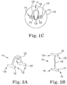
- the anchor or fastener may be any known or future-developed structure useful to connect to such tissue, including but not limited to an "H"-style or "I”-style plastic soft tissue anchors as shown herein, such as at figure 2B and other figures.
- Examples of systems, devices, tools, implants, etc., described herein can be useful in medical or surgical instruments, assemblies, implantable supportive implants, systems, and related methods for treating a pelvic condition including prolapse (e.g., any form of vaginal prolapse), urinary incontinence, fecal incontinence, levator defects, etc., in a male or female patient, and hernias.
- An implant can be implanted in a male or a female to treat a condition such as prolapse, urge incontinence, mixed incontinence, overflow incontinence, functional incontinence, hernia, and the like.
- An implant can include a tissue support portion (or “support portion”) that can be used to support a urethra (including a bladder neck), bladder, vaginal tissue (e.g., vaginal apex), levator, rectum, sphincter, abdominal muscle, or other pelvic tissue (these tissues referred to generally as “supported tissue”).
- a tissue support portion or “support portion” that can be used to support a urethra (including a bladder neck), bladder, vaginal tissue (e.g., vaginal apex), levator, rectum, sphincter, abdominal muscle, or other pelvic tissue (these tissues referred to generally as “supported tissue”).
- Supporting a "urethra” refers to supporting tissue that includes the urethra (which can refer to the bladder neck), and that can optionally include tissue adjacent to a urethra such as bulbospongiosus muscle, corpus spongiosum, or both.
- An implant can additionally include one or more extension portion (otherwise known as an "end” portion or “arm”) attached or attachable to the tissue support portion.
- an implant can include two or four extension portions.
- Extension portions are elongate pieces of material (e.g., mesh, molded implant material, suture, or biologic material) that extend from the tissue support portion and either are or can be connected to the tissue support portion, and are useful to attach to anatomical features or "supportive tissue" in the pelvic region (e.g., using an anchor or fastener) to thereby provide support for the tissue support portion and the supported tissue.
- two extension portions can extend from opposite ends of a tissue support portion as elongate "ends," “arms,” or “extensions,” and may attach to supportive tissue in the pelvic region by extending through a tissue path to an internal anchoring point (see, e.g., Applicant's co-pending application having U.S. Publication No. 2010/256442, filed August 8, 2008, by Ogdahl , entitled SURGICAL ARTICLES AND METHODS FOR TREATING PELVIC CONDITIONS. Also see U.S. Publication No. 2011/0034759 and International Patent Publication Nos. WO 2010/093421 , WO 2011/063412 , and WO 2011/072148 .
- Soft tissue anchors, systems, and method as described herein can be useful with any of these and similar surgical implants and methods, e.g., by which a soft tissue anchor as described is used to securing an extension portion of an implant at a location to secure the implant to tissue, e.g., at supportive tissue.
- each extension portion can extend from the location of attachment with the tissue support portion, through pelvic tissue or space, and optionally be attached to supportive tissue within the pelvic region.
- the supportive tissue can be tissue adjacent to the urethra such as pelvic fascia; tissue between the urethra and an obturator foramen such as pelvic fascia; or tissue of an obturator foramen such as obturator fascia, obturator internus muscle, obturator membrane, obturator externus muscle, etc.
- Other supportive tissue for different procedures include a ligament, tendon, or muscle in the pelvic region such as an arcus tendineus, sacrospinous ligament, abdominal muscle (e.g., for hernia repair), or levator muscle, or tissue of a region of a sacrum such as an anterior longitudinal ligament.
- a ligament, tendon, or muscle in the pelvic region such as an arcus tendineus, sacrospinous ligament, abdominal muscle (e.g., for hernia repair), or levator muscle, or tissue of a region of a sacrum such as an anterior longitudinal ligament.
- An implant may include portions, pieces, or sections that are synthetic or of biologic material (e.g., porcine, cadaveric, etc.). Extension portions may be, e.g., a synthetic mesh such as a polypropylene mesh, a suture, a molded implant material, or the like.
- the tissue support portion may be synthetic (e.g., a polypropylene mesh or a molded material) or biologic.
- implant products that may be similar to those useful according to the present description include those sold commercially by American Medical Systems, Inc., of Minnetonka MN, under the trade names Apogee®, Perigee®, and Elevate® for use in treating pelvic prolapse (including vaginal vault prolapse, cystocele, enterocele, etc.), and Sparc®, Bioarc®, Monarc®, MiniArc®, InVanceTM, and AdVanceTM for treating urinary incontinence.
- Apogee® Perigee®
- Elevate® for use in treating pelvic prolapse (including vaginal vault prolapse, cystocele, enterocele, etc.)
- Sparc® Bioarc®, Monarc®, MiniArc®, InVanceTM, and AdVanceTM for treating urinary incontinence.
- Pelvic implant installation procedures may be performed through an abdominal opening (by open abdominal surgery), laparoscopically (e.g., through a laparoscopic incision in an abdomen), transvaginally in a female patient, or through a medial (perineal) incision in a male patient.
- a soft tissue anchor delivery device can be used to deliver a soft tissue anchor to a surgical site of a pelvic implant installation procedure, to secure an implant material (e.g., an extension portion of an implant) at the surgical site.
- a soft tissue anchor delivery device can be used in the described methods in a minimally invasive transvaginal SCP procedure, in a laparoscopic SCP procedure, or in an abdominal SCP procedure that involves an open (non-laparoscopic) abdominal incision.
- a soft tissue anchor delivery device can be used in a transvaginal, laparoscopic, or abdominal procedure for treating other conditions such as female vaginal prolapse (cystocele, enterocele, rectocele), male or female urinary or fecal incontinence, a hernia, or a condition of levator tissue (e.g., prolapsed or damaged levator tissue).
- a soft tissue anchor delivery device can be useful for accessing and delivering a soft tissue anchor to a surgical location in a male or female pelvic anatomy during a transvaginal (in female patients), perineal (in a male), laparoscopic, open surgical, or trans-abdominal pelvic procedure, for example to access tissue of the posterior pelvic region such as to perform an SCP procedure, to perform repair of a hernia, or to treat another pelvic condition.
- the soft tissue anchor will also attach to an implant material, securing the implant material at a location of the soft tissue anchor and adjacent tissue.
- the soft tissue anchor can be of a type sometimes referred to herein as a sutureless anchor or a plastic fastener, which is different from fasteners generally referred to as a suture, a knot, or a staple; soft tissue anchors of the type referred to as sutureless anchors or plastic fasteners can be plastic anchors that include two legs and a tie, the two legs being connected by the tie; each of the two legs and the tie is elongate and has a length, and the tie has two ends. A first end of the tie connects to one of the legs, e.g., along a length of the leg, and the second end connects to the other (second) leg, e.g., along a length of the other (second) leg.
- Exemplary anchors can be in the form of an "H" or "I” but other forms are also useful, such as a form wherein the tie is bent or curved.
- the soft tissue anchor can be of any useful dimension.
- the two ends and the tie work together to engage tissue and an implant to secure the implant at a therapeutic or otherwise desired location of the tissue.
- one leg is placed below tissue, the second leg is placed above tissue, and an implant is held against tissue by the second leg (see figure 6 ).
- one leg is placed below tissue, the second leg is also placed below tissue, and the tie extends between the first leg and the second leg passing out of the tissue and passing through an implant such that the tie engages and holds the implant against the tissue (see figure 3A ).
- one leg is placed above tissue, the second leg is also placed above the tissue, and the tie extends between the first leg and the second leg passing below the surface of and through the mass of the tissue such that the tie engages and holds the tissue and the first and second legs hold the implant against the tissue (see figure 3B ).
- the soft tissue anchor can be prepared from any useful material, for example a useful biocompatible polymer, which may either be bioresorbable or non-bioresorbable.
- a useful biocompatible polymer which may either be bioresorbable or non-bioresorbable.
- the soft tissue anchor can preferably be made of a material that is sufficiently flexible and resilient to not become substantially permanently deformed upon being ejected from a distal end of a soft tissue anchor dispensing device, or upon being otherwise manipulated or handled during uses described herein.
- useful materials include flexible plastics such as polyethylene, polypropylene, and other thermoplastic or thermoformable materials, as well other types of biocompatible and optionally bioabsorbable or bioresorbable materials.
- Exemplary bioabsorbable materials include, e.g., polyglycolic acid (PGA), polylactide (PLA), copolymers of PGA and PLA.
- the soft tissue anchor and its constituent legs and tie can be of any dimensions useful to allow use of the soft tissue anchor according to a medical use or a surgical use to connect tissue to tissue or to connect tissue to an implant, such as by a transvaginal, laparoscopic, or open surgical method.
- the overall size of the soft tissue anchor can be such that the soft tissue anchor can be inserted through a transvaginal, laparoscopic, or open surgical incision.
- the soft tissue anchor For a laparoscopic incision, the soft tissue anchor must be sufficiently small to be inserted through a laparoscopic cannula and a small incision, as are used in laparoscopic techniques.
- Preferred soft tissue anchors may be flexible to allow improved ease of placement through a surgical incision or laparoscopic cannula.
- first and second legs and the tie may also be as required to function in the manner described herein, e.g., to secure a surgical implant to tissue.
- a leg can have a length that will be sufficient to secure the leg within tissue, if placed in tissue (see figures 3A and 6 ).
- a leg can have a length that will be sufficient to retain an implant material at a location along the length of the tie, such as to keep the implant material located adjacent to and external to tissue if a first leg of the soft tissue anchor, or a tie of the soft tissue anchor, is placed under the tissue and the second leg (and optionally a first leg) is passed through an implant material (see figures 3B and 6 ).
- a tie that connects one leg to the second leg should be of a sufficient length to allow the tie to secure an implant material to tissue with one or two legs of the soft tissue anchor placed within tissue of a patient (see figures 3A and 6 ), or with both legs above the tissue (see figure 3B ).
- a leg of a soft tissue anchor can be of a length in a range from about 2.540 mm (0.10 inch) to about 25.40 mm (1 inch), such as from 3.81 mm (0.15 inch) to 19.05 mm (0.75 inch).
- a length of one leg of a soft tissue anchor may be the same as or different from a length of a second leg of the same soft tissue anchor.
- a length of a tie of a soft tissue anchor can be of a length in a range from about 2.540 mm (0.1 inch) to about 25.40 mm (1 inch), such as from 3.81 mm (0.15 inch) to 19.05 mm (0.75 inch).
- Each of the tie and legs can exhibit a cross section that is preferably solid, and that can be of any form, such as a circular, square, rectangular, triangular, oval, or otherwise shaped cross section.
- a width dimension of the cross section (e.g., diameter) of each of the legs and tie can be as desired, with examples of a cross-sectional dimension being from about 0.254 mm to about 2.54 mm (0.01 to about 0.1 inch), e.g., from 0.381 to 2.032 mm (0.015 to 0.08 inch).
- tissue fastener 114 includes leg 124, second leg 125, and tie 126.
- Tie 126 is shown to be biased to include a curve.
- Each of legs 124 and 125 includes a distal end 130, a proximal end 132, and a length therebetween; ends of tie 126 connect to legs 124 and 125 at a position along a length of each leg, e.g., at a medial location as illustrated.
- a length of each of legs 124 and 125 can be as described, for example in a range from about 5.08 to about 7.62 mm (from about 0.2 to about 0.3 inch) (other ranges will also be useful, depending on the application); a length of tie 116, between legs 124 and 125, can be as described, for example in a range from about 7.112 to about 8.128 mm (0.28 to about 0.32 inch) (other ranges also being useful for various applications).
- a soft tissue anchor delivery device includes a proximal end with a handle, and an elongate shaft for reaching and accessing tissue at a surgical site through a surgical incision.
- the shaft can have a length to allow access and delivery of a soft tissue anchor to a desired surgical site, when the elongate shaft is placed transabdominally, laparoscopically, or transvaginally, or at an open surgical site, e.g., a length to allow a distal end of the device to reach desired tissue while the shaft of the device extends through an abdominal, laparoscopic, vaginal, or other another surgical incision, and the proximal end and optional handle are located externally to the patient.
- a proximal end and optional handle of a soft tissue anchor delivery device remain external to the patient during use to allow a surgeon or other user to access and manipulate the proximal end, to thereby place and control the distal end at a surgical site.
- a soft tissue anchor can be located and held at the distal end, and can be placed as desired at tissue of a surgical site, then ejected into the tissue by manipulation of the proximal end.
- Exemplary lengths of a shaft of a soft tissue anchor delivery device useful for treating a pelvic condition may be in a range from 10 to 22 centimeters, e.g., from 13 to 20 centimeters, especially for use in a female patient to laparoscopically or transvaginally access a posterior location of a pelvic region such as a region of sacral anatomy.
- Exemplary diameters of a shaft of a soft tissue anchor delivery device may be suitable to pass through a surgical incision, e.g., laparoscopically through a laparoscopic cannula or a laparoscopic trocar.
- Exemplary diameters can be in a range from 0.125 mm (1/8 inch) to 25.4 mm (1 inch), e.g., from 0.125 mm (1/8 inch) to 19.05 mm (3 ⁇ 4 inch), or from 0.125 mm (1/8 inch) to 12.7 mm (1 ⁇ 2 inch).
- Other lengths and diameters may be useful for different uses of the device; a shorter shaft may be useful for working on tissue that is more easily accessed or closer to a surgical opening of a patient; larger diameters may be useful for applications that are not laparoscopic, or for applications that involve a soft tissue anchor of larger dimensions.
- the shaft e.g., at a distal end or distal region of the length, can include a lengthwise magazine or equivalent space or holding area capable of containing one or more soft tissue anchor.
- the magazine or the device in general is also preferably capable of advancing one or a series of multiple connected or unconnected soft tissue anchors in a distal direction, e.g., from a proximal position along a length of the shaft to a more distal position along the length of the shaft.
- the magazine can be in communication with one or more additional spaces designated and useful to hold a soft tissue anchor, stage a soft tissue anchor, or eject a soft tissue anchor from a tip of the distal end and into soft tissue.
- the handle, shaft, and shaft distal end can also include one or more locations and mechanisms (e.g., internally) that can be controlled from the proximal end, to manipulate one or a series of soft tissue anchors in a magazine or other position in the shaft, to advance a soft tissue anchor distally or to eject a soft tissue anchor from a tip of the shaft.
- the device e.g., handle or shaft
- the device may include an advancing mechanism that can be actuated from the proximal end to advance a soft tissue anchor (or series of anchors) in a distal direction within the magazine.
- the shaft may include a staging mechanism (that may be the same as or different from the advancing mechanism) that can be actuated from the proximal end to transfer a single soft tissue anchor from a position in the magazine to a staging position.
- the shaft may include an ejecting mechanism that can be actuated from the proximal end to eject a soft tissue anchor, or a portion thereof, from a tip of the shaft in a manner that can insert the soft tissue anchor (or a portion thereof) into soft tissue such as supportive tissue or supported tissue, such as through a sharpened hollow needle.
- Figures included herewith show exemplary embodiments of soft tissue anchor delivery devices (sometimes merely “devices” for short, herein).
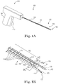
- Figure 1A shows device 100 having proximal end 102, distal end 104, and shaft 110 extending therebetween.
- Handle 108 is located at proximal end 102 and includes actuator (e.g., trigger) 112.
- Distal end 104 also a distal end of shaft 110 includes longitudinal (lengthwise) magazine 116 extending along a length of shaft 110.
- the device can allow manipulation of a soft tissue anchor by steps of advancing the anchor distally within the magazine, transferring a single anchor from the magazine to a staging location distal to the magazine, and ejecting the anchor from the staging location into tissue, e.g., through a sharpened hollow needle.
- magazine 116 can hold and maintain one or a series of soft tissue anchors (also: “fasteners” or “plastic fasteners”) 114 longitudinally along a length of shaft 110. Magazine 116 may optionally be structured to contain each anchor 114 completely within shaft 110, and to engage both of legs 124, 125 within parallel magazine channels 136.
- An outer cover or cowling e.g., cylindrical cover 111 can be present on an outer surface of shaft 110 to at least partially close the interior of shaft 110 and prevent any portion of anchors 114 (e.g., a leg 124, 125, or tie 126) from extending loosely away from shaft 110; this can prevent contact between tissue and a portion of an anchor during use of device 100.
- Tip (or "distal end tip") 106 includes one or more aperture 120 capable of ejecting soft tissue anchor 114 or a portion thereof such as a leg (124, 125) from tip 106 and into tissue.
- Aperture 120 is a distal end of an opening that extends longitudinally along a length of shaft 110 in a proximal direction, and is defined by needle 115.
- tip 106 can also include a sharpened needle end 122, which includes aperture 120 in the form of an internal channel 120 (extending into needle 115) through which a portion of soft tissue anchor 114 (e.g., such as leg 124, 125) can be passed, and from which the portion of soft tissue anchor 114 can be ejected to enter (and optionally pass through) tissue, with needle 115 being inserted into the tissue or through the tissue.
- Tip 106 includes two sharpened needle ends 122, each including aperture 120, and each of which can be placed through an implant material (of a first tissue) and then within tissue (not shown) (e.g., a first tissue or a second tissue), together.
- legs 124 and 125 of soft tissue anchor 114 can be passed through each of the two apertures 120, to be inserted into the tissue, while also being passed through material of an implant or a second tissue.
- a result can be as shown at figure 3A : an implant 127 (alternately tissue) held to tissue 129 by fastener 114, with two legs (124 and 125) being located below tissue 129 and tie 126 extending between the legs and also through implant 127 to hold implant 127 against tissue 129.
- device 100 includes proximal end handle 108, which contains mechanisms that allow for indexing, staging, and ejection of soft tissue anchor 114, leg 124, leg 125, or both legs 124 and 125 from tip 106.
- the mechanism can include, for example, a trigger and one or more pushrod (not shown) extending along shaft 110 through a length of needle 115, which can be moved distally to push a leg 124, 125, distally out of an aperture 120; a mechanism can optionally include two such pushrods, one each for independently ejecting leg 124 and leg 125 from respective apertures 120 of needles 115, simultaneously or separately.
- needle or needles 115 can be placed through implant material (e.g., an extension portion of an implant) or a tissue, and also can be placed to penetrate tissue (e.g., a second tissue) at a surgical location; legs 124, 125 can be advanced along the length of shaft 110 to staging area 140
- An actuator e.g., trigger 112 at handle 108 can be moved to advance the one or more pushrods to move legs 124 and 125 distally through apertures 120, to eject legs 124 and 125 into tissue.
- a single movement or "stroke" of trigger 112 can be sufficient to pass leg or legs 124, 125 from distal end 106 and and into tissue.
- FIG. 1B is a more detailed illustration of distal end 104 of figure 1A .
- Figure 1C is an end view of a cross section of shaft 110.
- magazine 116 of device 100 can support and hold a series of connected or unconnected "H"-type soft tissue anchors 114.
- Each soft tissue anchor 114 includes two legs 124, 125, situated in parallel with lengths of legs 124, 125 extending parallel to a longitudinal axis and length of shaft 110. Legs 124, 125 of each soft tissue anchor 114 are connected by tie 126.
- Each leg 124, 125 of soft tissue anchor 114 can be considered to include a distal end 130 and a proximal end 132.
- these distal and proximal ends 130 and 132 may be equivalent, e.g., in length and form.
- Shaft 110 as illustrated includes two parallel magazine channels 136 running lengthwise along shaft 110 and in communication with or as part of magazine 116. As shown at figure 1B , each of legs 124, 125 can be inserted into one of parallel magazine channels 136. At rest, tie 126 of anchor 114 can optionally be biased to be straight or arched (e.g., bent) (see figures 2B and 2A , respectively). A series of connected or unconnected anchors 114 can be placed into magazine 116 (see figure 1B ) by loading each of the two legs 124, 125 into a proximal end opening (not shown) of the two parallel magazine channels 136.
- Each anchor or the series of anchors can be advance distally along a length of magazine 116 by an advancing mechanism (not shown) such as one or more pushrod within one or more of magazine channels 136.
- an advancing mechanism such as one or more pushrod within one or more of magazine channels 136.
- staging position 140 Located at the distal end of magazine channels 136 is staging position 140, which includes two staging spaces 142a and 142b along a length of shaft 110, each in communication with one of magazine channels 136 and at a location distal to the ends of channels 136 but on a proximal side of sharpened ends 122 of needles 115. Measured laterally from a longitudinal axis or center of shaft 110, the location of each staging space 142a, 142b, is farther away from (farther "outboard" of) the longitudinal axis of shaft 110, than are the locations of each of magazine channels 136; accordingly, the distance between each of staging spaces 142a and 142b is greater than the distance between the two magazine channels 136, as illustrated.
- Each staging space 142a, 142b is sized to accept a leg 124 or 125 of an anchor 114, e.g., has a length that is at least equal and preferably slightly greater than a length of each of legs 124 and 125, and is aligned with an aperture 120 of a needle 115 to allow ejection from tip 106 in a distal direction.
- a magazine pushrod in one or both of magazine channels 136, or another type of advancing mechanism at a location of shaft 110 or handle 108, can be actuated to move in a distal direction to engage a proximal end 132 of leg or legs 124, 125 of anchor 114, or a proximal end of a proximal anchor of a series of anchors 114 held in magazine channels 136, or a proximal end of a strip that includes a series of anchors 114.
- the magazine pushrod or the other advancing mechanism can be used to push an anchor 114 or series of anchors 114 in a distal direction.
- legs 124, 125 of a distal-most anchor 114 are expelled from magazine channels 136 and are received into staging spaces 140a and 142b to rest within a needle channel of needles 115, the needle being aligned with apertures 120. Because the distance between each of staging spaces 142a and 142b is greater than the distance between the two magazine channels 136, legs 124 and 125 spring laterally into spaces 142a and 142b, as strain on tie 126 is partially released. See figure 1B . See also figure 1C , which shows legs 124 and 125 located within channels 136 before being released into spaces 142a and 142b; the locations of spaces 142a and 142b are aligned with apertures 120 as illustrated at figure 1C .
- an ejection pushrod located in one or both of needle channels of needles 115, e.g., extending along shaft 110 between handle 108 and distal end 104, can be moved distally to engage a proximal end 132 of one or both of legs 124, 125 located within staging spaces 142a, 142b.
- the ejection pushrod or pushrods can push one or both of legs 124, 125, through apertures 120 to eject legs 124, 125 out of sharpened needle ends 122 and into tissue, through implant material, or through implant material and into tissue, or through multiple tissues; the ejection causes two ends of tie 126 (each end connected to a leg 124, 125) to pass through both the tissue, implant material, etc., also causing a center length of tie 126 to remain external to the tissue and to engage and hold the implant material (or tissue) against the tissue (see figure 3A ).
- a single movement or "stroke" of trigger 112 can be sufficient to pass leg or legs 124, 125, from a location at a distal end of magazine channels 136, distally to become located at staging spaces 142a, 142b, and also to cause one or two ejection pushrods to move distally to then push leg or legs 124, 125 further distally to eject leg or legs 124, 125 from the ends of needles 115 and into tissue.
- FIG 3A shows an exemplary configuration of anchor 114 after ejection from device 100 of figures 1A-1C , having two parallel needles 115.
- each of legs 124 and 125 have been ejected from distal end 106 of device 100, passed through implant material 127, and then into or optionally through tissue 129, to become secured by or within tissue 129.
- Each of two ends of tie 126 extend through tissue 129 and also through implant material 127, to secure implant material 127 to tissue 129.
- Tissue 129 may be any tissue, e.g., tissue of a pelvic region, such as a supportive tissue.
- Implant material 127 may be any implant material that is part of any type of implant, such as an extension portion of an implant. Implant material 127 as illustrated is designated to be an implant material, but this material may alternately represent a second tissue, attached by anchor 114 to the first tissue 129.
- the tissue anchor may be situated differently relative to a tissue, an optional implant material, and an optional second tissue, for example as shown at figure 3B and at figure 6 .
- implant 127 (alternately tissue) is held to tissue 129 by fastener 114, with two legs (124 and 125) being located above tissue 129 and implant (or tissue) 127, and tie 126 extending between the two legs and also through tissue 129 to hold implant 127 (alternately tissue) against tissue 129.
- Figure 4 shows another example of a soft tissue anchor delivery device 100, which includes certain features and structure that are similar to device 100 of figure 1A , specifically including proximal end 102, distal end 104, shaft 110 extending therebetween, handle 108, actuator (e.g., trigger) 112, and longitudinal (lengthwise) magazine 116 extending along a length of shaft 110.
- Device 100 of figure 4 differs from device 100 of figure 1A by way of various structural differences relating to magazine 116 and mechanisms for advancing, staging, and ejecting an anchor 114 from distal end 106.
- device 100 of figure 4 includes a long (e.g., extruded metal or plastic) shaft 110 containing magazine 116, which in turn can contain a collated strip of molded polymeric (plastic) fasteners 114.
- the device can allow manipulation of an anchor by steps of advancing the anchor distally within the magazine, transferring a single anchor from the magazine to a first staging location, transferring the single anchor from the first staging location to a second staging location (which is also referred to as the "ejecting location"), and ejecting the anchor from the second staging location, into tissue.
- a rotating tip (or disc 160, which is capable of rotating about an axis aligned with or coinciding with a longitudinal axis of shaft 110) situated at the distal end of the magazine can accept a tissue fastener from the collated strip, and can rotate to shear the distal-most or terminal fastener 114 off of the strip; rotating tip (or disc 160), when rotated, aligns one leg (124) of that fastener 114 (the cross-section thereof) with aperture 120 of needle 115.
- Needle 115 is structurally built into an optional end cap (170) that covers rotating disc 160.
- a needle e.g., 115
- a needle can be located at any other useful location, such as by being directly incorporated into rotating disc 160, in which case cap 170 may be eliminated.
- Rotating disc 160 is driven by a rotating staging shaft (123 at figures 8C , 9 , 10 ) extending along a length of shaft 110, e.g., from proximal end 102 to distal end 104, including along the length of magazine 116.
- a pin or molded feature 166 provides a stop to ensure correct alignment of rotating disc 160 at both limits of its rotation.
- a leg of the terminal fastener 114 can be ejected through aperture 120 of hollow needle 115 by a push rod (e.g., ejection push rod 121 at figures 5C , 8C , 9 , 10 ) also extending along the length of shaft 110, e.g., from proximal end 102 to distal end 104, including along a length of magazine 116.
- a push rod e.g., ejection push rod 121 at figures 5C , 8C , 9 , 10
- a push rod also extending along the length of shaft 110, e.g., from proximal end 102 to distal end 104, including along a length of magazine 116.
- the actuation mechanism for causing rotation of rotating staging shaft 132, and distal movement of ejection pushrod 121, as well as an indexing mechanism for the collated strip, are located at proximal end 102, e.g., within handle 108, and can be operated by movement of trigger 112; preferably a single stroke of trigger 112 is effective to actuate all three of the indexing mechanism (to advance an anchor 114 along a length of shaft 110), the rotating staging shaft 123 (to stage a distal-most fastener 114), and the ejection pushrod (to eject a staged fastener 114 distally from sharpened tip 122 of needle 115).
- distal end 104 includes features that include shaft 110 and magazine 116.
- a series of fasteners 114 resides in magazine 116 with each of legs 124, 125 held in one of two parallel magazine channels 136 extending internally and longitudinally along a length of shaft 110; ties 126 extend laterally between legs 124, 125 and channels 136.
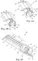
- Figure 5A shows distal end 104 exclusive of end cap 170 (which is optional) and needle 115 (which may alternately be located at rotating disc 160), to better illustrate features of rotating (staging) disc 160 with a fastener 114 loaded (staged) within disc 160; disc 160 is situated in a non-rotated position or a "staging" position. Fastener 114 is located within staging slot 162 of disc 160.
- Figure 5B also shows distal end 104 exclusive of end cap 170 and needle 115; at figure 5B , disc 160 has been rotated (counterclockwise from the perspective of the viewer of figure 5B ) into a deployment or "ejection" position.
- terminal fastener 114 has been sheared off of the strip or series of (e.g., connected) fasteners 114 located and positioned end-to-end (of legs 124, 125) along a length of magazine 116; leg 124 has been rotated and is now aligned with a position of needle 115 (not shown). Legs 124 and 125, and tie 126, all are located within staging slot 162 of disc 160.
- Figure 5C shows distal end 104 including optional cap 170, and shows rotating disc 160 in the ejection position also illustrated at figure 5B .
- End cap 170 is stationary at the end of shaft 110. Needle 115 of stationary end cap 170 is aligned with ejection push rod 121 extending along shaft 110; curved slot 172 of end cap 170 aligns with curved slot 162 of rotating (staging) disc 160 when disc 160 is rotated to the "ejection" position of figure 5B .
- distal end 104 of figures 5A, 5B, and 5C includes a staging mechanism in the form of rotating (staging) disc 160.
- a distal-most anchor 114 becomes located within curved slot 162 of rotating (staging) disc 160.
- legs 124, 125 of anchors 114 are contained at two ends of curved slot 162, with distal ends 130 of legs 124, 125 passing first into slot 162.
- Tie 126 is also within slot 162.
- the lengthwise dimension (along the longitudinal axis of shaft 110) of disc 160 and slot 162 is about the same dimension as the lengthwise dimension (along the longitudinal axis of shaft 110) of each of legs 124, 125.
- Tip 106 includes a single longitudinal channel or aperture 120 capable of ejecting a single leg 124 of soft tissue anchor 114 into tissue.
- Aperture 120 extends through needle 115 and sharpened needle end 122, which extends in a proximal direction and is in communication with channel 119 extending longitudinally along a length of shaft 110.
- Channel 119 also includes ejection pushrod 121, which can be actuated to move distally to push leg 124 and eject leg 124 through aperture 120 of needle 115.
- Optional end cap 170 includes curved slot 172, which aligns with slot 162 of disc 160, with disc 160 in the deployment (ejection) position (also considered a "second staging position"). Slot 172 is stationary and is sized to allow passage of anchor 114.
- Device 100 also includes a staging mechanism including staging shaft 123 that connects to rotating (staging) disc 160, to rotate disc 160 between a non-deployed position (staging position, shown at figure 5A ) and a deployed position (ejection position, or second stating position, shown at figure 5B ).
- staging position e.g., at handle 108 or shaft 110
- disc 160 can be rotated. Rotation of disc 160 moves anchor 114 contained in slot 162 rotationally, to a second staging position for ejection.
- multiple anchors 114 of a series of anchors in magazine 116 are connected at ends of legs 124, 125 (a distal end of a proximal anchor 114 is connected to a proximal end of an adjacent anchor 114). Rotation of disc 160 will also break off the distal-most anchor 114 from the series, i.e., the anchor held within slot 162, from the adjacent, next proximal anchor.
- ejection pushrod 121 can be moved distally to contact a proximal end 132 of the leg 124, 125 of anchor 114 that is aligned with channel 119 and aperture 120 of sharpened needle 115.
- Ejection pushrod 121 can be advanced distally to push first leg 124 (leading leg or ejected leg) through aperture 120 and into tissue; the rest of anchor 114, i.e., tie 126 and second (following) leg 125, passes through slot 172 of end cap 170, optionally through an implant, and into tissue.
- Ejected leg 124 enters tissue; tie 126 extends from ejected leg 124 to a location external to the tissue and can optionally pass through an implant material or another tissue; the second leg 125 is located on a proximal side of the optional implant material or second tissue, on a side of the opposite of the first tissue, and the implant material or tissue through which tie 126 passes is secured to the tissue by second leg 125 (see, e.g., figure 6 ).
- anchors 114 are loaded into magazine 116.
- An advancing mechanism advances an anchor 114 or a distal-most anchor 114 through magazine 116 and into slot 162.
- Disc 160 is rotated by actuation of and rotation of staging shaft or cam 123 (see figures 5C and 8C ), causing rotating disc 160 to rotate from a non-deployed (staging or first) position ( figure 5A ) to a deployed position (or second staging position, figure 5B ) in which anchor 114 located in slot 162 is in an ejection position.
- ejecting pushrod 121 can be actuated and moved distally to contact a proximal end 132 of a first leg 124 of anchor 114, located in slot 162 and aligned with aperture 120 of sharpened needle 115.
- Sharpened needle 115 can be passed through an implant material and tissue, or tissue and tissue.
- Ejection pushrod 119 then is advanced distally to push first leg 124 through aperture 120 of sharpened needle 122, through the implant material and into the tissue, optional implant, etc.
- Tie 126 and a second leg 125 of anchor 114 is carried out of slot 162, passes through slot 172, and holds tissue or implant material against the tissue.
- Figure 6 shows an example of anchor 114 after ejection from device 100 of figure 4 and 5A, 5B, and 5C , having a single needle 115 for ejecting a single leg of anchor 114 into tissue.
- one leg (124) (the "first" leg, or an “ejected” leg) has been passed through tissue 129 to become secured within tissue 129.
- Tie 126 extends through tissue 129 and implant material 127, and the second leg (125) holds implant material 127 against tissue 129.
- Implant material 127 as illustrated is designated to be an implant material, but this material (127) may alternately represent a second tissue attached by anchor 114 to the first tissue 129.
- Figure 7A through 7D show examples of fastener strips ("soft tissue anchor strips") 200 that include proximal end 202, distal end 204, and mid portion 206.
- Proximal end 202 and mid portion 206 can be made of any useful material, such as metal or plastic and in use in device 100 can reside in a longitudinal lumen sized and shaped to receive these portions of strip 200.
- Proximal end 202 includes an indexing feature for engaging an indexing (or "advancing") mechanism of a device 100; the indexing feature (203) may include a set of apertures (e.g., rectangular, square, round, oval, etc.), a set of teeth, or another regularly-repeating surface or structure useful for moving strip 200 distally a regular distance equal to a length of legs 124, 125 of a fastener 114, with each single actuation (stroke or throw) of an actuating mechanism at proximal end 102, such as trigger 112.
- Distal end 204 includes a series of soft tissue anchors 114.
- Each anchor 114 is connected to one or two adjacent anchor or anchors in the series, with proximal ends 132 of legs 124, 125 of each anchor 114 being connected to distal ends 130 of legs 124, 125 of an adjacent (more proximal) anchor in the series.
- the connections 133 between the proximal ends and the distal ends of the adjacent anchors 114 are joints, e.g., frangible joints, or a frangible hinge, that can be made of the same material as fasteners 114, but of reduced size (e.g., diameter and cross section).
- Connections 133 can be broken (e.g., sheared or pulled apart) by a mechanism at a distal end of a shaft 110 of a device 100, such as by an advancing mechanism, by a staging mechanism (e.g., by rotation of disc 106 while a terminal tissue fastener 114 is located in slot 162), or by another mechanism.
- a mechanism at a distal end of a shaft 110 of a device 100 such as by an advancing mechanism, by a staging mechanism (e.g., by rotation of disc 106 while a terminal tissue fastener 114 is located in slot 162), or by another mechanism.
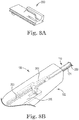
- Figures 8A, 8B , and 8C show certain details of an exemplary actuating mechanisms and related structure in a device 100 (of figure 4 ), capable of advancing a soft tissue anchor 114, staging the soft tissue anchor 114, and ejecting the soft tissue anchor 114 from a distal end of shaft 110 of device 100; preferred mechanisms allow for all three of advancing, staging, and ejecting the soft tissue anchor 114 to occur by a single pull of an actuator such as a trigger (112), lever, or other actuating mechanism.
- an actuator such as a trigger (112), lever, or other actuating mechanism.
- a delivery and indexing cycle can include four steps or phases: 1 - A step to advance fastener strip 200 one unit to move a terminal fastener 114 into slot 162 of rotating tip 160; 2 - A step of rotating disc 160 about a longitudinal axis of disc 160 and shaft 110, to shear a terminal fastener (114) off of a distal end of distal portion 204 of strip 200, and align one leg (124) of the terminal fastener 114 with aperture 120 and push rod 121; 3 - A step of ejecting the terminal fastener 114 through and out hollow needle 114, but distally pushing push rod 121; and 4 - A reset step.
- These operations are all driven by cams on a carriage driven through linkages in the handle, or any other suitable mechanism or combination of mechanisms.
- an inclined plane on carriage 130 causes rocker 301 to rotate forward, and through a pawl, advances index strip 203 of strip 200 precisely the length of one fastener leg (124, 125). This moves the last fastener 114 on strip 200 into slot 162 of rotating tip 160 at the end of shaft 110 (i.e., into a first staging position).
- cam follower 129 on the rotating staging shaft 123 is in a straight segment of the cam profile of carriage 300, so that staging shaft 123 is not caused to rotate.
- leg 124 After ejection of leg 124, spring 309 causes carriage 300 to return to its initial position. Rocker 301 rotates back as it goes back to the bottom of the inclined plane and resets the pawl.
- a transvaginal method to reach a sacral promontory can include:
- Soft tissue anchor delivery devices as described and illustrated can be used and useful by a method of inserting the device into a surgical incision, for example a transvaginal, laparoscopic, or abdominal incision, and manipulating the distal end and distal end tip to a desired surgical location, such as a location of soft supportive tissue.
- a shaft of the soft tissue anchor delivery device can be passed through an incision to place the shaft distal end at a region of sacral anatomy.
- the soft tissue anchor delivery device can be used to secure a portion of a pelvic implant to tissue at the region of sacral anatomy, such as to an anterior longitudinal ligament.
- the method can optionally also involve a tool (e.g., retractor or expansion member), implant, adjustable implant, anchor, or other device or method, e.g., as described at Applicant's co-pending International Patent Application having International Patent Application number PCT/US2010/062577, filed December 30, 2010 , published as WO 2011/082350 .
- a tool e.g., retractor or expansion member
- implant e.g., implant, adjustable implant, anchor, or other device or method, e.g., as described at Applicant's co-pending International Patent Application having International Patent Application number PCT/US2010/062577, filed December 30, 2010 , published as WO 2011/082350 .
- a soft tissue anchor delivery device can be placed at a different anatomical location, depending on the type of repair. Described anchors and tools as described can be useful for still other treatments and procedures, such as general surgery procedures, veterinary procedures for treating animals, and plastic surgery for treating muscle or skin tissues such as at a face, leg, stomach, or abdomen.
- a soft tissue anchor delivery device as described and its components can be made from any suitable material or combination of materials. Examples include materials that are known to be useful with surgical devices and tools, including stainless steel, nitinol, polycarbonate, polypropylene, polyethylene, fluoropolymer, PET, polyurethane, silicone, polysulphone, and ultem.
- Implants their various components, structures, features, materials and methods may have a number of suitable configurations as shown and described in references cited, or as described herein.
- Various methods and tools for introducing, deploying, anchoring and manipulating implants to treat prolapse or another pelvic conditions, as disclosed in the references cited, are envisioned for use with the present invention as well as those methods and tools identified and described herein.
- any of the described tissue anchors or insertion tools can be used for connecting one anatomical tissue (e.g., skin, muscle, or another soft tissue or organ tissue) to a second anatomical tissue, e.g., in a male or a female patient, or for veterinary use, and for any of a large variety of conditions, such as a pelvic condition, non-pelvic condition, or for a general surgical or specialty (e.g., plastic surgery) procedure.
- one anatomical tissue e.g., skin, muscle, or another soft tissue or organ tissue
- a second anatomical tissue e.g., in a male or a female patient, or for veterinary use
- any of a large variety of conditions such as a pelvic condition, non-pelvic condition, or for a general surgical or specialty (e.g., plastic surgery) procedure.
- any of the described tissue anchors or insertion tools can be used for placing any desired pelvic implant in a male or a female patient, or for veterinary use, and for any of a large variety of conditions, such as a pelvic condition, non-pelvic condition, or for a general surgical or specialty (e.g., plastic surgery) procedure.
- the implant can include any structural features useful for such treatment, including any desired size, shape, and optional features such as adjustability and anchoring systems. Any of these features may be previously known, future developed, described herein, or described in documents cited herein, for any particular implant and method.
- the present description relates generally to anchors that can be useful for placing a surgical implant.
- an implant that is secured by any of the anchors described can be useful to treat a pelvic condition in a male or a female patient; as a single and non-limiting example, an implant that includes or uses an anchor as described can be used in a transvaginal or transabdominal SCP procedure to provide support to a vaginal cuff (apex), through an implant that is secured to tissue by the anchor, the anchor being attached at a region of sacral anatomy such as a sacral ligament (e.g., anterior longitudinal ligament, a.k.a. the "anterior ligament” or "longitudinal ligament”).
- a sacral ligament e.g., anterior longitudinal ligament, a.k.a. the "anterior ligament” or "longitudinal ligament”
Landscapes
- Health & Medical Sciences (AREA)
- Surgery (AREA)
- Life Sciences & Earth Sciences (AREA)
- Animal Behavior & Ethology (AREA)
- Public Health (AREA)
- Engineering & Computer Science (AREA)
- Biomedical Technology (AREA)
- Heart & Thoracic Surgery (AREA)
- Medical Informatics (AREA)
- Molecular Biology (AREA)
- Veterinary Medicine (AREA)
- General Health & Medical Sciences (AREA)
- Nuclear Medicine, Radiotherapy & Molecular Imaging (AREA)
- Reproductive Health (AREA)
- Vascular Medicine (AREA)
- Gynecology & Obstetrics (AREA)
- Pregnancy & Childbirth (AREA)
- Pathology (AREA)
- Surgical Instruments (AREA)
- Prostheses (AREA)
Claims (9)
- Weichgewebeanker-Zuführungsvorrichtung (100) kombiniert mit einem Weichgewebeanker (114),
welcher Weichgewebeanker (114) ein erstes längliches Bein (124), ein zweites längliches B ein (125) und ein Verbindungsstück (126), das das erste längliche Bein mit dem zweiten länglichen Bein verbindet, aufweist, wobei das Verbindungsstück ein erstes Verbindungsstückende, das mit dem ersten Bein (124) an einem mittleren Ort verbunden ist, und ein zweites Verbindungsstückende, das mit dem zweiten Bein (125) an einem mittleren Ort des zweiten Beins verbunden ist, aufweist,
wobei die Zuführungsvorrichtung (100) aufweist:ein proximales Ende (102) und ein distales Ende (104), wobei das proximale Ende einen Handgriff (108) aufweist,eine Welle (110), die sich von dem Handgriff zu dem distalen Ende erstreckt und eine Längsachse hat,das distale Ende (104) aufweist:ein Magazin (116), aufweisend einen ersten Magazinkanal (136), der sich entlang einer Länge des distalen Endes (104) erstreckt, und einen zweiten Magazinkanal (136), der sich entlang einer Länge des distalen Endes (104) parallel zu dem ersten Magazinkanal erstreckt, und wobei der Anker (114) konfiguriert ist, um in dem Magazin (116) gehalten zu werden, wobei sich das erste Bein (124) in dem ersten Magazinkanal (136) befindet und das zweite Bein (125) sich in dem zweiten Magazinkanal (136) befindet, undeinen Auffangort auf einer distalen Seite des Magazins (116), der einen ersten Auffangraum (142a) und einen zweiten Auffangraum (142b) aufweist, wobei der Anker konfiguriert ist, an dem Auffangort gehalten zu werden, mit dem ersten Bein (124) in dem ersten Auffangraum (142a) angeordnet und dem zweiten Bein (125) in dem zweiten Auffangraum (142b) angeordnet,
gekennzeichnet durcheine drehbare Auffangscheibe (160) distal von dem Magazin (116), wobei die drehbare Auffangscheibe (150) einen Auffangschlitz (162) als den Auffangort, der den ersten Auffangraum und den zweiten Auffangraum enthält, aufweist, die drehbare Auffangscheibe (160) um eine Achse der Welle (110) zwischen einer ersten Auffangposition und einer zweiten Auffangposition drehbar ist, undeine hohle geschärfte Nadel (115) distal von der Auffangscheibe (116), die sich parallel zu der Längsachse der Welle (110) erstreckt,wobei in der ersten Auffangposition der Schlitz (162) mit dem in dem Magazin (116) gehaltenen Anker (114) ausgerichtet ist und in der zweiten Auffangposition das erste Bein (124) des Ankers (114) mit der geschärften hohlen Nadel (115) ausgerichtet ist; undeinen Ejektor, der an dem Handgriff betätigbar ist, um einen Weichgewebeanker von dem Auffangort in die zweite Auffangposition auszustoßen. - Vorrichtung (100) und Anker (114) nach Anspruch 1, bei denen das erste längliche Bein (124) eine Länge in einem Bereich von etwa 0,1 (2,540 mm) bis etwa 1 (25,40 mm) Zoll hat, das zweite längliche Bein (125) eine Länge in einem Bereich von etwa 0,1 (2,540 mm) bis etwa 1 (25,40 mm) Zoll hat, und das Verbindungsstück (126) eine Länge in einem Bereich von etwa 0,1 (2,540 mm) bis etwa 1 (25,40 mm) Zoll hat.
- Vorrichtung (100) und Anker (114) nach Anspruch 1, bei denen der Anker (114) flexiblen Kunststoff aufweist und der Anker nicht permanent verformt wird, wenn er durch die Weichgewebeanker-Zuführungsvorrichtung ausgestoßen wird.
- Vorrichtung (100) und Anker (114) nach Anspruch 1, bei denen das distale Ende (104) durch eine laparoskopische Kanüle angeordnet werden kann, um sich in einem Bereich von stützendem Gewebe zu befinden.
- Vorrichtung (100) und Anker (114) nach Anspruch 1, bei denen das Magazin (116) in der Lage ist, eine Reihe von Weichgewebeankern (114), die in Längsausrichtung angeordnet sind, zu halten, wobei die Reihe einen distalen Weichgewebeanker und einen proximalen Weichgewebeanker aufweist, mit einem proximalen Ort des distalen Weichgewebeankers in Verbindung mit einem distalen Ort des proximalen Weichgewebeankers.
- Vorrichtung (100) und Anker (114) nach Anspruch 1, bei denen das Magazin (116) in der Lage ist, eine Reihe von Weichgewebeankern (114), die in Längsausrichtung angeordnet sind, zu halten, wobei die Reihe aufweist:einen distalen Weichgewebeanker (114), aufweisend ein erstes längliches Bein (124) und ein zweites längliches Bein (125), die durch ein längliches Verbindungsstück (126) verbunden sind, wobei jedes längliche Bein ein distales Ende und ein proximales Ende aufweist,einen proximalen Weichgewebeanker (114), aufweisend ein erstes längliches Bein (124) und ein zweites längliches Bein (125), die durch ein längliches Verbindungsstück (126) verbunden sind, wobei jedes längliche Bein ein distales Ende und ein proximales Ende aufweist, mit einem proximalen Ende jedes länglichen Beins des distalen Weichgewebeankers in Verbindung mit einem distalen Ende jedes länglichen Beins des proximalen Weichgewebeankers.
- Vorrichtung (100) und Anker (114) nach Anspruch 1, bei denen das distale Ende eine erste hohle geschärfte Nadel (115), die sich parallel zu einer Längsachse der Welle (110) erstreckt, und eine zweite hohle geschärfte Nadel (115), die sich parallel zu der Längsachse der Welle (110) erstreckt, aufweist, wobei die erste geschärfte hohle Nadel (115) ausgestaltet ist, ein erstes Bein (124) des Weichgewebeankers (114) auszustoßen, und die zweite geschärfte hohle Nadel (115) ausgestaltet ist, gleichzeitig ein zweites Bein (126) des Weichgewebeankers (114) auszustoßen.
- Vorrichtung (100) und Anker (114) nach Anspruch 7, bei denender Auffangort distal von dem ersten Magazinkanal (116) und distal von dem zweiten Magazinkanal (116) ist,ein erstes Bein (124) eines Ankers (114), der sich an dem Auffangort befindet, mit der ersten geschärften hohlen Nadel (115) ausgerichtet ist, undeines zweites Bein (126) eines Ankers (114), der sich an dem Auffangort befindet, mit der zweiten geschärften hohlen Nadel (115) ausgerichtet ist.
- Vorrichtung nach einem der vorhergehenden Ansprüche, weiterhin aufweisend einen Stift, der angeordnet ist, einen Anschlag vorzusehen, um eine korrekte Ausrichtung der sich drehenden Scheibe (160) an beiden Grenzen ihrer Drehbewegung sicherzustellen.
Priority Applications (1)
| Application Number | Priority Date | Filing Date | Title |
|---|---|---|---|
| EP19161745.5A EP3520708A3 (de) | 2012-07-24 | 2013-07-23 | Systeme und werkzeuge für den anschluss an gewebe |
Applications Claiming Priority (3)
| Application Number | Priority Date | Filing Date | Title |
|---|---|---|---|
| US201261675050P | 2012-07-24 | 2012-07-24 | |
| US13/832,319 US9649114B2 (en) | 2012-07-24 | 2013-03-15 | Systems, tools, and methods for connecting to tissue |
| PCT/US2013/051563 WO2014018473A1 (en) | 2012-07-24 | 2013-07-23 | Systems, tools, and methods for connecting to tissue |
Related Child Applications (2)
| Application Number | Title | Priority Date | Filing Date |
|---|---|---|---|
| EP19161745.5A Division EP3520708A3 (de) | 2012-07-24 | 2013-07-23 | Systeme und werkzeuge für den anschluss an gewebe |
| EP19161745.5A Division-Into EP3520708A3 (de) | 2012-07-24 | 2013-07-23 | Systeme und werkzeuge für den anschluss an gewebe |
Publications (3)
| Publication Number | Publication Date |
|---|---|
| EP2884903A1 EP2884903A1 (de) | 2015-06-24 |
| EP2884903A4 EP2884903A4 (de) | 2016-09-28 |
| EP2884903B1 true EP2884903B1 (de) | 2019-04-17 |
Family
ID=49995570
Family Applications (2)
| Application Number | Title | Priority Date | Filing Date |
|---|---|---|---|
| EP13823116.2A Not-in-force EP2884903B1 (de) | 2012-07-24 | 2013-07-23 | Systeme und werkzeuge für den anschluss an gewebe |
| EP19161745.5A Withdrawn EP3520708A3 (de) | 2012-07-24 | 2013-07-23 | Systeme und werkzeuge für den anschluss an gewebe |
Family Applications After (1)
| Application Number | Title | Priority Date | Filing Date |
|---|---|---|---|
| EP19161745.5A Withdrawn EP3520708A3 (de) | 2012-07-24 | 2013-07-23 | Systeme und werkzeuge für den anschluss an gewebe |
Country Status (5)
| Country | Link |
|---|---|
| US (2) | US9649114B2 (de) |
| EP (2) | EP2884903B1 (de) |
| AU (1) | AU2013293171B2 (de) |
| CA (1) | CA2879820A1 (de) |
| WO (1) | WO2014018473A1 (de) |
Families Citing this family (18)
| Publication number | Priority date | Publication date | Assignee | Title |
|---|---|---|---|---|
| US9504461B2 (en) | 2005-05-20 | 2016-11-29 | Neotract, Inc. | Anchor delivery system |
| US10195014B2 (en) | 2005-05-20 | 2019-02-05 | Neotract, Inc. | Devices, systems and methods for treating benign prostatic hyperplasia and other conditions |
| US7758594B2 (en) | 2005-05-20 | 2010-07-20 | Neotract, Inc. | Devices, systems and methods for treating benign prostatic hyperplasia and other conditions |
| US10130353B2 (en) | 2012-06-29 | 2018-11-20 | Neotract, Inc. | Flexible system for delivering an anchor |
| US9649114B2 (en) * | 2012-07-24 | 2017-05-16 | Ams Research Corporation | Systems, tools, and methods for connecting to tissue |
| AU2014237186B2 (en) * | 2013-03-15 | 2018-11-01 | Boston Scientific Scimed, Inc. | Systems, tools, and methods for connecting to tissue |
| JP6656227B2 (ja) | 2014-08-26 | 2020-03-04 | スピロックス, インク.Spirox, Inc. | 鼻インプラントと使用システム及び使用方法 |
| EP3298969A1 (de) * | 2016-09-26 | 2018-03-28 | CHU de NICE | Chirurgische nähvorrichtung |
| WO2019126718A1 (en) | 2017-12-23 | 2019-06-27 | Neotract, Inc. | Expandable tissue engagement apparatus and method |
| WO2020096827A1 (en) | 2018-11-07 | 2020-05-14 | Neotract, Inc. | System for delivery of a fiducial marker |
| JP2022506545A (ja) | 2018-11-08 | 2022-01-17 | ネオトラクト インコーポレイテッド | 出血を処置するカテーテル |
| CN120585394A (zh) * | 2019-10-25 | 2025-09-05 | 生物螺栓医疗公司 | 用于结合材料的医疗装置 |
| JP7763754B2 (ja) | 2020-02-21 | 2025-11-04 | テレフレックス ライフ サイエンシズ リミテッド ライアビリティ カンパニー | 器具の配備不良を防止する装置 |
| JP2023536560A (ja) * | 2020-06-30 | 2023-08-28 | フレイヤ ヘルスケア エルエルシー | 腹圧性尿失禁の治療システム及び方法 |
| US12336897B2 (en) | 2020-06-30 | 2025-06-24 | The Brigham And Women's Hospital, Inc. | Systems and methods for treating stress urinary incontinence |
| WO2022031455A1 (en) | 2020-08-03 | 2022-02-10 | Teleflex Life Sciences Limited | Handle and cartridge system for medical interventions |
| US12178424B2 (en) * | 2021-02-04 | 2024-12-31 | Aurora Medical Technologies Corp | Suturing breakaway anchor strip |
| US11826041B2 (en) * | 2021-02-12 | 2023-11-28 | Washington University | Barbed rod for linear tissue closure and approximation |
Family Cites Families (82)
| Publication number | Priority date | Publication date | Assignee | Title |
|---|---|---|---|---|
| US2738790A (en) | 1954-08-12 | 1956-03-20 | George P Pilling & Son Company | Suturing instrument |
| US3875648A (en) * | 1973-04-04 | 1975-04-08 | Dennison Mfg Co | Fastener attachment apparatus and method |
| US3948128A (en) | 1973-12-07 | 1976-04-06 | Dennison Manufacturing Company | Feed and severing apparatus |
| US4621639A (en) * | 1982-02-03 | 1986-11-11 | Ethicon, Inc | Surgical instrument with hydraulic actuator |
| US4724840A (en) * | 1982-02-03 | 1988-02-16 | Ethicon, Inc. | Surgical fastener applier with rotatable front housing and laterally extending curved needle for guiding a flexible pusher |
| US4586502A (en) * | 1982-02-03 | 1986-05-06 | Ethicon, Inc. | Surgical instrument actuator with non-collinear hydraulic pistons |
| US4471781A (en) * | 1982-02-03 | 1984-09-18 | Ethicon, Inc. | Surgical instrument with rotatable front housing and latch mechanism |
| US4548202A (en) | 1983-06-20 | 1985-10-22 | Ethicon, Inc. | Mesh tissue fasteners |
| US4873976A (en) | 1984-02-28 | 1989-10-17 | Schreiber Saul N | Surgical fasteners and method |
| US4696300A (en) * | 1985-04-11 | 1987-09-29 | Dennison Manufacturing Company | Fastener for joining materials |
| US4848637A (en) * | 1987-06-11 | 1989-07-18 | Pruitt J Crayton | Staple device for use on the mesenteries of the abdomen |
| EP0437481B1 (de) | 1988-10-04 | 1995-03-15 | PETROS Peter Emmanuel | Chirurgisches instrument, prothese |
| US5020713A (en) * | 1989-05-04 | 1991-06-04 | Kunreuther Steven J | Assembly of attachments and device for attaching same |
| USRE34857E (en) * | 1989-05-04 | 1995-02-14 | Kunreuther; Steven J. | Assembly of attachments and device for attaching same |
| US4932962A (en) | 1989-05-16 | 1990-06-12 | Inbae Yoon | Suture devices particularly useful in endoscopic surgery and methods of suturing |
| GB8924806D0 (en) | 1989-11-03 | 1989-12-20 | Neoligaments Ltd | Prosthectic ligament system |
| US5085661A (en) | 1990-10-29 | 1992-02-04 | Gerald Moss | Surgical fastener implantation device |
| US5203864A (en) | 1991-04-05 | 1993-04-20 | Phillips Edward H | Surgical fastener system |
| CA2065205C (en) * | 1991-04-11 | 2002-12-03 | David T. Green | Reduced mass absorbable surgical fastener and retainer |
| ATE163528T1 (de) | 1991-12-03 | 1998-03-15 | Boston Scient Ireland Ltd | Implantationsvorrichtung für einen knochenanker |
| US5439467A (en) | 1991-12-03 | 1995-08-08 | Vesica Medical, Inc. | Suture passer |
| US6048351A (en) | 1992-09-04 | 2000-04-11 | Scimed Life Systems, Inc. | Transvaginal suturing system |
| US5381943A (en) * | 1992-10-09 | 1995-01-17 | Ethicon, Inc. | Endoscopic surgical stapling instrument with pivotable and rotatable staple cartridge |
| US5972000A (en) | 1992-11-13 | 1999-10-26 | Influence Medical Technologies, Ltd. | Non-linear anchor inserter device and bone anchors |
| US5518162A (en) | 1992-12-11 | 1996-05-21 | Avery Dennison Corporation | Fastener attaching tool |
| US5495974A (en) * | 1992-12-11 | 1996-03-05 | Avery Dennison Corporation | Fastener attaching tool |
| CA2124651C (en) | 1993-08-20 | 2004-09-28 | David T. Green | Apparatus and method for applying and adjusting an anchoring device |
| US5899909A (en) | 1994-08-30 | 1999-05-04 | Medscand Medical Ab | Surgical instrument for treating female urinary incontinence |
| US5575799A (en) * | 1995-03-30 | 1996-11-19 | United States Surgical Corporation | Articulating surgical apparatus |
| AUPN562295A0 (en) | 1995-09-26 | 1995-10-19 | Compton, Jeffrey Spencer Dr | Easy load device for raney style scalp clips |
| US5997552A (en) * | 1995-10-20 | 1999-12-07 | United States Surgical Corporation | Meniscal fastener applying device |
| US5893856A (en) | 1996-06-12 | 1999-04-13 | Mitek Surgical Products, Inc. | Apparatus and method for binding a first layer of material to a second layer of material |
| CA2280814A1 (en) | 1997-02-13 | 1998-08-20 | Barry N. Gellman | Stabilization sling for use in minimally invasive pelvic surgery |
| US6039686A (en) | 1997-03-18 | 2000-03-21 | Kovac; S. Robert | System and a method for the long term cure of recurrent urinary female incontinence |
| US6099552A (en) | 1997-11-12 | 2000-08-08 | Boston Scientific Corporation | Gastrointestinal copression clips |
| US6099551A (en) | 1998-03-12 | 2000-08-08 | Shelhigh, Inc. | Pericardial strip and stapler assembly for dividing and sealing visceral tissues and method of use thereof |
| US6382214B1 (en) | 1998-04-24 | 2002-05-07 | American Medical Systems, Inc. | Methods and apparatus for correction of urinary and gynecological pathologies including treatment of male incontinence and female cystocele |
| US6042536A (en) | 1998-08-13 | 2000-03-28 | Contimed, Inc. | Bladder sling |
| CA2351455A1 (en) | 1999-01-08 | 2000-07-13 | Boaz Harari | Surgical tack |
| US20010010005A1 (en) | 2000-01-24 | 2001-07-26 | Kammerer Gene W. | Meniscal repair device |
| US6666872B2 (en) * | 2000-04-11 | 2003-12-23 | United States Surgical | Single shot meniscal repair device |
| US6494906B1 (en) | 2000-07-25 | 2002-12-17 | Advanced Cardiovascular Systems, Inc. | Stent fold clip |
| US6592515B2 (en) | 2000-09-07 | 2003-07-15 | Ams Research Corporation | Implantable article and method |
| US7025063B2 (en) | 2000-09-07 | 2006-04-11 | Ams Research Corporation | Coated sling material |
| US7485124B2 (en) * | 2000-10-19 | 2009-02-03 | Ethicon Endo-Surgery, Inc. | Surgical instrument having a fastener delivery mechanism |
| FR2817142B1 (fr) * | 2000-11-24 | 2003-05-16 | Sofradim Production | Attache de fixation prothetique et dispositif d'insertion transcutanee |
| US6641525B2 (en) | 2001-01-23 | 2003-11-04 | Ams Research Corporation | Sling assembly with secure and convenient attachment |
| US20020147382A1 (en) | 2001-01-23 | 2002-10-10 | Neisz Johann J. | Surgical articles and methods |
| US6612977B2 (en) | 2001-01-23 | 2003-09-02 | American Medical Systems Inc. | Sling delivery system and method of use |
| US7407480B2 (en) | 2001-07-27 | 2008-08-05 | Ams Research Corporation | Method and apparatus for correction of urinary and gynecological pathologies, including treatment of incontinence cystocele |
| US6648921B2 (en) | 2001-10-03 | 2003-11-18 | Ams Research Corporation | Implantable article |
| US7819897B2 (en) * | 2001-11-20 | 2010-10-26 | Sofradim Production | Fastener for fixing a prosthesis, and device for delivering this fastener |
| EP1455656A1 (de) * | 2001-12-20 | 2004-09-15 | Rex Medical, L.P. | Gerät und verfahren zur behandlung von gastroösophagealen reflux |
| US20040138683A1 (en) * | 2003-01-09 | 2004-07-15 | Walter Shelton | Suture arrow device and method of using |
| US7303525B2 (en) | 2003-08-22 | 2007-12-04 | Ams Research Corporation | Surgical article and methods for treating female urinary incontinence |
| US7347812B2 (en) | 2003-09-22 | 2008-03-25 | Ams Research Corporation | Prolapse repair |
| US7572266B2 (en) * | 2003-10-21 | 2009-08-11 | Young Wayne P | Clip applier tool having a discharge configuration |
| US7632287B2 (en) * | 2004-02-20 | 2009-12-15 | Endogastric Solutions, Inc. | Tissue fixation devices and assemblies for deploying the same |
| US7351197B2 (en) | 2004-05-07 | 2008-04-01 | Ams Research Corporation | Method and apparatus for cystocele repair |
| US7500945B2 (en) | 2004-04-30 | 2009-03-10 | Ams Research Corporation | Method and apparatus for treating pelvic organ prolapse |
| US20050288708A1 (en) * | 2004-06-25 | 2005-12-29 | Kammerer Gene W | Soft tissue fastener having integral biasing section |
| FR2876020B1 (fr) * | 2004-10-06 | 2007-03-09 | Sofradim Production Sa | Appareil de stockage, distribution et pose d'attaches chirurgicales |
| US8702718B2 (en) * | 2005-04-29 | 2014-04-22 | Jmea Corporation | Implantation system for tissue repair |
| US20070005080A1 (en) * | 2005-06-29 | 2007-01-04 | Esophyx, Inc. | Bolt action fastener delivery assembly |
| US20080065120A1 (en) | 2005-10-31 | 2008-03-13 | Zannis Anthony D | Surgical instrument, kit and method for creating mattress-type stitches |
| CN101420909B (zh) | 2006-02-16 | 2011-08-03 | Ams研究公司 | 用于治疗盆腔疾病的手术装置和方法 |
| BRPI0712194A2 (pt) | 2006-06-16 | 2012-03-06 | Ams Research Corporation | Implantes pélvico e cirúrgico combinação ferramenta cirúrgica útil para implantar um implante pélvico métodos de tratamento de uma condição pélvica, e de prolapso vaginal, e, método para manipular um implante cirúrgico |
| WO2008057261A2 (en) | 2006-10-26 | 2008-05-15 | Ams Research Corporation | Surgical articles for treating pelvic conditions |
| ATE554725T1 (de) | 2006-10-26 | 2012-05-15 | Ams Res Corp | Chirurgische artikel zur behandlung von beckenerkrankungen |
| US20090093824A1 (en) * | 2007-10-04 | 2009-04-09 | Hasan Jafar S | Wound closure fasteners and device for tissue approximation and fastener application |
| US20100298630A1 (en) | 2007-12-07 | 2010-11-25 | Shawn Michael Wignall | Pelvic floor treatments and related tools and implants |
| US8888792B2 (en) | 2008-07-14 | 2014-11-18 | Ethicon Endo-Surgery, Inc. | Tissue apposition clip application devices and methods |
| US20100179575A1 (en) * | 2008-11-10 | 2010-07-15 | Von Pechmann Walter | Adjustable sacral mesh fixation device and method |
| CA2748894C (en) | 2009-02-10 | 2018-11-13 | Ams Research Corporation | Surgical articles and methods for treating urinary incontinence |
| US20130090685A1 (en) * | 2009-09-03 | 2013-04-11 | Donald A. Gonzales | Methods and systems for tissue fastening |
| WO2011063412A2 (en) | 2009-11-23 | 2011-05-26 | Ams Research Corporation | Patterned implant and method |
| EP2509534A1 (de) | 2009-12-09 | 2012-10-17 | AMS Research Corporation | Gemustertes schlingenimplantat |
| BR112012016311A2 (pt) | 2009-12-30 | 2017-03-28 | Ams Res Corp | ferramenta multifuncional utilizável em um procedimento para instalar um implante pélvico |
| US10058240B2 (en) | 2011-06-29 | 2018-08-28 | Boston Scientific Scimed, Inc. | Systems, implants, tools, and methods for treatments of pelvic conditions |
| US9492191B2 (en) | 2011-08-04 | 2016-11-15 | Astora Women's Health, Llc | Tools and methods for treatment of pelvic conditions |
| US20130035555A1 (en) | 2011-08-05 | 2013-02-07 | Alexander James A | Systems, implants, tools, and methods for treatment of pelvic conditions |
| US9649114B2 (en) | 2012-07-24 | 2017-05-16 | Ams Research Corporation | Systems, tools, and methods for connecting to tissue |
-
2013
- 2013-03-15 US US13/832,319 patent/US9649114B2/en not_active Expired - Fee Related
- 2013-07-23 EP EP13823116.2A patent/EP2884903B1/de not_active Not-in-force
- 2013-07-23 AU AU2013293171A patent/AU2013293171B2/en not_active Ceased
- 2013-07-23 EP EP19161745.5A patent/EP3520708A3/de not_active Withdrawn
- 2013-07-23 CA CA2879820A patent/CA2879820A1/en not_active Abandoned
- 2013-07-23 WO PCT/US2013/051563 patent/WO2014018473A1/en not_active Ceased
-
2017
- 2017-05-01 US US15/583,541 patent/US11006962B2/en active Active
Non-Patent Citations (1)
| Title |
|---|
| None * |
Also Published As
| Publication number | Publication date |
|---|---|
| US11006962B2 (en) | 2021-05-18 |
| WO2014018473A1 (en) | 2014-01-30 |
| EP3520708A2 (de) | 2019-08-07 |
| EP3520708A3 (de) | 2019-10-30 |
| US20140031835A1 (en) | 2014-01-30 |
| CA2879820A1 (en) | 2014-01-30 |
| EP2884903A1 (de) | 2015-06-24 |
| US20170231637A1 (en) | 2017-08-17 |
| EP2884903A4 (de) | 2016-09-28 |
| AU2013293171A1 (en) | 2015-02-05 |
| AU2013293171B2 (en) | 2017-11-02 |
| US9649114B2 (en) | 2017-05-16 |
Similar Documents
| Publication | Publication Date | Title |
|---|---|---|
| US11006962B2 (en) | Systems, tools, and methods for connecting to tissue | |
| AU2007217930B2 (en) | Surgical articles and methods for treating pelvic conditions | |
| US10258451B2 (en) | Tools and methods for treatment of pelvic conditions | |
| US20120157761A1 (en) | Implantable Slings and Anchor Systems | |
| US10028739B2 (en) | Systems, tools, and methods for connecting to tissue | |
| US10653411B2 (en) | Implants, tools, and methods for treatments of pelvic conditions | |
| US10667895B2 (en) | Implants, tools, and methods for treatments of pelvic conditions | |
| AU2013200166B2 (en) | Surgical Articles and Methods for Treating Pelvic Conditions | |
| HK1189794A (en) | Surgical implants and tools for treating pelvic conditions |
Legal Events
| Date | Code | Title | Description |
|---|---|---|---|
| PUAI | Public reference made under article 153(3) epc to a published international application that has entered the european phase |
Free format text: ORIGINAL CODE: 0009012 |
|
| 17P | Request for examination filed |
Effective date: 20150123 |
|
| AK | Designated contracting states |
Kind code of ref document: A1 Designated state(s): AL AT BE BG CH CY CZ DE DK EE ES FI FR GB GR HR HU IE IS IT LI LT LU LV MC MK MT NL NO PL PT RO RS SE SI SK SM TR |
|
| AX | Request for extension of the european patent |
Extension state: BA ME |
|
| DAX | Request for extension of the european patent (deleted) | ||
| RIC1 | Information provided on ipc code assigned before grant |
Ipc: A61B 17/064 20060101AFI20160428BHEP |
|
| REG | Reference to a national code |
Ref country code: DE Ref legal event code: R079 Ref document number: 602013054094 Country of ref document: DE Free format text: PREVIOUS MAIN CLASS: A61B0017000000 Ipc: A61B0017064000 |
|
| RA4 | Supplementary search report drawn up and despatched (corrected) |
Effective date: 20160829 |
|
| RIC1 | Information provided on ipc code assigned before grant |
Ipc: A61B 17/064 20060101AFI20160823BHEP |
|
| GRAP | Despatch of communication of intention to grant a patent |
Free format text: ORIGINAL CODE: EPIDOSNIGR1 |
|
| STAA | Information on the status of an ep patent application or granted ep patent |
Free format text: STATUS: GRANT OF PATENT IS INTENDED |
|
| INTG | Intention to grant announced |
Effective date: 20181102 |
|
| RAP1 | Party data changed (applicant data changed or rights of an application transferred) |
Owner name: BOSTON SCIENTIFIC SCIMED, INC. |
|
| GRAS | Grant fee paid |
Free format text: ORIGINAL CODE: EPIDOSNIGR3 |
|
| GRAA | (expected) grant |
Free format text: ORIGINAL CODE: 0009210 |
|
| STAA | Information on the status of an ep patent application or granted ep patent |
Free format text: STATUS: THE PATENT HAS BEEN GRANTED |
|
| AK | Designated contracting states |
Kind code of ref document: B1 Designated state(s): AL AT BE BG CH CY CZ DE DK EE ES FI FR GB GR HR HU IE IS IT LI LT LU LV MC MK MT NL NO PL PT RO RS SE SI SK SM TR |
|
| REG | Reference to a national code |
Ref country code: GB Ref legal event code: FG4D |
|
| REG | Reference to a national code |
Ref country code: CH Ref legal event code: EP |
|
| REG | Reference to a national code |
Ref country code: DE Ref legal event code: R096 Ref document number: 602013054094 Country of ref document: DE |
|
| REG | Reference to a national code |
Ref country code: AT Ref legal event code: REF Ref document number: 1120689 Country of ref document: AT Kind code of ref document: T Effective date: 20190515 Ref country code: IE Ref legal event code: FG4D |
|
| REG | Reference to a national code |
Ref country code: NL Ref legal event code: MP Effective date: 20190417 |
|
| REG | Reference to a national code |
Ref country code: LT Ref legal event code: MG4D |
|
| PG25 | Lapsed in a contracting state [announced via postgrant information from national office to epo] |
Ref country code: NL Free format text: LAPSE BECAUSE OF FAILURE TO SUBMIT A TRANSLATION OF THE DESCRIPTION OR TO PAY THE FEE WITHIN THE PRESCRIBED TIME-LIMIT Effective date: 20190417 |
|
| PG25 | Lapsed in a contracting state [announced via postgrant information from national office to epo] |
Ref country code: FI Free format text: LAPSE BECAUSE OF FAILURE TO SUBMIT A TRANSLATION OF THE DESCRIPTION OR TO PAY THE FEE WITHIN THE PRESCRIBED TIME-LIMIT Effective date: 20190417 Ref country code: NO Free format text: LAPSE BECAUSE OF FAILURE TO SUBMIT A TRANSLATION OF THE DESCRIPTION OR TO PAY THE FEE WITHIN THE PRESCRIBED TIME-LIMIT Effective date: 20190717 Ref country code: HR Free format text: LAPSE BECAUSE OF FAILURE TO SUBMIT A TRANSLATION OF THE DESCRIPTION OR TO PAY THE FEE WITHIN THE PRESCRIBED TIME-LIMIT Effective date: 20190417 Ref country code: LT Free format text: LAPSE BECAUSE OF FAILURE TO SUBMIT A TRANSLATION OF THE DESCRIPTION OR TO PAY THE FEE WITHIN THE PRESCRIBED TIME-LIMIT Effective date: 20190417 Ref country code: ES Free format text: LAPSE BECAUSE OF FAILURE TO SUBMIT A TRANSLATION OF THE DESCRIPTION OR TO PAY THE FEE WITHIN THE PRESCRIBED TIME-LIMIT Effective date: 20190417 Ref country code: PT Free format text: LAPSE BECAUSE OF FAILURE TO SUBMIT A TRANSLATION OF THE DESCRIPTION OR TO PAY THE FEE WITHIN THE PRESCRIBED TIME-LIMIT Effective date: 20190817 Ref country code: AL Free format text: LAPSE BECAUSE OF FAILURE TO SUBMIT A TRANSLATION OF THE DESCRIPTION OR TO PAY THE FEE WITHIN THE PRESCRIBED TIME-LIMIT Effective date: 20190417 Ref country code: SE Free format text: LAPSE BECAUSE OF FAILURE TO SUBMIT A TRANSLATION OF THE DESCRIPTION OR TO PAY THE FEE WITHIN THE PRESCRIBED TIME-LIMIT Effective date: 20190417 |
|
| PGFP | Annual fee paid to national office [announced via postgrant information from national office to epo] |
Ref country code: IE Payment date: 20190710 Year of fee payment: 7 Ref country code: DE Payment date: 20190710 Year of fee payment: 7 |
|
| PG25 | Lapsed in a contracting state [announced via postgrant information from national office to epo] |
Ref country code: GR Free format text: LAPSE BECAUSE OF FAILURE TO SUBMIT A TRANSLATION OF THE DESCRIPTION OR TO PAY THE FEE WITHIN THE PRESCRIBED TIME-LIMIT Effective date: 20190718 Ref country code: LV Free format text: LAPSE BECAUSE OF FAILURE TO SUBMIT A TRANSLATION OF THE DESCRIPTION OR TO PAY THE FEE WITHIN THE PRESCRIBED TIME-LIMIT Effective date: 20190417 Ref country code: PL Free format text: LAPSE BECAUSE OF FAILURE TO SUBMIT A TRANSLATION OF THE DESCRIPTION OR TO PAY THE FEE WITHIN THE PRESCRIBED TIME-LIMIT Effective date: 20190417 Ref country code: RS Free format text: LAPSE BECAUSE OF FAILURE TO SUBMIT A TRANSLATION OF THE DESCRIPTION OR TO PAY THE FEE WITHIN THE PRESCRIBED TIME-LIMIT Effective date: 20190417 Ref country code: BG Free format text: LAPSE BECAUSE OF FAILURE TO SUBMIT A TRANSLATION OF THE DESCRIPTION OR TO PAY THE FEE WITHIN THE PRESCRIBED TIME-LIMIT Effective date: 20190717 |
|
| REG | Reference to a national code |
Ref country code: AT Ref legal event code: MK05 Ref document number: 1120689 Country of ref document: AT Kind code of ref document: T Effective date: 20190417 |
|
| PG25 | Lapsed in a contracting state [announced via postgrant information from national office to epo] |
Ref country code: IS Free format text: LAPSE BECAUSE OF FAILURE TO SUBMIT A TRANSLATION OF THE DESCRIPTION OR TO PAY THE FEE WITHIN THE PRESCRIBED TIME-LIMIT Effective date: 20190817 |
|
| PGFP | Annual fee paid to national office [announced via postgrant information from national office to epo] |
Ref country code: GB Payment date: 20190717 Year of fee payment: 7 |
|
| REG | Reference to a national code |
Ref country code: DE Ref legal event code: R097 Ref document number: 602013054094 Country of ref document: DE |
|
| PG25 | Lapsed in a contracting state [announced via postgrant information from national office to epo] |
Ref country code: RO Free format text: LAPSE BECAUSE OF FAILURE TO SUBMIT A TRANSLATION OF THE DESCRIPTION OR TO PAY THE FEE WITHIN THE PRESCRIBED TIME-LIMIT Effective date: 20190417 Ref country code: SK Free format text: LAPSE BECAUSE OF FAILURE TO SUBMIT A TRANSLATION OF THE DESCRIPTION OR TO PAY THE FEE WITHIN THE PRESCRIBED TIME-LIMIT Effective date: 20190417 Ref country code: CZ Free format text: LAPSE BECAUSE OF FAILURE TO SUBMIT A TRANSLATION OF THE DESCRIPTION OR TO PAY THE FEE WITHIN THE PRESCRIBED TIME-LIMIT Effective date: 20190417 Ref country code: DK Free format text: LAPSE BECAUSE OF FAILURE TO SUBMIT A TRANSLATION OF THE DESCRIPTION OR TO PAY THE FEE WITHIN THE PRESCRIBED TIME-LIMIT Effective date: 20190417 Ref country code: EE Free format text: LAPSE BECAUSE OF FAILURE TO SUBMIT A TRANSLATION OF THE DESCRIPTION OR TO PAY THE FEE WITHIN THE PRESCRIBED TIME-LIMIT Effective date: 20190417 Ref country code: AT Free format text: LAPSE BECAUSE OF FAILURE TO SUBMIT A TRANSLATION OF THE DESCRIPTION OR TO PAY THE FEE WITHIN THE PRESCRIBED TIME-LIMIT Effective date: 20190417 |
|
| PLBE | No opposition filed within time limit |
Free format text: ORIGINAL CODE: 0009261 |
|
| STAA | Information on the status of an ep patent application or granted ep patent |
Free format text: STATUS: NO OPPOSITION FILED WITHIN TIME LIMIT |
|
| PG25 | Lapsed in a contracting state [announced via postgrant information from national office to epo] |
Ref country code: IT Free format text: LAPSE BECAUSE OF FAILURE TO SUBMIT A TRANSLATION OF THE DESCRIPTION OR TO PAY THE FEE WITHIN THE PRESCRIBED TIME-LIMIT Effective date: 20190417 Ref country code: MC Free format text: LAPSE BECAUSE OF FAILURE TO SUBMIT A TRANSLATION OF THE DESCRIPTION OR TO PAY THE FEE WITHIN THE PRESCRIBED TIME-LIMIT Effective date: 20190417 Ref country code: SM Free format text: LAPSE BECAUSE OF FAILURE TO SUBMIT A TRANSLATION OF THE DESCRIPTION OR TO PAY THE FEE WITHIN THE PRESCRIBED TIME-LIMIT Effective date: 20190417 |
|
| REG | Reference to a national code |
Ref country code: CH Ref legal event code: PL |
|
| 26N | No opposition filed |
Effective date: 20200120 |
|
| PG25 | Lapsed in a contracting state [announced via postgrant information from national office to epo] |
Ref country code: TR Free format text: LAPSE BECAUSE OF FAILURE TO SUBMIT A TRANSLATION OF THE DESCRIPTION OR TO PAY THE FEE WITHIN THE PRESCRIBED TIME-LIMIT Effective date: 20190417 |
|
| REG | Reference to a national code |
Ref country code: BE Ref legal event code: MM Effective date: 20190731 |
|
| PG25 | Lapsed in a contracting state [announced via postgrant information from national office to epo] |
Ref country code: LU Free format text: LAPSE BECAUSE OF NON-PAYMENT OF DUE FEES Effective date: 20190723 Ref country code: CH Free format text: LAPSE BECAUSE OF NON-PAYMENT OF DUE FEES Effective date: 20190731 Ref country code: BE Free format text: LAPSE BECAUSE OF NON-PAYMENT OF DUE FEES Effective date: 20190731 Ref country code: LI Free format text: LAPSE BECAUSE OF NON-PAYMENT OF DUE FEES Effective date: 20190731 Ref country code: SI Free format text: LAPSE BECAUSE OF FAILURE TO SUBMIT A TRANSLATION OF THE DESCRIPTION OR TO PAY THE FEE WITHIN THE PRESCRIBED TIME-LIMIT Effective date: 20190417 |
|
| PG25 | Lapsed in a contracting state [announced via postgrant information from national office to epo] |
Ref country code: FR Free format text: LAPSE BECAUSE OF NON-PAYMENT OF DUE FEES Effective date: 20190731 |
|
| REG | Reference to a national code |
Ref country code: DE Ref legal event code: R119 Ref document number: 602013054094 Country of ref document: DE |
|
| GBPC | Gb: european patent ceased through non-payment of renewal fee |
Effective date: 20200723 |
|
| PG25 | Lapsed in a contracting state [announced via postgrant information from national office to epo] |
Ref country code: GB Free format text: LAPSE BECAUSE OF NON-PAYMENT OF DUE FEES Effective date: 20200723 |
|
| PG25 | Lapsed in a contracting state [announced via postgrant information from national office to epo] |
Ref country code: CY Free format text: LAPSE BECAUSE OF FAILURE TO SUBMIT A TRANSLATION OF THE DESCRIPTION OR TO PAY THE FEE WITHIN THE PRESCRIBED TIME-LIMIT Effective date: 20190417 Ref country code: DE Free format text: LAPSE BECAUSE OF NON-PAYMENT OF DUE FEES Effective date: 20210202 |
|
| PG25 | Lapsed in a contracting state [announced via postgrant information from national office to epo] |
Ref country code: MT Free format text: LAPSE BECAUSE OF FAILURE TO SUBMIT A TRANSLATION OF THE DESCRIPTION OR TO PAY THE FEE WITHIN THE PRESCRIBED TIME-LIMIT Effective date: 20190417 Ref country code: HU Free format text: LAPSE BECAUSE OF FAILURE TO SUBMIT A TRANSLATION OF THE DESCRIPTION OR TO PAY THE FEE WITHIN THE PRESCRIBED TIME-LIMIT; INVALID AB INITIO Effective date: 20130723 |
|
| PG25 | Lapsed in a contracting state [announced via postgrant information from national office to epo] |
Ref country code: IE Free format text: LAPSE BECAUSE OF NON-PAYMENT OF DUE FEES Effective date: 20200723 |
|
| PG25 | Lapsed in a contracting state [announced via postgrant information from national office to epo] |
Ref country code: MK Free format text: LAPSE BECAUSE OF FAILURE TO SUBMIT A TRANSLATION OF THE DESCRIPTION OR TO PAY THE FEE WITHIN THE PRESCRIBED TIME-LIMIT Effective date: 20190417 |