EP2884671A1 - Mobile terminal - Google Patents
Mobile terminal Download PDFInfo
- Publication number
- EP2884671A1 EP2884671A1 EP13829514.2A EP13829514A EP2884671A1 EP 2884671 A1 EP2884671 A1 EP 2884671A1 EP 13829514 A EP13829514 A EP 13829514A EP 2884671 A1 EP2884671 A1 EP 2884671A1
- Authority
- EP
- European Patent Office
- Prior art keywords
- battery pack
- pcb
- mobile terminal
- housing
- present
- Prior art date
- Legal status (The legal status is an assumption and is not a legal conclusion. Google has not performed a legal analysis and makes no representation as to the accuracy of the status listed.)
- Granted
Links
Images





Classifications
-
- H—ELECTRICITY
- H04—ELECTRIC COMMUNICATION TECHNIQUE
- H04B—TRANSMISSION
- H04B1/00—Details of transmission systems, not covered by a single one of groups H04B3/00 - H04B13/00; Details of transmission systems not characterised by the medium used for transmission
- H04B1/38—Transceivers, i.e. devices in which transmitter and receiver form a structural unit and in which at least one part is used for functions of transmitting and receiving
-
- H—ELECTRICITY
- H05—ELECTRIC TECHNIQUES NOT OTHERWISE PROVIDED FOR
- H05K—PRINTED CIRCUITS; CASINGS OR CONSTRUCTIONAL DETAILS OF ELECTRIC APPARATUS; MANUFACTURE OF ASSEMBLAGES OF ELECTRICAL COMPONENTS
- H05K1/00—Printed circuits
- H05K1/02—Details
- H05K1/0201—Thermal arrangements, e.g. for cooling, heating or preventing overheating
- H05K1/0203—Cooling of mounted components
-
- G—PHYSICS
- G06—COMPUTING OR CALCULATING; COUNTING
- G06F—ELECTRIC DIGITAL DATA PROCESSING
- G06F1/00—Details not covered by groups G06F3/00 - G06F13/00 and G06F21/00
- G06F1/16—Constructional details or arrangements
- G06F1/1613—Constructional details or arrangements for portable computers
- G06F1/1626—Constructional details or arrangements for portable computers with a single-body enclosure integrating a flat display, e.g. Personal Digital Assistants [PDAs]
-
- G—PHYSICS
- G06—COMPUTING OR CALCULATING; COUNTING
- G06F—ELECTRIC DIGITAL DATA PROCESSING
- G06F1/00—Details not covered by groups G06F3/00 - G06F13/00 and G06F21/00
- G06F1/16—Constructional details or arrangements
- G06F1/1613—Constructional details or arrangements for portable computers
- G06F1/1633—Constructional details or arrangements of portable computers not specific to the type of enclosures covered by groups G06F1/1615 - G06F1/1626
- G06F1/1656—Details related to functional adaptations of the enclosure, e.g. to provide protection against EMI, shock, water, or to host detachable peripherals like a mouse or removable expansions units like PCMCIA cards, or to provide access to internal components for maintenance or to removable storage supports like CDs or DVDs, or to mechanically mount accessories
-
- G—PHYSICS
- G06—COMPUTING OR CALCULATING; COUNTING
- G06F—ELECTRIC DIGITAL DATA PROCESSING
- G06F1/00—Details not covered by groups G06F3/00 - G06F13/00 and G06F21/00
- G06F1/16—Constructional details or arrangements
- G06F1/1613—Constructional details or arrangements for portable computers
- G06F1/1633—Constructional details or arrangements of portable computers not specific to the type of enclosures covered by groups G06F1/1615 - G06F1/1626
- G06F1/1656—Details related to functional adaptations of the enclosure, e.g. to provide protection against EMI, shock, water, or to host detachable peripherals like a mouse or removable expansions units like PCMCIA cards, or to provide access to internal components for maintenance or to removable storage supports like CDs or DVDs, or to mechanically mount accessories
- G06F1/1658—Details related to functional adaptations of the enclosure, e.g. to provide protection against EMI, shock, water, or to host detachable peripherals like a mouse or removable expansions units like PCMCIA cards, or to provide access to internal components for maintenance or to removable storage supports like CDs or DVDs, or to mechanically mount accessories related to the mounting of internal components, e.g. disc drive or any other functional module
-
- G—PHYSICS
- G06—COMPUTING OR CALCULATING; COUNTING
- G06F—ELECTRIC DIGITAL DATA PROCESSING
- G06F1/00—Details not covered by groups G06F3/00 - G06F13/00 and G06F21/00
- G06F1/16—Constructional details or arrangements
- G06F1/20—Cooling means
- G06F1/203—Cooling means for portable computers, e.g. for laptops
-
- H—ELECTRICITY
- H01—ELECTRIC ELEMENTS
- H01M—PROCESSES OR MEANS, e.g. BATTERIES, FOR THE DIRECT CONVERSION OF CHEMICAL ENERGY INTO ELECTRICAL ENERGY
- H01M10/00—Secondary cells; Manufacture thereof
- H01M10/60—Heating or cooling; Temperature control
- H01M10/65—Means for temperature control structurally associated with the cells
- H01M10/655—Solid structures for heat exchange or heat conduction
- H01M10/6551—Surfaces specially adapted for heat dissipation or radiation, e.g. fins or coatings
-
- H—ELECTRICITY
- H04—ELECTRIC COMMUNICATION TECHNIQUE
- H04B—TRANSMISSION
- H04B1/00—Details of transmission systems, not covered by a single one of groups H04B3/00 - H04B13/00; Details of transmission systems not characterised by the medium used for transmission
- H04B1/02—Transmitters
- H04B1/03—Constructional details, e.g. casings, housings
- H04B1/036—Cooling arrangements
-
- H—ELECTRICITY
- H04—ELECTRIC COMMUNICATION TECHNIQUE
- H04B—TRANSMISSION
- H04B1/00—Details of transmission systems, not covered by a single one of groups H04B3/00 - H04B13/00; Details of transmission systems not characterised by the medium used for transmission
- H04B1/38—Transceivers, i.e. devices in which transmitter and receiver form a structural unit and in which at least one part is used for functions of transmitting and receiving
- H04B1/3827—Portable transceivers
- H04B1/3888—Arrangements for carrying or protecting transceivers
-
- H—ELECTRICITY
- H04—ELECTRIC COMMUNICATION TECHNIQUE
- H04M—TELEPHONIC COMMUNICATION
- H04M1/00—Substation equipment, e.g. for use by subscribers
- H04M1/02—Constructional features of telephone sets
- H04M1/0202—Portable telephone sets, e.g. cordless phones, mobile phones or bar type handsets
- H04M1/026—Details of the structure or mounting of specific components
- H04M1/0262—Details of the structure or mounting of specific components for a battery compartment
-
- H—ELECTRICITY
- H04—ELECTRIC COMMUNICATION TECHNIQUE
- H04M—TELEPHONIC COMMUNICATION
- H04M1/00—Substation equipment, e.g. for use by subscribers
- H04M1/02—Constructional features of telephone sets
- H04M1/0202—Portable telephone sets, e.g. cordless phones, mobile phones or bar type handsets
- H04M1/026—Details of the structure or mounting of specific components
- H04M1/0277—Details of the structure or mounting of specific components for a printed circuit board assembly
-
- H—ELECTRICITY
- H05—ELECTRIC TECHNIQUES NOT OTHERWISE PROVIDED FOR
- H05K—PRINTED CIRCUITS; CASINGS OR CONSTRUCTIONAL DETAILS OF ELECTRIC APPARATUS; MANUFACTURE OF ASSEMBLAGES OF ELECTRICAL COMPONENTS
- H05K7/00—Constructional details common to different types of electric apparatus
- H05K7/20—Modifications to facilitate cooling, ventilating, or heating
- H05K7/2039—Modifications to facilitate cooling, ventilating, or heating characterised by the heat transfer by conduction from the heat generating element to a dissipating body
- H05K7/20436—Inner thermal coupling elements in heat dissipating housings, e.g. protrusions or depressions integrally formed in the housing
- H05K7/20445—Inner thermal coupling elements in heat dissipating housings, e.g. protrusions or depressions integrally formed in the housing the coupling element being an additional piece, e.g. thermal standoff
-
- H—ELECTRICITY
- H01—ELECTRIC ELEMENTS
- H01M—PROCESSES OR MEANS, e.g. BATTERIES, FOR THE DIRECT CONVERSION OF CHEMICAL ENERGY INTO ELECTRICAL ENERGY
- H01M2220/00—Batteries for particular applications
- H01M2220/30—Batteries in portable systems, e.g. mobile phone, laptop
-
- Y—GENERAL TAGGING OF NEW TECHNOLOGICAL DEVELOPMENTS; GENERAL TAGGING OF CROSS-SECTIONAL TECHNOLOGIES SPANNING OVER SEVERAL SECTIONS OF THE IPC; TECHNICAL SUBJECTS COVERED BY FORMER USPC CROSS-REFERENCE ART COLLECTIONS [XRACs] AND DIGESTS
- Y02—TECHNOLOGIES OR APPLICATIONS FOR MITIGATION OR ADAPTATION AGAINST CLIMATE CHANGE
- Y02E—REDUCTION OF GREENHOUSE GAS [GHG] EMISSIONS, RELATED TO ENERGY GENERATION, TRANSMISSION OR DISTRIBUTION
- Y02E60/00—Enabling technologies; Technologies with a potential or indirect contribution to GHG emissions mitigation
- Y02E60/10—Energy storage using batteries
Definitions
- the present invention is related to a mobile terminal and more specifically, a mobile terminal capable of radiating heat generated from PCB by disposing part of a battery pack on one side of the PCB and capable of increasing capacity of the battery pack by utilizing a housing for the battery pack.
- terminals such as personal computers, laptop computers, cellular phones diversify, the terminals become multimedia players having multiple functions for capturing pictures or moving images, playing music, moving image files and games and receiving broadcasting programs.
- Terminals can be categorized as mobile terminals and stationary terminals.
- the mobile terminals can be further comprised of handheld terminals and vehicle mount terminals according to whether users can personally carry the terminals.
- Conventional terminals including mobile terminals provide an increasing number of complex and various functions.
- the present invention has been made in an effort to provide a mobile terminal capable of radiating heat generated from PCB by disposing part of a battery pack on one side of the PCB and capable of increasing capacity of the battery pack by utilizing a housing for the battery pack.
- a mobile terminal comprises a housing; PCB installed inside the housing; and a battery pack disposed at least one side of the PCB and including at least one heat conductive layer radiating heat generated from the PCB.
- the battery pack can be disposed such that it directly faces at least one of an upper surface, a left-side surface, and a right-side surface of the PCB.
- the housing can include an arch-shaped edge on at least one side, and the battery pack can include the heat conductive layer on at least part of an inner area of the edge, where at least one of thickness and volume of the heat conductive layer is formed differently.
- the battery pack can be installed in an elongated form to occupy the space assigned to at least one surface of at least one component included within the housing.
- a mobile terminal comprises a housing; PCB installed inside the housing; and a battery pack including a layer where at least one of thickness and volume thereof is different, disposing at least part of the layer on an upper surface of the PCB, and having a first cross-sectional shape and a second cross-sectional shape being different from each other.
- a mobile terminal radiates heat generated from PCB by disposing part of a battery pack on one surface of the PCB and increases capacity of the battery pack by utilizing a housing for the battery pack.
- the electronic device may include a cellular phone, a smart phone, a laptop computer, a digital broadcasting terminal, personal digital assistants (PDA), a portable multimedia player (PMP), a navigation system and/or so on.
- PDA personal digital assistants
- PMP portable multimedia player
- FIG. 1 is a front perspective view of a mobile terminal related to an embodiment
- FIG. 2 is a rear perspective view of the mobile terminal of FIG. 2 .
- the mobile terminal 100 may have a bar-type body.
- the bar-type body may be formed by injection-molding a synthetic resin or may be formed of a metal, for example, stainless steel (STS), titanium, or the like.
- STS stainless steel
- the present disclosure is not limited thereto and may be applicable to various structures such as a slide type, a folder type, a swing type, a swivel type, and the like, in which two or more bodies are combined to be relatively movable.
- a front case 101 and a battery cover 102 may be exposed to the outside.
- the front case 101 may be a portion of a front side of the mobile terminal 100.
- a display 151, an audio output unit 152, a front camera 121a, a user input unit 131, a microphone 122, and the like, may be disposed in the front case 101.
- the display 151 may be positioned in the front side of the front case 101.
- the display 151 may display various types of information required for an operation of the mobile terminal 100.
- the display 151 may display a 2D image and/or a 3D image.
- the audio output unit 152 may be a speaker outputting a reception sound, or the like.
- a plurality of audio output units 151 may be provided.
- a plurality of audio output units 152 for outputting a reception sound or a bell sound may be provided.
- the front camera 121a may be positioned to capture a user.
- the user may perform a video call with a different user based on his or her image captured through the front camera 121a.
- the user input unit 131 may be manipulated to receive a command for controlling an operation of the mobile terminal 100 and may include a plurality of manipulation units.
- the user input unit 131 may be sensed in a capacitive manner, and may generate light when a user input is applied thereto.
- the user input unit 131 may be generally referred to as a manipulating portion and any method may be employed if it is a tactile manner allowing the user to perform manipulation with a tactile feeling.
- the user input unit 131 may be a physical button.
- the user input unit may be allocated a function having high frequency or a major function. For example, functions such as starting and terminating the mobile terminal 100 and/or an application, volume adjustment, and the like, may be allocated to the user input unit 131.
- the microphone 122 may be a device for obtaining a user voice, and the like.
- the microphone 122 may be positioned in a lower portion of the mobile terminal 100.
- a battery cover 102 may be exposed to the rear side of the mobile terminal 100 according to embodiment.
- An earphone jack 171, an antenna 124, a rear camera 121b, a side key button 170, and a second optical output unit 10b may be positioned in the rear side exposing the battery camera 102.
- the earphone jack 171 may output a sound output from the mobile terminal 100 through an earphone.
- the earphone jack 171 may include a terminal for receiving a manipulation signal for controlling a function of the mobile terminal through a button provided in the earphone, as well as a terminal for transmitting an audio signal.
- the antenna 124 may be used to obtain a broadcast signal for viewing DMB, or the like. For example, in order to smoothly receive a broadcast signal, the user may draw the antenna 124 out of the terminal body to use it.
- the rear camera 121b may be positioned in the rear side of the mobile terminal 100.
- the rear camera 121b may capture a stereoscopic image.
- the rear camera 121b may capture an image for a left eye and an image for a right eye.
- a camera flash 123 may be positioned to be adjacent to the rear camera 121b.
- the camera flash 123 may operate when an image is captured.
- the side key button 170 may be positioned in the lateral side of the mobile terminal 100.
- a sound volume of the mobile terminal 100 may be adjusted through an operation of pushing an upper or lower side of the volume adjustment switch 170.
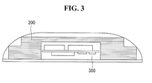
- FIG. 3 is a I-I' cross-sectional view of the mobile terminal of FIG. 1 according to one embodiment of the present invention.
- a battery pack 200 and PCB 300 are installed inside the housing of a mobile terminal 100 according to one embodiment of the present invention.
- a battery pack 200 surrounds the PCB 300 so that the heat generated from the PCB 300 can be prevented from being transferred directly to the surface of the mobile terminal.
- Part of the battery pack 200 can be disposed at least one surface of the PCB 300.
- part of the battery pack 200 can face directly at least one of an upper surface, a left-side surface, and a right-side surface.
- the battery pack 200 can include at least one heat conductive layer which radiates heat generated from the PCB 300.
- a heat conductive layer can include such materials as aluminum (Al) and copper (Cu). This implies that aluminum (Al) and copper
- (Cu) forming the battery pack 200 can play a role of a graphite sheet.
- Al and Cu have a high heat conductivity, heat generated from the PCB 300 can be radiated.
- the battery pack 200 plays a role of a radiation sheet. Due to this, an advantageous effect of reducing material costs can be achieved, tool.
- the overall thickness of the mobile terminal 100 can still be retained while capacity of the battery pack 200 can be increased.
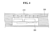
- FIG. 4 is a cross-sectional view of a mobile terminal to illustrate a radiation effect of a battery pack according to one embodiment of the present invention.
- part of the battery pack 200 plays a role of radiating heat generated from the PCB 300.
- the battery pack 200 can include a heat conductive layer with a high heat conductivity.
- a heat conductive layer can be formed from materials such as aluminum (Al) and copper (Cu).
- FIG. 5 is an enlarged cross-sectional view of an edge part of a battery pack according to one embodiment of the present invention.
- part of the battery pack 200 of a mobile terminal 100 can be formed in a shape to maximize an edge part of a housing.
- a housing can include an arch-shaped edge part 110 at least in one side thereof. Inside the arch-shaped edge part 110, layers forming the battery pack 200 are laminated such that at least one of thickness and volume of individual layers differs from each other. In other words, as one embodiment of the present invention, the edge part of the battery pack 200 can be formed in a stair shape.
- each layer included in the battery pack can have thickness different from each other.
- a first layer 201 can have a thickness of h1, a second layer 203 a thickness of h2, and a third layer 205 a thickness of h3.
- FIGs. 6 to 7 are enlarged cross-sectional views of an edge part of a battery pack according to one embodiment of the present invention.
- FIG. 6 illustrates a structure where PCB 300 and part of a battery pack 200 are disposed together in an edge part of a housing according to one embodiment of the present invention.
- the housing can include an arch-shaped edge part at least in one side thereof.
- Part of the battery pack 200 can be disposed on an upper surface of the PCB 300.
- Part of the battery pack 200 can be disposed in a gap formed between the PCB 300 and the edge part 100 of the housing.
- Part of the battery pack installed inside the arch-shaped edge part of the housing can consist of layers, each of which is different from the others in terms of at least one of thickness and volume.
- the battery pack 200 is first disposed inside the arch-shaped edge part 110, and structure of the battery pack 200 is formed to minimize unused space.
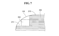
- FIG. 7 illustrates a structure where a component 350 included in the mobile terminal and part of the battery pack 200 are disposed in the edge part 110 of the housing according to one embodiment of the present invention.
- the battery pack can be installed in an elongated form to occupy the space assigned to at least one surface of at least one component included within the housing.
- the battery pack 200 can be installed therein. This implies that at least one of thickness and volume of the first layer 211 and the second layer 213, which are part of the battery pack, can be made to differ from each other.
- FIG. 8 illustrates the shape of a battery pack according to one embodiment of the present invention.
- FIG. 8(a) to 8(c) illustrate shapes of a battery pack according to various embodiments of the present invention.
- the edge part of the battery pack 200 can be formed in a stair shape.
- the battery pack can be formed in a ' ⁇ ' shape in order to secure space in which a component included in the mobile terminal 100 is disposed.
- part of the battery pack can be formed in a stair shape, and the other part can be formed in a ' ⁇ ' shape.
- the housing includes an arch-shaped edge part
- the inner space of the arch-shaped edge part can be fully utilized.
- the space excluding the area in which a component used by the mobile terminal, PCB, and the like are disposed can be fully utilized.
- the battery pack can comprise layers, each of which is different from the others in terms of at least one of thickness and volume.
- the battery pack can be formed to have a first cross-sectional shape differ from a second cross-sectional shape. This implies that shapes of cross-sections obtained by cutting the battery pack at arbitrary positions can differ from each other.
- capacity of the battery pack 200 can be increased. In other words, since the space remaining after disposing a component used by the mobile terminal 100, PCB, and others is fully utilized, capacity of the battery pack can be increased.
Landscapes
- Engineering & Computer Science (AREA)
- Theoretical Computer Science (AREA)
- Computer Hardware Design (AREA)
- General Engineering & Computer Science (AREA)
- Physics & Mathematics (AREA)
- Signal Processing (AREA)
- Human Computer Interaction (AREA)
- General Physics & Mathematics (AREA)
- Computer Networks & Wireless Communication (AREA)
- Microelectronics & Electronic Packaging (AREA)
- Thermal Sciences (AREA)
- Manufacturing & Machinery (AREA)
- Chemical & Material Sciences (AREA)
- Chemical Kinetics & Catalysis (AREA)
- Electrochemistry (AREA)
- General Chemical & Material Sciences (AREA)
- Battery Mounting, Suspending (AREA)
- Telephone Set Structure (AREA)
Abstract
Description
- This application claims the benefit of earlier filing date and right of priority to PCT Patent Application No.
PCT/KR2013/006350, filed on 16 July, 2013 - The present invention is related to a mobile terminal and more specifically, a mobile terminal capable of radiating heat generated from PCB by disposing part of a battery pack on one side of the PCB and capable of increasing capacity of the battery pack by utilizing a housing for the battery pack.
- As functions of terminals such as personal computers, laptop computers, cellular phones diversify, the terminals become multimedia players having multiple functions for capturing pictures or moving images, playing music, moving image files and games and receiving broadcasting programs.
- Terminals can be categorized as mobile terminals and stationary terminals. The mobile terminals can be further comprised of handheld terminals and vehicle mount terminals according to whether users can personally carry the terminals. Conventional terminals including mobile terminals provide an increasing number of complex and various functions.
- To support and enhance the increasing number of functions in a terminal, improving a structural part and/or a software part of the terminal would be desirable.
- In order to use a battery pack in a rectangular shape, modification of its shape and/or disposition may be needed.
- The present invention has been made in an effort to provide a mobile terminal capable of radiating heat generated from PCB by disposing part of a battery pack on one side of the PCB and capable of increasing capacity of the battery pack by utilizing a housing for the battery pack.
- To achieve the objective above, a mobile terminal according to one embodiment of the present invention comprises a housing; PCB installed inside the housing; and a battery pack disposed at least one side of the PCB and including at least one heat conductive layer radiating heat generated from the PCB.
- The battery pack can be disposed such that it directly faces at least one of an upper surface, a left-side surface, and a right-side surface of the PCB.
- The housing can include an arch-shaped edge on at least one side, and the battery pack can include the heat conductive layer on at least part of an inner area of the edge, where at least one of thickness and volume of the heat conductive layer is formed differently. The battery pack can be installed in an elongated form to occupy the space assigned to at least one surface of at least one component included within the housing.
- Also, to achieve the objective above, a mobile terminal according to one embodiment of the present invention comprises a housing; PCB installed inside the housing; and a battery pack including a layer where at least one of thickness and volume thereof is different, disposing at least part of the layer on an upper surface of the PCB, and having a first cross-sectional shape and a second cross-sectional shape being different from each other.
- A mobile terminal according to one embodiment radiates heat generated from PCB by disposing part of a battery pack on one surface of the PCB and increases capacity of the battery pack by utilizing a housing for the battery pack.
- The accompanying drawings, which are included to provide a further understanding of the invention and are incorporated in and constitute a part of this application, illustrate embodiment(s) of the invention and together with the description serve to explain the principle of the invention.
-
FIG. 1 is a front perspective view of a mobile terminal related to an embodiment; -
FIG. 2 is a rear perspective view of the mobile terminal; -
FIG. 3 is a I-I' cross-sectional view of the mobile terminal ofFIG. 1 according to one embodiment of the present invention; -
FIG. 4 is a cross-sectional view of a mobile terminal to illustrate a radiation effect of a battery pack according to one embodiment of the present invention; -
FIG. 5 is an enlarged cross-sectional view of an edge part of a battery pack according to one embodiment of the present invention; -
FIGs. 6 to 7 are enlarged cross-sectional views of an edge part of a battery pack according to one embodiment of the present invention; and -
FIG. 8 illustrates the shape of a battery pack according to one embodiment of the present invention. - Arrangements and embodiments may now be described more fully with reference to the accompanying drawings, in which exemplary embodiments may be shown. Embodiments may, however, be embodied in many different forms and should not be construed as being limited to embodiments set forth herein; rather, embodiments may be provided so that this disclosure will be thorough and complete, and will fully convey the concept to those skilled in the art.
- An electronic device may be described below with reference to the accompanying drawings. In the following description, suffixes "module" and "unit" may be given to components of the electronic device in consideration of only facilitation of description and do not have meanings or functions discriminated from each other.
- The electronic device may include a cellular phone, a smart phone, a laptop computer, a digital broadcasting terminal, personal digital assistants (PDA), a portable multimedia player (PMP), a navigation system and/or so on.
-
FIG. 1 is a front perspective view of a mobile terminal related to an embodiment, andFIG. 2 is a rear perspective view of the mobile terminal ofFIG. 2 . - As illustrated in
FIGS. 1 and2 , themobile terminal 100 according to an embodiment may have a bar-type body. The bar-type body may be formed by injection-molding a synthetic resin or may be formed of a metal, for example, stainless steel (STS), titanium, or the like. However, the present disclosure is not limited thereto and may be applicable to various structures such as a slide type, a folder type, a swing type, a swivel type, and the like, in which two or more bodies are combined to be relatively movable. - In an assembled state, a
front case 101 and abattery cover 102 may be exposed to the outside. - The
front case 101 may be a portion of a front side of themobile terminal 100. Adisplay 151, anaudio output unit 152, afront camera 121a, auser input unit 131, amicrophone 122, and the like, may be disposed in thefront case 101. - The
display 151 may be positioned in the front side of thefront case 101. Thedisplay 151 may display various types of information required for an operation of themobile terminal 100. Thedisplay 151 may display a 2D image and/or a 3D image. - The
audio output unit 152 may be a speaker outputting a reception sound, or the like. A plurality ofaudio output units 151 may be provided. For example, a plurality ofaudio output units 152 for outputting a reception sound or a bell sound may be provided. - The
front camera 121a may be positioned to capture a user. For example, the user may perform a video call with a different user based on his or her image captured through thefront camera 121a. - The
user input unit 131 may be manipulated to receive a command for controlling an operation of themobile terminal 100 and may include a plurality of manipulation units. Theuser input unit 131 may be sensed in a capacitive manner, and may generate light when a user input is applied thereto. - The
user input unit 131 may be generally referred to as a manipulating portion and any method may be employed if it is a tactile manner allowing the user to perform manipulation with a tactile feeling. For example, theuser input unit 131 may be a physical button. - The user input unit may be allocated a function having high frequency or a major function. For example, functions such as starting and terminating the
mobile terminal 100 and/or an application, volume adjustment, and the like, may be allocated to theuser input unit 131. - The
microphone 122 may be a device for obtaining a user voice, and the like. Themicrophone 122 may be positioned in a lower portion of themobile terminal 100. - As illustrated in
FIG. 2 , abattery cover 102 may be exposed to the rear side of themobile terminal 100 according to embodiment. Anearphone jack 171, anantenna 124, arear camera 121b, aside key button 170, and a second optical output unit 10b may be positioned in the rear side exposing thebattery camera 102. - The
earphone jack 171 may output a sound output from themobile terminal 100 through an earphone. Theearphone jack 171 may include a terminal for receiving a manipulation signal for controlling a function of the mobile terminal through a button provided in the earphone, as well as a terminal for transmitting an audio signal. - The
antenna 124 may be used to obtain a broadcast signal for viewing DMB, or the like. For example, in order to smoothly receive a broadcast signal, the user may draw theantenna 124 out of the terminal body to use it. - The
rear camera 121b may be positioned in the rear side of themobile terminal 100. Therear camera 121b may capture a stereoscopic image. For example, therear camera 121b may capture an image for a left eye and an image for a right eye. - A
camera flash 123 may be positioned to be adjacent to therear camera 121b. Thecamera flash 123 may operate when an image is captured. - The side
key button 170 may be positioned in the lateral side of themobile terminal 100. A sound volume of themobile terminal 100 may be adjusted through an operation of pushing an upper or lower side of thevolume adjustment switch 170. -
FIG. 3 is a I-I' cross-sectional view of the mobile terminal ofFIG. 1 according to one embodiment of the present invention. - As shown in the figure, a
battery pack 200 andPCB 300 are installed inside the housing of amobile terminal 100 according to one embodiment of the present invention. - A
battery pack 200 according to one embodiment of the present invention surrounds thePCB 300 so that the heat generated from thePCB 300 can be prevented from being transferred directly to the surface of the mobile terminal. - Part of the
battery pack 200 can be disposed at least one surface of thePCB 300. In other words, part of thebattery pack 200 can face directly at least one of an upper surface, a left-side surface, and a right-side surface. - The
battery pack 200 can include at least one heat conductive layer which radiates heat generated from thePCB 300. As one embodiment, a heat conductive layer can include such materials as aluminum (Al) and copper (Cu). This implies that aluminum (Al) and copper - (Cu) forming the
battery pack 200 can play a role of a graphite sheet. In other words, since Al and Cu have a high heat conductivity, heat generated from thePCB 300 can be radiated. - As a heat conductive layer made from materials with a high heat conductivity included in the
battery pack 200 is installed such that the heat conductive layer surrounds thePCB 300, thebattery pack 200 plays a role of a radiation sheet. Due to this, an advantageous effect of reducing material costs can be achieved, tool. - Also, by installing part of the
battery pack 200 in a gap formed between thePCB 300 and the housing, the overall thickness of themobile terminal 100 can still be retained while capacity of thebattery pack 200 can be increased. -
FIG. 4 is a cross-sectional view of a mobile terminal to illustrate a radiation effect of a battery pack according to one embodiment of the present invention. - As shown in the figure, part of the
battery pack 200 according to one embodiment of the present invention plays a role of radiating heat generated from thePCB 300. - On an upper surface of the
PCB 300, part of thebattery pack 200 can be disposed. Thebattery pack 200 can include a heat conductive layer with a high heat conductivity. As one embodiment, a heat conductive layer can be formed from materials such as aluminum (Al) and copper (Cu). - In case the PCB is exposed to the surface of the mobile terminal, heat generated from the PCB can be transferred to the terminal directly. Since part of the
battery pack 200 is installed on an upper surface of the PCB, it can play a role of a graphite sheet for heat radiation. Due to this structure, an additional effect of reducing material costs can be obtained. -
FIG. 5 is an enlarged cross-sectional view of an edge part of a battery pack according to one embodiment of the present invention. - As shown in the figure, part of the
battery pack 200 of amobile terminal 100 according to one embodiment of the present invention can be formed in a shape to maximize an edge part of a housing. - A housing can include an arch-shaped
edge part 110 at least in one side thereof. Inside the arch-shapededge part 110, layers forming thebattery pack 200 are laminated such that at least one of thickness and volume of individual layers differs from each other. In other words, as one embodiment of the present invention, the edge part of thebattery pack 200 can be formed in a stair shape. - Based on the arch-shaped
edge part 110, each layer included in the battery pack can have thickness different from each other. For example, afirst layer 201 can have a thickness of h1, a second layer 203 a thickness of h2, and a third layer 205 a thickness of h3. - Since part of the
battery pack 200 disposed in the arch-shapededge part 110 are installed in a stair shape, unused space after installation of thebattery pack 200 can be minimized. Accordingly, while a housing is utilized, capacity of thebattery pack 200 can be increased to the maximum. -
FIGs. 6 to 7 are enlarged cross-sectional views of an edge part of a battery pack according to one embodiment of the present invention. -
FIG. 6 illustrates a structure wherePCB 300 and part of abattery pack 200 are disposed together in an edge part of a housing according to one embodiment of the present invention. - The housing can include an arch-shaped edge part at least in one side thereof. Part of the
battery pack 200 can be disposed on an upper surface of thePCB 300. - Part of the
battery pack 200 can be disposed in a gap formed between thePCB 300 and theedge part 100 of the housing. Part of the battery pack installed inside the arch-shaped edge part of the housing can consist of layers, each of which is different from the others in terms of at least one of thickness and volume. - In other words, the
battery pack 200 is first disposed inside the arch-shapededge part 110, and structure of thebattery pack 200 is formed to minimize unused space. This implies that the inner space of the arch-shapededge part 110 of the housing can be fully utilized by forming thickness or volume of thefirst layer 207 and thesecond layer 209, which are part of the battery pack, to differ from each other. - By utilizing the inner space of the housing, capacity of the
battery pack 200 can be increased. Also, since the heat conductive layer included in thebattery pack 200 disposed on an upper surface of the PCB plays a role of graphite sheet, an advantageous effect of radiating heat generated from the PCB can be achieved. -
FIG. 7 illustrates a structure where acomponent 350 included in the mobile terminal and part of thebattery pack 200 are disposed in theedge part 110 of the housing according to one embodiment of the present invention. - The battery pack can be installed in an elongated form to occupy the space assigned to at least one surface of at least one component included within the housing.
- In other words, if there is space available in a lower surface of at least one
component 350, thebattery pack 200 can be installed therein. This implies that at least one of thickness and volume of thefirst layer 211 and thesecond layer 213, which are part of the battery pack, can be made to differ from each other. - Since the remaining space formed after disposition of a
component 350 included in themobile terminal 100 is fully utilized, an advantageous effect of increasing capacity of a battery pack can be obtained. -
FIG. 8 illustrates the shape of a battery pack according to one embodiment of the present invention. -
FIG. 8(a) to 8(c) illustrate shapes of a battery pack according to various embodiments of the present invention. - As shown in
FIG. 8(a) , as one embodiment of the present invention, in case the housing includes an arch-shaped edge part, the edge part of thebattery pack 200 can be formed in a stair shape. - As shown in
FIG. 8(b) , as one embodiment of the present invention, the battery pack can be formed in a '¬' shape in order to secure space in which a component included in themobile terminal 100 is disposed. - As shown in
FIG. 8(c) , as one embodiment of the present invention, part of the battery pack can be formed in a stair shape, and the other part can be formed in a '¬' shape. In other words, in case the housing includes an arch-shaped edge part, the inner space of the arch-shaped edge part can be fully utilized. Also the space excluding the area in which a component used by the mobile terminal, PCB, and the like are disposed can be fully utilized. - As shown in
FIG. 8 , the battery pack can comprise layers, each of which is different from the others in terms of at least one of thickness and volume. In other words, the battery pack can be formed to have a first cross-sectional shape differ from a second cross-sectional shape. This implies that shapes of cross-sections obtained by cutting the battery pack at arbitrary positions can differ from each other. - As the inner space of the housing of the
mobile terminal 100 is fully utilized, capacity of thebattery pack 200 can be increased. In other words, since the space remaining after disposing a component used by themobile terminal 100, PCB, and others is fully utilized, capacity of the battery pack can be increased. - Although embodiments have been described with reference to a number of illustrative embodiments thereof, it should be understood that numerous other modifications and embodiments can be devised by those skilled in the art that will fall within the spirit and scope of the principles of this disclosure. More particularly, various variations and modifications are possible in the component parts and/or arrangements of the subject combination arrangement within the scope of the disclosure, the drawings and the appended claims. In addition to variations and modifications in the component parts and/or arrangements, alternative uses will also be apparent to those skilled in the art.
Claims (5)
- A mobile terminal, comprising:a housing;PCB installed inside the housing; anda battery pack disposed at least one side of the PCB and including at least one heat conductive layer radiating heat generated from the PCB.
- The mobile terminal of claim 1, wherein the battery pack is disposed such that it directly faces at least one of an upper surface, a left-side surface, and a right-side surface of the PCB.
- The mobile terminal of claim 1, wherein the housing includes an arch-shaped edge on at least one side; the battery pack includes the heat conductive layer on at least part of an inner area of the edge; and at least one of thickness and volume of the heat conductive layer is formed differently.
- The mobile terminal of claim 1, wherein the battery pack is installed in an elongated form to occupy space assigned to at least one surface of at least one component included within the housing.
- A mobile terminal, comprising:a housing;PCB installed inside the housing; anda battery pack including a layer wherein at least one of thickness and volume thereof is different, disposing at least part of the layer on an upper surface of the PCB, and having a first cross-sectional shape and a second cross-sectional shape being different from each other.
Applications Claiming Priority (2)
| Application Number | Priority Date | Filing Date | Title |
|---|---|---|---|
| KR1020120088164A KR101976180B1 (en) | 2012-08-13 | 2012-08-13 | Mobile terminal |
| PCT/KR2013/006350 WO2014027760A1 (en) | 2012-08-13 | 2013-07-16 | Mobile terminal |
Publications (3)
| Publication Number | Publication Date |
|---|---|
| EP2884671A1 true EP2884671A1 (en) | 2015-06-17 |
| EP2884671A4 EP2884671A4 (en) | 2016-03-30 |
| EP2884671B1 EP2884671B1 (en) | 2019-04-17 |
Family
ID=50101314
Family Applications (1)
| Application Number | Title | Priority Date | Filing Date |
|---|---|---|---|
| EP13829514.2A Not-in-force EP2884671B1 (en) | 2012-08-13 | 2013-07-16 | Mobile terminal |
Country Status (5)
| Country | Link |
|---|---|
| US (1) | US9693444B2 (en) |
| EP (1) | EP2884671B1 (en) |
| KR (1) | KR101976180B1 (en) |
| CN (1) | CN104584444B (en) |
| WO (1) | WO2014027760A1 (en) |
Cited By (2)
| Publication number | Priority date | Publication date | Assignee | Title |
|---|---|---|---|---|
| JP2024120823A (en) * | 2023-02-24 | 2024-09-05 | 北京小米移動軟件有限公司 | Electronics |
| JP2024120822A (en) * | 2023-02-24 | 2024-09-05 | 北京小米移動軟件有限公司 | Electronics |
Families Citing this family (3)
| Publication number | Priority date | Publication date | Assignee | Title |
|---|---|---|---|---|
| US20140321033A1 (en) * | 2013-04-26 | 2014-10-30 | Motorola Mobility Llc | Enhanced mobile electronic device and battery pack |
| CN109525004A (en) * | 2017-09-19 | 2019-03-26 | 北京小米移动软件有限公司 | Electronic equipment, charging method and device, method of supplying power to and device |
| CN110086912A (en) * | 2019-04-29 | 2019-08-02 | 南昌黑鲨科技有限公司 | A kind of terminal |
Family Cites Families (22)
| Publication number | Priority date | Publication date | Assignee | Title |
|---|---|---|---|---|
| JP3727840B2 (en) * | 2000-09-29 | 2005-12-21 | 株式会社東芝 | Battery pack and portable electronic device |
| KR100440934B1 (en) | 2002-02-06 | 2004-07-21 | 삼성에스디아이 주식회사 | Secondary battery |
| KR100490903B1 (en) * | 2002-12-28 | 2005-05-24 | 주식회사 팬택앤큐리텔 | Cellular Phone With Battery Having Function Of Heat Dissipation |
| US20040132503A1 (en) | 2003-01-03 | 2004-07-08 | Chia-Pin Chiu | Thermal management for telecommunication devices |
| KR100585754B1 (en) | 2003-12-18 | 2006-06-07 | 엘지전자 주식회사 | Keypad heat sink of portable terminal |
| KR100629517B1 (en) * | 2005-03-07 | 2006-09-28 | 삼성전자주식회사 | Handheld devices |
| KR100677620B1 (en) * | 2005-11-22 | 2007-02-02 | 삼성전자주식회사 | Electronic device cooling method and improved cooling efficiency |
| KR100852589B1 (en) * | 2006-07-21 | 2008-08-14 | (주)케이티에프테크놀로지스 | Portable terminal with heat dissipation structure |
| US20100136405A1 (en) * | 2008-04-02 | 2010-06-03 | Karl Johnson | Battery pack with optimized mechanical, electrical, and thermal management |
| JP2010073606A (en) * | 2008-09-22 | 2010-04-02 | Panasonic Corp | Portable electronic equipment |
| KR101179364B1 (en) * | 2008-09-22 | 2012-09-03 | 파나소닉 주식회사 | Portable Electronic Device |
| US20110183183A1 (en) * | 2010-01-26 | 2011-07-28 | Grady Steven C | Battery arrays, constructions and method |
| US9040187B2 (en) * | 2010-07-13 | 2015-05-26 | Apple, Inc. | Battery pack with cells of different capacities electrically coupled in parallel |
| US8940429B2 (en) * | 2010-07-16 | 2015-01-27 | Apple Inc. | Construction of non-rectangular batteries |
| US8477492B2 (en) * | 2010-08-19 | 2013-07-02 | Apple Inc. | Formed PCB |
| US8391010B2 (en) * | 2010-08-19 | 2013-03-05 | Apple Inc. | Internal frame optimized for stiffness and heat transfer |
| US8432696B2 (en) * | 2010-12-01 | 2013-04-30 | Apple Inc. | Using a battery pack to facilitate thermal transfer in a portable electronic device |
| US8989821B2 (en) * | 2011-08-31 | 2015-03-24 | Apple Inc. | Battery configurations for electronic devices |
| US9103021B2 (en) * | 2011-11-17 | 2015-08-11 | Apple Inc. | Amorphous diamond-like carbon coatings for increasing the thermal conductivity of structural frames in portable electronic devices |
| US9095077B2 (en) * | 2011-11-30 | 2015-07-28 | Apple Inc. | Graphene heat dissipators in portable electronic devices |
| KR20130062197A (en) * | 2011-12-02 | 2013-06-12 | 삼성에스디아이 주식회사 | Battery pack and method of manufacturing thereof |
| US9177503B2 (en) * | 2012-05-31 | 2015-11-03 | Apple Inc. | Display having integrated thermal sensors |
-
2012
- 2012-08-13 KR KR1020120088164A patent/KR101976180B1/en not_active Expired - Fee Related
-
2013
- 2013-07-16 US US14/421,259 patent/US9693444B2/en not_active Expired - Fee Related
- 2013-07-16 WO PCT/KR2013/006350 patent/WO2014027760A1/en not_active Ceased
- 2013-07-16 EP EP13829514.2A patent/EP2884671B1/en not_active Not-in-force
- 2013-07-16 CN CN201380043128.XA patent/CN104584444B/en not_active Expired - Fee Related
Cited By (2)
| Publication number | Priority date | Publication date | Assignee | Title |
|---|---|---|---|---|
| JP2024120823A (en) * | 2023-02-24 | 2024-09-05 | 北京小米移動軟件有限公司 | Electronics |
| JP2024120822A (en) * | 2023-02-24 | 2024-09-05 | 北京小米移動軟件有限公司 | Electronics |
Also Published As
| Publication number | Publication date |
|---|---|
| EP2884671A4 (en) | 2016-03-30 |
| KR101976180B1 (en) | 2019-05-08 |
| US20150342024A1 (en) | 2015-11-26 |
| EP2884671B1 (en) | 2019-04-17 |
| CN104584444B (en) | 2017-03-08 |
| CN104584444A (en) | 2015-04-29 |
| WO2014027760A1 (en) | 2014-02-20 |
| KR20140022130A (en) | 2014-02-24 |
| US9693444B2 (en) | 2017-06-27 |
Similar Documents
| Publication | Publication Date | Title |
|---|---|---|
| US9608314B1 (en) | Mobile terminal | |
| JP6972206B2 (en) | Mobile terminal | |
| CN103199882B (en) | Mobile terminal | |
| CN111183626B (en) | Mobile terminal | |
| KR101240273B1 (en) | Mobile terminal | |
| CN105052042B (en) | Mobile terminal | |
| EP3393108B1 (en) | Mobile terminal having case, method for manufacturing same | |
| KR102042264B1 (en) | Mobile terminal | |
| EP2884671A1 (en) | Mobile terminal | |
| KR101969801B1 (en) | Mobile terminal | |
| CN103581375A (en) | Mobile terminal | |
| KR101632408B1 (en) | Watch type mobile terminal | |
| CN102572028A (en) | Cover for a mobile terminal | |
| US10582104B2 (en) | Electronic device having camera device and method for fabricating camera device | |
| EP2610961A2 (en) | Antenna assembly, method of manufacturing antenna assembly and mobile terminal having antenna assembly | |
| KR20150027593A (en) | Mobile terminal | |
| KR101976182B1 (en) | Fpcb assembly and mobile terminal having it | |
| KR20130092739A (en) | Heat spreading sheet and mobile terminal having it | |
| KR20130055310A (en) | Terminal assemble and mobile terminal comprising it | |
| KR20130054552A (en) | Vibration motor assembly and mobile terminal comprising it | |
| KR101727511B1 (en) | Portable terminal | |
| KR20130050573A (en) | Pcb assembly and mobile termial comprising it | |
| KR20130064353A (en) | Pcb assembly and mobile termnial having it | |
| KR20140016472A (en) | Insert pin assembly and mobile terminal having it |
Legal Events
| Date | Code | Title | Description |
|---|---|---|---|
| PUAI | Public reference made under article 153(3) epc to a published international application that has entered the european phase |
Free format text: ORIGINAL CODE: 0009012 |
|
| 17P | Request for examination filed |
Effective date: 20150206 |
|
| AK | Designated contracting states |
Kind code of ref document: A1 Designated state(s): AL AT BE BG CH CY CZ DE DK EE ES FI FR GB GR HR HU IE IS IT LI LT LU LV MC MK MT NL NO PL PT RO RS SE SI SK SM TR |
|
| AX | Request for extension of the european patent |
Extension state: BA ME |
|
| DAX | Request for extension of the european patent (deleted) | ||
| RA4 | Supplementary search report drawn up and despatched (corrected) |
Effective date: 20160229 |
|
| RIC1 | Information provided on ipc code assigned before grant |
Ipc: G06F 1/20 20060101ALI20160223BHEP Ipc: H04B 1/38 20060101AFI20160223BHEP Ipc: H04B 1/036 20060101ALI20160223BHEP Ipc: H04M 1/02 20060101ALI20160223BHEP |
|
| STAA | Information on the status of an ep patent application or granted ep patent |
Free format text: STATUS: EXAMINATION IS IN PROGRESS |
|
| 17Q | First examination report despatched |
Effective date: 20180306 |
|
| GRAP | Despatch of communication of intention to grant a patent |
Free format text: ORIGINAL CODE: EPIDOSNIGR1 |
|
| STAA | Information on the status of an ep patent application or granted ep patent |
Free format text: STATUS: GRANT OF PATENT IS INTENDED |
|
| INTG | Intention to grant announced |
Effective date: 20181113 |
|
| GRAS | Grant fee paid |
Free format text: ORIGINAL CODE: EPIDOSNIGR3 |
|
| GRAA | (expected) grant |
Free format text: ORIGINAL CODE: 0009210 |
|
| STAA | Information on the status of an ep patent application or granted ep patent |
Free format text: STATUS: THE PATENT HAS BEEN GRANTED |
|
| AK | Designated contracting states |
Kind code of ref document: B1 Designated state(s): AL AT BE BG CH CY CZ DE DK EE ES FI FR GB GR HR HU IE IS IT LI LT LU LV MC MK MT NL NO PL PT RO RS SE SI SK SM TR |
|
| REG | Reference to a national code |
Ref country code: GB Ref legal event code: FG4D |
|
| REG | Reference to a national code |
Ref country code: CH Ref legal event code: EP |
|
| REG | Reference to a national code |
Ref country code: DE Ref legal event code: R096 Ref document number: 602013054102 Country of ref document: DE |
|
| REG | Reference to a national code |
Ref country code: AT Ref legal event code: REF Ref document number: 1122675 Country of ref document: AT Kind code of ref document: T Effective date: 20190515 Ref country code: IE Ref legal event code: FG4D |
|
| REG | Reference to a national code |
Ref country code: NL Ref legal event code: MP Effective date: 20190417 |
|
| REG | Reference to a national code |
Ref country code: LT Ref legal event code: MG4D |
|
| PG25 | Lapsed in a contracting state [announced via postgrant information from national office to epo] |
Ref country code: NL Free format text: LAPSE BECAUSE OF FAILURE TO SUBMIT A TRANSLATION OF THE DESCRIPTION OR TO PAY THE FEE WITHIN THE PRESCRIBED TIME-LIMIT Effective date: 20190417 |
|
| PG25 | Lapsed in a contracting state [announced via postgrant information from national office to epo] |
Ref country code: AL Free format text: LAPSE BECAUSE OF FAILURE TO SUBMIT A TRANSLATION OF THE DESCRIPTION OR TO PAY THE FEE WITHIN THE PRESCRIBED TIME-LIMIT Effective date: 20190417 Ref country code: PT Free format text: LAPSE BECAUSE OF FAILURE TO SUBMIT A TRANSLATION OF THE DESCRIPTION OR TO PAY THE FEE WITHIN THE PRESCRIBED TIME-LIMIT Effective date: 20190817 Ref country code: FI Free format text: LAPSE BECAUSE OF FAILURE TO SUBMIT A TRANSLATION OF THE DESCRIPTION OR TO PAY THE FEE WITHIN THE PRESCRIBED TIME-LIMIT Effective date: 20190417 Ref country code: HR Free format text: LAPSE BECAUSE OF FAILURE TO SUBMIT A TRANSLATION OF THE DESCRIPTION OR TO PAY THE FEE WITHIN THE PRESCRIBED TIME-LIMIT Effective date: 20190417 Ref country code: LT Free format text: LAPSE BECAUSE OF FAILURE TO SUBMIT A TRANSLATION OF THE DESCRIPTION OR TO PAY THE FEE WITHIN THE PRESCRIBED TIME-LIMIT Effective date: 20190417 Ref country code: SE Free format text: LAPSE BECAUSE OF FAILURE TO SUBMIT A TRANSLATION OF THE DESCRIPTION OR TO PAY THE FEE WITHIN THE PRESCRIBED TIME-LIMIT Effective date: 20190417 Ref country code: NO Free format text: LAPSE BECAUSE OF FAILURE TO SUBMIT A TRANSLATION OF THE DESCRIPTION OR TO PAY THE FEE WITHIN THE PRESCRIBED TIME-LIMIT Effective date: 20190717 Ref country code: ES Free format text: LAPSE BECAUSE OF FAILURE TO SUBMIT A TRANSLATION OF THE DESCRIPTION OR TO PAY THE FEE WITHIN THE PRESCRIBED TIME-LIMIT Effective date: 20190417 |
|
| PG25 | Lapsed in a contracting state [announced via postgrant information from national office to epo] |
Ref country code: BG Free format text: LAPSE BECAUSE OF FAILURE TO SUBMIT A TRANSLATION OF THE DESCRIPTION OR TO PAY THE FEE WITHIN THE PRESCRIBED TIME-LIMIT Effective date: 20190717 Ref country code: GR Free format text: LAPSE BECAUSE OF FAILURE TO SUBMIT A TRANSLATION OF THE DESCRIPTION OR TO PAY THE FEE WITHIN THE PRESCRIBED TIME-LIMIT Effective date: 20190718 Ref country code: PL Free format text: LAPSE BECAUSE OF FAILURE TO SUBMIT A TRANSLATION OF THE DESCRIPTION OR TO PAY THE FEE WITHIN THE PRESCRIBED TIME-LIMIT Effective date: 20190417 Ref country code: RS Free format text: LAPSE BECAUSE OF FAILURE TO SUBMIT A TRANSLATION OF THE DESCRIPTION OR TO PAY THE FEE WITHIN THE PRESCRIBED TIME-LIMIT Effective date: 20190417 Ref country code: LV Free format text: LAPSE BECAUSE OF FAILURE TO SUBMIT A TRANSLATION OF THE DESCRIPTION OR TO PAY THE FEE WITHIN THE PRESCRIBED TIME-LIMIT Effective date: 20190417 |
|
| REG | Reference to a national code |
Ref country code: AT Ref legal event code: MK05 Ref document number: 1122675 Country of ref document: AT Kind code of ref document: T Effective date: 20190417 |
|
| PG25 | Lapsed in a contracting state [announced via postgrant information from national office to epo] |
Ref country code: IS Free format text: LAPSE BECAUSE OF FAILURE TO SUBMIT A TRANSLATION OF THE DESCRIPTION OR TO PAY THE FEE WITHIN THE PRESCRIBED TIME-LIMIT Effective date: 20190817 |
|
| REG | Reference to a national code |
Ref country code: DE Ref legal event code: R097 Ref document number: 602013054102 Country of ref document: DE |
|
| PG25 | Lapsed in a contracting state [announced via postgrant information from national office to epo] |
Ref country code: CZ Free format text: LAPSE BECAUSE OF FAILURE TO SUBMIT A TRANSLATION OF THE DESCRIPTION OR TO PAY THE FEE WITHIN THE PRESCRIBED TIME-LIMIT Effective date: 20190417 Ref country code: RO Free format text: LAPSE BECAUSE OF FAILURE TO SUBMIT A TRANSLATION OF THE DESCRIPTION OR TO PAY THE FEE WITHIN THE PRESCRIBED TIME-LIMIT Effective date: 20190417 Ref country code: AT Free format text: LAPSE BECAUSE OF FAILURE TO SUBMIT A TRANSLATION OF THE DESCRIPTION OR TO PAY THE FEE WITHIN THE PRESCRIBED TIME-LIMIT Effective date: 20190417 Ref country code: EE Free format text: LAPSE BECAUSE OF FAILURE TO SUBMIT A TRANSLATION OF THE DESCRIPTION OR TO PAY THE FEE WITHIN THE PRESCRIBED TIME-LIMIT Effective date: 20190417 Ref country code: DK Free format text: LAPSE BECAUSE OF FAILURE TO SUBMIT A TRANSLATION OF THE DESCRIPTION OR TO PAY THE FEE WITHIN THE PRESCRIBED TIME-LIMIT Effective date: 20190417 Ref country code: SK Free format text: LAPSE BECAUSE OF FAILURE TO SUBMIT A TRANSLATION OF THE DESCRIPTION OR TO PAY THE FEE WITHIN THE PRESCRIBED TIME-LIMIT Effective date: 20190417 |
|
| PLBE | No opposition filed within time limit |
Free format text: ORIGINAL CODE: 0009261 |
|
| STAA | Information on the status of an ep patent application or granted ep patent |
Free format text: STATUS: NO OPPOSITION FILED WITHIN TIME LIMIT |
|
| PG25 | Lapsed in a contracting state [announced via postgrant information from national office to epo] |
Ref country code: MC Free format text: LAPSE BECAUSE OF FAILURE TO SUBMIT A TRANSLATION OF THE DESCRIPTION OR TO PAY THE FEE WITHIN THE PRESCRIBED TIME-LIMIT Effective date: 20190417 Ref country code: IT Free format text: LAPSE BECAUSE OF FAILURE TO SUBMIT A TRANSLATION OF THE DESCRIPTION OR TO PAY THE FEE WITHIN THE PRESCRIBED TIME-LIMIT Effective date: 20190417 Ref country code: SM Free format text: LAPSE BECAUSE OF FAILURE TO SUBMIT A TRANSLATION OF THE DESCRIPTION OR TO PAY THE FEE WITHIN THE PRESCRIBED TIME-LIMIT Effective date: 20190417 |
|
| REG | Reference to a national code |
Ref country code: CH Ref legal event code: PL |
|
| 26N | No opposition filed |
Effective date: 20200120 |
|
| PG25 | Lapsed in a contracting state [announced via postgrant information from national office to epo] |
Ref country code: TR Free format text: LAPSE BECAUSE OF FAILURE TO SUBMIT A TRANSLATION OF THE DESCRIPTION OR TO PAY THE FEE WITHIN THE PRESCRIBED TIME-LIMIT Effective date: 20190417 |
|
| REG | Reference to a national code |
Ref country code: BE Ref legal event code: MM Effective date: 20190731 |
|
| PG25 | Lapsed in a contracting state [announced via postgrant information from national office to epo] |
Ref country code: LU Free format text: LAPSE BECAUSE OF NON-PAYMENT OF DUE FEES Effective date: 20190716 Ref country code: BE Free format text: LAPSE BECAUSE OF NON-PAYMENT OF DUE FEES Effective date: 20190731 Ref country code: SI Free format text: LAPSE BECAUSE OF FAILURE TO SUBMIT A TRANSLATION OF THE DESCRIPTION OR TO PAY THE FEE WITHIN THE PRESCRIBED TIME-LIMIT Effective date: 20190417 Ref country code: CH Free format text: LAPSE BECAUSE OF NON-PAYMENT OF DUE FEES Effective date: 20190731 Ref country code: LI Free format text: LAPSE BECAUSE OF NON-PAYMENT OF DUE FEES Effective date: 20190731 |
|
| PG25 | Lapsed in a contracting state [announced via postgrant information from national office to epo] |
Ref country code: IE Free format text: LAPSE BECAUSE OF NON-PAYMENT OF DUE FEES Effective date: 20190716 |
|
| PGFP | Annual fee paid to national office [announced via postgrant information from national office to epo] |
Ref country code: FR Payment date: 20200609 Year of fee payment: 8 |
|
| PGFP | Annual fee paid to national office [announced via postgrant information from national office to epo] |
Ref country code: GB Payment date: 20200608 Year of fee payment: 8 |
|
| PGFP | Annual fee paid to national office [announced via postgrant information from national office to epo] |
Ref country code: DE Payment date: 20200605 Year of fee payment: 8 |
|
| PG25 | Lapsed in a contracting state [announced via postgrant information from national office to epo] |
Ref country code: CY Free format text: LAPSE BECAUSE OF FAILURE TO SUBMIT A TRANSLATION OF THE DESCRIPTION OR TO PAY THE FEE WITHIN THE PRESCRIBED TIME-LIMIT Effective date: 20190417 |
|
| PG25 | Lapsed in a contracting state [announced via postgrant information from national office to epo] |
Ref country code: MT Free format text: LAPSE BECAUSE OF FAILURE TO SUBMIT A TRANSLATION OF THE DESCRIPTION OR TO PAY THE FEE WITHIN THE PRESCRIBED TIME-LIMIT Effective date: 20190417 Ref country code: HU Free format text: LAPSE BECAUSE OF FAILURE TO SUBMIT A TRANSLATION OF THE DESCRIPTION OR TO PAY THE FEE WITHIN THE PRESCRIBED TIME-LIMIT; INVALID AB INITIO Effective date: 20130716 |
|
| REG | Reference to a national code |
Ref country code: DE Ref legal event code: R119 Ref document number: 602013054102 Country of ref document: DE |
|
| GBPC | Gb: european patent ceased through non-payment of renewal fee |
Effective date: 20210716 |
|
| PG25 | Lapsed in a contracting state [announced via postgrant information from national office to epo] |
Ref country code: GB Free format text: LAPSE BECAUSE OF NON-PAYMENT OF DUE FEES Effective date: 20210716 Ref country code: DE Free format text: LAPSE BECAUSE OF NON-PAYMENT OF DUE FEES Effective date: 20220201 |
|
| PG25 | Lapsed in a contracting state [announced via postgrant information from national office to epo] |
Ref country code: FR Free format text: LAPSE BECAUSE OF NON-PAYMENT OF DUE FEES Effective date: 20210731 |
|
| PG25 | Lapsed in a contracting state [announced via postgrant information from national office to epo] |
Ref country code: MK Free format text: LAPSE BECAUSE OF FAILURE TO SUBMIT A TRANSLATION OF THE DESCRIPTION OR TO PAY THE FEE WITHIN THE PRESCRIBED TIME-LIMIT Effective date: 20190417 |