EP2884622A1 - Non-contact power supply device and non-contact power supply method - Google Patents
Non-contact power supply device and non-contact power supply method Download PDFInfo
- Publication number
- EP2884622A1 EP2884622A1 EP14275240.1A EP14275240A EP2884622A1 EP 2884622 A1 EP2884622 A1 EP 2884622A1 EP 14275240 A EP14275240 A EP 14275240A EP 2884622 A1 EP2884622 A1 EP 2884622A1
- Authority
- EP
- European Patent Office
- Prior art keywords
- power supply
- supply device
- power
- beacon
- receiving device
- Prior art date
- Legal status (The legal status is an assumption and is not a legal conclusion. Google has not performed a legal analysis and makes no representation as to the accuracy of the status listed.)
- Withdrawn
Links
- 238000000034 method Methods 0.000 title abstract description 6
- 230000005540 biological transmission Effects 0.000 claims description 13
- 238000001514 detection method Methods 0.000 claims 1
- 238000010586 diagram Methods 0.000 description 12
- 230000008878 coupling Effects 0.000 description 7
- 238000010168 coupling process Methods 0.000 description 7
- 238000005859 coupling reaction Methods 0.000 description 7
- 230000008054 signal transmission Effects 0.000 description 3
- 230000008901 benefit Effects 0.000 description 2
- 230000000694 effects Effects 0.000 description 2
- 230000003068 static effect Effects 0.000 description 2
- 239000004020 conductor Substances 0.000 description 1
- 230000009351 contact transmission Effects 0.000 description 1
- 230000006698 induction Effects 0.000 description 1
- 238000012986 modification Methods 0.000 description 1
- 230000004048 modification Effects 0.000 description 1
Images


Classifications
-
- H02J5/005—
-
- H—ELECTRICITY
- H02—GENERATION; CONVERSION OR DISTRIBUTION OF ELECTRIC POWER
- H02J—CIRCUIT ARRANGEMENTS OR SYSTEMS FOR SUPPLYING OR DISTRIBUTING ELECTRIC POWER; SYSTEMS FOR STORING ELECTRIC ENERGY
- H02J50/00—Circuit arrangements or systems for wireless supply or distribution of electric power
- H02J50/80—Circuit arrangements or systems for wireless supply or distribution of electric power involving the exchange of data, concerning supply or distribution of electric power, between transmitting devices and receiving devices
-
- H—ELECTRICITY
- H02—GENERATION; CONVERSION OR DISTRIBUTION OF ELECTRIC POWER
- H02J—CIRCUIT ARRANGEMENTS OR SYSTEMS FOR SUPPLYING OR DISTRIBUTING ELECTRIC POWER; SYSTEMS FOR STORING ELECTRIC ENERGY
- H02J50/00—Circuit arrangements or systems for wireless supply or distribution of electric power
- H02J50/10—Circuit arrangements or systems for wireless supply or distribution of electric power using inductive coupling
- H02J50/12—Circuit arrangements or systems for wireless supply or distribution of electric power using inductive coupling of the resonant type
-
- H—ELECTRICITY
- H02—GENERATION; CONVERSION OR DISTRIBUTION OF ELECTRIC POWER
- H02J—CIRCUIT ARRANGEMENTS OR SYSTEMS FOR SUPPLYING OR DISTRIBUTING ELECTRIC POWER; SYSTEMS FOR STORING ELECTRIC ENERGY
- H02J50/00—Circuit arrangements or systems for wireless supply or distribution of electric power
- H02J50/90—Circuit arrangements or systems for wireless supply or distribution of electric power involving detection or optimisation of position, e.g. alignment
-
- H—ELECTRICITY
- H02—GENERATION; CONVERSION OR DISTRIBUTION OF ELECTRIC POWER
- H02J—CIRCUIT ARRANGEMENTS OR SYSTEMS FOR SUPPLYING OR DISTRIBUTING ELECTRIC POWER; SYSTEMS FOR STORING ELECTRIC ENERGY
- H02J7/00—Circuit arrangements for charging or depolarising batteries or for supplying loads from batteries
- H02J7/00032—Circuit arrangements for charging or depolarising batteries or for supplying loads from batteries characterised by data exchange
- H02J7/00034—Charger exchanging data with an electronic device, i.e. telephone, whose internal battery is under charge
-
- H04B5/79—
-
- H—ELECTRICITY
- H02—GENERATION; CONVERSION OR DISTRIBUTION OF ELECTRIC POWER
- H02J—CIRCUIT ARRANGEMENTS OR SYSTEMS FOR SUPPLYING OR DISTRIBUTING ELECTRIC POWER; SYSTEMS FOR STORING ELECTRIC ENERGY
- H02J9/00—Circuit arrangements for emergency or stand-by power supply, e.g. for emergency lighting
- H02J9/005—Circuit arrangements for emergency or stand-by power supply, e.g. for emergency lighting using a power saving mode
Definitions
- the present disclosure relates to a non-contact power supply device and a non-contact power supply method in which power is transmitted in a contactless manner.
- a power supply device for transferring power from an external power source to the electronic device is required.
- a wired power supply device directly connected to an electronic device via a connector, or the like, to supply power to a battery included in the electronic device, is currently in widespread use.
- power may be supplied to the battery provided in the electronic device in a contactless manner through a magnetic induction effect or a magnetic resonance effect.
- a non-contact power supply device may transmit a short beacon to determine whether or not a power receiving device which receives power in a contactless manner is in proximity to a charging surface of the power supply device.
- the non-contact power supply device may not properly recognize the power receiving device in the vicinity thereof, due to reliance on a coupling coefficient between a coil of the charging surface of the non-contact power supply device and a coil of the power receiving device.
- the non-contact power supply device may transmit a relatively long beacon to wake-up a communications circuit of the power receiving device so as to perform a normal charging operation. In such a case, the communications circuit of the power receiving device may not be woken-up, due to problems with the coupling coefficient between the coil of the charging surface and the coil of the power receiving device.
- Patent Document 1 Korean Patent Laid-Open Publication No. 10-2011-0009227
- An aspect of the present disclosure may provide a non-contact power supply device and a non-contact power supply method in which signal levels of a short beacon or a long beacon are varied.
- a non-contact power supply device and a non-contact power supply method in which a short beacon is transmitted to recognize a power receiving device, a long beacon is transmitted to wake-up a communications circuit of the power receiving device, and charging power is transmitted in a contactless manner, wherein at least one of signal levels of the short beacon and signal levels of the long beacon is varied.
- FIGS. 1A through 1C are diagrams illustrating a non-contact power supply device and a power receiving device.
- a power supply device 100 may transmit a short beacon, a long beacon, and charging power in a contactless manner (here, the contactless manner may refer to a process in which power is transmitted from a transmitting side to a receiving side without a direct connection between conductors of the transmitting side and the receiving side, in other words, via a non-contact transmission, a wireless transmission, or the like).
- the power supply device 100 may transmit the short beacon, the long beacon, and the charging power through a power transmitting coil 130.
- a coupling coefficient between a power receiving coil (not shown) of the power receiving device A and a power transmitting coil 130 may be reduced, as a distance of the power receiving device A from the center of the power transmitting coil 130 having a predetermined number of turns is increased, and thus, the power supply device 100 may not properly recognize the power receiving device A or may not wake up a communications circuit of the power receiving device A, even when the power supply device 100 transmits a short beacon or a long beacon having a predetermined signal level.
- the power supply device 100 may recognize the power receiving device A or wake-up the communications circuit of the power receiving device A by using a short beacon or a long beacon having a low signal level.
- the transmission of a short beacon or a long beacon having a signal level equal to or higher than a predetermined signal level may result in unnecessary power consumption.
- the coupling coefficient therebetween may be low due to a compatibility problem between the power receiving device A and the power supply device 100. This can be seen as a situation the equivalent of that of FIG. 1A .
- a power receiving device B is a wearable device such as a smartwatch, it has a relatively small power receiving coil b, and thus, the power supply device 100 may not properly recognize the power receiving device B even when the power receiving device B is positioned to be in proximity to the center of the power transmitting coil 130.
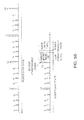
- FIG. 2A is a flowchart illustrating an operating state of a non-contact power supply device according to an exemplary embodiment in the present disclosure
- FIG. 2B is a diagram illustrating signal transmission and signal reception between the non-contact power supply device and the power receiving device in the operating state of FIG. 2A .
- the operating states of the non-contact power supply device may be classified as a power save state S1, a low power state S2, a power transfer state S3, and a fault state S4.
- a short beacon may be broadcast to determine whether or not the power receiving device is in proximity to a power transmitting surface of the non-contact power supply device, and a long beacon may be broadcast to wake-up the communications circuit of the power receiving device.
- the signal level of the short beacon or the long beacon may be varied.
- the short beacon or the long beacon may be output from the power transmitting coil of the non-contact power supply device.
- the non-contact power supply device may transmit a connection request (connection request indicated by reference numeral 2) to the power receiving device, and a variety of parameters (PRU static parameter indicated by reference numeral 3, PTU static parameter indicated by reference numeral 4, and PRU dynamic parameter indicated by reference numeral 5) for transmitting charging power may be then transmitted between the non-contact power supply device and the power receiving device.
- the non-contact power supply device may enter the power transfer state S3.
- the advertisement signal is only received from the power receiving device and the parameters are not transmitted or received, communications failure may be determined and the non-contact power supply device may enter the fault state S4, thereby stopping the operation.
- the non-contact power supply device may request information regarding the charging power necessary for the power receiving device (PRU control indicated by reference numeral 6) and then transmit requested charging power to the power receiving device according to a charging power request or a charging power transmission stop request (PRU dynamic parameter indicated by reference numeral 7) from the power receiving device. If the charging power transmission stop request is made (reference numeral 8), the non-contact power supply device may enter the fault state S4, thereby stopping the operation.
- the signal transmission and reception (reference numerals 1 to 8) in the low power state S2 and the power transfer state S3 described above may be performed between the communications circuit of the non-contact power supply device and the communications circuit of the power receiving device, and the charging power may be transmitted between the power transmitting coil of the non-contact power supply device and the power receiving coil of the power receiving device.
- FIGS. 3A through 3D are diagrams illustrating operations of a non-contact power supply device according to an exemplary embodiment in the present disclosure.
- a non-contact power supply device may broadcast a short beacon (S11), may detect impedance of a power transmitting coil (S12), may broadcast a long beacon if the impedance is varied (S13, S15), and may vary a signal level of the short beacon if the impedance is not varied to thereby broadcast the short beacon (S14).
- the non-contact power supply device may broadcast the short beacon according to a first period.
- the non-contact power supply device may broadcast the long beacon according to a second period different from the first period, additionally.
- a non-contact power supply device according to an exemplary embodiment may independently broadcast a short beacon and a long beacon according to predetermined periods differing from each other.
- the non-contact power supply device may communicate with the power receiving device (S20) and transmit necessary charging power (S30).
- the non-contact power supply device fails to communicate with the power receiving device, it may enter a fault state, thereby stopping the operation.
- the power supply device 100 may include a power transmitting unit 120, a power transmitting coil 130, a detecting unit 140, and a controlling unit 150, and may further include a power supplying unit 110, an oscillating unit 170, and a communicating unit 160.
- the power transmitting unit 120 may transmit a short beacon, a long beacon, and charging power through the power transmitting coil 130, and may vary the signal level of the short beacon or the signal level of the long beacon according to a control of the controlling unit 150 (variations in the signal level of the long beacon will be described below with reference to another exemplary embodiment).
- FIG. 3D illustrates the operation of the non-contact power supply device according to an exemplary embodiment in more detail, which will be described with reference to FIGS. 3A through 3C .
- the power supply device 100 may broadcast a short beacon and a long beacon according to different periods through the power transmitting coil 130.
- the signal level of the short beacon may be varied, while the signal level of the long beacon may be fixed.
- the power transmitting unit 120 may transmit the short beacon through the power transmitting coil 130 according to a predetermined period in order to determine whether or not the power receiving device A is in proximity to the power supply device 100, and may transmit the long beacon according to a period different from the period of the short beacon in order to wake-up a communicating unit a4 of the power receiving device A.
- the detecting unit 140 may detect whether the power receiving device A is in proximity to the power supply device 100 by detecting variations in impedance of the power transmitting coil 130 after the transmission of the short beacon.
- the detecting unit 140 may transmit the detected result to the controlling unit 150, and the controlling unit 150 may vary the signal level of the short beacon until the detected result from the detecting unit 140 corresponds to a state in which the power receiving device A is in proximity to the power supply device 100.
- the controlling unit 150 may vary the signal level of the short beacon by varying a level of power supplied by the power supplying unit 110 to the power transmitting unit 120, and the power transmitting unit 120 may transmit the short beacon to the outside through the power transmitting coil 130 at a carrier frequency provided by the oscillating unit 170.
- the signal levels of the short beacon are set to first to fourth levels s1, s2, s3, and s4, they may be sequentially varied so that the short beacon may have a first level s1, a second level s2, a third level s3, and a fourth level s4 in order.
- the short beacon may be transmitted according to a predetermined period as described above, and for example, in the case in which the signal levels of the short beacon are set to the first to fourth levels s1, s2, s3, and s4, they may be sequentially varied so that the short beacon may have the first level s1, the second level s2, the third level s3, and the fourth level s4 in order according to the predetermined period, may be transmitted in the order of the first level, the second level, the third level, and the fourth level, and then may be repetitively varied and transmitted in the order of the first level, the second level, the third level, and the fourth level.
- the aforementioned signal levels may be varied from a minimum level to a maximum level among the set levels, but may be sequentially varied from a level corresponding to a level when the power receiving device has previously been recognized, in some cases. That is, in a case in which the power receiving device has previously been recognized at the second level, the levels may be repetitively varied and transmitted from the second level to the fourth level, and after the levels are varied from the second level to the fourth level, the levels may be varied and transmitted from the first level to the fourth level.
- a long beacon may be transmitted according to a predetermined period different from that of the short beacon.
- a long beacon may be transmitted independently of the predetermined period, but it may not be transmitted at a timing at which the long beacon having the predetermined period should be transmitted.
- the long beacon may be transmitted independently regardless of the predetermined period.
- the transmitted long beacon may be rectified by a rectifying unit a1 of the power receiving device A, may be converted into power having an appropriate level by a converter a2, and then may be transferred to a communicating unit a4 to thereby wake-up the communicating unit a4. Then, the controlling unit a3 may transmit the advertisement signal through the communicating unit a4, and if the communicating unit 160 receives the advertisement signal from the power receiving device A, it may communicate with the communicating unit a4 of the power receiving device A, and the controlling unit 150 may control operations of the power supplying unit 110 and the power transmitting unit 120 to transmit necessary charging power.
- the power supply device may enter the fault state after the signal transmitting operation in the low power state is repeated three times, and then stop the operation.
- FIGS. 4A through 4D are diagrams illustrating operations of a non-contact power supply device according to another exemplary embodiment in the present disclosure.
- the signal level of a long beacon which is transmitted independently of a predetermined period may be varied (S121, S131, S141).
- the power supply device may communicate with the power receiving device (S21) and then transmit charging power (S31), and if the power supply device fails to communicate with the power receiving device, the power supply device may enter a fault state (S41).
- the non-contact power supply device may transmit the long beacon prior to a timing at which the long beacon having the predetermined period is to be transmitted in order to wake-up the communications circuit of the power receiving device when, by broadcasting the short beacon, the impedance of the power transmitting coil is varied to a preset level or more,.
- the signal level of the long beacon may be varied.
- the signal levels of the aforementioned long beacon may be sequentially increased from a first level L1 to a fourth level L4.
- the signal levels may be sequentially increased within a set time from a level corresponding to a level when the advertisement signal has previously been received from the power receiving device to a maximum level.
- the signal levels of the long beacon may be continuously varied as illustrated, without a predetermined time interval.
- the signal levels of the short beacon may be fixed as illustrated in FIG. 4B or may be varied as illustrated in FIG. 4C .
- the signal levels of the long beacon having the predetermined period may be fixed as illustrated in FIG. 4B and 4C , or may be varied as illustrated in FIG. 4D .
- FIGS. 5A through 5C are diagrams illustrating operations of a non-contact power supply device according to another exemplary embodiment in the present disclosure.
- the power receiving device may not be recognized. That is, in a case in which the size of the power receiving coil such as a power receiving coil included in a wearable device as illustrated in FIG. 1C , is relatively small, variations in impedance of the power receiving coil is small even when the power receiving device is accurately positioned at the center of the power transmitting surface, and thus, the power receiving device may not be recognized.
- the short beacon may be transmitted according to a predetermined period in actual operation
- the communications circuit of the power receiving device is woken-up by a long beacon which is transmitted according to a predetermined period and an advertisement signal is received (S112, S122, S132)
- the power supply device may communicate with the power receiving device (S22) and then transmit charging power (S32).
- the power supply device fails to communicate with the power receiving device, it may enter a fault state (S42).
- the signal levels of the long beacon which is transmitted according to the predetermined period may be varied depending on whether or not the advertisement signal has been received.
- the signal levels of the long beacon which is transmitted according to the predetermined period may be varied depending on whether or not the advertisement signal has been received. If the advertisement signal is received from the communications circuit of the power receiving device, the power supply device may communicate with the power receiving device and then transmit charging power.
- the signal levels of the long beacon may be sequentially varied from a minimum level to a maximum level among the set signal levels as illustrated in FIG. 4B , and may be sequentially varied from a level corresponding to a level when the advertisement signal has previously been received from the power receiving device to the maximum level, in some cases.
- the signal levels of the long beacon are set to the first to fourth levels L1, L2, L3, and L4, they may be sequentially varied so that the long beacon may have the first level L1, the second level L2, the third level L3, and the fourth level L4 according to the predetermined period, may be transmitted in the order of the first level, the second level, the third level, and the fourth level, and then may be repetitively varied and transmitted in the order of the first level, the second level, the third level, and the fourth level.
- the aforementioned signal levels may be varied from the minimum level to the maximum level among the set levels, but may be sequentially varied from a level corresponding to a level when the advertisement signal has previously been received, in some cases. That is, in the case in which the advertisement signal has previously been received at the second level, the levels may be repetitively varied and transmitted from the second level to the fourth level, and after the levels are varied from the second level to the fourth level, the levels may be varied and transmitted from the first level to the fourth level.
- FIGS. 6A and 6B are diagrams illustrating examples of a short beacon or a long beacon output from the power supply device according to exemplary embodiments of the present disclosure.
- the signal levels of the short beacon or the long beacon may be randomly varied.
- the power receiving device may be properly recognized or the communications circuit of the power receiving device may be woken-up even in the case in which a coupling coefficient between the non-contact power supply device and the power receiving device is low, and power loss may be reduced by outputting a short beacon or a long beacon having a relatively low level in the case in which the coupling coefficient between the non-contact power supply device and the power receiving device is high.
Landscapes
- Engineering & Computer Science (AREA)
- Power Engineering (AREA)
- Computer Networks & Wireless Communication (AREA)
- Charge And Discharge Circuits For Batteries Or The Like (AREA)
- Signal Processing (AREA)
Abstract
Description
- This application claims the priority and benefit of Korean Patent Application Nos.
10-2013-0141740 filed on November 20, 2013 10-2014-0078486 filed on June 25, 2014 10-2014-0096825 filed on July 29, 2014 10-2014-0153387 filed on November 6, 2014 - The present disclosure relates to a non-contact power supply device and a non-contact power supply method in which power is transmitted in a contactless manner.
- In order to supply power to an electronic device, a power supply device for transferring power from an external power source to the electronic device is required.
- In general, a wired power supply device, directly connected to an electronic device via a connector, or the like, to supply power to a battery included in the electronic device, is currently in widespread use. Alternatively, as disclosed in the following related art document, power may be supplied to the battery provided in the electronic device in a contactless manner through a magnetic induction effect or a magnetic resonance effect.
- Meanwhile, as disclosed in the following related art document, a non-contact power supply device may transmit a short beacon to determine whether or not a power receiving device which receives power in a contactless manner is in proximity to a charging surface of the power supply device. Here, the non-contact power supply device may not properly recognize the power receiving device in the vicinity thereof, due to reliance on a coupling coefficient between a coil of the charging surface of the non-contact power supply device and a coil of the power receiving device. In addition, the non-contact power supply device may transmit a relatively long beacon to wake-up a communications circuit of the power receiving device so as to perform a normal charging operation. In such a case, the communications circuit of the power receiving device may not be woken-up, due to problems with the coupling coefficient between the coil of the charging surface and the coil of the power receiving device.
- (Patent Document 1) Korean Patent Laid-Open Publication No.
10-2011-0009227 - An aspect of the present disclosure may provide a non-contact power supply device and a non-contact power supply method in which signal levels of a short beacon or a long beacon are varied.
- According to an aspect of the present disclosure, there may be provided a non-contact power supply device and a non-contact power supply method in which a short beacon is transmitted to recognize a power receiving device, a long beacon is transmitted to wake-up a communications circuit of the power receiving device, and charging power is transmitted in a contactless manner, wherein at least one of signal levels of the short beacon and signal levels of the long beacon is varied.
- The above and other aspects, features and advantages of the present disclosure will be more clearly understood from the following detailed description taken in conjunction with the accompanying drawings, in which:
-
FIGS. 1A through 1C are exemplary diagrams illustrating a non-contact power supply device and a power receiving device; -
FIG. 2A is a flowchart illustrating an operation of a non-contact power supply device according to an exemplary embodiment in the present disclosure; -
FIG. 2B is an exemplary diagram illustrating signal transmission and signal reception between the non-contact power supply device and the power receiving device, in the operation illustrated inFIG. 2A ; -
FIGS. 3A through 3D are diagrams illustrating operations of a non-contact power supply device according to an exemplary embodiment in the present disclosure; -
FIGS. 4A through 4D are diagrams illustrating operations of a non-contact power supply device according to another exemplary embodiment in the present disclosure; -
FIGS. 5A through 5C are diagrams illustrating operations of a non-contact power supply device according to another exemplary embodiment in the present disclosure; and -
FIGS. 6A and 6B are diagrams illustrating examples of a short beacon or a long beacon output from a non-contact power supply device according to an exemplary embodiment in the present disclosure. - Hereinafter, embodiments of the present disclosure will be described in detail with reference to the accompanying drawings.
- The disclosure may, however, be embodied in many different forms and should not be construed as being limited to the embodiments set forth herein. Rather, these embodiments are provided so that this disclosure will be thorough and complete, and will fully convey the scope of the disclosure to those skilled in the art.
- In the drawings, the shapes and dimensions of elements may be exaggerated for clarity, and the same reference numerals will be used throughout to designate the same or like elements.
-
FIGS. 1A through 1C are diagrams illustrating a non-contact power supply device and a power receiving device. - Referring to
FIG. 1A , apower supply device 100 according to an exemplary embodiment may transmit a short beacon, a long beacon, and charging power in a contactless manner (here, the contactless manner may refer to a process in which power is transmitted from a transmitting side to a receiving side without a direct connection between conductors of the transmitting side and the receiving side, in other words, via a non-contact transmission, a wireless transmission, or the like). Thepower supply device 100 according to an exemplary embodiment may transmit the short beacon, the long beacon, and the charging power through a power transmittingcoil 130. - In a case in which a power receiving device A is in proximity to a surface of the
power supply device 100, a coupling coefficient between a power receiving coil (not shown) of the power receiving device A and a power transmittingcoil 130 may be reduced, as a distance of the power receiving device A from the center of thepower transmitting coil 130 having a predetermined number of turns is increased, and thus, thepower supply device 100 may not properly recognize the power receiving device A or may not wake up a communications circuit of the power receiving device A, even when thepower supply device 100 transmits a short beacon or a long beacon having a predetermined signal level. - Referring to
FIG. 1B , in a case in which the power receiving device A is positioned to be in proximity to the center of thepower transmitting coil 130, the coupling coefficient between the power receiving coil (not shown) of the power receiving device A and thepower transmitting coil 130 is relatively high, and thus, thepower supply device 100 may recognize the power receiving device A or wake-up the communications circuit of the power receiving device A by using a short beacon or a long beacon having a low signal level. However, the transmission of a short beacon or a long beacon having a signal level equal to or higher than a predetermined signal level may result in unnecessary power consumption. Even in a case in which the power receiving device A is positioned to be in proximity to the center of thepower transmitting coil 130, the coupling coefficient therebetween may be low due to a compatibility problem between the power receiving device A and thepower supply device 100. This can be seen as a situation the equivalent of that ofFIG. 1A . - Referring to
FIG. 1C , in a case in which a power receiving device B is a wearable device such as a smartwatch, it has a relatively small power receiving coil b, and thus, thepower supply device 100 may not properly recognize the power receiving device B even when the power receiving device B is positioned to be in proximity to the center of thepower transmitting coil 130. -
FIG. 2A is a flowchart illustrating an operating state of a non-contact power supply device according to an exemplary embodiment in the present disclosure, andFIG. 2B is a diagram illustrating signal transmission and signal reception between the non-contact power supply device and the power receiving device in the operating state ofFIG. 2A . - Referring to
FIGS. 2A and2B , the operating states of the non-contact power supply device according to an exemplary embodiment may be classified as a power save state S1, a low power state S2, a power transfer state S3, and a fault state S4. - In the power save state S1, a short beacon may be broadcast to determine whether or not the power receiving device is in proximity to a power transmitting surface of the non-contact power supply device, and a long beacon may be broadcast to wake-up the communications circuit of the power receiving device.
- In this case, the signal level of the short beacon or the long beacon may be varied.
- The short beacon or the long beacon may be output from the power transmitting coil of the non-contact power supply device.
- In the low power state S2, in a case in which the non-contact power supply device receives an advertisement signal (PRU advertisement indicated by reference numeral ①) from the power receiving device, the non-contact power supply device may transmit a connection request (connection request indicated by reference numeral ②) to the power receiving device, and a variety of parameters (PRU static parameter indicated by
reference numeral ③, PTU static parameter indicated byreference numeral ④, and PRU dynamic parameter indicated by reference numeral ⑤) for transmitting charging power may be then transmitted between the non-contact power supply device and the power receiving device. - In a case in which the transmission of the parameters between the non-contact power supply device and the power receiving device is completed, the non-contact power supply device may enter the power transfer state S3. In a case in which the advertisement signal is only received from the power receiving device and the parameters are not transmitted or received, communications failure may be determined and the non-contact power supply device may enter the fault state S4, thereby stopping the operation.
- In the power transfer state S3, the non-contact power supply device may request information regarding the charging power necessary for the power receiving device (PRU control indicated by reference numeral ⑥) and then transmit requested charging power to the power receiving device according to a charging power request or a charging power transmission stop request (PRU dynamic parameter indicated by reference numeral ⑦) from the power receiving device. If the charging power transmission stop request is made (reference numeral ⑧), the non-contact power supply device may enter the fault state S4, thereby stopping the operation.
- The signal transmission and reception (
reference numerals ① to ⑧) in the low power state S2 and the power transfer state S3 described above may be performed between the communications circuit of the non-contact power supply device and the communications circuit of the power receiving device, and the charging power may be transmitted between the power transmitting coil of the non-contact power supply device and the power receiving coil of the power receiving device. -
FIGS. 3A through 3D are diagrams illustrating operations of a non-contact power supply device according to an exemplary embodiment in the present disclosure. - Referring to
FIG. 3A , a non-contact power supply device according to an exemplary embodiment may broadcast a short beacon (S11), may detect impedance of a power transmitting coil (S12), may broadcast a long beacon if the impedance is varied (S13, S15), and may vary a signal level of the short beacon if the impedance is not varied to thereby broadcast the short beacon (S14). The non-contact power supply device according to an exemplary embodiment may broadcast the short beacon according to a first period. - In the step S11, the non-contact power supply device according to an exemplary embodiment may broadcast the long beacon according to a second period different from the first period, additionally. In other word, a non-contact power supply device according to an exemplary embodiment may independently broadcast a short beacon and a long beacon according to predetermined periods differing from each other.
- If a communications circuit of a power receiving device is woken-up by the transmitted long beacon and the non-contact power supply device receives an advertisement signal from the power receiving device (S16), the non-contact power supply device may communicate with the power receiving device (S20) and transmit necessary charging power (S30).
- If the non-contact power supply device fails to communicate with the power receiving device, it may enter a fault state, thereby stopping the operation.
- Referring to
FIGS. 3B and3C , thepower supply device 100 according to an exemplary embodiment may include apower transmitting unit 120, apower transmitting coil 130, a detectingunit 140, and a controllingunit 150, and may further include apower supplying unit 110, anoscillating unit 170, and a communicatingunit 160. - The
power transmitting unit 120 may transmit a short beacon, a long beacon, and charging power through thepower transmitting coil 130, and may vary the signal level of the short beacon or the signal level of the long beacon according to a control of the controlling unit 150 (variations in the signal level of the long beacon will be described below with reference to another exemplary embodiment). - Meanwhile,
FIG. 3D illustrates the operation of the non-contact power supply device according to an exemplary embodiment in more detail, which will be described with reference toFIGS. 3A through 3C . - The
power supply device 100 according to an exemplary embodiment may broadcast a short beacon and a long beacon according to different periods through thepower transmitting coil 130. - For example, the signal level of the short beacon may be varied, while the signal level of the long beacon may be fixed.
- That is, the
power transmitting unit 120 may transmit the short beacon through thepower transmitting coil 130 according to a predetermined period in order to determine whether or not the power receiving device A is in proximity to thepower supply device 100, and may transmit the long beacon according to a period different from the period of the short beacon in order to wake-up a communicating unit a4 of the power receiving device A. - In a case in which the short beacon is induced to the power receiving coil of the power receiving device A, impedance of the
power transmitting coil 130 is varied. Therefore, the detectingunit 140 may detect whether the power receiving device A is in proximity to thepower supply device 100 by detecting variations in impedance of thepower transmitting coil 130 after the transmission of the short beacon. The detectingunit 140 may transmit the detected result to the controllingunit 150, and the controllingunit 150 may vary the signal level of the short beacon until the detected result from the detectingunit 140 corresponds to a state in which the power receiving device A is in proximity to thepower supply device 100. - In this case, the controlling
unit 150 may vary the signal level of the short beacon by varying a level of power supplied by thepower supplying unit 110 to thepower transmitting unit 120, and thepower transmitting unit 120 may transmit the short beacon to the outside through thepower transmitting coil 130 at a carrier frequency provided by theoscillating unit 170. - As illustrated, for example, in a case in which the signal levels of the short beacon are set to first to fourth levels s1, s2, s3, and s4, they may be sequentially varied so that the short beacon may have a first level s1, a second level s2, a third level s3, and a fourth level s4 in order. The short beacon may be transmitted according to a predetermined period as described above, and for example, in the case in which the signal levels of the short beacon are set to the first to fourth levels s1, s2, s3, and s4, they may be sequentially varied so that the short beacon may have the first level s1, the second level s2, the third level s3, and the fourth level s4 in order according to the predetermined period, may be transmitted in the order of the first level, the second level, the third level, and the fourth level, and then may be repetitively varied and transmitted in the order of the first level, the second level, the third level, and the fourth level.
- The aforementioned signal levels may be varied from a minimum level to a maximum level among the set levels, but may be sequentially varied from a level corresponding to a level when the power receiving device has previously been recognized, in some cases. That is, in a case in which the power receiving device has previously been recognized at the second level, the levels may be repetitively varied and transmitted from the second level to the fourth level, and after the levels are varied from the second level to the fourth level, the levels may be varied and transmitted from the first level to the fourth level.
- Meanwhile, as described above, a long beacon may be transmitted according to a predetermined period different from that of the short beacon. Here, if the impedance of the
power transmitting coil 130 is varied after the transmission of the short beacon and it is determined that the power receiving device A is in proximity to thepower supply device 100, a long beacon may be transmitted independently of the predetermined period, but it may not be transmitted at a timing at which the long beacon having the predetermined period should be transmitted. - For example, if the short beacon having the third level is transmitted and it is determined that the power receiving device A is in proximity to the
power supply device 100, the long beacon may be transmitted independently regardless of the predetermined period. - The transmitted long beacon may be rectified by a rectifying unit a1 of the power receiving device A, may be converted into power having an appropriate level by a converter a2, and then may be transferred to a communicating unit a4 to thereby wake-up the communicating unit a4. Then, the controlling unit a3 may transmit the advertisement signal through the communicating unit a4, and if the communicating
unit 160 receives the advertisement signal from the power receiving device A, it may communicate with the communicating unit a4 of the power receiving device A, and the controllingunit 150 may control operations of thepower supplying unit 110 and thepower transmitting unit 120 to transmit necessary charging power. - If the communicating
unit 160 fails to communicate with the power receiving device A after receiving the advertisement signal, the power supply device may enter the fault state after the signal transmitting operation in the low power state is repeated three times, and then stop the operation. -
FIGS. 4A through 4D are diagrams illustrating operations of a non-contact power supply device according to another exemplary embodiment in the present disclosure. - Referring to
FIG. 4A , if a short beacon is transmitted and it is then determined that the power receiving device is in proximity to the power supply device (S111), the signal level of a long beacon which is transmitted independently of a predetermined period may be varied (S121, S131, S141). - Next, if an advertisement signal is received from the power receiving device, the power supply device may communicate with the power receiving device (S21) and then transmit charging power (S31), and if the power supply device fails to communicate with the power receiving device, the power supply device may enter a fault state (S41).
- More particularly, the non-contact power supply device according to an exemplary embodiment may transmit the long beacon prior to a timing at which the long beacon having the predetermined period is to be transmitted in order to wake-up the communications circuit of the power receiving device when, by broadcasting the short beacon, the impedance of the power transmitting coil is varied to a preset level or more,.
- In this case, if the advertisement signal is not received from the communications circuit of the power receiving device by the long beacon having a predetermined level, the signal level of the long beacon may be varied.
- For example, as illustrated in
FIG. 4B , in a case in which the signal levels of the aforementioned long beacon are set to first to fourth levels (L1, L2, L3, L4), the signal levels of the long beacon may be sequentially increased from a first level L1 to a fourth level L4. In some cases, the signal levels may be sequentially increased within a set time from a level corresponding to a level when the advertisement signal has previously been received from the power receiving device to a maximum level. - The signal levels of the long beacon may be continuously varied as illustrated, without a predetermined time interval.
- Meanwhile, in exemplary embodiments, the signal levels of the short beacon may be fixed as illustrated in
FIG. 4B or may be varied as illustrated inFIG. 4C . - In exemplary embodiments, the signal levels of the long beacon having the predetermined period may be fixed as illustrated in
FIG. 4B and4C , or may be varied as illustrated inFIG. 4D . -
FIGS. 5A through 5C are diagrams illustrating operations of a non-contact power supply device according to another exemplary embodiment in the present disclosure. - Referring to
FIG. 5A , even in a case in which a short beacon is transmitted, the power receiving device may not be recognized. That is, in a case in which the size of the power receiving coil such as a power receiving coil included in a wearable device as illustrated inFIG. 1C , is relatively small, variations in impedance of the power receiving coil is small even when the power receiving device is accurately positioned at the center of the power transmitting surface, and thus, the power receiving device may not be recognized. - In this case, regardless of a recognition fail of the power receiving device by the short beacon (although the transmission of the short beacon is omitted in the drawing, the short beacon may be transmitted according to a predetermined period in actual operation), if the communications circuit of the power receiving device is woken-up by a long beacon which is transmitted according to a predetermined period and an advertisement signal is received (S112, S122, S132), the power supply device may communicate with the power receiving device (S22) and then transmit charging power (S32). Similarly, if the power supply device fails to communicate with the power receiving device, it may enter a fault state (S42).
- For example, the signal levels of the long beacon which is transmitted according to the predetermined period may be varied depending on whether or not the advertisement signal has been received.
- As illustrated in
FIGS. 5B and5C , if the power receiving device is not recognized due to small variations in impedance even when the signal levels of the short beacon are fixed or varied, the signal levels of the long beacon which is transmitted according to the predetermined period may be varied depending on whether or not the advertisement signal has been received. If the advertisement signal is received from the communications circuit of the power receiving device, the power supply device may communicate with the power receiving device and then transmit charging power. The signal levels of the long beacon may be sequentially varied from a minimum level to a maximum level among the set signal levels as illustrated inFIG. 4B , and may be sequentially varied from a level corresponding to a level when the advertisement signal has previously been received from the power receiving device to the maximum level, in some cases. - For example, in the case in which the signal levels of the long beacon are set to the first to fourth levels L1, L2, L3, and L4, they may be sequentially varied so that the long beacon may have the first level L1, the second level L2, the third level L3, and the fourth level L4 according to the predetermined period, may be transmitted in the order of the first level, the second level, the third level, and the fourth level, and then may be repetitively varied and transmitted in the order of the first level, the second level, the third level, and the fourth level.
- The aforementioned signal levels may be varied from the minimum level to the maximum level among the set levels, but may be sequentially varied from a level corresponding to a level when the advertisement signal has previously been received, in some cases. That is, in the case in which the advertisement signal has previously been received at the second level, the levels may be repetitively varied and transmitted from the second level to the fourth level, and after the levels are varied from the second level to the fourth level, the levels may be varied and transmitted from the first level to the fourth level.
-
FIGS. 6A and 6B are diagrams illustrating examples of a short beacon or a long beacon output from the power supply device according to exemplary embodiments of the present disclosure. - Referring to
FIGS. 6A and 6B , in exemplary embodiments, the signal levels of the short beacon or the long beacon may be randomly varied. - As set forth above, according to exemplary embodiments of the present disclosure, the power receiving device may be properly recognized or the communications circuit of the power receiving device may be woken-up even in the case in which a coupling coefficient between the non-contact power supply device and the power receiving device is low, and power loss may be reduced by outputting a short beacon or a long beacon having a relatively low level in the case in which the coupling coefficient between the non-contact power supply device and the power receiving device is high.
- While exemplary embodiments have been shown and described above, it will be apparent to those skilled in the art that modifications and variations could be made without departing from the scope of the present invention as defined by the appended claims.
Claims (15)
- A non-contact power supply device transmitting a short beacon according to a first period to recognize a power receiving device and transmitting a charging power in a contactless manner, the non-contact power supply device comprising:a power transmitting unit controlling the transmission of the short beacon and the charging power;a power transmitting coil transmitting the short beacon and the charging power in a contactless manner according to the controlling of the power transmitting unit; anda controlling unit controlling variations in signal levels of the short beacon.
- The non-contact power supply device of claim 1, wherein the controlling unit controls the signal levels of the short beacon by controlling a voltage level of input power applied to the power transmitting unit.
- The non-contact power supply device of claim 1, further comprising a detecting unit detecting variations in impedance of the power transmitting coil.
- The non-contact power supply device of claim 3, wherein the controlling unit controls the signal levels of the short beacon according to a detection result from the detecting unit.
- The non-contact power supply device of claim 1, wherein the controlling unit sequentially increases the signal levels of the short beacon.
- The non-contact power supply device of claim 5, wherein the controlling unit sequentially increases the signal levels of the short beacon from a minimum signal level to a maximum signal level among a plurality of set signal levels.
- The non-contact power supply device of claim 5, wherein the controlling unit sequentially increases the signal levels of the short beacon from a signal level corresponding to a signal level when the power receiving device has previously been recognized to a maximum signal level among a plurality of set signal levels.
- The non-contact power supply device of claim 1, wherein the controlling unit controls transmission of a long beacon for waking-up a communications circuit of the power receiving device which is transmitted according to a second period different from the first period, and
signal levels of the long beacon are fixed or varied. - The non-contact power supply device of claim 1, wherein the controlling unit controls signal levels of a long beacon for waking-up a communications circuit of the power receiving device to be sequentially varied within a set time until an advertisement signal is received from the power receiving device when the power receiving device has been recognized by the transmission of the short beacon.
- A non-contact power supply device transmitting a long beacon according to a period to wake-up a communications circuit of a power receiving device and transmitting a charging power in a contactless manner, the non-contact power supply device comprising:a power transmitting unit controlling the transmission of the long beacon and the charging power;a power transmitting coil transmitting the long beacon and the charging power in a contactless manner according to the controlling of the power transmitting unit; anda controlling unit controlling variations in signal levels of the long beacon.
- The non-contact power supply device of claim 10, wherein the controlling unit controls the signal levels of the long beacon by controlling a voltage level of input power applied to the power transmitting unit.
- The non-contact power supply device of claim 10, wherein the controlling unit sequentially increases the signal levels of the long beacon from a minimum signal level to a maximum signal level among a plurality of set signal levels.
- The non-contact power supply device of claim 10, wherein the controlling unit sequentially increases the signal levels of the long beacon from a signal level corresponding to a signal level when the communications circuit of the power receiving device has previously been woken-up to a maximum signal level among a plurality of set signal levels.
- The non-contact power supply device of claim 10, wherein the controlling unit controls transmission of a short beacon for recognizing the power receiving device, and
signal levels of the short beacon are fixed or varied. - The non-contact power supply device of claim 10, wherein the controlling unit controls signal levels of a long beacon in a next period depending on whether or not an advertisement signal has been received from the power receiving device.
Applications Claiming Priority (4)
| Application Number | Priority Date | Filing Date | Title |
|---|---|---|---|
| KR20130141740 | 2013-11-20 | ||
| KR20140078486 | 2014-06-25 | ||
| KR1020140096825A KR20150057951A (en) | 2013-11-20 | 2014-07-29 | Non-contact type power supplying apparatus and non-contact type power supplying method |
| KR1020140153387A KR20150057984A (en) | 2013-11-20 | 2014-11-06 | Non-contact type power supplying apparatus and non-contact type power supplying method |
Publications (1)
| Publication Number | Publication Date |
|---|---|
| EP2884622A1 true EP2884622A1 (en) | 2015-06-17 |
Family
ID=51904923
Family Applications (1)
| Application Number | Title | Priority Date | Filing Date |
|---|---|---|---|
| EP14275240.1A Withdrawn EP2884622A1 (en) | 2013-11-20 | 2014-11-19 | Non-contact power supply device and non-contact power supply method |
Country Status (3)
| Country | Link |
|---|---|
| US (1) | US10454303B2 (en) |
| EP (1) | EP2884622A1 (en) |
| CN (1) | CN104659887B (en) |
Cited By (1)
| Publication number | Priority date | Publication date | Assignee | Title |
|---|---|---|---|---|
| EP3493366A4 (en) * | 2016-07-28 | 2020-01-01 | LG Innotek Co., Ltd. | Location checking method and apparatus for wireless power receiver |
Families Citing this family (14)
| Publication number | Priority date | Publication date | Assignee | Title |
|---|---|---|---|---|
| US10135284B2 (en) * | 2014-04-11 | 2018-11-20 | Sk Planet Co., Ltd. | Wireless charging equipment for providing charging service to selective users |
| WO2016099032A1 (en) | 2014-12-16 | 2016-06-23 | 주식회사 한림포스텍 | Apparatus and method for controlling power transmission coverage of wireless power transmission network |
| KR20160051497A (en) * | 2014-11-03 | 2016-05-11 | 주식회사 한림포스텍 | Method and apparutus for controlling a power transmission coverage of wireless power transmission network |
| US9705569B2 (en) | 2015-05-26 | 2017-07-11 | Samsung Electro-Mechanics Co., Ltd. | Wireless power transmitter and method for controlling the same |
| US20160373166A1 (en) * | 2015-06-17 | 2016-12-22 | Intel Corporation | Proximity sensor for deep sleep wakeup of wireless charger |
| US20160380467A1 (en) * | 2015-06-26 | 2016-12-29 | Lei Shao | Managing the output power of a wireless charger |
| KR20170014879A (en) * | 2015-07-31 | 2017-02-08 | 삼성전기주식회사 | Apparatus and method for transmiting power wirelessly |
| JP6555010B2 (en) * | 2015-08-25 | 2019-08-07 | 船井電機株式会社 | Power supply device |
| US10153644B2 (en) * | 2015-11-13 | 2018-12-11 | X Development Llc | Delivering and negotiating wireless power delivery in a multi-receiver system |
| US10317963B1 (en) * | 2015-11-13 | 2019-06-11 | X Development Llc | Modular mechanism enabled by mid-range wireless power |
| CN107658999A (en) * | 2016-07-26 | 2018-02-02 | 宁波微鹅电子科技有限公司 | A kind of non-contact electric energy transmission device and its control method |
| US10944291B2 (en) | 2016-10-12 | 2021-03-09 | Wits Co., Ltd. | Wireless power transmitter |
| US20180152050A1 (en) * | 2016-11-29 | 2018-05-31 | Samsung Electro-Mechanics Co., Ltd. | Apparatus for transmitting power wirelessly |
| CN107482798B (en) * | 2017-08-03 | 2021-03-23 | 青岛众海汇智能源科技有限责任公司 | Wireless power supply system standby method, wireless power supply system, transmitter and receiver |
Citations (7)
| Publication number | Priority date | Publication date | Assignee | Title |
|---|---|---|---|---|
| US20100270867A1 (en) * | 2009-04-22 | 2010-10-28 | Panasonic Electric Works Co., Ltd. | Non-contact power supply system |
| KR20110009227A (en) | 2008-05-13 | 2011-01-27 | 퀄컴 인코포레이티드 | Transmit power control for a wireless charging system |
| US20120040613A1 (en) * | 2009-05-13 | 2012-02-16 | Canon Kabushiki Kaisha | Power-supplying device, control method of the same, and power supply system |
| US20120049644A1 (en) * | 2010-08-26 | 2012-03-01 | Jin Sung Choi | Resonance power transmission system based on power transmission efficiency |
| US20120223589A1 (en) * | 2011-03-01 | 2012-09-06 | Qualcomm Incorporated | Waking up a wireless power transmitter from beacon mode |
| US20130154558A1 (en) * | 2011-12-15 | 2013-06-20 | Samsung Electronics Co., Ltd. | Method and apparatus for transmitting wireless power |
| WO2013121757A1 (en) * | 2012-02-13 | 2013-08-22 | パナソニック株式会社 | Power supply device, power receiving device, charging system, and obstacle detection method |
Family Cites Families (3)
| Publication number | Priority date | Publication date | Assignee | Title |
|---|---|---|---|---|
| KR20120134029A (en) | 2011-05-31 | 2012-12-11 | 삼성전자주식회사 | Wireless power transmission and charging system, and communication method of wireless power transmission and charging system |
| US20120311363A1 (en) | 2011-05-31 | 2012-12-06 | Nam Yun Kim | Wireless power transmission and charging system, and communication method of wireless power transmission and charging system |
| TWI587597B (en) | 2012-02-17 | 2017-06-11 | Lg伊諾特股份有限公司 | Wireless power transmitter, wireless power receiver, and power transmission method of wireless power transmitting system |
-
2014
- 2014-11-19 EP EP14275240.1A patent/EP2884622A1/en not_active Withdrawn
- 2014-11-19 US US14/547,449 patent/US10454303B2/en active Active
- 2014-11-20 CN CN201410669963.0A patent/CN104659887B/en active Active
Patent Citations (8)
| Publication number | Priority date | Publication date | Assignee | Title |
|---|---|---|---|---|
| KR20110009227A (en) | 2008-05-13 | 2011-01-27 | 퀄컴 인코포레이티드 | Transmit power control for a wireless charging system |
| US20100270867A1 (en) * | 2009-04-22 | 2010-10-28 | Panasonic Electric Works Co., Ltd. | Non-contact power supply system |
| US20120040613A1 (en) * | 2009-05-13 | 2012-02-16 | Canon Kabushiki Kaisha | Power-supplying device, control method of the same, and power supply system |
| US20120049644A1 (en) * | 2010-08-26 | 2012-03-01 | Jin Sung Choi | Resonance power transmission system based on power transmission efficiency |
| US20120223589A1 (en) * | 2011-03-01 | 2012-09-06 | Qualcomm Incorporated | Waking up a wireless power transmitter from beacon mode |
| US20130154558A1 (en) * | 2011-12-15 | 2013-06-20 | Samsung Electronics Co., Ltd. | Method and apparatus for transmitting wireless power |
| WO2013121757A1 (en) * | 2012-02-13 | 2013-08-22 | パナソニック株式会社 | Power supply device, power receiving device, charging system, and obstacle detection method |
| EP2816706A1 (en) * | 2012-02-13 | 2014-12-24 | Panasonic Corporation | Power supply device, power receiving device, charging system, and obstacle detection method |
Cited By (1)
| Publication number | Priority date | Publication date | Assignee | Title |
|---|---|---|---|---|
| EP3493366A4 (en) * | 2016-07-28 | 2020-01-01 | LG Innotek Co., Ltd. | Location checking method and apparatus for wireless power receiver |
Also Published As
| Publication number | Publication date |
|---|---|
| US10454303B2 (en) | 2019-10-22 |
| CN104659887A (en) | 2015-05-27 |
| US20150137748A1 (en) | 2015-05-21 |
| CN104659887B (en) | 2019-04-26 |
Similar Documents
| Publication | Publication Date | Title |
|---|---|---|
| EP2884622A1 (en) | Non-contact power supply device and non-contact power supply method | |
| US11139859B2 (en) | Wireless inductive power transfer | |
| US9769869B2 (en) | Non-contact type power supply apparatus and non-contact type power supply method | |
| EP2919357B1 (en) | Wireless power transmisson apparatus and wireless power transmisson method | |
| TWI664789B (en) | Wireless load modulation | |
| US20130024046A1 (en) | Power transmission controller, power reception controller, power transmission system, and data communication method of power transmission system | |
| US8922525B2 (en) | Touch-controlled electronic device and method for reducing wireless signal interference to touch sensing function | |
| US10170933B2 (en) | Non-contact type power supplying apparatus and non-contact type power supplying method | |
| US20140232199A1 (en) | Apparatus and method for detecting foreign object in wireless power transmitting system | |
| CN112234720B (en) | Contactless power supply device | |
| KR20150050142A (en) | Electronic device | |
| KR20150057984A (en) | Non-contact type power supplying apparatus and non-contact type power supplying method | |
| KR20120052517A (en) | Wireless power transmission method, wireless power receiving method, wireless power transmission apparatus and wireless power receiving apparatus | |
| JP6778005B2 (en) | Power transmission equipment, its control method, and programs | |
| KR102266079B1 (en) | Apparatus and method for transmiting power wirelessly | |
| US11641134B2 (en) | Wireless charging device and a method for detecting a receiver device | |
| US20180349655A1 (en) | Wireless communication apparatus, host terminal, and wireless communication system | |
| KR20150054634A (en) | Non-contact type power supplying apparatus and non-contact type power supplying method | |
| EP3242374B1 (en) | Wireless power transmission device and wireless charging system comprising same | |
| KR20190036436A (en) | Mobile terminal, communication module and control method of mobile terminal | |
| JP2017060233A (en) | Power reception device, power reception device control method, and program | |
| CN104122546A (en) | Multi-coil array type wireless power supply system receiving end positioning method and system | |
| TW202027379A (en) | Method for transmitting wireless charging signal and wireless power transmitting device therefor | |
| KR20160046891A (en) | Method and system for regulating contactless transformer | |
| KR20150030018A (en) | Wireless power transmission and reception system |
Legal Events
| Date | Code | Title | Description |
|---|---|---|---|
| PUAI | Public reference made under article 153(3) epc to a published international application that has entered the european phase |
Free format text: ORIGINAL CODE: 0009012 |
|
| 17P | Request for examination filed |
Effective date: 20141119 |
|
| AK | Designated contracting states |
Kind code of ref document: A1 Designated state(s): AL AT BE BG CH CY CZ DE DK EE ES FI FR GB GR HR HU IE IS IT LI LT LU LV MC MK MT NL NO PL PT RO RS SE SI SK SM TR |
|
| AX | Request for extension of the european patent |
Extension state: BA ME |
|
| STAA | Information on the status of an ep patent application or granted ep patent |
Free format text: STATUS: REQUEST FOR EXAMINATION WAS MADE |
|
| R17P | Request for examination filed (corrected) |
Effective date: 20151202 |
|
| RBV | Designated contracting states (corrected) |
Designated state(s): AL AT BE BG CH CY CZ DE DK EE ES FI FR GB GR HR HU IE IS IT LI LT LU LV MC MK MT NL NO PL PT RO RS SE SI SK SM TR |
|
| RAP1 | Party data changed (applicant data changed or rights of an application transferred) |
Owner name: WITS CO., LTD. |
|
| STAA | Information on the status of an ep patent application or granted ep patent |
Free format text: STATUS: EXAMINATION IS IN PROGRESS |
|
| 17Q | First examination report despatched |
Effective date: 20210305 |
|
| STAA | Information on the status of an ep patent application or granted ep patent |
Free format text: STATUS: EXAMINATION IS IN PROGRESS |
|
| STAA | Information on the status of an ep patent application or granted ep patent |
Free format text: STATUS: THE APPLICATION IS DEEMED TO BE WITHDRAWN |
|
| 18D | Application deemed to be withdrawn |
Effective date: 20220601 |