EP2884361B1 - Verfahren zum Betrieb eines Bewegungssteuerungssystems und nach dem Verfahren arbeitendes Bewegungssteuerungssystem sowie Computerprogramm zur Implementierung des Verfahrens - Google Patents
Verfahren zum Betrieb eines Bewegungssteuerungssystems und nach dem Verfahren arbeitendes Bewegungssteuerungssystem sowie Computerprogramm zur Implementierung des Verfahrens Download PDFInfo
- Publication number
- EP2884361B1 EP2884361B1 EP13196906.5A EP13196906A EP2884361B1 EP 2884361 B1 EP2884361 B1 EP 2884361B1 EP 13196906 A EP13196906 A EP 13196906A EP 2884361 B1 EP2884361 B1 EP 2884361B1
- Authority
- EP
- European Patent Office
- Prior art keywords
- control system
- scaling
- computer program
- scaling function
- motion control
- Prior art date
- Legal status (The legal status is an assumption and is not a legal conclusion. Google has not performed a legal analysis and makes no representation as to the accuracy of the status listed.)
- Active
Links
Images



Classifications
-
- G—PHYSICS
- G05—CONTROLLING; REGULATING
- G05B—CONTROL OR REGULATING SYSTEMS IN GENERAL; FUNCTIONAL ELEMENTS OF SUCH SYSTEMS; MONITORING OR TESTING ARRANGEMENTS FOR SUCH SYSTEMS OR ELEMENTS
- G05B19/00—Program-control systems
- G05B19/02—Program-control systems electric
- G05B19/18—Numerical control [NC], i.e. automatically operating machines, in particular machine tools, e.g. in a manufacturing environment, so as to execute positioning, movement or co-ordinated operations by means of program data in numerical form
- G05B19/19—Numerical control [NC], i.e. automatically operating machines, in particular machine tools, e.g. in a manufacturing environment, so as to execute positioning, movement or co-ordinated operations by means of program data in numerical form characterised by positioning or contouring control systems, e.g. to control position from one programmed point to another or to control movement along a programmed continuous path
-
- G—PHYSICS
- G05—CONTROLLING; REGULATING
- G05B—CONTROL OR REGULATING SYSTEMS IN GENERAL; FUNCTIONAL ELEMENTS OF SUCH SYSTEMS; MONITORING OR TESTING ARRANGEMENTS FOR SUCH SYSTEMS OR ELEMENTS
- G05B19/00—Program-control systems
- G05B19/02—Program-control systems electric
- G05B19/18—Numerical control [NC], i.e. automatically operating machines, in particular machine tools, e.g. in a manufacturing environment, so as to execute positioning, movement or co-ordinated operations by means of program data in numerical form
- G05B19/414—Structure of the control system, e.g. common controller or multiprocessor systems, interface to servo, programmable interface controller
-
- G—PHYSICS
- G05—CONTROLLING; REGULATING
- G05B—CONTROL OR REGULATING SYSTEMS IN GENERAL; FUNCTIONAL ELEMENTS OF SUCH SYSTEMS; MONITORING OR TESTING ARRANGEMENTS FOR SUCH SYSTEMS OR ELEMENTS
- G05B19/00—Program-control systems
- G05B19/02—Program-control systems electric
- G05B19/18—Numerical control [NC], i.e. automatically operating machines, in particular machine tools, e.g. in a manufacturing environment, so as to execute positioning, movement or co-ordinated operations by means of program data in numerical form
- G05B19/41—Numerical control [NC], i.e. automatically operating machines, in particular machine tools, e.g. in a manufacturing environment, so as to execute positioning, movement or co-ordinated operations by means of program data in numerical form characterised by interpolation, e.g. the computation of intermediate points between programmed end points to define the path to be followed and the rate of travel along that path
- G05B19/4103—Digital interpolation
-
- G—PHYSICS
- G05—CONTROLLING; REGULATING
- G05B—CONTROL OR REGULATING SYSTEMS IN GENERAL; FUNCTIONAL ELEMENTS OF SUCH SYSTEMS; MONITORING OR TESTING ARRANGEMENTS FOR SUCH SYSTEMS OR ELEMENTS
- G05B2219/00—Program-control systems
- G05B2219/30—Nc systems
- G05B2219/33—Director till display
- G05B2219/33116—Configuration of motion control
-
- G—PHYSICS
- G05—CONTROLLING; REGULATING
- G05B—CONTROL OR REGULATING SYSTEMS IN GENERAL; FUNCTIONAL ELEMENTS OF SUCH SYSTEMS; MONITORING OR TESTING ARRANGEMENTS FOR SUCH SYSTEMS OR ELEMENTS
- G05B2219/00—Program-control systems
- G05B2219/30—Nc systems
- G05B2219/50—Machine tool, machine tool null till machine tool work handling
- G05B2219/50047—Positioning, indexing
-
- G—PHYSICS
- G05—CONTROLLING; REGULATING
- G05B—CONTROL OR REGULATING SYSTEMS IN GENERAL; FUNCTIONAL ELEMENTS OF SUCH SYSTEMS; MONITORING OR TESTING ARRANGEMENTS FOR SUCH SYSTEMS OR ELEMENTS
- G05B2219/00—Program-control systems
- G05B2219/30—Nc systems
- G05B2219/50—Machine tool, machine tool null till machine tool work handling
- G05B2219/50233—Synchonize time-dependent with electronic cam data
-
- G—PHYSICS
- G05—CONTROLLING; REGULATING
- G05B—CONTROL OR REGULATING SYSTEMS IN GENERAL; FUNCTIONAL ELEMENTS OF SUCH SYSTEMS; MONITORING OR TESTING ARRANGEMENTS FOR SUCH SYSTEMS OR ELEMENTS
- G05B2219/00—Program-control systems
- G05B2219/30—Nc systems
- G05B2219/50—Machine tool, machine tool null till machine tool work handling
- G05B2219/50234—Synchronize two spindles, axis, electronic transmission, line shafting
Definitions
- the invention relates to a method of operating a motion control system. It also relates to a device for carrying out the method, i.e. a motion control system working according to the method, as well as a computer program for implementing the method and a computer program product, i.e. a data carrier and the like on which such a computer program is stored.
- a motion control system (usually referred to as a motion control system in technical terminology—is to be understood here and below as a device for the coordinated control and/or monitoring of axes, for example axes of a production or processing machine (machine). If several axes are coupled, this is also referred to as an electronic synchronization network, or a synchronization network for short. Any motion control application with which materials are transported, tested, treated or processed can be considered as a machine.
- a setpoint for the axes is often generated via a synchronous operation group or via other master values (position or time).
- EP 1 220 069 A1 describes a method for creating flexible cam functions.
- a movement of a machine element is described in sections by the cam disk function, in that individual consecutive movement sections are defined by segments and/or points and interpolation is carried out between such movement sections according to a predeterminable interpolation rule, with commands for specifying and/or inserting points, segments and interpolation rules are provided at runtime, with the cam function being created via commands in the runtime system of a machine controller.
- EP 2 144 127 A1 describes a method for synchronizing a pick-up of a multi-axis handling device with an object to be picked up, which is carried along by a conveying device, and/or for synchronizing the pick-up with a driven conveying device in order to deposit an object that has already been picked up there.
- the transducer is synchronized along a mathematically determined polynomial path of at least the 3rd order between a starting point and a target point.
- Motion control systems of the type mentioned above offer special functions for this, for example so-called electronic cam gears (VDI2143), in which the often non-linear relationship between master and slave value is defined by so-called cam disks.
- VDI2143 electronic cam gears
- cam disks there is also the possibility of scaling such electronic cam discs and the like over their slave value range (ordinate) and master value range (abscissa).
- this is a linear scaling.
- C 2 continuity is required, linear scaling in sections can only be used in what are known as rest areas (VDI2143) due to the resulting discontinuities in the derivations, if the following value of the cam disk does not change and the following axis is therefore stationary.
- the invention is therefore based on the object of specifying an improved possibility for scaling the respective following and master value ranges.
- Applications are the specification of an offset angle for gear and cam synchronism, a print mark correction or an adjustment of synchronous movements of several axes.
- the object mentioned above is also achieved by a device for carrying out the method, namely a motion control system working according to the method.
- the device or the movement control system comprises means for carrying out the method.
- a computer program for carrying out the method and the method steps included therein can be considered as such a means.
- the invention is therefore on the one hand also a computer program with program code instructions that can be executed by a computer, namely the motion control system and a processing unit comprised by it, and on the other hand a storage medium with such a computer program, i.e. a computer program product with program code means, and finally a motion control system with a memory in which Means for carrying out the method and its refinements, such a computer program is loaded or loadable.
- the invention is based on the finding that a C 2 -continuous scaling function can be implemented by defining the scaling range using so-called Bezier splines, namely 4th-order Bezier splines.
- the gradients and curvatures of the Bezier splines are specified via weight points (weights).
- the weight points are calculated according to the well-known spline algorithms (e.g Example: Numeric algorithms, Springer Verlag ISBN 3-540-62669-7 ) determined. By choosing the weight points appropriately, a monotonous progression of the Bezier splines with a homogeneous distribution of curvature is achieved.
- the method is characterized in that the weight points of a polygon that encloses the C 2 -continuous function and determines its course are determined, which ensure a monotonous course of the C 2 -continuous scaling function and a homogeneous distribution of curvature along the C 2 -continuous scaling function.
- the advantage of the invention is that due to the C 2 continuity of the scaling function, the profile of the cam disk of the synchronous compound can be stretched or compressed in sections with C 2 continuity in the entire leading and following area, independently of the transfer function of the synchronous compound.
- a specific example relates to quality assurance for continuously running machines and the specification of an offset angle between a first axis (master) and a second axis (slave). Every nth product of a continuously running process is checked by a mechanism. After a definable number of products, the place of quality assurance should be changed. This would be possible, for example, by specifying a superimposed offset. However, if this offset is canceled by superimposed positioning, this leads to the disadvantage that there is no fixed coupling between master and slave at the time of the compensating movement. If the master is stopped at this point (eg by an emergency stop), this could result in the slave running backwards. This is with many However, machines are not permitted. This example is explained in more detail in the specific description part.
- FIG 1 shows a production machine 10 for filling bottles 12 in a schematically simplified form as an example of a processing or machine tool 10.
- the approach proposed here can of course be considered for production machines 10 of the most varied types and is in no way limited to the exemplary embodiment explained below.
- the production machine 10 shown includes a conveyor belt 14 on which the bottles 12 to be filled are located. With the conveyor belt 14, the bottles 12 are transported to a filling device 16, which is at Filling the bottles 12 moves partially synchronously with the conveyor belt 14.
- the production machine 10 includes drives, namely at least a first drive 18 for the conveyor belt 14 and a second drive 20 for moving the filling device 16.
- a camera 22 or the like is provided for quality control.
- the camera 22 is moved at least temporarily synchronously with the bottles 12 on the conveyor belt 14 with its own drive, here a third drive 24, in order to capture an image of one bottle 12 at a time.
- a third drive As part of the quality control, not every individual bottle 12 should be examined, but it is sufficient if an image of every nth bottle is captured by the camera 22 and evaluated in a manner known per se for quality control.
- the position of the conveyor belt 14 determines the position of the filling device 16 and the position of the camera 22.
- the conveyor belt 14 is accordingly referred to as the master in accordance with the usual terminology.
- the filling device 16 and the camera 22 are slaves because their movement or position depends on the movement/position of the master (conveyor belt 14).
- the terms master and slave are also used below for the respective drives 18 , 20 , 24 .
- the master and the or each slave of a production machine 10 represent a degree of freedom of the production machine 10, which is usually also referred to as an axis.
- a motion control system 26 is provided in a manner known per se for controlling and monitoring the production machine 10 .
- This includes a memory 28 and at least one processing unit 30 in the form of or in the manner of a microprocessor.
- a computer program functioning as a control program 32 is loaded into the memory 28 and is executed by the respective processing unit 30 during the operation of the motion control system 26 .
- the control program 32 comprises a software implementation of one or more Control algorithms 34 for controlling the drives 18, 20, 24. Under the control of the control program 32, output signals 38 for controlling the respective drive 18, 20, 24 are output via a drive control unit 36.
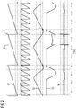
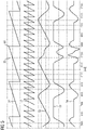
- the representation in FIG 2 shows a course of individual characteristic curves for this example.
- the top curve 50 shows a position profile of the master and a regularly repeating master cycle.
- Such a master cycle relates, for example, to a certain number of bottles 12 that are moved in each master cycle, for example to the filling device 16, and to a movement of the bottles 12 during filling by the filling device 16.
- a second Curve 51 is shown, which illustrates that the master cycle can be divided into individual sections.
- the second curve 51 thus shows the position curve of the master divided into the distance between the bottles. In this way, for example, the movement and the position of individual bottles 12 can be detected.
- the third curve 52 seen from above shows an example of a movement of a slave in relation to the master cycle, and the movement illustrated here is the movement of the in FIG 1 called camera 22, so the position of the third axis.
- the first third (from left to right) of the representation of this curve in FIG 2 a situation is shown in which the slave initially moves at a constant speed in the master cycle in order to achieve a suitable relative position to a bottle 12 moving on the conveyor belt 14 at a specific point in time, so that a camera image can be taken of it . Thereafter, the slave (camera 22) is moved to its home position and the same slave (camera 22) movement occurs in the next master cycle.
- a situation is shown as it occurs when during continuous master cycles, a displacement or offset between the master (conveyor belt 14) and the slave (camera 22) is changed, for example for quality control, not every sixth bottle 12 in a group of bottles 12 moved during the master cycle, but every seventh in the same group Examine Bottle 12. Then, during a master cycle, the movement of the slave has to be scaled in order to reach the position of the bottle 12 that is now relevant in the bottle group and to carry out a synchronous movement with the movement of the conveyor belt 14 while recording the camera image.
- the above-mentioned middle third of the representation is therefore the scaled area (scaling area), which for emphasis in the representation is marked on the one hand by a vertical line labeled 55, which represents the beginning of the scaling area, and another vertical line, labeled 56, which represents the represents the end of the scaling range is limited.
- the representation in 3 shows a scaling function 40 for a linear scaling.
- This scaling function 40 can be used to explain why linear scaling leads to the FIG 2 described discontinuities in the speed and acceleration of a scaled movement of an axis.
- the discontinuity of the scaling function 40 associated with the linear scaling leads to a sudden change in the first derivative of the scaled master value (here the manipulated master value of the cam disc) at the transition points, also referred to below as discontinuities, from the unscaled area to the scaled area and from the scaled area to the unscaled area ), the speed, and corresponding to an abrupt change in the second derivative of the following value, the acceleration.
- a C 2 -continuous function is a function whose first and second derivatives are continuous. Due to the C 2 continuity, a resulting, scaled section can be coupled to the sections preceding and following the scaled area of the movement resulting after scaling with such a scaling function 42 with constant acceleration and coupled in the resulting movement with constant acceleration.
- An acceleration-constant coupling and an acceleration-constant coupling means that the acceleration (and also the underlying speed) only changes steadily and not abruptly during the transition from the non-scaled area to the scaled area and later from the non-scaled area to the non-scaled area.
- a scaling function 42 that can be used for such a scaling of a cam disk is shown as an example in FIG 4 shown.
- the representation in FIG 4 based on the representation in 3 , so reference is made to the explanations there, and between the start and end points (S, E) of the scaled range is - unlike the linear scaling in 3 - now shown a scaling with a C 2 -continuous function.
- the scaled course of the resulting trajectory is also continuous and also continuous in the first and second derivation, so that here, too, speed and acceleration only change continuously and not abruptly .
- a 4th degree Bezier spline acts as the basis for the C 2 -continuous scaling function 42 .
- Such splines and their definition or mathematical basis, in particular the determination of the respective coefficients, are known per se, so that corresponding explanations can be dispensed with here.
- the weight points necessary for specifying the desired gradients and curvatures are determined. These are selected in such a way that a monotonic course of the spline with a homogeneous distribution of curvature results.
- An algorithm for determination of the coefficients and the weighting points of such a C 2 -continuous function is implemented in software in the exemplary embodiment shown and, for example, is part of the control program 32 loaded into the memory 28 of the motion control system 26.
- the representation in 6 shows in a schematically simplified manner that the C 2 -continuous scaling with a C 2 -continuous scaling function 42 can be applied both to the domain of definition and to the range of values of a function 44 to be scaled in each case.
- the function 44 to be scaled is shown symbolically in the middle of the block diagram. This is, for example, a cam disc.
- An underlying polynomial table is stored, for example, as a control algorithm 34 and as a parameterization of the control algorithm 34 in the memory 28 of the motion control system 26 .
- a scaling function block 46 is shown on an input side of the cam disc 44 to be scaled.
- the scaling function block 46 is a functionality implemented here in software for determining a C 2 -continuous scaling function 42 for section-by-section non-linear scaling of the area selected for scaling (see e.g FIG 4 and there the area between the starting point S and the end point E) and thus also a component of the control program 32 loaded into the memory 28 of the motion control system 26.
- the scaling function block 46 implements the above-described sectional scaling of the master value by means of a monotonic C 2 -continuous scaling function 42, so that the area to be scaled is stretched or compressed.
- the C 2 -continuous scaling can additionally or alternatively also relate to the subsequent area of a curve 44 to be scaled in each case.
- a scaling function block 48 downstream of the curve 44 to be scaled is also shown.
- the input-side C 2 -continuous Scaling of cam disk 44 (scaling function block 46) causes the movement information of the master value to be scaled (abscissa of cam disk 44 is scaled).
- the C 2 -continuous scaling of the cam disk 44 on the output side causes the movement information of the following value to be scaled (ordinate of the cam disk 44 is scaled).
- the representation in 6 thus shows that the conductance can be calculated via a C 2 -continuous scaling function 42, as in FIG 4 shown, ie for example a first C 2 -continuous scaling function 42 implemented with the input-side scaling function block 46, can be manipulated.
- This manipulated master value is supplied to cam disk 44 .
- the resulting course of movement (slave unscaled) can be manipulated via a second C 2 -continuous scaling function 42 implemented with the scaling function block 48 on the output side.
- the subsequent value resulting therefrom can then be fed to the third drive 24, for example.
Landscapes
- Engineering & Computer Science (AREA)
- Human Computer Interaction (AREA)
- Manufacturing & Machinery (AREA)
- Physics & Mathematics (AREA)
- General Physics & Mathematics (AREA)
- Automation & Control Theory (AREA)
- Computing Systems (AREA)
- Theoretical Computer Science (AREA)
- Numerical Control (AREA)
- Transmission Devices (AREA)
Description
- Die Erfindung betrifft ein Verfahren zum Betrieb eines Bewegungssteuerungssystems. Sie bezieht sich weiter auf eine Vorrichtung zur Durchführung des Verfahrens, also auf ein nach dem Verfahren arbeitendes Bewegungssteuerungssystem, sowie auf ein Computerprogramm zur Implementierung des Verfahrens und ein Computerprogrammprodukt, also einen Datenträger und dergleichen, auf dem ein solches Computerprogramm gespeichert ist.
- Als Bewegungssteuerungssystem - in der Fachterminologie üblicherweise als Motion Control System bezeichnet - soll hier und im Folgenden eine Vorrichtung zur koordinierten Steuerung und/oder Überwachung von Achsen, zum Beispiel Achsen einer Produktions- oder Bearbeitungsmaschine (Maschine), verstanden werden. Werden mehrere Achsen gekoppelt, spricht man auch von einem elektronischen Gleichlaufverbund oder kurz von einem Gleichlaufverbund. Als Maschine kommt jegliche Motion Control Anwendung, mit der ein Transport, eine Prüfung, sowie eine Be- oder Verarbeitung von Werkstoffen erfolgt, in Betracht.
- Bei dieser Art von Maschinen wird ein Sollwert der Achsen häufig über einen Gleichlaufverbund oder über andere Leitwerte (Position oder Zeit) gebildet.
-
EP 1 220 069 A1 beschreibt ein Verfahren zur Erstellung flexibler Kurvenscheibenfunktionen. Dazu wird eine Bewegung eines Maschinenelementes durch die Kurvenscheibenfunktion abschnittsweise beschrieben, indem einzelne aufeinanderfolgende Bewegungsabschnitte durch Segmente und/oder Punkte definiert werden und zwischen solchen Bewegungsabschnitten nach einer vorgebbaren Interpolationsvorschrift interpoliert wird, wobei Befehle zur Vorgabe und/oder zum Einfügen von Punkten, Segmenten und Interpolationsvorschriften zur Laufzeit bereitgestellt werden, wobei die Kurvenscheibenfunktion über Befehle im Laufzeitsystem einer Maschinensteuerung erstellt wird. -
EP 2 144 127 A1 beschreibt ein Verfahren zum Aufsynchronisieren eines Aufnehmers eines mehrachsigen Handlingsgerätes mit einem aufzunehmenden Objekt, welches von einer Fördereinrichtung mitgeführt wird, und/oder zum Aufsynchronisieren des Aufnehmers mit einer angetriebenen Fördereinrichtung, um ein bereits aufgenommenes Objekt dort abzusetzen. Der Aufnehmer wird entlang einer rechnerisch ermittelten Polynombahn mindestens der 3. Ordnung zwischen einem Startpunkt und einem Zielpunkt aufsynchronisiert. - Bewegungssteuerungssysteme der oben genannten Art bieten dafür spezielle Funktionen, zum Beispiel sogenannte elektronische Kurvengetriebe (VDI2143) an, bei denen der häufig nicht lineare Zusammenhang zwischen Leit- und Folgewert über sogenannte Kurvenscheiben definiert ist. Dabei besteht auch die Möglichkeit, solche elektronischen Kurvenscheiben und dergleichen über ihren Folgewertbereich (Ordinate) und Leitwertbereich (Abszisse) zu skalieren. Hierbei handelt es sich jedoch um eine lineare Skalierung. Eine lineare abschnittsweise Skalierung kann bei geforderter C2-Stetigkeit aufgrund der resultierenden Unstetigkeiten in den Ableitungen jedoch nur in sogenannten Rastbereichen (VDI2143), wenn sich der Folgewert der Kurvenscheibe nicht ändert und somit die Folgeachse steht, verwendet werden.
- Der Erfindung liegt daher die Aufgabe zugrunde, eine verbesserte Möglichkeit zur Skalierung der jeweiligen Folge- und Leitwertebereiche anzugeben. Einsatzfälle sind die Vorgabe eines Versatzwinkels bei Getriebe- und Kurvengleichläufen, eine Druckmarkenkorrektur oder eine Anpassung synchroner Bewegungen mehrerer Achsen.
- Diese Aufgabe wird erfindungsgemäß mit den Merkmalen des Anspruchs 1 gelöst.
- Die oben genannte Aufgabe wird ebenfalls durch eine Vorrichtung zur Durchführung des Verfahrens, nämlich ein nach dem Verfahren arbeitendes Bewegungssteuerungssystem, gelöst. Dazu ist vorgesehen, dass die Vorrichtung bzw. das Bewegungssteuerungssystem Mittel zur Durchführung des Verfahrens umfasst.
- Als ein derartiges Mittel kommt insbesondere ein Computerprogramm zur Durchführung des Verfahrens und der davon umfassten Verfahrensschritte in Betracht. Die Erfindung ist damit einerseits auch ein Computerprogramm mit durch einen Computer, nämlich das Bewegungssteuerungssystem und eine davon umfasste Verarbeitungseinheit, ausführbaren Programmcodeanweisungen und andererseits ein Speichermedium mit einem derartigen Computerprogramm, also ein Computerprogrammprodukt mit Programmcodemitteln, sowie schließlich ein Bewegungssteuerungssystem mit einem Speicher, in den als Mittel zur Durchführung des Verfahrens und seiner Ausgestaltungen ein solches Computerprogramm geladen oder ladbar ist.
- Die Erfindung geht dabei von der Erkenntnis aus, dass sich eine C2-stetige Skalierungsfunktion realisieren lässt, indem der Skalierungsbereich über sogenannte Beziersplines, und zwar Beziersplines 4. Ordnung, definiert wird. Über Gewichtspunkte (Gewichte), werden die Steigungen und Krümmungen der Beziersplines vorgegeben. Die Gewichtspunkte werden nach den bekannten Spline Algorithmen (zum Beispiel: Numerik-Algorithmen, Springer Verlag ISBN 3-540-62669-7) ermittelt. Durch die geeignete Wahl der Gewichtspunkte wird ein monotoner Verlauf der Beziersplines mit einer homogenen Krümmungsverteilung erreicht.
- Das Verfahren zeichnet sich entsprechend dadurch aus, dass die Gewichtspunkte eines die C2-stetige Funktion einschließenden und deren Verlauf bestimmenden Polygons ermittelt werden, welche einen monotonen Verlauf der C2-stetigen Skalierungsfunktion und eine homogene Krümmungsverteilung entlang der C2-stetigen Skalierungsfunktion gewährleisten.
- Der Vorteil der Erfindung besteht darin, dass der Verlauf der Kurvenscheibe des Gleichlaufverbunds aufgrund der C2-Stetigkeit der Skalierungsfunktion unabhängig von der Übertragungsfunktion des Gleichlaufverbundes im kompletten Leit- und Folgebereich abschnittsweise C2-stetig gestreckt oder gestaucht werden können.
- Einsatzgebiete für die hier vorgestellte Möglichkeit zum abschnittsweisen Strecken oder Stauchen von in einem Gleichlaufverbund koordinierten Achsen (partielle nichtlineare Skalierung) sind die Vorgabe eines Versatzwinkels, eine Druckmarkenkorrektur und eine synchrone Bewegung mehrerer Achsen.
- Ein konkretes Beispiel betrifft die Qualitätssicherung bei kontinuierlich laufenden Maschinen und dort die Vorgabe eines Versatzwinkels zwischen einer ersten Achse (Master) und einer zweiten Achse (Slave). Dabei wird über eine Mechanik jedes n-te Produkt eines kontinuierlich laufenden Prozesses geprüft. Nach einer vorgebbaren Anzahl an Produkten soll die Stelle der Qualitätssicherung gewechselt werden. Dies wäre beispielsweise über die Vorgabe eines überlagerten Offsets möglich. Wird dieser Offset durch eine überlagerte Positionierung abgesetzt, führt dies jedoch zu dem Nachteil, dass zum Zeitpunkt der Ausgleichbewegung keine feste Kopplung zwischen Master und Slave vorliegt. Wird zu diesem Zeitpunkt der Master gestoppt (z.B. durch Notaus), könnte dies dazu führen, dass der Slave rückwärts läuft. Dies ist bei vielen Maschinen jedoch nicht zulässig. Dieses Beispiel wird im speziellen Beschreibungsteil mit weiteren Details erläutert.
- Nachfolgend wird ein Ausführungsbeispiel der Erfindung anhand der Zeichnung näher erläutert. Einander entsprechende Gegenstände oder Elemente sind in allen Figuren mit den gleichen Bezugszeichen versehen.
- Es zeigen
- FIG 1
- eine Produktionsmaschine, die für eine Steuerung gemäß einem Verfahren wie hier beschrieben in Betracht kommt und dafür ein entsprechendes Antriebs- oder Bewegungssteuerungssystem aufweist,
- FIG 2
- einen Verlauf aufgenommener Kurven zu dem Ausführungsbeispiel gemäß
FIG 1 , - FIG 3
- eine lineare Skalierungsfunktion,
- FIG 4
- eine Skalierungsfunktion der hier vorgeschlagenen Art, nämlich eine C2-stetige Skalierungsfunktion,
- FIG 5
- einen Verlauf aufgenommener Kurven - ähnlich wie in
FIG 2 - bei Anwendung einer C2-stetigen Skalierungsfunktion und - FIG 6
- ein Blockdiagramm mit möglichen Orten zur Anwendung einer Funktionalität zur Realisierung der hier vorgeschlagenen Skalierung.
-
FIG 1 zeigt in schematisch vereinfachter Form als Beispiel für eine Bearbeitungs- oder Werkzeugmaschine 10 eine Produktionsmaschine 10 zum Befüllen von Flaschen 12. Der hier vorgeschlagene Ansatz kommt selbstverständlich für Produktionsmaschinen 10 unterschiedlichster Art in Betracht und ist in keinster Weise auf das im Folgenden erläuterte Ausführungsbeispiel beschränkt. - Die in
FIG 1 gezeigte Produktionsmaschine 10 umfasst ein Förderband 14, auf dem sich die zu befüllenden Flaschen 12 befinden. Mit dem Förderband 14 werden die Flaschen 12 zu einer Fülleinrichtung 16 transportiert, die sich beim Befüllen der Flaschen 12 teilweise synchron mit dem Förderband 14 bewegt. Dafür umfasst die Produktionsmaschine 10 Antriebe, nämlich zumindest einen ersten Antrieb 18 für das Förderband 14 und einen zweiten Antrieb 20 zur Bewegung der Fülleinrichtung 16. Zur Qualitätskontrolle ist eine Kamera 22 oder dergleichen vorgesehen. Die Kamera 22 wird mit einem eigenen Antrieb, hier einem dritten Antrieb 24, zumindest zeitweise synchron mit den Flaschen 12 auf dem Förderband 14 bewegt, um ein Bild von jeweils einer Flasche 12 zu erfassen. Im Rahmen der Qualitätskontrolle soll nicht jede einzelne Flasche 12 untersucht werden, sondern es reicht aus, wenn von jeder n-ten Flasche mittels der Kamera 22 ein Bild erfasst wird, das in an sich bekannter Art und Weise zur Qualitätskontrolle ausgewertet wird. - Die Position des Förderbands 14 bestimmt die Position der Fülleinrichtung 16 und die Position der Kamera 22. Das Förderband 14 wird demgemäß entsprechend der üblichen Terminologie als Master bezeichnet. Entsprechend handelt es sich bei der Fülleinrichtung 16 und der Kamera 22 um Slaves, denn deren Bewegung oder Position ist von der Bewegung/Position des Masters (Förderband 14) abhängig. Die Bezeichnung Master und Slave wird im Folgenden auch für die jeweiligen Antriebe 18, 20, 24 verwendet. Der Master und der oder jeder Slave einer Produktionsmaschine 10 stellen einen üblicherweise auch als Achse bezeichneten Freiheitsgrad der Produktionsmaschine 10 dar.
- Zur Steuerung und Überwachung der Produktionsmaschine 10 ist in an sich bekannter Art und Weise ein Bewegungssteuerungssystem 26 vorgesehen. Dieses umfasst einen Speicher 28 und zumindest eine Verarbeitungseinheit 30 in Form von oder nach Art eines Mikroprozessors. In den Speicher 28 ist ein als Steuerungsprogramm 32 fungierendes Computerprogramm geladen, das im Betrieb des Bewegungssteuerungssystems 26 durch die jeweilige Verarbeitungseinheit 30 ausgeführt wird. Das Steuerungsprogramm 32 umfasst dafür eine Softwareimplementation eines oder mehrerer Steuerungsalgorithmen 34 zur Ansteuerung der Antriebe 18, 20, 24. Unter Kontrolle des Steuerungsprogramms 32 werden dabei über eine Antriebsregelungseinheit 36 Ausgangssignale 38 zur Ansteuerung des jeweiligen Antriebs 18, 20, 24 ausgegeben.
- Die Darstellung in
FIG 2 zeigt zu diesem Beispiel einen Verlauf einzelner charakteristischer Kurven. Die oberste Kurve 50 zeigt einen Positionsverlauf des Masters und einen sich regelmäßig wiederholenden Masterzyklus. Ein solcher Masterzyklus bezieht sich zum Beispiel auf eine bestimmte Anzahl von Flaschen 12, die in jeweils einem Masterzyklus bewegt werden, zum Beispiel zur Fülleinrichtung 16, und auf eine Bewegung der Flaschen 12 während des Befüllens durch die Fülleinrichtung 16. Unterhalb des Masterzyklus ist eine zweite Kurve 51 gezeigt, die veranschaulicht, dass der Masterzyklus in einzelne Abschnitte aufgeteilt werden kann. Die zweite Kurve 51 zeigt also den auf den Flaschenabstand unterteilten Positionsverlauf des Masters. Auf diese Weise werden zum Beispiel die Bewegung und die Position einzelner Flaschen 12 erfassbar. - Darunter ist mit der von oben gesehen dritten Kurve 52 exemplarisch eine Bewegung eines Slaves in Relation zum Masterzyklus dargestellt und bei der hier veranschaulichten Bewegung handelt es sich um die Bewegung der in
FIG 1 genannten Kamera 22, also um den Positionsverlauf der dritten Achse. Im (von links nach rechts gesehen) ersten Drittel der Darstellung dieser Kurve inFIG 2 ist eine Situation gezeigt, bei der sich der Slave im Masterzyklus zunächst mit konstanter Geschwindigkeit bewegt, um auf diese Weise zu einem bestimmten Zeitpunkt eine geeignete Relativposition zu einer auf dem Förderband 14 bewegten Flasche 12 zu erreichen, so dass von dieser ein Kamerabild aufgenommen werden kann. Danach wird der Slave (die Kamera 22) in seine Ausgangsposition bewegt und im nächsten Masterzyklus erfolgt dieselbe Bewegung des Slaves (der Kamera 22). - Im mittleren Drittel der Darstellung, ist eine Situation gezeigt, wie sie eintritt, wenn während kontinuierlich durchlaufender Masterzyklen ein Versatz oder Offset zwischen dem Master (Förderband 14) und dem Slave (Kamera 22) geändert wird, um zum Beispiel zur Qualitätskontrolle nicht jede sechste Flasche 12 in einer während des Masterzyklus bewegten Gruppe von Flaschen 12, sondern in derselben Gruppe jede siebte Flasche 12 zu untersuchen. Dann muss während eines Masterzyklus die Bewegung des Slaves skaliert werden, um die Position der jetzt in der Flaschengruppe relevanten Flasche 12 zu erreichen und während der Aufnahme des Kamerabildes eine synchrone Bewegung mit der Bewegung des Förderbands 14 durchzuführen. Im oben genannten mittleren Drittel der Darstellung befindet sich also der skalierte Bereich (Skalierungsbereich), der zur Hervorhebung in der Darstellung einerseits durch eine mit 55 bezeichnete vertikale Linie, die den Anfang des Skalierungsbereichs darstellt, und eine mit 56 bezeichnete weitere vertikale Linie, die das Ende des Skalierungsbereichs darstellt, begrenzt ist.
- Man erkennt aber bei den beiden unterhalb der Bewegungsbahn des Slaves (Positionsverlauf der dritten Achse 52) dargestellten Kurven 53, 54, nämlich eine Kurve 53 für den Geschwindigkeitsverlauf der dritten Achse und eine Kurve 54 für den Beschleunigungsverlauf der dritten Achse, dass eine lineare Skalierung zu Unstetigkeiten im Geschwindigkeitsverlauf führt und dass es zu impulsartigen Spitzen im Beschleunigungsverlauf kommt. Dies belastet zumindest den betroffenen Antrieb 24 und auch die Produktionsmaschine 10 insgesamt.
- Die Darstellung in
FIG 3 zeigt eine Skalierungsfunktion 40 für eine lineare Skalierung. Anhand dieser Skalierungsfunktion 40 lässt sich erläutern, warum es bei einer linearen Skalierung zu den exemplarisch anhand vonFIG 2 beschriebenen Unstetigkeiten in der Geschwindigkeit und der Beschleunigung einer skalierten Bewegung einer Achse kommt. - In
FIG 3 ist auf der Abszisse der Leitbereich der Masterachse (bei der inFIG 1 gezeigten Situation das Förderband 14) aufgetragen. Entsprechend ist auf der Ordinate der skalierte Leitwert aufgetragen. Dieser wird als Leitwert für die Kurvenscheibe verwendet. Die Skalierung findet zwischen einem mit "S" bezeichneten Startpunkt und einem mit "E" bezeichneten Endpunkt statt und in der Darstellung ist unmittelbar erkennbar, dass sich aufgrund der linearen Skalierung an den beiden jeweils mit einem Ausrufezeichen (!) gekennzeichneten Stellen eine Unstetigkeit in der Ableitung der Skalierungsfunktion 40 ergibt, die zu Unstetigkeiten im Geschwindigkeits- und Beschleunigungsverlauf der resultierenden Bewegungsbahn (sieheFIG 2 ) führt. - Für die Bereiche vor und nach dem skalierten Bereich, also zwischen dem Startpunkt "S" und dem Endpunkt "E", ist mit Δ=1 und Δ2=0 die Steigung Δ der Skalierungsfunktion 40 und die Krümmung Δ2 der Skalierungsfunktion 40 angegeben. Eine Steigung Δ=1 bedeutet, dass der Leitwert in diesem Bereich nicht skaliert wird. Eine Krümmung Δ2=0 bedeutet, dass in dem entsprechenden Abschnitt der Skalierungsfunktion 40 beim Bewegen des Masters und des Slaves entlang der jeweiligen Bewegungsbahn aufgrund der zugrunde liegenden Skalierungsfunktion keine Änderung der aus der Kurvenscheibe resultierenden Geschwindigkeit und Beschleunigung erfolgt.
- Die mit der linearen Skalierung verbundene Unstetigkeit der Skalierungsfunktion 40 führt an den im Folgenden auch als Unstetigkeitsstellen bezeichneten Übergangsstellen vom unskalierten Bereich zum skalierten Bereich und vom skalierten Bereich zum unskalierten Bereich zu einer sprunghaften Änderung der ersten Ableitung des skalierten Leitwerts (hier der manipulierte Leitwert der Kurvenscheibe), der Geschwindigkeit, und entsprechend zu einer stoßartigen Änderung der zweiten Ableitung des Folgewerts, der Beschleunigung.
- Solche sprunghaften Änderungen der Geschwindigkeit sind für die beteiligten Aggregate, also die jeweiligen Antriebe 24 und die nachfolgende Mechanik, ungünstig, so dass eine lineare abschnittsweise Skalierung aufgrund der resultierenden Unstetigkeiten bisher nur in sogenannten Rastbereichen möglich war. Dementsprechend war also zum Beispiel eine Skalierung des Wertebereichs des Masters dort möglich, wo der Slave keine Bewegung ausführt, also in Stillstand ist. Dies wird als Rastposition bezeichnet.
- Um solche Unstetigkeitsstellen und damit einhergehende sprunghafte Geschwindigkeitsänderungen sowie stoßartige Beschleunigungsänderungen zu vermeiden, ist gemäß dem hier vorgestellten Ansatz vorgesehen, dass der zu skalierende Bereich mittels einer monotonen und C2-stetigen Funktion gestreckt oder gestaucht wird. Eine C2-stetige Funktion ist dabei eine Funktion, deren erste und zweite Ableitung stetig ist. Aufgrund der C2-Stetigkeit ist ein resultierender, skalierter Abschnitt an die dem skalierten Bereich vorangehenden und nachfolgenden Abschnitte der nach der Skalierung mit einer solchen Skalierungsfunktion 42 resultierenden Bewegung beschleunigungsstetig ankoppelbar und in der resultierenden Bewegung beschleunigungsstetig angekoppelt. Eine beschleunigungsstetige Ankoppelbarkeit und eine beschleunigungsstetige Ankoppelung bedeutet, dass sich die Beschleunigung (und auch die zugrunde liegende Geschwindigkeit) beim Übergang vom nicht skalierten Bereich zum skalierten Bereich und später vom skalierten Bereich zum nicht skalierten Bereich nur stetig und nicht sprunghaft ändert.
- Eine für eine solche Skalierung einer Kurvenscheibe verwendbare Skalierungsfunktion 42 ist exemplarisch in
FIG 4 gezeigt. Die Darstellung inFIG 4 basiert auf der Darstellung inFIG 3 , so dass auf die dortigen Ausführungen verwiesen wird, und zwischen den Start- und Endpunkten (S, E) des skalierten Bereichs ist - anders als die lineare Skalierung inFIG 3 - jetzt eine Skalierung mit einer C2-stetigen Funktion gezeigt. Aufgrund einer solchen Skalierung mit einer C2-stetigen Funktion ergibt sich im Startpunkt (S) und im Endpunkt (E) des skalierten Bereichs die oben erwähnte beschleunigungsstetige Ankoppelung einer Bewegungsbahn an die nicht skalierten Abschnitte der Bewegungsbahn und zwischen dem Start- und Endpunkt (S, E) ist der skalierte Verlauf der resultierenden Bewegungsbahn ebenso wie die zugrunde liegende Skalierungsfunktion 42 ebenfalls stetig und auch in der ersten und zweiten Ableitung stetig, so dass sich auch hier Geschwindigkeit und Beschleunigung nur stetig und nicht sprunghaft ändern. - Das Resultat einer solchen Skalierung mit einer C2-stetigen Skalierungsfunktion 42 (
FIG 4 ) ist in der Darstellung inFIG 5 gezeigt, wobei speziell die Darstellung des Beschleunigungsverlaufs 54 der dritten Achse als qualitative Darstellung mit einer im Vergleich zu der Darstellung inFIG 2 unterschiedlichen Skalierung der Ordinate zu sehen ist. Hier erfolgt im zweiten vollständig gezeigten Masterzyklus, also zwischen den Anfang und das Ende des Skalierungsbereichs darstellenden vertikalen Linien 55, 56, eine Skalierung der Bewegung der dritten Achse, also der Slaveachse. Die Skalierung basiert diesmal - im Unterschied zu der inFIG 2 gezeigten Skalierung - nicht auf einer linearen Skalierungsfunktion 40 (FIG 3 ), sondern auf einer C2-stetigen Skalierungsfunktion 42, wie diese inFIG 4 gezeigt ist. Man erkennt im Vergleich zur Darstellung inFIG 2 den Unterschied im resultierenden Geschwindigkeits- und Beschleunigungsverlauf 53, 54. Demnach vermeidet die Skalierung mit einer C2-stetigen Skalierungsfunktion 42 Unstetigkeiten im Geschwindigkeitsverlauf 53 der dritten Achse und im Beschleunigungsverlauf 54 der dritten Achse. - Als Basis für die C2-stetige Skalierungsfunktion 42 fungiert dabei ein Bezierspline 4. Grades. Solche Splines und deren Definition bzw. mathematische Grundlage, insbesondere die Bestimmung der jeweiligen Koeffizienten, sind an sich bekannt, so dass hier auf entsprechende Erläuterungen verzichtet werden kann. Unter Verwendung des ebenfalls an sich bekannten Sline Algorithmus werden die zur Vorgabe gewünschter Steigungen und Krümmungen notwendigen Gewichtspunkte ermittelt. Diese werden so gewählt, dass sich ein monotoner Verlauf des Splines mit einer homogenen Krümmungsverteilung ergibt. Ein Algorithmus zur Bestimmung der Koeffizienten und der Gewichtspunkte einer solchen C2-stetigen Funktion ist beim gezeigten Ausführungsbeispiel in Software implementiert und zum Beispiel Bestandteil des in den Speicher 28 des Bewegungssteuerungssystems 26 geladenen Steuerungsprogramms 32.
- Die Darstellung in
FIG 6 zeigt in schematisch vereinfachter Art und Weise, dass die C2-stetige Skalierung mit einer C2-stetigen Skalierungsfunktion 42 sowohl auf den Definitionsbereich wie auch auf den Wertebereich einer jeweils zu skalierenden Funktion 44 angewandt werden kann. Die zu skalierende Funktion 44 ist in dem Blockschaltbild symbolisch in der Mitte gezeigt. Dabei handelt es sich zum Beispiel um eine Kurvenscheibe. Eine zugrunde liegende Polynomtabelle ist zum Beispiel als Steuerungsalgorithmus 34 sowie als Parametrierung des Steuerungsalgorithmus 34 im Speicher 28 des Bewegungssteuerungssystems 26 hinterlegt. - In Bezug auf eine solche Kurvenscheibe kann deren Leitwert C2-stetig skaliert werden. Dafür ist auf einer Eingangsseite der zu skalierenden Kurvenscheibe 44 ein Skalierungsfunktionsblock 46 gezeigt. Der Skalierungsfunktionsblock 46 ist eine hier in Software implementierte Funktionalität zur Ermittlung einer C2-stetigen Skalierungsfunktion 42 zur abschnittsweisen nichtlinearen Skalierung des jeweils zur Skalierung ausgewählten Bereichs (siehe z.B.
FIG 4 und dort den Bereich zwischen dem Startpunkt S und dem Endpunkt E) und damit ebenfalls Bestandteil des in den Speicher 28 des Bewegungssteuerungssystems 26 geladenen Steuerungsprogramms 32. Der Skalierungsfunktionsblock 46 realisiert die oben beschriebene abschnittsweise Skalierung des Leitwerts mittels einer monotonen C2-stetigen Skalierungsfunktion 42, so dass der zu skalierende Bereich gestreckt oder gestaucht wird. Die C2-stetige Skalierung kann sich zusätzlich oder alternativ auch auf den Folgebereich einer jeweils zu skalierenden Kurve 44 beziehen. Insofern ist inFIG 6 auch ein der zu skalierenden Kurve 44 nachgeordneter Skalierungsfunktionsblock 48 gezeigt. Die eingangsseitige C2-stetige Skalierung der Kurvenscheibe 44 (Skalierungsfunktionsblock 46) bewirkt eine Skalierung der Bewegungsinformationen des Leitwerts (Abszisse der Kurvenscheibe 44 wird skaliert). Die ausgangsseitige C2-stetige Skalierung der Kurvenscheibe 44 (Skalierungsfunktionsblock 48) bewirkt eine Skalierung der Bewegungsinformationen des Folgewerts (Ordinate der Kurvenscheibe 44 wird skaliert). - Die Darstellung in
FIG 6 zeigt damit, dass der Leitwert über eine C2-stetige Skalierungsfunktion 42, wie inFIG 4 gezeigt, also zum Beispiel eine mit dem eingangsseitigen Skalierungsfunktionsblock 46 realisierte erste C2-stetige Skalierungsfunktion 42, manipuliert werden kann. Dieser manipulierte Leitwert wird der Kurvenscheibe 44 zugeführt. Der daraus resultierende Bewegungsverlauf (Slave unskaliert) kann über eine mit dem ausgangsseitigen Skalierungsfunktionsblock 48 realisierte zweite C2-stetige Skalierungsfunktion 42 manipuliert werden. Der sich daraus ergebende Folgewert kann dann beispielsweise dem dritten Antrieb 24 zugeführt werden.
Claims (4)
- Verfahren zum Betrieb eines Bewegungssteuerungssystems (26), wobei zum abschnittsweisen Skalieren einer Bewegungsbahn eine C2-stetige Skalierungsfunktion (42) verwendet wird, wobei nach einem Spline-Algorithmus Eckpunkte eines die C2-stetige Skalierungsfunktion (42) einschließenden und deren Verlauf bestimmenden Polygons ermittelt werden, die einen monotonen Verlauf der C2-stetigen Skalierungsfunktion (42) und eine homogene Krümmungsverteilung entlang der C2-stetigen Skalierungsfunktion (42) gewährleisten.
- Computerprogramm (32) mit Programmcodemitteln, um alle Schritte des Anspruchs 1 durchzuführen, wenn das Computerprogramm (32) auf einem Steuergerät eines Bewegungssteuerungssystems (26) ausgeführt wird.
- Computerprogrammprodukt, insbesondere digitales Speichermedium, mit Programmcodemitteln, die auf einem computerlesbaren Datenträger gespeichert sind, um das Verfahren nach Anspruch 1 durchzuführen, wenn das Computerprogrammprodukt auf einem Steuergerät eines Bewegungssteuerungssystems (26) ausgeführt wird.
- Bewegungssteuerungssystem (26) mit einer Verarbeitungseinheit (30) und einem Speicher (28), in den ein Computerprogramm (32) nach Anspruch 2 geladen ist, das im Betrieb des Bewegungssteuerungssystems (26) durch die Verarbeitungseinheit (30) ausgeführt wird.
Priority Applications (3)
| Application Number | Priority Date | Filing Date | Title |
|---|---|---|---|
| EP13196906.5A EP2884361B1 (de) | 2013-12-12 | 2013-12-12 | Verfahren zum Betrieb eines Bewegungssteuerungssystems und nach dem Verfahren arbeitendes Bewegungssteuerungssystem sowie Computerprogramm zur Implementierung des Verfahrens |
| US14/567,673 US10359759B2 (en) | 2013-12-12 | 2014-12-11 | Method for operating a motion control system and motion control system operating according to the method as well as computer program for implementing the method |
| CN201410764748.9A CN104714471A (zh) | 2013-12-12 | 2014-12-11 | 运行运动控制系统的方法和运动控制系统和方法执行程序 |
Applications Claiming Priority (1)
| Application Number | Priority Date | Filing Date | Title |
|---|---|---|---|
| EP13196906.5A EP2884361B1 (de) | 2013-12-12 | 2013-12-12 | Verfahren zum Betrieb eines Bewegungssteuerungssystems und nach dem Verfahren arbeitendes Bewegungssteuerungssystem sowie Computerprogramm zur Implementierung des Verfahrens |
Publications (2)
| Publication Number | Publication Date |
|---|---|
| EP2884361A1 EP2884361A1 (de) | 2015-06-17 |
| EP2884361B1 true EP2884361B1 (de) | 2022-08-10 |
Family
ID=49753086
Family Applications (1)
| Application Number | Title | Priority Date | Filing Date |
|---|---|---|---|
| EP13196906.5A Active EP2884361B1 (de) | 2013-12-12 | 2013-12-12 | Verfahren zum Betrieb eines Bewegungssteuerungssystems und nach dem Verfahren arbeitendes Bewegungssteuerungssystem sowie Computerprogramm zur Implementierung des Verfahrens |
Country Status (3)
| Country | Link |
|---|---|
| US (1) | US10359759B2 (de) |
| EP (1) | EP2884361B1 (de) |
| CN (1) | CN104714471A (de) |
Families Citing this family (4)
| Publication number | Priority date | Publication date | Assignee | Title |
|---|---|---|---|---|
| US10268183B2 (en) * | 2015-03-04 | 2019-04-23 | Omron Corporation | Control device and method of synchronizing control |
| EP3244270B1 (de) | 2016-05-12 | 2018-09-19 | Siemens Aktiengesellschaft | Regeleinrichtung mit lernfähiger fehlerkompensation |
| EP3321754B1 (de) | 2016-11-11 | 2020-09-09 | Siemens Aktiengesellschaft | Verfahren zur optimierung von bewegungsprofilen, computerprogrammprodukt, steuereinrichtung und anlage oder roboter |
| US12210335B2 (en) * | 2021-06-03 | 2025-01-28 | Intrinsic Innovation Llc | Workcell modeling using motion profile matching and swept profile matching |
Citations (2)
| Publication number | Priority date | Publication date | Assignee | Title |
|---|---|---|---|---|
| EP1220069A1 (de) * | 2000-12-27 | 2002-07-03 | Siemens Aktiengesellschaft | Verfahren zur Erstellung flexibler Kurvenscheibenfunktionen über das Steuerungs- oder Anwenderprogramm |
| EP2144127A1 (de) * | 2008-07-08 | 2010-01-13 | Siemens Aktiengesellschaft | Verfahren zum Aufsynchronisieren eines Aufnehmers eines Handlingsgerätes, Anwendungen des Verfahrens, Datenspeichermedium, Steuergerät, Handlingsgerät sowie Verbund aus Handlingsgerät und Steuergerät |
Family Cites Families (8)
| Publication number | Priority date | Publication date | Assignee | Title |
|---|---|---|---|---|
| JP2929996B2 (ja) * | 1996-03-29 | 1999-08-03 | トヨタ自動車株式会社 | 工具点列発生方法 |
| US5904745A (en) * | 1997-05-19 | 1999-05-18 | Owens-Brockway Glass Container Inc. | Generation of sweepout motion profile in an individual section glassware forming system |
| US6402089B1 (en) * | 2001-03-02 | 2002-06-11 | General Dynamics Advanced Technology Services, Inc. | System for control of active system for vibration and noise reduction |
| JP4003792B2 (ja) * | 2004-11-17 | 2007-11-07 | オムロン株式会社 | サーボモータ制御システム |
| EP1869531B1 (de) | 2005-03-23 | 2020-04-22 | Hurco Companies Inc. | Verfahren zur toleranzbasierten pfadplanung |
| DE102005027437B4 (de) | 2005-06-14 | 2013-11-21 | Siemens Aktiengesellschaft | Verfahren zur Bewegungsführung eines bewegbaren Maschinenelements einer Lade- und Entladevorrichtung eines Hochregals oder eines Kranes |
| DE102007006422B4 (de) * | 2007-02-05 | 2024-06-06 | Robert Bosch Gmbh | Verfahren zum Betreiben von Maschinen mit anpassbaren Bewegungsprofilen |
| US7962240B2 (en) * | 2007-12-20 | 2011-06-14 | Ge Intelligent Platforms, Inc. | Methods and systems for synchronizing a control signal of a slave follower with a master source |
-
2013
- 2013-12-12 EP EP13196906.5A patent/EP2884361B1/de active Active
-
2014
- 2014-12-11 CN CN201410764748.9A patent/CN104714471A/zh active Pending
- 2014-12-11 US US14/567,673 patent/US10359759B2/en active Active
Patent Citations (2)
| Publication number | Priority date | Publication date | Assignee | Title |
|---|---|---|---|---|
| EP1220069A1 (de) * | 2000-12-27 | 2002-07-03 | Siemens Aktiengesellschaft | Verfahren zur Erstellung flexibler Kurvenscheibenfunktionen über das Steuerungs- oder Anwenderprogramm |
| EP2144127A1 (de) * | 2008-07-08 | 2010-01-13 | Siemens Aktiengesellschaft | Verfahren zum Aufsynchronisieren eines Aufnehmers eines Handlingsgerätes, Anwendungen des Verfahrens, Datenspeichermedium, Steuergerät, Handlingsgerät sowie Verbund aus Handlingsgerät und Steuergerät |
Also Published As
| Publication number | Publication date |
|---|---|
| US10359759B2 (en) | 2019-07-23 |
| US20150168940A1 (en) | 2015-06-18 |
| EP2884361A1 (de) | 2015-06-17 |
| CN104714471A (zh) | 2015-06-17 |
Similar Documents
| Publication | Publication Date | Title |
|---|---|---|
| EP2691824B1 (de) | Verfahren zum bearbeiten von werkstücken mittels einer numerisch gesteuerten werkstückbearbeitungsvorrichtung sowie werkstückbearbeitungsvorrichtung | |
| DE3411651C1 (de) | Regelanordnung fuer den Gleichlauf mehrerer Antriebe | |
| DE102005015810B4 (de) | Bearbeitungszeit-Berechnungsvorrichtung | |
| DE112014005564B4 (de) | Reibungsidentifizierungsverfahren und Reibungsidentifizierungsgerät | |
| DE4121531C2 (de) | Bewegungssteuergerät | |
| DE102011018536B4 (de) | Numerische Steuerung mit einer Oszillationsvorgangsfunktion, die im Stande ist, die Geschwindigkeit in einem optionalen Abschnitt zu ändern | |
| DE102015007132B4 (de) | Motorsteuervorrichtung | |
| EP2181311B1 (de) | Verfahren und vorrichtung zur dynamischen kontrollwägung | |
| DE102009023399B4 (de) | Positionssteuerungsvorrichtung | |
| EP3818420B1 (de) | Zeitoptimierte bewegungsführung zwischen bahnabschnitten | |
| EP3321754A1 (de) | Verfahren zur optimierung von bewegungsprofilen, computerprogrammprodukt, steuereinrichtung und anlage oder roboter | |
| DE102005063193A1 (de) | Vorrichtung und Verfahren zum Gruppieren von Stückgut | |
| EP3438773B1 (de) | Bearbeitung von werkstücken mit modellgestützter fehlerkompensation | |
| EP2438491B1 (de) | Verfahren und vorrichtung zur generierung eines variablen bewegungsprofils für eine antriebseinheit einer maschine | |
| DE102016007688A1 (de) | Numerische Steuervorrichtung, die entsprechend einer Vorschubgeschwindigkeitsänderung eine dreidimensionale Interferenzprüfung durchführt | |
| EP2884361A1 (de) | Verfahren zum Betrieb eines Bewegungssteuerungssystems und nach dem Verfahren arbeitendes Bewegungssteuerungssystem sowie Computerprogramm zur Implementierung des Verfahrens | |
| EP2192465B1 (de) | Regelung eines Folgeantriebs mit dynamischer Ermittlung der Dynamik der Leitachse | |
| DE102015013603B4 (de) | Numerische Steuervorrichtung | |
| DE102016012042A1 (de) | Numerische Steuerung mit Positionierung zur Vermeidung einer Kollision mit einem Werkstück | |
| EP2545418A1 (de) | Verfahren zur bestimmung eines optimierten sollkurvenverlaufs bei einer mehrachsigen maschine zur fliegenden bearbeitung von fördergut | |
| EP2902859A1 (de) | Steuereinrichtung mit integriertem Optimierer | |
| DE69324414T2 (de) | Verfahren zur steuerung eines servomotors | |
| EP3658996B1 (de) | Verfahren zum betrieb einer numerisch gesteuerten produktionsanlage sowie produktionsanlage dazu | |
| DE102011121839A1 (de) | Verfahren zur Bewegungssteuerung mit Trägheitsmoment - Ermittlung | |
| DE102016220577A1 (de) | Verfahren zum Optimieren von Bewegungskonturen eines Manipulators |
Legal Events
| Date | Code | Title | Description |
|---|---|---|---|
| PUAI | Public reference made under article 153(3) epc to a published international application that has entered the european phase |
Free format text: ORIGINAL CODE: 0009012 |
|
| 17P | Request for examination filed |
Effective date: 20131212 |
|
| AK | Designated contracting states |
Kind code of ref document: A1 Designated state(s): AL AT BE BG CH CY CZ DE DK EE ES FI FR GB GR HR HU IE IS IT LI LT LU LV MC MK MT NL NO PL PT RO RS SE SI SK SM TR |
|
| AX | Request for extension of the european patent |
Extension state: BA ME |
|
| R17P | Request for examination filed (corrected) |
Effective date: 20151217 |
|
| RBV | Designated contracting states (corrected) |
Designated state(s): AL AT BE BG CH CY CZ DE DK EE ES FI FR GB GR HR HU IE IS IT LI LT LU LV MC MK MT NL NO PL PT RO RS SE SI SK SM TR |
|
| RAP1 | Party data changed (applicant data changed or rights of an application transferred) |
Owner name: SIEMENS AKTIENGESELLSCHAFT |
|
| STAA | Information on the status of an ep patent application or granted ep patent |
Free format text: STATUS: EXAMINATION IS IN PROGRESS |
|
| 17Q | First examination report despatched |
Effective date: 20190524 |
|
| GRAP | Despatch of communication of intention to grant a patent |
Free format text: ORIGINAL CODE: EPIDOSNIGR1 |
|
| STAA | Information on the status of an ep patent application or granted ep patent |
Free format text: STATUS: GRANT OF PATENT IS INTENDED |
|
| INTG | Intention to grant announced |
Effective date: 20220322 |
|
| GRAS | Grant fee paid |
Free format text: ORIGINAL CODE: EPIDOSNIGR3 |
|
| GRAA | (expected) grant |
Free format text: ORIGINAL CODE: 0009210 |
|
| STAA | Information on the status of an ep patent application or granted ep patent |
Free format text: STATUS: THE PATENT HAS BEEN GRANTED |
|
| AK | Designated contracting states |
Kind code of ref document: B1 Designated state(s): AL AT BE BG CH CY CZ DE DK EE ES FI FR GB GR HR HU IE IS IT LI LT LU LV MC MK MT NL NO PL PT RO RS SE SI SK SM TR |
|
| REG | Reference to a national code |
Ref country code: GB Ref legal event code: FG4D Free format text: NOT ENGLISH |
|
| REG | Reference to a national code |
Ref country code: AT Ref legal event code: REF Ref document number: 1511022 Country of ref document: AT Kind code of ref document: T Effective date: 20220815 Ref country code: CH Ref legal event code: EP |
|
| REG | Reference to a national code |
Ref country code: DE Ref legal event code: R096 Ref document number: 502013016209 Country of ref document: DE |
|
| REG | Reference to a national code |
Ref country code: IE Ref legal event code: FG4D Free format text: LANGUAGE OF EP DOCUMENT: GERMAN |
|
| REG | Reference to a national code |
Ref country code: NL Ref legal event code: MP Effective date: 20220810 |
|
| REG | Reference to a national code |
Ref country code: LT Ref legal event code: MG9D |
|
| PG25 | Lapsed in a contracting state [announced via postgrant information from national office to epo] |
Ref country code: SE Free format text: LAPSE BECAUSE OF FAILURE TO SUBMIT A TRANSLATION OF THE DESCRIPTION OR TO PAY THE FEE WITHIN THE PRESCRIBED TIME-LIMIT Effective date: 20220810 Ref country code: RS Free format text: LAPSE BECAUSE OF FAILURE TO SUBMIT A TRANSLATION OF THE DESCRIPTION OR TO PAY THE FEE WITHIN THE PRESCRIBED TIME-LIMIT Effective date: 20220810 Ref country code: PT Free format text: LAPSE BECAUSE OF FAILURE TO SUBMIT A TRANSLATION OF THE DESCRIPTION OR TO PAY THE FEE WITHIN THE PRESCRIBED TIME-LIMIT Effective date: 20221212 Ref country code: NO Free format text: LAPSE BECAUSE OF FAILURE TO SUBMIT A TRANSLATION OF THE DESCRIPTION OR TO PAY THE FEE WITHIN THE PRESCRIBED TIME-LIMIT Effective date: 20221110 Ref country code: NL Free format text: LAPSE BECAUSE OF FAILURE TO SUBMIT A TRANSLATION OF THE DESCRIPTION OR TO PAY THE FEE WITHIN THE PRESCRIBED TIME-LIMIT Effective date: 20220810 Ref country code: LV Free format text: LAPSE BECAUSE OF FAILURE TO SUBMIT A TRANSLATION OF THE DESCRIPTION OR TO PAY THE FEE WITHIN THE PRESCRIBED TIME-LIMIT Effective date: 20220810 Ref country code: LT Free format text: LAPSE BECAUSE OF FAILURE TO SUBMIT A TRANSLATION OF THE DESCRIPTION OR TO PAY THE FEE WITHIN THE PRESCRIBED TIME-LIMIT Effective date: 20220810 Ref country code: FI Free format text: LAPSE BECAUSE OF FAILURE TO SUBMIT A TRANSLATION OF THE DESCRIPTION OR TO PAY THE FEE WITHIN THE PRESCRIBED TIME-LIMIT Effective date: 20220810 Ref country code: ES Free format text: LAPSE BECAUSE OF FAILURE TO SUBMIT A TRANSLATION OF THE DESCRIPTION OR TO PAY THE FEE WITHIN THE PRESCRIBED TIME-LIMIT Effective date: 20220810 |
|
| PG25 | Lapsed in a contracting state [announced via postgrant information from national office to epo] |
Ref country code: PL Free format text: LAPSE BECAUSE OF FAILURE TO SUBMIT A TRANSLATION OF THE DESCRIPTION OR TO PAY THE FEE WITHIN THE PRESCRIBED TIME-LIMIT Effective date: 20220810 Ref country code: IS Free format text: LAPSE BECAUSE OF FAILURE TO SUBMIT A TRANSLATION OF THE DESCRIPTION OR TO PAY THE FEE WITHIN THE PRESCRIBED TIME-LIMIT Effective date: 20221210 Ref country code: HR Free format text: LAPSE BECAUSE OF FAILURE TO SUBMIT A TRANSLATION OF THE DESCRIPTION OR TO PAY THE FEE WITHIN THE PRESCRIBED TIME-LIMIT Effective date: 20220810 Ref country code: GR Free format text: LAPSE BECAUSE OF FAILURE TO SUBMIT A TRANSLATION OF THE DESCRIPTION OR TO PAY THE FEE WITHIN THE PRESCRIBED TIME-LIMIT Effective date: 20221111 |
|
| PG25 | Lapsed in a contracting state [announced via postgrant information from national office to epo] |
Ref country code: SM Free format text: LAPSE BECAUSE OF FAILURE TO SUBMIT A TRANSLATION OF THE DESCRIPTION OR TO PAY THE FEE WITHIN THE PRESCRIBED TIME-LIMIT Effective date: 20220810 Ref country code: RO Free format text: LAPSE BECAUSE OF FAILURE TO SUBMIT A TRANSLATION OF THE DESCRIPTION OR TO PAY THE FEE WITHIN THE PRESCRIBED TIME-LIMIT Effective date: 20220810 Ref country code: DK Free format text: LAPSE BECAUSE OF FAILURE TO SUBMIT A TRANSLATION OF THE DESCRIPTION OR TO PAY THE FEE WITHIN THE PRESCRIBED TIME-LIMIT Effective date: 20220810 Ref country code: CZ Free format text: LAPSE BECAUSE OF FAILURE TO SUBMIT A TRANSLATION OF THE DESCRIPTION OR TO PAY THE FEE WITHIN THE PRESCRIBED TIME-LIMIT Effective date: 20220810 |
|
| REG | Reference to a national code |
Ref country code: DE Ref legal event code: R097 Ref document number: 502013016209 Country of ref document: DE |
|
| PG25 | Lapsed in a contracting state [announced via postgrant information from national office to epo] |
Ref country code: SK Free format text: LAPSE BECAUSE OF FAILURE TO SUBMIT A TRANSLATION OF THE DESCRIPTION OR TO PAY THE FEE WITHIN THE PRESCRIBED TIME-LIMIT Effective date: 20220810 Ref country code: EE Free format text: LAPSE BECAUSE OF FAILURE TO SUBMIT A TRANSLATION OF THE DESCRIPTION OR TO PAY THE FEE WITHIN THE PRESCRIBED TIME-LIMIT Effective date: 20220810 |
|
| PLBE | No opposition filed within time limit |
Free format text: ORIGINAL CODE: 0009261 |
|
| STAA | Information on the status of an ep patent application or granted ep patent |
Free format text: STATUS: NO OPPOSITION FILED WITHIN TIME LIMIT |
|
| PG25 | Lapsed in a contracting state [announced via postgrant information from national office to epo] |
Ref country code: AL Free format text: LAPSE BECAUSE OF FAILURE TO SUBMIT A TRANSLATION OF THE DESCRIPTION OR TO PAY THE FEE WITHIN THE PRESCRIBED TIME-LIMIT Effective date: 20220810 |
|
| 26N | No opposition filed |
Effective date: 20230511 |
|
| REG | Reference to a national code |
Ref country code: CH Ref legal event code: PL |
|
| GBPC | Gb: european patent ceased through non-payment of renewal fee |
Effective date: 20221212 |
|
| REG | Reference to a national code |
Ref country code: BE Ref legal event code: MM Effective date: 20221231 |
|
| PG25 | Lapsed in a contracting state [announced via postgrant information from national office to epo] |
Ref country code: SI Free format text: LAPSE BECAUSE OF FAILURE TO SUBMIT A TRANSLATION OF THE DESCRIPTION OR TO PAY THE FEE WITHIN THE PRESCRIBED TIME-LIMIT Effective date: 20220810 Ref country code: LU Free format text: LAPSE BECAUSE OF NON-PAYMENT OF DUE FEES Effective date: 20221212 |
|
| PG25 | Lapsed in a contracting state [announced via postgrant information from national office to epo] |
Ref country code: LI Free format text: LAPSE BECAUSE OF NON-PAYMENT OF DUE FEES Effective date: 20221231 Ref country code: IE Free format text: LAPSE BECAUSE OF NON-PAYMENT OF DUE FEES Effective date: 20221212 Ref country code: GB Free format text: LAPSE BECAUSE OF NON-PAYMENT OF DUE FEES Effective date: 20221212 Ref country code: CH Free format text: LAPSE BECAUSE OF NON-PAYMENT OF DUE FEES Effective date: 20221231 |
|
| PG25 | Lapsed in a contracting state [announced via postgrant information from national office to epo] |
Ref country code: FR Free format text: LAPSE BECAUSE OF NON-PAYMENT OF DUE FEES Effective date: 20221231 Ref country code: BE Free format text: LAPSE BECAUSE OF NON-PAYMENT OF DUE FEES Effective date: 20221231 |
|
| REG | Reference to a national code |
Ref country code: AT Ref legal event code: MM01 Ref document number: 1511022 Country of ref document: AT Kind code of ref document: T Effective date: 20221212 |
|
| PG25 | Lapsed in a contracting state [announced via postgrant information from national office to epo] |
Ref country code: HU Free format text: LAPSE BECAUSE OF FAILURE TO SUBMIT A TRANSLATION OF THE DESCRIPTION OR TO PAY THE FEE WITHIN THE PRESCRIBED TIME-LIMIT; INVALID AB INITIO Effective date: 20131212 |
|
| PG25 | Lapsed in a contracting state [announced via postgrant information from national office to epo] |
Ref country code: AT Free format text: LAPSE BECAUSE OF NON-PAYMENT OF DUE FEES Effective date: 20221212 |
|
| PG25 | Lapsed in a contracting state [announced via postgrant information from national office to epo] |
Ref country code: CY Free format text: LAPSE BECAUSE OF FAILURE TO SUBMIT A TRANSLATION OF THE DESCRIPTION OR TO PAY THE FEE WITHIN THE PRESCRIBED TIME-LIMIT Effective date: 20220810 Ref country code: AT Free format text: LAPSE BECAUSE OF NON-PAYMENT OF DUE FEES Effective date: 20221212 |
|
| PG25 | Lapsed in a contracting state [announced via postgrant information from national office to epo] |
Ref country code: MK Free format text: LAPSE BECAUSE OF FAILURE TO SUBMIT A TRANSLATION OF THE DESCRIPTION OR TO PAY THE FEE WITHIN THE PRESCRIBED TIME-LIMIT Effective date: 20220810 |
|
| PG25 | Lapsed in a contracting state [announced via postgrant information from national office to epo] |
Ref country code: MC Free format text: LAPSE BECAUSE OF FAILURE TO SUBMIT A TRANSLATION OF THE DESCRIPTION OR TO PAY THE FEE WITHIN THE PRESCRIBED TIME-LIMIT Effective date: 20220810 |
|
| PG25 | Lapsed in a contracting state [announced via postgrant information from national office to epo] |
Ref country code: TR Free format text: LAPSE BECAUSE OF FAILURE TO SUBMIT A TRANSLATION OF THE DESCRIPTION OR TO PAY THE FEE WITHIN THE PRESCRIBED TIME-LIMIT Effective date: 20220810 Ref country code: MC Free format text: LAPSE BECAUSE OF FAILURE TO SUBMIT A TRANSLATION OF THE DESCRIPTION OR TO PAY THE FEE WITHIN THE PRESCRIBED TIME-LIMIT Effective date: 20220810 |
|
| PG25 | Lapsed in a contracting state [announced via postgrant information from national office to epo] |
Ref country code: BG Free format text: LAPSE BECAUSE OF FAILURE TO SUBMIT A TRANSLATION OF THE DESCRIPTION OR TO PAY THE FEE WITHIN THE PRESCRIBED TIME-LIMIT Effective date: 20220810 |
|
| PG25 | Lapsed in a contracting state [announced via postgrant information from national office to epo] |
Ref country code: MT Free format text: LAPSE BECAUSE OF FAILURE TO SUBMIT A TRANSLATION OF THE DESCRIPTION OR TO PAY THE FEE WITHIN THE PRESCRIBED TIME-LIMIT Effective date: 20220810 |
|
| PGFP | Annual fee paid to national office [announced via postgrant information from national office to epo] |
Ref country code: IT Payment date: 20251219 Year of fee payment: 13 |
|
| PGFP | Annual fee paid to national office [announced via postgrant information from national office to epo] |
Ref country code: DE Payment date: 20260219 Year of fee payment: 13 |