EP2884161A1 - Lighting apparatus - Google Patents
Lighting apparatus Download PDFInfo
- Publication number
- EP2884161A1 EP2884161A1 EP14197582.1A EP14197582A EP2884161A1 EP 2884161 A1 EP2884161 A1 EP 2884161A1 EP 14197582 A EP14197582 A EP 14197582A EP 2884161 A1 EP2884161 A1 EP 2884161A1
- Authority
- EP
- European Patent Office
- Prior art keywords
- light emitter
- spring
- emitter unit
- pair
- kick
- Prior art date
- Legal status (The legal status is an assumption and is not a legal conclusion. Google has not performed a legal analysis and makes no representation as to the accuracy of the status listed.)
- Withdrawn
Links
Images







Classifications
-
- F—MECHANICAL ENGINEERING; LIGHTING; HEATING; WEAPONS; BLASTING
- F21—LIGHTING
- F21S—NON-PORTABLE LIGHTING DEVICES; SYSTEMS THEREOF; VEHICLE LIGHTING DEVICES SPECIALLY ADAPTED FOR VEHICLE EXTERIORS
- F21S8/00—Lighting devices intended for fixed installation
- F21S8/04—Lighting devices intended for fixed installation intended only for mounting on a ceiling or the like overhead structures
-
- F—MECHANICAL ENGINEERING; LIGHTING; HEATING; WEAPONS; BLASTING
- F21—LIGHTING
- F21V—FUNCTIONAL FEATURES OR DETAILS OF LIGHTING DEVICES OR SYSTEMS THEREOF; STRUCTURAL COMBINATIONS OF LIGHTING DEVICES WITH OTHER ARTICLES, NOT OTHERWISE PROVIDED FOR
- F21V21/00—Supporting, suspending, or attaching arrangements for lighting devices; Hand grips
- F21V21/02—Wall, ceiling, or floor bases; Fixing pendants or arms to the bases
- F21V21/025—Elongated bases having a U-shaped cross section
-
- F—MECHANICAL ENGINEERING; LIGHTING; HEATING; WEAPONS; BLASTING
- F21—LIGHTING
- F21V—FUNCTIONAL FEATURES OR DETAILS OF LIGHTING DEVICES OR SYSTEMS THEREOF; STRUCTURAL COMBINATIONS OF LIGHTING DEVICES WITH OTHER ARTICLES, NOT OTHERWISE PROVIDED FOR
- F21V17/00—Fastening of component parts of lighting devices, e.g. shades, globes, refractors, reflectors, filters, screens, grids or protective cages
- F21V17/10—Fastening of component parts of lighting devices, e.g. shades, globes, refractors, reflectors, filters, screens, grids or protective cages characterised by specific fastening means or way of fastening
- F21V17/16—Fastening of component parts of lighting devices, e.g. shades, globes, refractors, reflectors, filters, screens, grids or protective cages characterised by specific fastening means or way of fastening by deformation of parts; Snap action mounting
- F21V17/166—Fastening of component parts of lighting devices, e.g. shades, globes, refractors, reflectors, filters, screens, grids or protective cages characterised by specific fastening means or way of fastening by deformation of parts; Snap action mounting the parts being subjected to torsion, e.g. spiral springs
-
- F—MECHANICAL ENGINEERING; LIGHTING; HEATING; WEAPONS; BLASTING
- F21—LIGHTING
- F21V—FUNCTIONAL FEATURES OR DETAILS OF LIGHTING DEVICES OR SYSTEMS THEREOF; STRUCTURAL COMBINATIONS OF LIGHTING DEVICES WITH OTHER ARTICLES, NOT OTHERWISE PROVIDED FOR
- F21V21/00—Supporting, suspending, or attaching arrangements for lighting devices; Hand grips
- F21V21/02—Wall, ceiling, or floor bases; Fixing pendants or arms to the bases
- F21V21/04—Recessed bases
- F21V21/041—Mounting arrangements specially adapted for false ceiling panels or partition walls made of plates
- F21V21/042—Mounting arrangements specially adapted for false ceiling panels or partition walls made of plates using clamping means, e.g. for clamping with panel or wall
- F21V21/044—Mounting arrangements specially adapted for false ceiling panels or partition walls made of plates using clamping means, e.g. for clamping with panel or wall with elastically deformable elements, e.g. spring tongues
- F21V21/046—Mounting arrangements specially adapted for false ceiling panels or partition walls made of plates using clamping means, e.g. for clamping with panel or wall with elastically deformable elements, e.g. spring tongues being tensioned by rotation of parts
-
- F—MECHANICAL ENGINEERING; LIGHTING; HEATING; WEAPONS; BLASTING
- F21—LIGHTING
- F21V—FUNCTIONAL FEATURES OR DETAILS OF LIGHTING DEVICES OR SYSTEMS THEREOF; STRUCTURAL COMBINATIONS OF LIGHTING DEVICES WITH OTHER ARTICLES, NOT OTHERWISE PROVIDED FOR
- F21V21/00—Supporting, suspending, or attaching arrangements for lighting devices; Hand grips
- F21V21/36—Hoisting or lowering devices, e.g. for maintenance
-
- F—MECHANICAL ENGINEERING; LIGHTING; HEATING; WEAPONS; BLASTING
- F21—LIGHTING
- F21Y—INDEXING SCHEME ASSOCIATED WITH SUBCLASSES F21K, F21L, F21S and F21V, RELATING TO THE FORM OR THE KIND OF THE LIGHT SOURCES OR OF THE COLOUR OF THE LIGHT EMITTED
- F21Y2103/00—Elongate light sources, e.g. fluorescent tubes
- F21Y2103/10—Elongate light sources, e.g. fluorescent tubes comprising a linear array of point-like light-generating elements
-
- F—MECHANICAL ENGINEERING; LIGHTING; HEATING; WEAPONS; BLASTING
- F21—LIGHTING
- F21Y—INDEXING SCHEME ASSOCIATED WITH SUBCLASSES F21K, F21L, F21S and F21V, RELATING TO THE FORM OR THE KIND OF THE LIGHT SOURCES OR OF THE COLOUR OF THE LIGHT EMITTED
- F21Y2115/00—Light-generating elements of semiconductor light sources
- F21Y2115/10—Light-emitting diodes [LED]
Definitions
- the present invention relates to a lighting apparatus attached to a ceiling part.
- JP-A-H6-309912 a configuration is disclosed in which "a lighting fixture body 1 is installed as embedded in a ceiling part, and a body frame part 2 is fixed to the lighting fixture body 1, and the lighting fixture body 1 and the body frame part 2 are locked by locking means 31 to 34 which are springs. Further, one-side ends of the locking means 31 to 34 are fixed toward the body frame part 2, and the other ends of the locking means 31 to 34 are formed toward the lighting fixture body 1 as being attachable and detachable; avoiding means 41 to 48 are provided to prevent the locking means 31 to 34 from abutting on ceiling constituent members when the lighting fixture body 1 and the body frame part 2 are locked by the locking means 31 to 34".
- the body frame part 2 detachable while being hung down from the lighting fixture body 1 fixed to the ceiling part by the locking means 31 to 34 is not a light emitter unit including light emitting elements or light emitters, and a total of four sets of the locking means (kick springs as biasing means) 31 to 34 are provided along two sides of the body frame part 2 as two sets each on a side surface. Further, when the body frame part 2 is attached to the lighting fixture body 1, the locking means 31 to 34 are sequentially inserted one by one into the avoiding means 41 to 48, which are long narrow slits, and therefore attaching operation of the kick springs is required four times, which is troublesome and becomes a problem to be solved.
- each of the pair of biasing members being a torsion spring including a coil part that is wound in a cylindrical form and a pair of arm parts that is extending from both ends of the coil part, the pair of biasing members being arranged with center axes of the coil parts parallel to each other, the pair of biasing members being respectively attachable to and detachable from spring receiving pieces provided on the apparatus body.
- a lighting apparatus with which attaching operation of the light emitter unit is facilitated can be obtained.
- Fig. 1 shows a perspective view obtained by viewing obliquely from below the lighting apparatus according to the first embodiment of the present invention.
- Fig. 2 shows a cross section along line A-A of Fig. 1 .
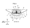
- Fig. 3 is a cross section along line B-B of Fig. 2 .
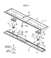
- Fig. 4 is an overall exploded perspective view obtained by viewing obliquely from above, namely, from a ceiling side the lighting apparatus according to the present embodiment of the present invention.
- a ceiling side is designated to be an upward direction
- a floor side is designated to be a downward direction. That is, when the lighting apparatus 1 is attached to the ceiling 2, it is done so in an order of an apparatus body 3 and a light emitter unit 4 from the top down. Further, since the lighting apparatus 1 has an outer shape of a substantially rectangular parallelepiped, the lighting apparatus 1 has six faces.
- a face of the lighting apparatus 1 toward the ceiling is called a top face
- a face of the lighting apparatus 1 toward the floor is called a bottom face
- a longitudinal face of the long lighting apparatus 1 orthogonal to the ceiling 2 is called a longitudinal direction side face
- a short face of the long lighting apparatus 1 which is other than the top face, the bottom face, and the longitudinal direction side face and orthogonal to the ceiling 2 is called a short-direction side face.
- a direction that is parallel to the ceiling 2 and parallel to the longitudinal direction side face is called a longitudinal direction and a direction that is parallel to the ceiling 2 and parallel to the short-direction side face is called a short direction.
- the lighting apparatus 1 of the present embodiment includes the apparatus body 3 fixed on a lower face of the ceiling 2 and the attachable and detachable light emitter unit 4 which is provided underneath the apparatus body 3, contains, for example, an LED (light-emitting diode) as a light source, and is equipped with a translucent cover 5 that transmits or diffuses light for its bottom face.
- an LED light-emitting diode
- the apparatus body 3 is a long, substantially rectangular parallelepiped, and a pair of spring receiving pieces 6 is arranged facing down along a center line in the longitudinal direction and is fixed on the apparatus body 3 with screws 30.
- a feeding connector 8a is provided at one end of a first cable 7a for supplying power to the light emitter unit 4 and the feeding connector 8a is extended downward through the apparatus body 3 from the ceiling 2 via the first cable 7a.
- the apparatus body 3 is fixed on the ceiling 2 from the downside using, for example, screws and/or hooks (not illustrated).
- FIG. 3 and 4 An example of a shape of the apparatus body 3 is illustrated in Figs. 3 and 4 , where a portion facing to the light emitter unit 4 is concave in the short-direction cross section to take a shape so that a part of the light emitter unit 4 comes into engagement with the apparatus body 3; then, the amount of downward projection of the lighting apparatus 1 from the ceiling 2 becomes small and so that thinning of it is preferably realized.
- the light emitter unit 4 includes a light emitter base 9 which is formed, for example, in a substantially U-shaped cross section by bending both sides of longitudinal-direction side faces made of an iron sheet, a light emitter substrate 10 that is provided along a bottom face of the light emitter base 9, and light emitting elements 11, which are LEDs, for example, that are electrically connected to the light emitter substrate 10 and are provided on a bottom face side of the light emitter substrate 10.
- a power supply device 12 that is electrically connected to the light emitter substrate 10 is provided on the top face of the light emitter base 9; a receiving connector 8b is provided on one end of a second cable 7b extended from the power supply device 12 and is paired with the feeding connector 8a provided on one end of the first cable 7a extended downward from the ceiling 2 through the apparatus body 3 to be connectable with each other so that, when the connectors 8a and 8b are connected to each other, the light emitting elements 11 can emit light through the light emitter substrate 10 by supplying power from the power supply device 12.
- a bottom face of the light emitter unit 4 is covered with a translucent cover 5 that transmits light from the light emitting elements 11.
- a translucent cover 5 that transmits light from the light emitting elements 11.
- catching parts 13 in which end parts are bent inward toward each other are provided so that a construction is provided in which they are brought into engagement with the end parts of the substantially U-shaped cross section of the light emitter base 9 from the outside to hold the translucent cover 5 to the light emitter base 9.
- the translucent cover 5 may transmit light from the light emitting elements 11 and may be made of transparent materials or semi-transparent materials. Further, the translucent cover 5 may be diffusive or non-diffusive. When the translucent cover 5 is diffusive, uniformity would be good whereas efficiency would be improved when it is non-diffusive.
- spring holders 15 are fixed, for example, using the screws 30 at positions corresponding to the spring receiving pieces 6 provided downward on the apparatus body 3.
- the spring holder 15 penetrates an inside of a coil part 17 of a torsion spring 16 that is wound cylindrically and supports the torsion spring 16 to the light emitter base 9. Both ends of the coil part 17 of the torsion spring 16 form a pair of spring arm parts 18 extending substantially symmetrically.
- the torsion spring 16 may be hereinafter referred to as a kick spring 16 in the description of the present invention.
- the spring holder 15 need not tightly fix the coil part 17 of the kick spring 16 with respect to the light emitter base 9 and may be in a state with a backlash. On the spring holder 15, folded parts 28 that restrict a movement of the kick spring 16 in the short direction are provided.
- the spring holder 15 that penetrates and holds the coil part 17 of the kick spring 16, and the spring receiving piece 6 that acts with the spring arm parts 18 of the kick spring 16 will be described.
- the spring holder 15 provided on the light emitter base 9 and the spring receiving piece 6 provided on the apparatus body 3 are located at mutually corresponding positions, so that the spring arm parts 18 of the kick spring 16 the coil part 17 of which is supported by the spring holder 15 are brought into engagement with spring receiving grooves 19 and a spring force, namely, the biasing force generated by the kick spring 16 acts on the spring receiving grooves 19.
- cut-and-raised parts 20, which act as so-called stoppers, that restrict a movement of the coil part 17 of the kick spring 16 in the short direction are provided and hold the kick spring 16 on a substantially center line in the longitudinal direction of the light emitter unit 4.
- two kick springs 16 are provided on the center line in the longitudinal direction of the light emitter unit 4, and are mutually arranged to put a position of the center of gravity G of the light emitter unit 4 between them.
- the position of the center of gravity G of the light emitter unit 4 is generally located in the vicinity of the center position in the longitudinal direction; when the power supply device 12 is arranged away from the center position of the light emitter unit 4, the position of the center of gravity G is a position deviated toward the power supply device 12 from the center position in the longitudinal direction.
- the present embodiment has a configuration in which a cross section shape in the short direction is substantially symmetric and, therefore, the position of the center of gravity G of the light emitter unit 4 is located on the center line in the longitudinal direction and the upward biasing force due to the kick springs 16 are configured to bias the center of gravity of the light emitter unit 4 upward.
- a pair of the kick springs 16 is mutually arranged to put the position of the center of gravity G of the light emitter unit 4 therebetween and, therefore, a spring force due to the kick springs 16 can stably bias the light emitter unit 4 upward to hold it in contact with the apparatus body 3.
- the apparatus body 3 As a construction process at the time of attaching the light emitter unit 4 to the apparatus body 3, the apparatus body 3 is attached to the ceiling and it is situated that the feeding connector 8a is hung from the apparatus body 3 via the first cable 7a.
- the two kick springs 16 are arranged on the center line in the longitudinal direction of the light emitter unit 4 with the position of the center of gravity G of the light emitter unit 4 being put therebetween and, therefore, the light emitter unit 4 is hung down in a position substantially parallel to the apparatus body 3.
- the feeding connector 8a that is hung down from the apparatus body 3 and the receiving connector 8b connected via the second cable 7b to the power supply device 12 provided on the light emitter unit 4 are connected to each other.
- the lighting apparatus 1 is preferable to have a configuration with the following effects, as being easily constructed:
- the lighting apparatus 1 has the above-described effects, and a detailed configuration will be described below.
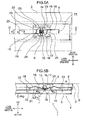
- Fig. 5A shows an arrow view in the direction C of Fig. 2
- Fig. 5B shows a cross section of Fig. 5A along line D-D.
- Figs. 5A and 5B illustrate a state in which the light emitter unit 4 is set to the apparatus body 3.
- Fig. 6A shows a perspective view obtained by viewing obliquely from below the lighting apparatus according to the embodiment of the present invention, which illustrates a state in which the light emitter unit 4 is hung down by the kick springs 16, and Fig. 6B shows a perspective view illustrating a configuration in the vicinity of the kick spring of Fig. 6A in detail.
- the spring holder 15 is inserted into the inside of the cylindrical coil part 17 of the kick spring 16, which is a torsion spring, and the spring holder 15 is fixed on the top face of the light emitter base 9, thereby attaching the kick spring 16 to the light emitter unit 4.
- a center axis of the coil part 17 of the kick spring 16 is supported while being directed in the short direction.
- Both ends of the kick spring 16 have a pair of the spring arm parts 18 extending in a tangential direction away from the coil part 17.
- Each of the spring arm parts 18 has a first bending corner 21 that is generally provided in the vicinity of the center of the spring arm part 18 and is bent in a direction away from the center axis of the coil part 17 as a distance from the coil part 17 increases, and a second bending corner 22 that is provided in the vicinity of the end of the spring arm part 18 opposite to the coil part 17 with respect to the first bending corner 21 and is bent in a direction opposite to the first bending corner 21.
- the end of the spring arm part 18 has a stopper part 23 of a width s that is bent toward the coil part 17 in parallel to the center line of the coil part 17. In this stopper part 23, the end may be further bent by 180° to provide a round tip so that burrs on a cutting surface of materials can be prevented from being exposed to the end.
- a pair of the spring arm parts 18 extending from both ends of the coil part 17 is arranged as being separated from each other by e and each of the spring arm parts 18 rotates around the center axis of the coil axis 17; therefore, planes in which a pair of the spring arm parts 18 rotates respectively exist along the longitudinal vertical directions while they are separated from each other by e.
- a pair of the spring arm parts 18 has a shape of rotational symmetry with which, when viewed from above as illustrated in Fig. 5A , it becomes substantially the same shape upon being rotated by 180°.
- the spring receiving piece 6 has a pair of the spring receiving grooves 19 corresponding to a pair of the spring arm parts 18 of the kick spring 16.
- a pair of the spring receiving grooves 19 corresponds to a pair of the spring arm parts 18; they are located with a gap of e from each other and, when viewed from above as illustrated in Fig. 5A , they are provided at positions of rotational symmetry with which the shape becomes substantially the same upon being rotated by 180°.
- the spring receiving groove 19 contacts with the spring arm part 18 in a section from the coil part 17 to the first bending corner 21 and receives the biasing force from the kick spring 16.
- the spring arm parts 18 In the state in which the kick spring 16 is detached and torque is not applied, the spring arm parts 18 have a shape as illustrated in a broken line of Fig. 5B while, when the light emitter unit 4 is set to the apparatus body 3, elastic deformation is caused and a torque is generated in a direction illustrated with arrows.
- a direction of the force Fa is perpendicular to a direction in which the spring arm part 18 contacts with the spring receiving groove 19, and is inclined by an angle of ⁇ a with respect to the vertical direction. Accordingly, a component of an upward force in the vertical direction against the light emitter unit 4 is Fa ⁇ cos( ⁇ a) and, since there are two spring arm parts 18 for each of the kick springs 16, a force lifting up the light emitter unit 4 is 2 ⁇ Fa ⁇ cos( ⁇ a) per each of the kick springs 16.
- a force pulling up the light emitter unit 4 is 4 ⁇ Fa ⁇ cos( ⁇ a) in total.
- a mass of the light emitter unit 4 be m and the gravitational acceleration be g, in order to set the light emitter unit 4 in contact with the apparatus body 3 against the own weight, it is preferable to hold a relationship in which the sum of the forces due to a pair of the kick springs 16 4 ⁇ Fa ⁇ cos( ⁇ a) is greater than the force mg due to the own weight (4 ⁇ Fa ⁇ cos( ⁇ a) > mg).
- both the distance between a pair of the spring arm parts 18 and a gap between the spring receiving grooves 19 are set to be the same dimension of e, even when the light emitter unit 4 is moved downward and the kick spring 16 is subjected to torsional displacement, the center axis of the coil part 17 of the kick spring 16 stays directed to the short direction. Accordingly, a relationship between the center axis of the coil part 17 and the spring holder 15 is not changed and the kick spring 16 is always supported in a stable manner. That is, even when the light emitter unit 4 is moved vertically during the construction, the kick spring 16 will not rotate or swing when viewed from above as illustrated in Fig. 5A .
- a torsion spring is generally accompanied by a twist angle so-called a lead angle for winding its coil part 17
- a pair of the spring arm parts 18 is not parallel to each other but has a shape opened more toward the ends. Needless to say, even if it takes the above-described shape so that a distance between the respective spring arm parts 18 is different from the gap e between the spring receiving grooves 19, effects according to the present embodiment are similarly obtained as long as it is in the range of elastic deformation of the spring arm parts 18.
- the feeding connector 8a that is provided to the first cable 7a extending from the apparatus body 3 on the ceiling side and the receiving connector 8b that is provided to the second cable 7b extending from the power supply device 12 provided on the light emitter unit 4 are connected with each other.
- an inclined part 25 is provided so that a distance between the cut-and-raised part 20 adjacent to the spring receiving groove 19 and a side facing against the cut-and-raised part 20 with respect to the spring receiving groove 19 becomes narrower toward the spring receiving groove 19.
- Fig. 7 shows a cross section of Fig. 6A along line B'-B' and illustrates a state in which the light emitter unit 4 is hung down via the kick spring 16.
- the B'-B' line cross section is a cross section at the same position as the B-B line cross section of Fig. 2 .
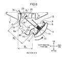
- Fig. 8 shows a cross section of Fig. 6A along line B'-B' like Fig. 7 : it however illustrates a state in which the light emitter unit 4 is swung toward the back side in the short direction while it is hung down with the kick spring 16.
- a state is illustrated in which the light emitter unit 4 is hung down from the apparatus body 3 with two of the kick springs 16 and is lowered down by u3 from the set state illustrated in Fig. 3 .
- the kick springs 16 are arranged on the center line in the longitudinal direction of the light emitter unit 4 and, in particular, the center of gravity of the light emitter unit 4 is provided within the range of the width e of the spring receiving grooves 19 on which the kick springs 16 are hooked, so that the light emitter unit 4 is stably supported while keeping horizontal even in the state in which the light emitter unit 4 is hung down.
- a gap p1 between the apparatus body 3 and the light emitter unit 4 is equivalent to or slightly smaller than a length of the spring arm part 18 of the kick spring 16.
- the light emitter unit 4 when the light emitter unit 4 is pushed toward the back side from the front side in the short direction, it swings toward the back side with the stopper part 23 of the kick spring 16 as the center, which is hooked onto the spring receiving piece 6 provided approximately on the center line in the longitudinal direction of the apparatus body 3, to yield a mode illustrated in Fig. 8 .
- the stopper part 23 of the kick spring 16 can be tilted upward from the spring receiving piece 6 with the position of the spring receiving groove 19 as the center.
- a relationship between a thickness h of the spring receiving piece 6 in the vertical direction and a length s of the stopper part 23 of the kick spring 16 holds h>s, even when the kick spring 16 is tilted along with the light emitter unit 4, the stopper part 23 will not be pushed or pried in contact with the apparatus body 3, thereby the light emitter unit 4 being easily inclined.
- the light emitter unit 4 has a construction which can be tilted around the stopper parts 23 at the ends of the kick springs 16 while staying close to the apparatus body 3.
- a gap p2 between the apparatus body 3 and the light emitter unit 4 at the time of the light emitter unit 4 being tilted toward the back side is larger than the gap p1 in the state being hung down straight as illustrated in Fig. 7 , and p2>p1 holds.
- the connector pair 8 and the cables 7a, 7b are easily viewed and work is easily performed.
- the light emitter unit 4 when the connector pair 8 is engaged, the light emitter unit 4 can be tilted toward the back side in the short direction and a room in front can be enlarged; therefore, there is an advantageous effect that the lighting apparatus that is easily viewed and constructed can be provided.
- Fig. 9A shows a cross section in the longitudinal direction illustrating a state in which the light emitter unit 4 is set to the apparatus body 3, like Fig. 3 .
- Figs. 9B to 9D show cross sections in the longitudinal direction illustrating positions in which the light emitter unit 4 is pulled down by distances of u1, u2, and u3, respectively.
- Fig. 9E shows a cross section in the longitudinal direction illustrating an operation at the time when the kick spring 16 is elastically deformed to attach to the spring receiving piece 6.
- a force Fa is exerted to the spring receiving piece 6 from the spring arm part 18 of the kick spring 16 in a direction of an angle ⁇ a from the vertical direction and the light emitter unit 4 having a mass m is biased toward the apparatus body 3 above. Further, in this state, a distance between the apparatus body 3 and the light emitter base 9 is H and a construction is desirable with which this dimension H can be reduced to thin the lighting apparatus 1.
- Fig. 9B illustrates a position in which the light emitter unit 4 is pulled down from the set state by a distance u1; it is a state where a point between the coil part 17 and the first bending corner 21 in the spring arm part 18 is engaged on the spring receiving piece 6, and a force Fb is applied in a direction of an angle ⁇ b from the vertical direction to bias the light emitter unit 4 of the mass m toward the apparatus body 3 above.
- Fig. 5B when the relationship (4 ⁇ Fb ⁇ cos( ⁇ b) > mg) holds, an upward biasing force due to the kick springs 16 is larger than the own weight of the light emitter unit 4 and therefore the light emitter unit 4 is in a state of being biased upward.
- the first bending corner 21 and the second bending corner 22 are provided to the spring arm part 18, there is an advantageous effect that the dimension H can be reduced so as to implement thinning of the lighting apparatus 1.
- the first bending corner 21 and the second bending corner 22 are bent in an opposite direction with each other, it is the first bending corner 21 that contributes to the effect of reducing the dimension H and it is effective that the first bending corner 21 is provided in the vicinity of the approximate center of the spring arm part 18.
- Fig. 9C illustrates a position in which the light emitter unit 4 is further pulled down to a distance u2; it is a state where the first bending corner 21 of the spring arm part 18 is engaged on the spring receiving piece 6, and a force Fc is applied in a direction of an angle ⁇ c from the vertical direction to bias the light emitter unit 4 of the mass m toward the apparatus body 3 above.
- ⁇ c ⁇ ⁇ b holds due to the first bending corner 21 and cos( ⁇ b) ⁇ cos( ⁇ c); therefore, the upward component in the vertical direction of the force Fc becomes even greater and a force pulling up the light emitter unit 4 becomes greater.
- Fig. 9D illustrates a state in which the light emitter unit 4 is further pulled down to a distance u3 and is hung down like Fig. 7 .
- the stopper parts 23 at the ends of the spring arm part 18 are engaged onto the cut-and-raised parts 20 of the spring receiving piece 6, and the second bending corners 22 provided to the spring arm parts 18 are located lower than the spring receiving piece 6.
- it is a state where the spring receiving piece 6 supports a portion closer to the ends of the spring arm parts 18 than the second bending corners 22.
- the spring arm parts 18 are bent at the second bending corners 22 in a direction opposite to that at the first bending corners 21 and, in the hanging state illustrated in Fig. 9D , an angle ⁇ d becomes larger so that a direction of a force Fd becomes closer to the horizontal, and a component in the vertical direction thereof Fd ⁇ cos( ⁇ d) becomes smaller.
- the force Fd and the angle ⁇ d are determined so that 4 ⁇ Fd ⁇ cos( ⁇ d) ⁇ mg holds, the light emitter unit 4 won't be raised up by the biasing forces of the kick springs 16 but the hanging state of the light emitter unit 4 can be kept as is in a state as illustrated in Fig. 9D or Figs. 6A , 6B , and 7 .
- the light emitter unit 4 can be held in a state of being hung down by the kick springs 16 and no special hanging members such as strings or chains are necessary, thereby yielding an advantageous effect that a lighting apparatus with ease of construction can be provided.
- Fig. 9E illustrates operations at the time when a pair of the spring arm parts 18 of the kick spring 16 is deformed elastically with fingers to bring them close to each other in a direction of the white arrows, and the stopper parts 23 at the ends of the kick spring 16 are attached to the spring receiving piece 6 from below.
- the light emitter unit 4 can be easily detached from the apparatus body 3.
- the stopper parts 23 at the ends of the spring arm parts 18 are slipped into a hole 24 provided in the spring receiving piece 6 from underneath and are attached to the spring receiving grooves 19 while the kick spring 16 is elastically deformed with fingers as illustrated in Fig. 9E , and the light emitter unit 4 is rendered to be hung down from the apparatus body 3 via the kick spring 16 as illustrated in Fig. 9D .
- special hanging means such as strings or chains are not required to keep the hanging state.
- Fig. 10 is a cross section along the longitudinal direction A-A exemplifying an attaching or detaching operation of the light emitter unit 4.
- Fig. 10 shows a state in which only one of the kick springs 16 is hooked onto the spring receiving piece 6 in the middle of the construction.
- the biasing forces Fd from the kick spring 16 to the spring receiving piece 6 are generated from a pair of the spring arm parts 18 mutually symmetric in the longitudinal direction and the forces are balanced in the longitudinal direction. Accordingly, in a state where only one kick spring 16 shown in the right in the figure is hooked on the spring receiving piece 6 as illustrated in Fig. 10 , the kick spring 16 does not generate the biasing force in the longitudinal direction onto the light emitter unit 4.
- the light emitter unit 4 is stably located with the spring holder 15 straight under the spring receiving piece 6 via one of the kick springs 16 which had been hooked up already, thereby providing an advantageous effect that a position of the light emitter unit 4 is stable to easily hook the other kick spring 16.
- first bending corners 21 are provided on the spring arm parts 18 of the kick spring 16, gaps 26 are created between the first bending corners 21 and the light emitter base 9.
- the kick spring 16 is easily deformed elastically up to the state illustrated in Fig. 9E and, therefore, an attaching operation of the light emitter unit 4 is facilitated.
- a lighting apparatus which is easily constructed in a way that, when only one kick spring 16 is hooked up in the middle of construction, the light emitter unit 4 is easily supported and the second kick spring 16 is easily hooked up so that the light emitter unit 4 can be attached and detached without using any special tools.
- FIG. 11 shows a cross section illustrating the lighting apparatus according to a second embodiment of the present invention along line B-B in the short direction like Fig. 3 .
- the second embodiment differs from the first embodiment in that a width W2 in the short direction of the apparatus body 3 is approximately equal to a width W1 of the light emitter unit 4. Since the kick springs 16 and the spring receiving pieces 6 for biasing the apparatus body 3 and the light emitter unit 4 are located on the top face of the light emitter unit 4 on the center line in the longitudinal direction, the width W2 in the short direction of the apparatus body 3 can be reduced down to a dimension approximately equal to the width W1 of the light emitter unit 4.
- a lighting apparatus which is easily constructed as the light emitter unit 4 can be attached and detached without using any special tools while the light emitter units 4 can be arranged close to each other in the short direction.
- FIGS. 12A and 12B show cross sections along line A-A of the longitudinal direction exemplifying an attaching or detaching operation of the light emitter unit 4 of the lighting apparatus according to the third embodiment of the present invention.
- Fig. 12A illustrates a state where the light emitter unit 4 is set to the apparatus body 3 like Fig. 2
- Fig. 12B illustrates a state where only one kick spring 16 is hooked up on the spring receiving piece 6 so that the light emitter unit 4 is hung down from the apparatus body 3.
- the third embodiment differs from the first embodiment in that three sets of the kick springs 16, the spring holders 15, and the spring receiving pieces 6 for biasing the apparatus body 3 and the light emitter unit 4 are provided along the center line in the longitudinal direction. Among them, two sets are arranged in the vicinity of both ends in the longitudinal direction, and a set of the kick spring 16c is arranged near the center in the longitudinal direction.
- the position of the center of gravity of the light emitter unit 4 is a position closer to the power supply device 12 than to the center position in the longitudinal direction.
- a position of the kick spring 16c that is arranged near the center of the longitudinal direction is not the center position in the longitudinal direction, but it is arranged to a position in which L1 ⁇ L2 holds where L1 and L2 are dimensions from end faces in the longitudinal direction of the light emitter unit 4 on the side of the power supply device 12 and on the opposite side, respectively.
- the kick spring 16c in the center is arranged in the vicinity of the position of the center of gravity of the light emitter unit 4 and, therefore, the light emitter unit 4 is supported substantially horizontally when only the center kick spring 16c is hooked on the corresponding spring receiving piece 6 as illustrated in Fig. 12B ,.
- the connector pair 8 may be engaged in this state.
- the kick springs 16 provided near respective ends in the longitudinal direction of the light emitter unit 4 are easily hooked up on the respective corresponding spring receiving pieces 6 sequentially and, when the three kick springs 16 are hooked up on the respective corresponding spring receiving pieces 6, the light emitter unit 4 is in a state of being hung down from the apparatus body 3 with the three kick springs 16.
- the connector pair 8 is engaged, when the light emitter unit 4 is lifted up, it is set due to the biasing force by the kick springs 16 as illustrated in Fig. 12A .
- the third embodiment has a configuration in which the light emitter unit 4 is hung down and supported by three of the kick springs 16 that are arranged in the longitudinal direction and the kick spring 16c provided in the center is arranged in the vicinity of the center of gravity of the light emitter unit 4; therefore, even when only the center kick spring 16c is hooked up, the light emitter unit 4 is supported substantially horizontally and engagement of the connector pair 8 and hooking up of the two kick springs 16 near respective ends in the longitudinal direction are easy, thereby providing a lighting apparatus which is easily constructed such that the light emitter unit 4 can be attached and detached without using any special tools.
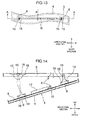
- Fig. 13 shows a schematic top view in which a lighting apparatus 1 according to the fourth embodiment of the present invention is viewed from the ceiling 2 side.
- the fourth embodiment differs from the first embodiment in that the apparatus body 3 and the light emitter unit 4 are not straight in the longitudinal direction but curved entirely or partially while a cross section along line A-A in the longitudinal direction has the same configuration as that of Fig. 2 .
- a mode of bending in a substantially S-shape in the longitudinal direction is illustrated as an example of the fourth embodiment.
- a pair of the kick springs 16 is arranged near respective ends in the longitudinal direction of the light emitter unit 4 to put the position of the center of gravity G therebetween and the center lines of the cylindrical coil parts 17 of a pair of the kick springs 16 are arranged so as to be parallel to each other. Further, it is desirable that the position of the center of gravity G is provided within the range of e which is a distance between the spring arm parts 18 of the kick spring 16 since the light emitter unit 4 can be stably supported.
- the light emitter unit 4 can be biased to set to the apparatus body 3 with the biasing force of the kick springs 16; further, the light emitter unit 4 can be hung down horizontally like Fig. 7 and the light emitter unit 4 can be swung like Fig. 8 . Accordingly, engagement of the connector pair 8 and hooking up of the kick springs 16 are easy, thereby providing a lighting apparatus which is easily constructed such that the light emitter unit 4 can be attached and detached without using any special tools.
- Fig. 13 an example in which the apparatus body 3 and the light emitter unit 4 are curved in a substantially S-shape is illustrated in Fig. 13 ; however, it is not limited to such the shape and may be in a partial arc-shape, a chevron-shape, or a shape to include a plurality of bendings in the longitudinal direction, and it goes without saying that the same effects can be obtained.
- a kick spring 16c is further provided on a substantially center part of the light emitter unit 4.
- Fig. 14 shows a cross section along line A-A in the longitudinal direction exemplifying attaching or detaching operation of a light emitter unit 4 of a lighting apparatus 1 having a configuration different from that of the present invention and illustrates a state in which only one of two kick springs 16 is hooked on the spring receiving piece 6 like Fig. 10 .
- the spring holders 15 that hold the kick springs 16 are attached to the apparatus body 3 and the spring receiving pieces 6 are provided on the light emitter base 9 of the light emitter unit 4.
- the spring receiving pieces 6 cannot be observed from down below behind the light emitter unit 4 during construction. Accordingly, operations of inserting and hooking the ends of the spring arm parts 18 of the kick spring 16 into and on the spring receiving grooves 19 provided on the spring receiving piece 6 are performed without being viewed and, therefore, a problem may arise in terms of workability.
- Fig. 15 shows a cross section along line A-A in the longitudinal direction exemplifying attaching or detaching operation of a light emitter unit 4 of a lighting apparatus 1 having a configuration further different from that of the present invention and illustrates a state in which only one of two kick springs 16 is hooked on the spring receiving piece 6 like Fig. 10 .
- a pair of the spring arm parts 18 of the kick spring 16 is not provided symmetrically, but a spring arm part 18 is provided on only one side of the kick spring 16; the other end part 27 is brought into contact with the light emitter base 9 so that it is configured that only one spring arm part 18 is hooked onto a corresponding spring receiving piece 6.
- the light emitter unit 4 receives a reactive force Q in the longitudinal direction from the spring receiving groove 19 due to the kick spring 16 and this force acts to move the light emitter unit 4 in the longitudinal direction.
- the lighting apparatus according to the present invention has a configuration in which the kick spring 16 of the torsion spring that biases the light emitter unit 4 toward the apparatus body 3 attached to the ceiling 2 is provided in a plurality along the center line in the longitudinal direction on the top face of the light emitter unit 4, the spring receiving pieces 6 corresponding to the respective kick springs 16 are provided on the apparatus body 3 facing downward, and the kick springs 16 are hooked onto the spring receiving pieces 6 so that the light emitter unit 4 is brought into contact with the apparatus body 3, thereby providing a lighting apparatus with ease of hooking the kick springs 16 onto the spring receiving pieces 6 and with ease of construction since the spring receiving pieces 6 can be seen during construction from below.
- the light emitter unit 4 can be held as being hung down via the kick springs 16 and, therefore, the light emitter unit 4 need not be hung down using special hanging members such as strings or chains during engaging the connector pair 8, so that a lighting apparatus in which the light emitter unit 4 is attachable and detachable without using any special tools can be obtained with a simple construction.
- the light emitter unit 4 can be swung in the short direction while the light emitter unit 4 is hung down via the kick springs 16 and, therefore, when the light emitter unit 4 is swung toward the back side, a space for engaging the connector pair 8 is large in front and the spring receiving pieces 6 are viewed more easily, so that a lighting apparatus with ease of construction can be obtained.
- the light emitter unit 4 can simply be lifted up from being hung down so that the light emitter unit 4 is pulled up toward the apparatus body 3 by the biasing force by the kick springs 16 and set and, therefore, a lighting apparatus with ease of construction in which the light emitter unit 4 can be attached without using any special tools can be obtained.
- a pair of the spring arm parts 18 of the kick spring 16 is made in a symmetrical shape with respect to the coil part 17 of the spring and the spring receiving grooves 19 corresponding to the respective spring arm parts 18 are provided in the spring receiving piece 6 and, therefore, even if only one of a plurality of the kick springs 16 is hooked onto the spring receiving piece 6, a force moving the light emitter unit 4 in the longitudinal direction is not generated and the light emitter unit 4 can be stably hung down, so that a lighting apparatus with ease of construction can be obtained.
- the inclined part 25 is provided to make the distance narrower toward the spring receiving groove 19 with the sides and the cut-and-raised part 20 adjacent to the spring receiving groove 19 provided in the spring receiving piece 6 and, therefore, when the kick spring 16 is attached, the spring arm parts 18 are guided and attracted into the spring receiving grooves 19 along the cut-and-raised parts 20 and/or the inclined parts 25 so that a lighting apparatus in which the kick springs 16 can be securely and easily attached to the spring receiving grooves 19, the kick springs 16 are easily attached, and the construction is easily performed can be obtained.
- the width dimension of the apparatus body 3 in the short direction can be made approximately equal to the width dimension of the light emitter unit 4 in the short direction and, therefore, a plurality of lighting apparatus can be arranged adjacently in the short direction.
- the three kick springs 16 are provided in a lighting apparatus 1 that is particularly long in the longitudinal direction, and one of them is arranged in the vicinity of the position of the center of gravity in the substantially center of the light emitter unit 4 and, therefore, even when only the kick spring 16c in the vicinity of the center is hooked onto the spring receiving piece 6, the light emitter unit 4 can be stably hung down substantially horizontally so that a lighting apparatus with ease of construction can be obtained.
- the lighting apparatus according to the present invention can be held with the light emitter unit 4 hung down via the kick springs 16, even if the apparatus body 3 and the light emitter unit 4 are not linear in the longitudinal direction but constructed with curves entirely or partially, by arranging a pair of the kick springs 16 in the vicinity of both ends in the longitudinal direction of the light emitter unit 4 to put the position of the center of gravity G therebetween with center lines of the coil parts 17 parallel to each other and providing the position of the center of gravity G within the range of e that is a distance between the spring arm parts 18 of the kick spring 16 so that a lighting apparatus with ease of construction can be obtained.
- the light emitting elements 11 as light sources are described with LEDs; however, the light emitting elements 11 are not limited to the LEDs, and OLEDs (organic light emitting diodes) may be used.
- a pair of the kick springs 16 is arranged on the center line of the longitudinal direction of the light emitter unit 4, it is not limited to such the arrangement; even when one of the kick springs 16 may be arranged with a shift toward the front in the short direction and the other kick spring 16 may be arranged with a shift toward the back in the short direction, as long as a pair of the kick springs 16 is arranged to put the center of gravity therebetween, the light emitter unit 4 can be stably held and it yields the same effects as those of the present embodiments.
Landscapes
- Engineering & Computer Science (AREA)
- General Engineering & Computer Science (AREA)
- Non-Portable Lighting Devices Or Systems Thereof (AREA)
Abstract
Description
- The present invention relates to a lighting apparatus attached to a ceiling part.
- In
JP-A-H6-309912 lighting fixture body 1 is installed as embedded in a ceiling part, and abody frame part 2 is fixed to thelighting fixture body 1, and thelighting fixture body 1 and thebody frame part 2 are locked by locking means 31 to 34 which are springs. Further, one-side ends of the locking means 31 to 34 are fixed toward thebody frame part 2, and the other ends of the locking means 31 to 34 are formed toward thelighting fixture body 1 as being attachable and detachable; avoiding means 41 to 48 are provided to prevent the locking means 31 to 34 from abutting on ceiling constituent members when thelighting fixture body 1 and thebody frame part 2 are locked by the locking means 31 to 34". - In the configuration disclosed in
JP-A-H6-309912 body frame part 2 detachable while being hung down from thelighting fixture body 1 fixed to the ceiling part by the locking means 31 to 34 is not a light emitter unit including light emitting elements or light emitters, and a total of four sets of the locking means (kick springs as biasing means) 31 to 34 are provided along two sides of thebody frame part 2 as two sets each on a side surface. Further, when thebody frame part 2 is attached to thelighting fixture body 1, the locking means 31 to 34 are sequentially inserted one by one into the avoiding means 41 to 48, which are long narrow slits, and therefore attaching operation of the kick springs is required four times, which is troublesome and becomes a problem to be solved. - In view of the foregoing problem, it is an object of the present invention to provide a lighting apparatus with which attaching operation of a light emitter unit is facilitated.
- To attain the above object, a configuration described in claims is, for example, adopted.
- As an example, it includes an apparatus body that is attached to a ceiling; and a light emitter unit which is provided attachable and detachable under the apparatus body and has a light emitter substrate that includes a light emitting element, a power supply device that is connected to the light emitter substrate, a translucent cover that covers a lower part of the light emitter substrate and transmits light irradiated from the light emitting element, and a pair of biasing members that is arranged on an top face opposite to the translucent cover in the light emitter unit putting a position of the center of gravity of the light emitter unit therebetween, each of the pair of biasing members being a torsion spring including a coil part that is wound in a cylindrical form and a pair of arm parts that is extending from both ends of the coil part, the pair of biasing members being arranged with center axes of the coil parts parallel to each other, the pair of biasing members being respectively attachable to and detachable from spring receiving pieces provided on the apparatus body.
- According to the present invention, a lighting apparatus with which attaching operation of the light emitter unit is facilitated can be obtained.
- Other objects, features, and advantages of the invention will become apparent from the following description of the embodiments of the invention taken in conjunction with the accompanying drawings.
-
-
Fig. 1 shows a perspective view obtained by viewing obliquely from below a lighting apparatus according to a first embodiment of the present invention; -
Fig. 2 shows a cross section ofFig. 1 along line A-A; -
Fig. 3 shows a cross section ofFig. 2 along line B-B; -
Fig. 4 shows an overall exploded perspective view obtained by viewing obliquely from above a lighting apparatus according to an embodiment of the present invention; -
Fig. 5A shows an arrow view in the direction C ofFig. 2 , andFig. 5B shows a cross section ofFig. 5A along line D-D; -
Fig. 6A shows a perspective view obtained by viewing obliquely from below a lighting apparatus according to an embodiment of the present invention, which illustrates a state in which a light emitter unit is hung down by kick springs, andFig. 6B shows a perspective view illustrating a configuration in the vicinity of the kick spring ofFig. 6A in details; -
Fig. 7 shows a cross section ofFig. 6A along line B'-B' and illustrates a state in which the light emitter unit is hung down by the kick springs; -
Fig. 8 shows another cross section ofFig. 6A along line B'-B' and illustrates a state in which the light emitter unit is swung toward the back side in the short direction while being hung down by the kick springs; -
Figs. 9A to 9E show schematic cross sections illustrating stepwise an attaching or detaching operation of the light emitter unit of the lighting apparatus according to the first embodiment of the present invention; -
Fig. 10 shows a cross section along line A-A exemplifying an attaching or detaching operation of the light emitter unit of the lighting apparatus according to the first embodiment of the present invention; -
Fig. 11 shows a cross section illustrating the lighting apparatus according to a second embodiment of the present invention along a line similar to line B-B ofFig. 3 ; -
Figs. 12A and 12B show cross sections along line A-A exemplifying attaching or detaching operation of a light emitter unit of a lighting apparatus according to a third embodiment of the present invention; -
Fig. 13 shows a schematic top view in which a lighting apparatus according to a fourth embodiment of the present invention is viewed from a ceiling side; -
Fig. 14 shows a cross section along line A-A exemplifying attaching or detaching operation of a light emitter unit of a lighting apparatus having a configuration different from that of the present invention; and -
Fig. 15 shows a cross section along line A-A exemplifying attaching or detaching operation of a light emitter unit of another lighting apparatus having a configuration further different from that of the present invention. - Hereinafter, examples of embodiments of the present invention will be described in detail with reference to the accompanying drawings. Incidentally, in respective drawings, the same reference numeral is given to the common part and descriptions will be omitted.
- First, a configuration of a
lighting apparatus 1 according to a first embodiment will be described with reference toFigs. 1 to 4 .Fig. 1 shows a perspective view obtained by viewing obliquely from below the lighting apparatus according to the first embodiment of the present invention.Fig. 2 shows a cross section along line A-A ofFig. 1 .Fig. 3 is a cross section along line B-B ofFig. 2 .Fig. 4 is an overall exploded perspective view obtained by viewing obliquely from above, namely, from a ceiling side the lighting apparatus according to the present embodiment of the present invention. - Suppose here that at the time when the
lighting apparatus 1 is attached to aceiling 2, a ceiling side is designated to be an upward direction, and a floor side is designated to be a downward direction. That is, when thelighting apparatus 1 is attached to theceiling 2, it is done so in an order of anapparatus body 3 and alight emitter unit 4 from the top down. Further, since thelighting apparatus 1 has an outer shape of a substantially rectangular parallelepiped, thelighting apparatus 1 has six faces. Hereinafter, taking a state where thelighting apparatus 1 is attached to theceiling 2 as reference, a face of thelighting apparatus 1 toward the ceiling is called a top face, a face of thelighting apparatus 1 toward the floor is called a bottom face, a longitudinal face of thelong lighting apparatus 1 orthogonal to theceiling 2 is called a longitudinal direction side face, and a short face of thelong lighting apparatus 1 which is other than the top face, the bottom face, and the longitudinal direction side face and orthogonal to theceiling 2 is called a short-direction side face. Also, hereinafter a direction that is parallel to theceiling 2 and parallel to the longitudinal direction side face is called a longitudinal direction and a direction that is parallel to theceiling 2 and parallel to the short-direction side face is called a short direction. As illustrated inFig. 1 , thelighting apparatus 1 of the present embodiment includes theapparatus body 3 fixed on a lower face of theceiling 2 and the attachable and detachablelight emitter unit 4 which is provided underneath theapparatus body 3, contains, for example, an LED (light-emitting diode) as a light source, and is equipped with atranslucent cover 5 that transmits or diffuses light for its bottom face. - The
apparatus body 3 is a long, substantially rectangular parallelepiped, and a pair ofspring receiving pieces 6 is arranged facing down along a center line in the longitudinal direction and is fixed on theapparatus body 3 withscrews 30. Afeeding connector 8a is provided at one end of afirst cable 7a for supplying power to thelight emitter unit 4 and thefeeding connector 8a is extended downward through theapparatus body 3 from theceiling 2 via thefirst cable 7a. Theapparatus body 3 is fixed on theceiling 2 from the downside using, for example, screws and/or hooks (not illustrated). - An example of a shape of the
apparatus body 3 is illustrated inFigs. 3 and4 , where a portion facing to thelight emitter unit 4 is concave in the short-direction cross section to take a shape so that a part of thelight emitter unit 4 comes into engagement with theapparatus body 3; then, the amount of downward projection of thelighting apparatus 1 from theceiling 2 becomes small and so that thinning of it is preferably realized. - The
light emitter unit 4 includes alight emitter base 9 which is formed, for example, in a substantially U-shaped cross section by bending both sides of longitudinal-direction side faces made of an iron sheet, alight emitter substrate 10 that is provided along a bottom face of thelight emitter base 9, andlight emitting elements 11, which are LEDs, for example, that are electrically connected to thelight emitter substrate 10 and are provided on a bottom face side of thelight emitter substrate 10. - A
power supply device 12 that is electrically connected to thelight emitter substrate 10 is provided on the top face of thelight emitter base 9; areceiving connector 8b is provided on one end of asecond cable 7b extended from thepower supply device 12 and is paired with thefeeding connector 8a provided on one end of thefirst cable 7a extended downward from theceiling 2 through theapparatus body 3 to be connectable with each other so that, when theconnectors light emitting elements 11 can emit light through thelight emitter substrate 10 by supplying power from thepower supply device 12. - A bottom face of the
light emitter unit 4 is covered with atranslucent cover 5 that transmits light from thelight emitting elements 11. In the vicinity of both side faces along the longitudinal direction of thetranslucent cover 5, catchingparts 13 in which end parts are bent inward toward each other are provided so that a construction is provided in which they are brought into engagement with the end parts of the substantially U-shaped cross section of thelight emitter base 9 from the outside to hold thetranslucent cover 5 to thelight emitter base 9. - The
translucent cover 5 may transmit light from thelight emitting elements 11 and may be made of transparent materials or semi-transparent materials. Further, thetranslucent cover 5 may be diffusive or non-diffusive. When thetranslucent cover 5 is diffusive, uniformity would be good whereas efficiency would be improved when it is non-diffusive. - In
Fig. 3 ,light 14 that is irradiated from thelight emitting elements 11 is transmitted through thetranslucent cover 5 and irradiated mainly in a floor surface direction and partially in a wall direction. - On a top face of the
light emitter base 9,spring holders 15 are fixed, for example, using thescrews 30 at positions corresponding to thespring receiving pieces 6 provided downward on theapparatus body 3. - The
spring holder 15 penetrates an inside of acoil part 17 of atorsion spring 16 that is wound cylindrically and supports thetorsion spring 16 to thelight emitter base 9. Both ends of thecoil part 17 of thetorsion spring 16 form a pair ofspring arm parts 18 extending substantially symmetrically. Thetorsion spring 16 may be hereinafter referred to as akick spring 16 in the description of the present invention. - The
spring holder 15 need not tightly fix thecoil part 17 of thekick spring 16 with respect to thelight emitter base 9 and may be in a state with a backlash. On thespring holder 15, foldedparts 28 that restrict a movement of thekick spring 16 in the short direction are provided. - It is a construction with which a pair of the
spring arm parts 18 of thekick spring 16 is brought into engagement with the correspondingspring receiving pieces 6 provided on theapparatus body 3 respectively and applies an upward biasing force to thespring receiving piece 6, thereby generating a force of pulling up thelight emitter base 9 upward through thekick spring 16 and thespring holder 15, and pushing thelight emitter unit 4 to theapparatus body 3 from the downside to set. - Details on an action of the biasing force due to the
kick spring 16 will be described later. - Here, an arrangement of the
kick spring 16, thespring holder 15 that penetrates and holds thecoil part 17 of thekick spring 16, and thespring receiving piece 6 that acts with thespring arm parts 18 of thekick spring 16 will be described. As described above, thespring holder 15 provided on thelight emitter base 9 and thespring receiving piece 6 provided on theapparatus body 3 are located at mutually corresponding positions, so that thespring arm parts 18 of thekick spring 16 thecoil part 17 of which is supported by thespring holder 15 are brought into engagement withspring receiving grooves 19 and a spring force, namely, the biasing force generated by thekick spring 16 acts on thespring receiving grooves 19. It is a construction with which the upward biasing force is given to thelight emitter unit 4 via thekick spring 16, and the biasing force is greater than the own weight of thelight emitter unit 4, thereby causing thelight emitter unit 4 be pulled up in a direction closer to theapparatus body 3, namely, upward and be held in contact with theapparatus body 3. - On a part of the
spring holder 15, cut-and-raisedparts 20, which act as so-called stoppers, that restrict a movement of thecoil part 17 of thekick spring 16 in the short direction are provided and hold thekick spring 16 on a substantially center line in the longitudinal direction of thelight emitter unit 4. - In the present embodiment, two kick springs 16 are provided on the center line in the longitudinal direction of the
light emitter unit 4, and are mutually arranged to put a position of the center of gravity G of thelight emitter unit 4 between them. The position of the center of gravity G of thelight emitter unit 4 is generally located in the vicinity of the center position in the longitudinal direction; when thepower supply device 12 is arranged away from the center position of thelight emitter unit 4, the position of the center of gravity G is a position deviated toward thepower supply device 12 from the center position in the longitudinal direction. - Further, as illustrated in
Fig. 3 , the present embodiment has a configuration in which a cross section shape in the short direction is substantially symmetric and, therefore, the position of the center of gravity G of thelight emitter unit 4 is located on the center line in the longitudinal direction and the upward biasing force due to the kick springs 16 are configured to bias the center of gravity of thelight emitter unit 4 upward. - In the present embodiment, a pair of the kick springs 16 is mutually arranged to put the position of the center of gravity G of the
light emitter unit 4 therebetween and, therefore, a spring force due to the kick springs 16 can stably bias thelight emitter unit 4 upward to hold it in contact with theapparatus body 3. - As a construction process at the time of attaching the
light emitter unit 4 to theapparatus body 3, theapparatus body 3 is attached to the ceiling and it is situated that the feedingconnector 8a is hung from theapparatus body 3 via thefirst cable 7a. - Thereafter, while the
light emitter unit 4 is brought close to theapparatus body 3 and the kick springs 16 are elastically deformed from a state illustrated in a broken line ofFig. 4 up to a state illustrated in a solid line, end parts of the kick springs 16 are sequentially hooked on thespring receiving pieces 6 provided on theapparatus body 3. In the state in which the two kick springs 16 are hooked on the respectivespring receiving pieces 6, thelight emitter unit 4 is hung down from theapparatus body 3 via the two kick springs 16 andspring holders 15. - As described above, the two kick springs 16 are arranged on the center line in the longitudinal direction of the
light emitter unit 4 with the position of the center of gravity G of thelight emitter unit 4 being put therebetween and, therefore, thelight emitter unit 4 is hung down in a position substantially parallel to theapparatus body 3. - Subsequently, the feeding
connector 8a that is hung down from theapparatus body 3 and the receivingconnector 8b connected via thesecond cable 7b to thepower supply device 12 provided on thelight emitter unit 4 are connected to each other. - Thereafter, when the
light emitter unit 4 is raised up so as to be brought closer to theapparatus body 3, since the biasing force due to the kick springs 16 is set to be greater than the own weight of thelight emitter unit 4, thelight emitter unit 4 is pulled up toward theapparatus body 3 and thelight emitter unit 4 is brought into contact with theapparatus body 3 to become in a mode as illustrated inFigs. 1 to 3 (this may be described as "being set"), thereby enabling thelighting apparatus 1 to be used in this state. - Since the above-described construction process is used, preferably, the
lighting apparatus 1 is preferable to have a configuration with the following effects, as being easily constructed: - 1. When the kick springs 16 are hooked onto the
spring receiving pieces 6, thespring receiving pieces 6 are in eyesight to be checked and, at the same time, the kick springs 16 are easily hooked onto prescribed positions of thespring receiving pieces 6, for example, thespring receiving grooves 19. - 2. When a
connector pair 8 is engaged, thelight emitter unit 4 can be held in a state in which it is hung down via the kick springs 16 and no special hanging members such as strings or chains are necessary. - 3. A working space for connecting the
connector pair 8 is large. - 4. Only by lifting up from below the
light emitter unit 4 from a state in which it is hung down after theconnector pair 8 is engaged, thelight emitter unit 4 is raised up and set to theapparatus body 3 by the biasing force of the kick springs 16, and thelight emitter unit 4 is attached without using special tools. - 5. Since the kick springs 16 are sequentially hooked onto the
spring receiving pieces 6 one by one, even when only onekick spring 16 is hooked, thelight emitter unit 4 is stable and easily supported. - The
lighting apparatus 1 according to the present invention has the above-described effects, and a detailed configuration will be described below. - A detailed configuration of the kick springs 16 and the
spring receiving pieces 6 will be described with reference toFigs. 5A to 6B .Fig. 5A shows an arrow view in the direction C ofFig. 2 , andFig. 5B shows a cross section ofFig. 5A along line D-D. LikeFigs. 1 to 3 ,Figs. 5A and 5B illustrate a state in which thelight emitter unit 4 is set to theapparatus body 3. -
Fig. 6A shows a perspective view obtained by viewing obliquely from below the lighting apparatus according to the embodiment of the present invention, which illustrates a state in which thelight emitter unit 4 is hung down by the kick springs 16, andFig. 6B shows a perspective view illustrating a configuration in the vicinity of the kick spring ofFig. 6A in detail. - As described above, the
spring holder 15 is inserted into the inside of thecylindrical coil part 17 of thekick spring 16, which is a torsion spring, and thespring holder 15 is fixed on the top face of thelight emitter base 9, thereby attaching thekick spring 16 to thelight emitter unit 4. A center axis of thecoil part 17 of thekick spring 16 is supported while being directed in the short direction. - Both ends of the
kick spring 16 have a pair of thespring arm parts 18 extending in a tangential direction away from thecoil part 17. Each of thespring arm parts 18 has afirst bending corner 21 that is generally provided in the vicinity of the center of thespring arm part 18 and is bent in a direction away from the center axis of thecoil part 17 as a distance from thecoil part 17 increases, and asecond bending corner 22 that is provided in the vicinity of the end of thespring arm part 18 opposite to thecoil part 17 with respect to thefirst bending corner 21 and is bent in a direction opposite to thefirst bending corner 21. The end of thespring arm part 18 has astopper part 23 of a width s that is bent toward thecoil part 17 in parallel to the center line of thecoil part 17. In thisstopper part 23, the end may be further bent by 180° to provide a round tip so that burrs on a cutting surface of materials can be prevented from being exposed to the end. - Actions of the
first bending corner 21 and thesecond bending corner 22 will be described later. - As illustrated in
Fig. 5A , a pair of thespring arm parts 18 extending from both ends of thecoil part 17 is arranged as being separated from each other by e and each of thespring arm parts 18 rotates around the center axis of thecoil axis 17; therefore, planes in which a pair of thespring arm parts 18 rotates respectively exist along the longitudinal vertical directions while they are separated from each other by e. - In other words, a pair of the
spring arm parts 18 has a shape of rotational symmetry with which, when viewed from above as illustrated inFig. 5A , it becomes substantially the same shape upon being rotated by 180°. - Further, when viewed from the short direction as illustrated in
Fig. 5B , it has a symmetrical shape. - In
Fig. 5A , thespring receiving piece 6 has a pair of thespring receiving grooves 19 corresponding to a pair of thespring arm parts 18 of thekick spring 16. A pair of thespring receiving grooves 19 corresponds to a pair of thespring arm parts 18; they are located with a gap of e from each other and, when viewed from above as illustrated inFig. 5A , they are provided at positions of rotational symmetry with which the shape becomes substantially the same upon being rotated by 180°. - As illustrated in
Figs. 5A and 5B , when thelight emitter unit 4 is set, thespring receiving groove 19 contacts with thespring arm part 18 in a section from thecoil part 17 to thefirst bending corner 21 and receives the biasing force from thekick spring 16. - In the state in which the
kick spring 16 is detached and torque is not applied, thespring arm parts 18 have a shape as illustrated in a broken line ofFig. 5B while, when thelight emitter unit 4 is set to theapparatus body 3, elastic deformation is caused and a torque is generated in a direction illustrated with arrows. - Letting a size of the biasing force at this time be Fa, a direction of the force Fa is perpendicular to a direction in which the
spring arm part 18 contacts with thespring receiving groove 19, and is inclined by an angle of θa with respect to the vertical direction. Accordingly, a component of an upward force in the vertical direction against thelight emitter unit 4 is Fa×cos(θa) and, since there are twospring arm parts 18 for each of the kick springs 16, a force lifting up thelight emitter unit 4 is 2×Fa×cos(θa) per each of the kick springs 16. - In a mode in which the two kick springs 16 are provided like the present example, a force pulling up the
light emitter unit 4 is 4×Fa×cos(θa) in total. - Here, letting a mass of the
light emitter unit 4 be m and the gravitational acceleration be g, in order to set thelight emitter unit 4 in contact with theapparatus body 3 against the own weight, it is preferable to hold a relationship in which the sum of the forces due to a pair of the kick springs 16 4×Fa×cos(θa) is greater than the force mg due to the own weight (4×Fa×cos(θa) > mg). - Here, since both the distance between a pair of the
spring arm parts 18 and a gap between thespring receiving grooves 19 are set to be the same dimension of e, even when thelight emitter unit 4 is moved downward and thekick spring 16 is subjected to torsional displacement, the center axis of thecoil part 17 of thekick spring 16 stays directed to the short direction. Accordingly, a relationship between the center axis of thecoil part 17 and thespring holder 15 is not changed and thekick spring 16 is always supported in a stable manner. That is, even when thelight emitter unit 4 is moved vertically during the construction, thekick spring 16 will not rotate or swing when viewed from above as illustrated inFig. 5A . - Accordingly, an inside surface of the
coil part 17 of thekick spring 16 and thespring holder 15 that penetrates inside thecoil part 17 will not be scratched or pried with each other and, therefore, thekick spring 16 is stably held and, at the same time, thecoil part 17 of thekick spring 16 is hard to be damaged, thereby becoming reliable. - Incidentally, with regard to this dimension of e, it is not necessary to be strictly the same dimension in the
kick spring 16 and thespring receiving piece 6; even if there is a difference of an order of an error in component machining or installation, it is allowable as long as thekick spring 16 may elastically deform to be attached stably. - Also, since a torsion spring is generally accompanied by a twist angle so-called a lead angle for winding its
coil part 17, a pair of thespring arm parts 18 is not parallel to each other but has a shape opened more toward the ends. Needless to say, even if it takes the above-described shape so that a distance between the respectivespring arm parts 18 is different from the gap e between thespring receiving grooves 19, effects according to the present embodiment are similarly obtained as long as it is in the range of elastic deformation of thespring arm parts 18. - As described above, in a mode in which the
kick spring 16 is hooked onto thespring receiving piece 6 provided on theapparatus body 3 attached to theceiling 2 and thelight emitter unit 4 is hung down during the construction of thelighting apparatus 1, the feedingconnector 8a that is provided to thefirst cable 7a extending from theapparatus body 3 on the ceiling side and the receivingconnector 8b that is provided to thesecond cable 7b extending from thepower supply device 12 provided on thelight emitter unit 4 are connected with each other. - Such the construction work is performed toward the
ceiling 2 from underneath. Here, as apparently illustrated inFig. 6A , since the kick springs 16 are provided on the top face of thelight emitter unit 4 and thespring receiving pieces 6 are provided facing downward from theapparatus body 3, thespring receiving pieces 6 can be viewed from below through a gap between theapparatus body 3 and thelight emitter unit 4 and, as a result, it yields effects that the kick springs 16 are easily hooked onto thespring receiving pieces 6 and the construction is easily performed. - When the
kick spring 16 is hooked onto thespring receiving piece 6, a pair of thespring arm parts 18 of thekick spring 16 is elastically deformed and passed to stick out of ahole 24 provided in thespring receiving piece 6 from below, are hooked onto thespring receiving grooves 19 corresponding to thespring arm parts 18, and thestopper parts 23 of thekick spring 16 are hooked onto the cut-and-raisedparts 20 that are bent toward the top side as illustrated in an arrow ofFig. 6B , so that thekick spring 16 can be securely held with thespring receiving grooves 19. - Here, an
inclined part 25 is provided so that a distance between the cut-and-raisedpart 20 adjacent to thespring receiving groove 19 and a side facing against the cut-and-raisedpart 20 with respect to thespring receiving groove 19 becomes narrower toward thespring receiving groove 19. By adopting the above shape, when thekick spring 16 is attached, thespring arm part 18 is guided and attracted into thespring receiving groove 19 along the cut-and-raisedpart 20 and/or theinclined part 25, and, therefore, thekick spring 16 can be securely attached to thespring receiving groove 19 and the lighting apparatus is obtained in which thekick spring 16 is easily attached and the construction is easily performed. - Next, in the same manner as with
Figs. 6A and 6B , a state in which thelight emitter unit 4 is hung down from theapparatus body 3 via the kick springs 16, and engaging work of theconnector pair 8 will be described with reference toFigs. 7 and8 . -
Fig. 7 shows a cross section ofFig. 6A along line B'-B' and illustrates a state in which thelight emitter unit 4 is hung down via thekick spring 16. The B'-B' line cross section is a cross section at the same position as the B-B line cross section ofFig. 2 . -
Fig. 8 shows a cross section ofFig. 6A along line B'-B' likeFig. 7 : it however illustrates a state in which thelight emitter unit 4 is swung toward the back side in the short direction while it is hung down with thekick spring 16. - In
Fig. 7 , a state is illustrated in which thelight emitter unit 4 is hung down from theapparatus body 3 with two of the kick springs 16 and is lowered down by u3 from the set state illustrated inFig. 3 . As described above, the kick springs 16 are arranged on the center line in the longitudinal direction of thelight emitter unit 4 and, in particular, the center of gravity of thelight emitter unit 4 is provided within the range of the width e of thespring receiving grooves 19 on which the kick springs 16 are hooked, so that thelight emitter unit 4 is stably supported while keeping horizontal even in the state in which thelight emitter unit 4 is hung down. - At this time, a gap p1 between the
apparatus body 3 and thelight emitter unit 4 is equivalent to or slightly smaller than a length of thespring arm part 18 of thekick spring 16. - Here, it goes without saying that the more room there is in space on a front side, the more easily work is performed when the connector pair 8 (8a and 8b) becomes engaged.
- In the
lighting apparatus 1 according to the present embodiment, when thelight emitter unit 4 is pushed toward the back side from the front side in the short direction, it swings toward the back side with thestopper part 23 of thekick spring 16 as the center, which is hooked onto thespring receiving piece 6 provided approximately on the center line in the longitudinal direction of theapparatus body 3, to yield a mode illustrated inFig. 8 . - Namely, in the state in which the
kick spring 16 is hooked onto thespring receiving groove 19, thestopper part 23 of thekick spring 16 can be tilted upward from thespring receiving piece 6 with the position of thespring receiving groove 19 as the center. Here, if a relationship between a thickness h of thespring receiving piece 6 in the vertical direction and a length s of thestopper part 23 of thekick spring 16 holds h>s, even when thekick spring 16 is tilted along with thelight emitter unit 4, thestopper part 23 will not be pushed or pried in contact with theapparatus body 3, thereby thelight emitter unit 4 being easily inclined. - Namely, the
light emitter unit 4 has a construction which can be tilted around thestopper parts 23 at the ends of the kick springs 16 while staying close to theapparatus body 3. As illustrated inFig. 8 , a gap p2 between theapparatus body 3 and thelight emitter unit 4 at the time of thelight emitter unit 4 being tilted toward the back side is larger than the gap p1 in the state being hung down straight as illustrated inFig. 7 , and p2>p1 holds. Further, since thelight emitter unit 4 moves toward the back side by p3, theconnector pair 8 and thecables - According to the present example, when the
connector pair 8 is engaged, thelight emitter unit 4 can be tilted toward the back side in the short direction and a room in front can be enlarged; therefore, there is an advantageous effect that the lighting apparatus that is easily viewed and constructed can be provided. - Next, shapes of the
kick spring 16 and forces generated at this time will be described with reference toFigs. 9A to 9E when thelight emitter unit 4 is moved with respect to theapparatus body 3 in the vertical direction so that thelight emitter unit 4 is attached to or detached from.Fig. 9A shows a cross section in the longitudinal direction illustrating a state in which thelight emitter unit 4 is set to theapparatus body 3, likeFig. 3 .Figs. 9B to 9D show cross sections in the longitudinal direction illustrating positions in which thelight emitter unit 4 is pulled down by distances of u1, u2, and u3, respectively.Fig. 9E shows a cross section in the longitudinal direction illustrating an operation at the time when thekick spring 16 is elastically deformed to attach to thespring receiving piece 6. - In
Fig. 9A , as described with reference toFig. 5B , a force Fa is exerted to thespring receiving piece 6 from thespring arm part 18 of thekick spring 16 in a direction of an angle θa from the vertical direction and thelight emitter unit 4 having a mass m is biased toward theapparatus body 3 above. Further, in this state, a distance between theapparatus body 3 and thelight emitter base 9 is H and a construction is desirable with which this dimension H can be reduced to thin thelighting apparatus 1. -
Fig. 9B illustrates a position in which thelight emitter unit 4 is pulled down from the set state by a distance u1; it is a state where a point between thecoil part 17 and thefirst bending corner 21 in thespring arm part 18 is engaged on thespring receiving piece 6, and a force Fb is applied in a direction of an angle θb from the vertical direction to bias thelight emitter unit 4 of the mass m toward theapparatus body 3 above. Here, as described with reference toFig. 5B , when the relationship (4×Fb×cos(θb) > mg) holds, an upward biasing force due to the kick springs 16 is larger than the own weight of thelight emitter unit 4 and therefore thelight emitter unit 4 is in a state of being biased upward. - Here, showing a shape without providing the
first bending corner 21 and thesecond bending corner 22 on thespring arm part 18 in a broken line K, since the end of thekick spring 16 is located above the top face of theapparatus body 3, it would be necessary that a hole be provided in theceiling 2 or that the dimension H be enlarged to make a thickness of thelighting apparatus 1 be greater in order to swing thespring arm part 18 of thekick spring 16. - Namely, by providing the
first bending corner 21 and thesecond bending corner 22 to thespring arm part 18, there is an advantageous effect that the dimension H can be reduced so as to implement thinning of thelighting apparatus 1. Here, since thefirst bending corner 21 and thesecond bending corner 22 are bent in an opposite direction with each other, it is thefirst bending corner 21 that contributes to the effect of reducing the dimension H and it is effective that thefirst bending corner 21 is provided in the vicinity of the approximate center of thespring arm part 18. -
Fig. 9C illustrates a position in which thelight emitter unit 4 is further pulled down to a distance u2; it is a state where thefirst bending corner 21 of thespring arm part 18 is engaged on thespring receiving piece 6, and a force Fc is applied in a direction of an angle θc from the vertical direction to bias thelight emitter unit 4 of the mass m toward theapparatus body 3 above. When compared withFig. 9B , with regard to the angle, θc < θb holds due to thefirst bending corner 21 and cos(θb) < cos(θc); therefore, the upward component in the vertical direction of the force Fc becomes even greater and a force pulling up thelight emitter unit 4 becomes greater. -
Fig. 9D illustrates a state in which thelight emitter unit 4 is further pulled down to a distance u3 and is hung down likeFig. 7 . Here, thestopper parts 23 at the ends of thespring arm part 18 are engaged onto the cut-and-raisedparts 20 of thespring receiving piece 6, and thesecond bending corners 22 provided to thespring arm parts 18 are located lower than thespring receiving piece 6. In other words, it is a state where thespring receiving piece 6 supports a portion closer to the ends of thespring arm parts 18 than thesecond bending corners 22. - The
spring arm parts 18 are bent at thesecond bending corners 22 in a direction opposite to that at thefirst bending corners 21 and, in the hanging state illustrated inFig. 9D , an angle θd becomes larger so that a direction of a force Fd becomes closer to the horizontal, and a component in the vertical direction thereof Fd×cos(θd) becomes smaller. - Here, when, with regard to a magnitude relationship between the sum of the biasing forces to the upward direction due to a pair of the kick springs 16 and the own weight of the
light emitter unit 4, the force Fd and the angle θd are determined so that 4×Fd×cos(θd) < mg holds, thelight emitter unit 4 won't be raised up by the biasing forces of the kick springs 16 but the hanging state of thelight emitter unit 4 can be kept as is in a state as illustrated inFig. 9D orFigs. 6A ,6B , and7 . - Namely, the
light emitter unit 4 can be held in a state of being hung down by the kick springs 16 and no special hanging members such as strings or chains are necessary, thereby yielding an advantageous effect that a lighting apparatus with ease of construction can be provided. -
Fig. 9E illustrates operations at the time when a pair of thespring arm parts 18 of thekick spring 16 is deformed elastically with fingers to bring them close to each other in a direction of the white arrows, and thestopper parts 23 at the ends of thekick spring 16 are attached to thespring receiving piece 6 from below. - Here, there is an advantageous effect that, when the
kick spring 16 is elastically deformed with fingers, thekick spring 16 can be stably supported while elastically deformed by holding thefirst bending corners 21 with fingers and, therefore, operation of attaching thekick spring 16 to thespring receiving piece 6 from below is easy and a lighting apparatus with ease of construction can be provided. - Incidentally, when the
kick spring 16 is detached from thespring receiving piece 6, by moving thekick spring 16 downward from thespring receiving piece 6 while thekick spring 16 is elastically deformed like at the time of attachment, thelight emitter unit 4 can be easily detached from theapparatus body 3. - Namely, when the
light emitter unit 4 is attached to theapparatus body 3, first, thestopper parts 23 at the ends of thespring arm parts 18 are slipped into ahole 24 provided in thespring receiving piece 6 from underneath and are attached to thespring receiving grooves 19 while thekick spring 16 is elastically deformed with fingers as illustrated inFig. 9E , and thelight emitter unit 4 is rendered to be hung down from theapparatus body 3 via thekick spring 16 as illustrated inFig. 9D . At this time, special hanging means such as strings or chains are not required to keep the hanging state. - After engaging the
connector pair 8 in the above state, by lifting up thelight emitter unit 4 by applying a force from below, it passes the states ofFigs. 9C and 9B and reaches the state ofFig. 9A , so that thelight emitter unit 4 and theapparatus body 3 are set. - When the
light emitter unit 4 is detached, a procedure opposite to the above may be just performed, and a lighting apparatus can be provided which thelight emitter unit 4 can be attached to and detached from without using special tools so that the construction is easily performed. - Next, states during the construction will be described with reference to
Fig. 10 . -
Fig. 10 is a cross section along the longitudinal direction A-A exemplifying an attaching or detaching operation of thelight emitter unit 4. - When the
light emitter unit 4 is attached, it is difficult to hook both of the two kick springs 16 on thespring receiving pieces 6 at the same time and work is performed to sequentially hook the kick springs 16 one by one.Fig. 10 shows a state in which only one of the kick springs 16 is hooked onto thespring receiving piece 6 in the middle of the construction. - As illustrated in
Fig. 9D , in thekick spring 16 of the present example, the biasing forces Fd from thekick spring 16 to thespring receiving piece 6 are generated from a pair of thespring arm parts 18 mutually symmetric in the longitudinal direction and the forces are balanced in the longitudinal direction. Accordingly, in a state where only onekick spring 16 shown in the right in the figure is hooked on thespring receiving piece 6 as illustrated inFig. 10 , thekick spring 16 does not generate the biasing force in the longitudinal direction onto thelight emitter unit 4. In this state, thelight emitter unit 4 is stably located with thespring holder 15 straight under thespring receiving piece 6 via one of the kick springs 16 which had been hooked up already, thereby providing an advantageous effect that a position of thelight emitter unit 4 is stable to easily hook theother kick spring 16. - Furthermore, since the
first bending corners 21 are provided on thespring arm parts 18 of thekick spring 16,gaps 26 are created between thefirst bending corners 21 and thelight emitter base 9. By inserting fingers into thegaps 26, thekick spring 16 is easily deformed elastically up to the state illustrated inFig. 9E and, therefore, an attaching operation of thelight emitter unit 4 is facilitated. - Namely, according to the present embodiment, a lighting apparatus is provided which is easily constructed in a way that, when only one
kick spring 16 is hooked up in the middle of construction, thelight emitter unit 4 is easily supported and thesecond kick spring 16 is easily hooked up so that thelight emitter unit 4 can be attached and detached without using any special tools. - A second embodiment of the present invention will be described with reference to
Fig. 11 next.Fig. 11 shows a cross section illustrating the lighting apparatus according to a second embodiment of the present invention along line B-B in the short direction likeFig. 3 . - The second embodiment differs from the first embodiment in that a width W2 in the short direction of the
apparatus body 3 is approximately equal to a width W1 of thelight emitter unit 4. Since the kick springs 16 and thespring receiving pieces 6 for biasing theapparatus body 3 and thelight emitter unit 4 are located on the top face of thelight emitter unit 4 on the center line in the longitudinal direction, the width W2 in the short direction of theapparatus body 3 can be reduced down to a dimension approximately equal to the width W1 of thelight emitter unit 4. - Since such relations of the dimensions are adopted, a lighting apparatus is provided which is easily constructed as the
light emitter unit 4 can be attached and detached without using any special tools while thelight emitter units 4 can be arranged close to each other in the short direction. - Next, a third embodiment of the present invention will be described with reference to
Figs. 12A and 12B. Figs. 12A and 12B show cross sections along line A-A of the longitudinal direction exemplifying an attaching or detaching operation of thelight emitter unit 4 of the lighting apparatus according to the third embodiment of the present invention. -
Fig. 12A illustrates a state where thelight emitter unit 4 is set to theapparatus body 3 likeFig. 2 , andFig. 12B illustrates a state where only onekick spring 16 is hooked up on thespring receiving piece 6 so that thelight emitter unit 4 is hung down from theapparatus body 3. - The third embodiment differs from the first embodiment in that three sets of the kick springs 16, the
spring holders 15, and thespring receiving pieces 6 for biasing theapparatus body 3 and thelight emitter unit 4 are provided along the center line in the longitudinal direction. Among them, two sets are arranged in the vicinity of both ends in the longitudinal direction, and a set of thekick spring 16c is arranged near the center in the longitudinal direction. - Even if three of the kick springs 16 are provided as illustrated in
Fig. 12A , when an upward biasing force generated by the three kick springs 16 is made greater than the own weight of thelight emitter unit 4, thelight emitter unit 4 is stably set to theapparatus body 3 and it is preferable to along lighting apparatus 1 that is particularly long in the longitudinal direction. - In the third embodiment, when the
power supply device 12 is arranged along the longitudinal direction of thelight emitter unit 4, the position of the center of gravity of thelight emitter unit 4 is a position closer to thepower supply device 12 than to the center position in the longitudinal direction. Then, it is preferable that a position of thekick spring 16c that is arranged near the center of the longitudinal direction is not the center position in the longitudinal direction, but it is arranged to a position in which L1 < L2 holds where L1 and L2 are dimensions from end faces in the longitudinal direction of thelight emitter unit 4 on the side of thepower supply device 12 and on the opposite side, respectively. - Through the above arrangement, the
kick spring 16c in the center is arranged in the vicinity of the position of the center of gravity of thelight emitter unit 4 and, therefore, thelight emitter unit 4 is supported substantially horizontally when only thecenter kick spring 16c is hooked on the correspondingspring receiving piece 6 as illustrated inFig. 12B ,. Theconnector pair 8 may be engaged in this state. - In the above state, the kick springs 16 provided near respective ends in the longitudinal direction of the
light emitter unit 4 are easily hooked up on the respective correspondingspring receiving pieces 6 sequentially and, when the three kick springs 16 are hooked up on the respective correspondingspring receiving pieces 6, thelight emitter unit 4 is in a state of being hung down from theapparatus body 3 with the three kick springs 16. After theconnector pair 8 is engaged, when thelight emitter unit 4 is lifted up, it is set due to the biasing force by the kick springs 16 as illustrated inFig. 12A . - As described above, the third embodiment has a configuration in which the
light emitter unit 4 is hung down and supported by three of the kick springs 16 that are arranged in the longitudinal direction and thekick spring 16c provided in the center is arranged in the vicinity of the center of gravity of thelight emitter unit 4; therefore, even when only thecenter kick spring 16c is hooked up, thelight emitter unit 4 is supported substantially horizontally and engagement of theconnector pair 8 and hooking up of the two kick springs 16 near respective ends in the longitudinal direction are easy, thereby providing a lighting apparatus which is easily constructed such that thelight emitter unit 4 can be attached and detached without using any special tools. - Next, a fourth embodiment of the present invention will be described with reference to
Fig. 13. Fig. 13 shows a schematic top view in which alighting apparatus 1 according to the fourth embodiment of the present invention is viewed from theceiling 2 side. - The fourth embodiment differs from the first embodiment in that the
apparatus body 3 and thelight emitter unit 4 are not straight in the longitudinal direction but curved entirely or partially while a cross section along line A-A in the longitudinal direction has the same configuration as that ofFig. 2 . - In
Fig. 13 , a mode of bending in a substantially S-shape in the longitudinal direction is illustrated as an example of the fourth embodiment. In the fourth embodiment, a pair of the kick springs 16 is arranged near respective ends in the longitudinal direction of thelight emitter unit 4 to put the position of the center of gravity G therebetween and the center lines of thecylindrical coil parts 17 of a pair of the kick springs 16 are arranged so as to be parallel to each other. Further, it is desirable that the position of the center of gravity G is provided within the range of e which is a distance between thespring arm parts 18 of thekick spring 16 since thelight emitter unit 4 can be stably supported. - Since a pair of the kick springs 16 is arranged as described above, the
light emitter unit 4 can be biased to set to theapparatus body 3 with the biasing force of the kick springs 16; further, thelight emitter unit 4 can be hung down horizontally likeFig. 7 and thelight emitter unit 4 can be swung likeFig. 8 . Accordingly, engagement of theconnector pair 8 and hooking up of the kick springs 16 are easy, thereby providing a lighting apparatus which is easily constructed such that thelight emitter unit 4 can be attached and detached without using any special tools. - As the fourth embodiment, an example in which the
apparatus body 3 and thelight emitter unit 4 are curved in a substantially S-shape is illustrated inFig. 13 ; however, it is not limited to such the shape and may be in a partial arc-shape, a chevron-shape, or a shape to include a plurality of bendings in the longitudinal direction, and it goes without saying that the same effects can be obtained. - Also, in the same manner as shown with the third embodiment, it may have a configuration in which a
kick spring 16c is further provided on a substantially center part of thelight emitter unit 4. - Next, a configuration different from that of the present invention will be described with reference to
Fig. 14 . -
Fig. 14 shows a cross section along line A-A in the longitudinal direction exemplifying attaching or detaching operation of alight emitter unit 4 of alighting apparatus 1 having a configuration different from that of the present invention and illustrates a state in which only one of two kick springs 16 is hooked on thespring receiving piece 6 likeFig. 10 . - Unlike those according to the present invention, the
spring holders 15 that hold the kick springs 16 are attached to theapparatus body 3 and thespring receiving pieces 6 are provided on thelight emitter base 9 of thelight emitter unit 4. - Being arranged as described above, the
spring receiving pieces 6 cannot be observed from down below behind thelight emitter unit 4 during construction. Accordingly, operations of inserting and hooking the ends of thespring arm parts 18 of thekick spring 16 into and on thespring receiving grooves 19 provided on thespring receiving piece 6 are performed without being viewed and, therefore, a problem may arise in terms of workability. - On the other hand, in the embodiment of the present invention, since the
spring receiving pieces 6 can be viewed from below, workability is excellent. - Next, a configuration further different from that of the present invention will be described with reference to
Fig. 15. Fig. 15 shows a cross section along line A-A in the longitudinal direction exemplifying attaching or detaching operation of alight emitter unit 4 of alighting apparatus 1 having a configuration further different from that of the present invention and illustrates a state in which only one of two kick springs 16 is hooked on thespring receiving piece 6 likeFig. 10 . - Unlike those according to the present invention, a pair of the
spring arm parts 18 of thekick spring 16 is not provided symmetrically, but aspring arm part 18 is provided on only one side of thekick spring 16; theother end part 27 is brought into contact with thelight emitter base 9 so that it is configured that only onespring arm part 18 is hooked onto a correspondingspring receiving piece 6. - In this configuration, in a state in which only one of the kick springs 16 is hooked onto the
spring receiving piece 6 as illustrated inFig. 15 , thelight emitter unit 4 receives a reactive force Q in the longitudinal direction from thespring receiving groove 19 due to thekick spring 16 and this force acts to move thelight emitter unit 4 in the longitudinal direction. - When the
spring arm part 18 of theother kick spring 16 is hooked onto thespring receiving piece 6 in the above state, a force against the reactive force Q must be applied in the longitudinal direction of thelight emitter unit 4 to keep a position thereof so that thelight emitter unit 4 won't move; since an extra force is required, a problem may arise in terms of workability. - On the other hand, in the embodiment of the present invention, even when one of the kick springs 16 is hooked onto the
spring receiving piece 6, the reactive force in the longitudinal direction of thelight emitter unit 4 is not generated and, therefore, the workability is excellent. - As described above, there is an advantageous effect that the lighting apparatus according to the present invention has a configuration in which the
kick spring 16 of the torsion spring that biases thelight emitter unit 4 toward theapparatus body 3 attached to theceiling 2 is provided in a plurality along the center line in the longitudinal direction on the top face of thelight emitter unit 4, thespring receiving pieces 6 corresponding to the respective kick springs 16 are provided on theapparatus body 3 facing downward, and the kick springs 16 are hooked onto thespring receiving pieces 6 so that thelight emitter unit 4 is brought into contact with theapparatus body 3, thereby providing a lighting apparatus with ease of hooking the kick springs 16 onto thespring receiving pieces 6 and with ease of construction since thespring receiving pieces 6 can be seen during construction from below. - Further, there is an advantageous effect that with the lighting apparatus according to the present invention the
light emitter unit 4 can be held as being hung down via the kick springs 16 and, therefore, thelight emitter unit 4 need not be hung down using special hanging members such as strings or chains during engaging theconnector pair 8, so that a lighting apparatus in which thelight emitter unit 4 is attachable and detachable without using any special tools can be obtained with a simple construction. - Still further, there is an advantageous effect that with the lighting apparatus according to the present invention the
light emitter unit 4 can be swung in the short direction while thelight emitter unit 4 is hung down via the kick springs 16 and, therefore, when thelight emitter unit 4 is swung toward the back side, a space for engaging theconnector pair 8 is large in front and thespring receiving pieces 6 are viewed more easily, so that a lighting apparatus with ease of construction can be obtained. - Still further, there is an advantageous effect that with the lighting apparatus according to the present invention, after the
connector pair 8 is engaged, thelight emitter unit 4 can simply be lifted up from being hung down so that thelight emitter unit 4 is pulled up toward theapparatus body 3 by the biasing force by the kick springs 16 and set and, therefore, a lighting apparatus with ease of construction in which thelight emitter unit 4 can be attached without using any special tools can be obtained. - Still further, there is an advantageous effect that in the lighting apparatus according to the present invention a pair of the
spring arm parts 18 of thekick spring 16 is made in a symmetrical shape with respect to thecoil part 17 of the spring and thespring receiving grooves 19 corresponding to the respectivespring arm parts 18 are provided in thespring receiving piece 6 and, therefore, even if only one of a plurality of the kick springs 16 is hooked onto thespring receiving piece 6, a force moving thelight emitter unit 4 in the longitudinal direction is not generated and thelight emitter unit 4 can be stably hung down, so that a lighting apparatus with ease of construction can be obtained. - Still further, there is an advantageous effect that in the lighting apparatus according to the present invention the
inclined part 25 is provided to make the distance narrower toward thespring receiving groove 19 with the sides and the cut-and-raisedpart 20 adjacent to thespring receiving groove 19 provided in thespring receiving piece 6 and, therefore, when thekick spring 16 is attached, thespring arm parts 18 are guided and attracted into thespring receiving grooves 19 along the cut-and-raisedparts 20 and/or theinclined parts 25 so that a lighting apparatus in which the kick springs 16 can be securely and easily attached to thespring receiving grooves 19, the kick springs 16 are easily attached, and the construction is easily performed can be obtained. - Still further, there is an advantageous effect that in the lighting apparatus according to the present invention the width dimension of the
apparatus body 3 in the short direction can be made approximately equal to the width dimension of thelight emitter unit 4 in the short direction and, therefore, a plurality of lighting apparatus can be arranged adjacently in the short direction. - Still further, there is an advantageous effect that in the lighting apparatus according to the present invention the three kick springs 16 are provided in a
lighting apparatus 1 that is particularly long in the longitudinal direction, and one of them is arranged in the vicinity of the position of the center of gravity in the substantially center of thelight emitter unit 4 and, therefore, even when only thekick spring 16c in the vicinity of the center is hooked onto thespring receiving piece 6, thelight emitter unit 4 can be stably hung down substantially horizontally so that a lighting apparatus with ease of construction can be obtained. - Still further, there is an advantageous effect that the lighting apparatus according to the present invention can be held with the
light emitter unit 4 hung down via the kick springs 16, even if theapparatus body 3 and thelight emitter unit 4 are not linear in the longitudinal direction but constructed with curves entirely or partially, by arranging a pair of the kick springs 16 in the vicinity of both ends in the longitudinal direction of thelight emitter unit 4 to put the position of the center of gravity G therebetween with center lines of thecoil parts 17 parallel to each other and providing the position of the center of gravity G within the range of e that is a distance between thespring arm parts 18 of thekick spring 16 so that a lighting apparatus with ease of construction can be obtained. - Incidentally, in the present embodiments, the
light emitting elements 11 as light sources are described with LEDs; however, thelight emitting elements 11 are not limited to the LEDs, and OLEDs (organic light emitting diodes) may be used. - Although in the present embodiments an example is illustrated in which a plurality of the kick springs 16 of the same winding direction of the
coil parts 17 are provided, it is not limited to such the configuration, and the winding directions of thecoil parts 17 may be opposite to each other in a plurality of the kick springs 16; it is obvious the same effects as described herein are obtained even when such configurations are used. - Although in the present embodiments descriptions are made on the premise that a pair of the kick springs 16 is arranged on the center line of the longitudinal direction of the
light emitter unit 4, it is not limited to such the arrangement; even when one of the kick springs 16 may be arranged with a shift toward the front in the short direction and theother kick spring 16 may be arranged with a shift toward the back in the short direction, as long as a pair of the kick springs 16 is arranged to put the center of gravity therebetween, thelight emitter unit 4 can be stably held and it yields the same effects as those of the present embodiments. - Through the above configurations, a lighting apparatus with ease of construction can be obtained in which no special tools need to be used when a light emitter unit is attached to an apparatus body attached to the ceiling, the connectors are easily connected, and the kick springs which are locking means are easily hooked up.
- It should be further understood by those skilled in the art that although the foregoing description has been made on embodiments of the invention, the invention is not limited thereto and various changes and modifications may be made without departing from the spirit of the invention and the scope of the appended claims.
Claims (5)
- A lighting apparatus (1) comprising:an apparatus body (3) that is attached to a ceiling (2); anda light emitter unit (4) which is provided attachable and detachable under the apparatus body (3) and comprises:a light emitter substrate (10) that includes a light emitting element (11);a power supply device (12) that is connected to the light emitter substrate (10);a translucent cover (5) that covers a lower part of the light emitter substrate (10) and transmits light irradiated from the light emitting element (11); anda pair of biasing members (16) that is arranged on an top face opposite to the translucent cover (5) in the light emitter unit (4) putting a position of a center of gravity of the light emitter unit (4) therebetween, each of the pair of biasing members (16) being a torsion spring comprising a coil part (17) that is wound in a cylindrical form and a pair of arm parts (18) that is extending from both ends of the coil part (17), the pair of biasing members (16) being arranged with center axes of the coil parts (17) parallel to each other, the pair of biasing members (16) being respectively attachable to and detachable from spring receiving pieces (6) provided on the apparatus body (3).
- The lighting apparatus (1) according to claim 1, further comprising:a feeding connector (8a) that is connected to a power supply of a ceiling (2) via a first cable (7a); anda receiving connector (8b) that is connected to the power supply device (12) via a second cable (7b),the feeding connector and the receiving connector being electrically attachable and detachable.
- The lighting apparatus (1) according to claim 1, wherein each of the pair of arm parts (18) of the biasing member (16) comprises:a first bending corner (21) at which an end of the arm part is bent in a direction opposite to the coil part (17); anda second bending corner (22) that is bent in a direction opposite to the first bending corner (21) between the first bending corner (21) and an end of the arm part.
- The lighting apparatus (1) according to claim 1, wherein
when the pair of biasing members (16) biases the spring receiving pieces (6) by a position between the coil part (17) and the first bending corner (21) of the arm part (18), a sum of upward forces from the pair of biasing members (16) to the spring receiving pieces (6) is larger than weight of the light emitter unit (4), and
when the pair of biasing members (16) biases the spring receiving pieces (6) by a position from the second bending corner (22) toward an end of the arm part (18), a sum of upward forces from the pair of biasing members (16) to the spring receiving pieces (6) is smaller than weight of the light emitter unit (4). - The lighting apparatus (1) according to claim 1, wherein
the spring receiving piece (6) further comprises a spring receiving groove (19) onto which the arm part (18) of the biasing member (16) is hooked, and
sides (25) adjacent to the spring receiving groove (19) are inclined so that a distance therebetween is narrowed toward the spring receiving groove (19).
Applications Claiming Priority (1)
| Application Number | Priority Date | Filing Date | Title |
|---|---|---|---|
| JP2013257578A JP6133764B2 (en) | 2013-12-13 | 2013-12-13 | lighting equipment |
Publications (1)
| Publication Number | Publication Date |
|---|---|
| EP2884161A1 true EP2884161A1 (en) | 2015-06-17 |
Family
ID=52394028
Family Applications (1)
| Application Number | Title | Priority Date | Filing Date |
|---|---|---|---|
| EP14197582.1A Withdrawn EP2884161A1 (en) | 2013-12-13 | 2014-12-12 | Lighting apparatus |
Country Status (4)
| Country | Link |
|---|---|
| EP (1) | EP2884161A1 (en) |
| JP (1) | JP6133764B2 (en) |
| CN (1) | CN104712977A (en) |
| AU (1) | AU2014274628B2 (en) |
Cited By (7)
| Publication number | Priority date | Publication date | Assignee | Title |
|---|---|---|---|---|
| EP3312504A1 (en) * | 2016-10-21 | 2018-04-25 | Xiamen PVTECH Co., Ltd. | Led ceiling lamp |
| JP2018190747A (en) * | 2018-09-11 | 2018-11-29 | Necライティング株式会社 | Lighting equipment, light source parts and mounting parts |
| BE1025233B1 (en) * | 2017-05-16 | 2018-12-17 | Schreder S.A. | LUMINAIRE FIXING DEVICE WITHOUT TOOL |
| JP2019003960A (en) * | 2018-10-11 | 2019-01-10 | 東芝ライテック株式会社 | Light fitting |
| WO2020245029A1 (en) | 2019-06-03 | 2020-12-10 | Signify Holding B.V. | Luminaire, suspension means and methods for suspending, respectively demounting a luminaire |
| EP4023934A1 (en) * | 2020-12-31 | 2022-07-06 | Leedarson Lighting Co., Ltd. | Panel lamp |
| WO2024227621A1 (en) * | 2023-05-04 | 2024-11-07 | Signify Holding B.V. | Luminaire and method for maintenance of a luminaire |
Families Citing this family (14)
| Publication number | Priority date | Publication date | Assignee | Title |
|---|---|---|---|---|
| JP6559533B2 (en) * | 2015-10-16 | 2019-08-14 | 三菱電機株式会社 | Instrument body and lighting device |
| JP6810879B2 (en) * | 2015-10-16 | 2021-01-13 | 三菱電機株式会社 | Lighting device |
| JP2016042475A (en) * | 2015-10-30 | 2016-03-31 | アイリスオーヤマ株式会社 | LED lighting device |
| JP6793329B2 (en) * | 2016-07-25 | 2020-12-02 | パナソニックIpマネジメント株式会社 | lighting equipment |
| JP6887105B2 (en) * | 2016-07-25 | 2021-06-16 | パナソニックIpマネジメント株式会社 | lighting equipment |
| JP6591379B2 (en) * | 2016-10-06 | 2019-10-16 | 日立グローバルライフソリューションズ株式会社 | lighting equipment |
| JP6375411B2 (en) * | 2017-04-19 | 2018-08-15 | 日立アプライアンス株式会社 | lighting equipment |
| JP6626058B2 (en) * | 2017-09-28 | 2019-12-25 | 三菱電機株式会社 | lighting equipment |
| JP6626077B2 (en) * | 2017-12-06 | 2019-12-25 | 三菱電機株式会社 | Lighting equipment |
| JP6970934B2 (en) * | 2018-03-15 | 2021-11-24 | パナソニックIpマネジメント株式会社 | Lighting equipment and lighting equipment |
| JP6799559B2 (en) * | 2018-04-11 | 2020-12-16 | 三菱電機株式会社 | Lighting device springs and lighting devices |
| JP7169518B2 (en) * | 2018-09-26 | 2022-11-11 | 東芝ライテック株式会社 | lighting equipment |
| JP7218139B2 (en) * | 2018-10-12 | 2023-02-06 | Dnライティング株式会社 | lighting equipment |
| JP2019175873A (en) * | 2019-07-17 | 2019-10-10 | 三菱電機株式会社 | Illumination device |
Citations (5)
| Publication number | Priority date | Publication date | Assignee | Title |
|---|---|---|---|---|
| AT332935B (en) * | 1972-04-05 | 1976-10-25 | Zumtobel Walter | DEVICE FOR A DETACHABLE CONNECTION OF TWO COMPONENTS |
| JPH06309912A (en) | 1993-04-27 | 1994-11-04 | Matsushita Electric Works Ltd | Luminaire |
| US20090097262A1 (en) * | 2007-10-10 | 2009-04-16 | Cordelia Lighting, Inc. | Lighting fixture with recessed baffle trim unit |
| US20110075422A1 (en) * | 2009-09-25 | 2011-03-31 | Cree Led Lighting Solutions, Inc. | Lighting devices comprising solid state light emitters |
| US20110075423A1 (en) * | 2009-09-25 | 2011-03-31 | Cree Led Lighting Solutions, Inc. | Lighting device with position-retaining element |
Family Cites Families (9)
| Publication number | Priority date | Publication date | Assignee | Title |
|---|---|---|---|---|
| JP2856302B2 (en) * | 1993-02-24 | 1999-02-10 | 株式会社テック | lighting equipment |
| JP2005158361A (en) * | 2003-11-21 | 2005-06-16 | Nec Lighting Ltd | Globe mounting structure for lighting equipment |
| CN201190928Y (en) * | 2008-04-23 | 2009-02-04 | 欧阳迁 | Ceiling type fire-fighting emergency headlamp |
| JP5174533B2 (en) * | 2008-05-19 | 2013-04-03 | パナソニック株式会社 | lighting equipment |
| JP2010010045A (en) * | 2008-06-30 | 2010-01-14 | Toshiba Lighting & Technology Corp | Holding member and embedded apparatus |
| JP2012146493A (en) * | 2011-01-12 | 2012-08-02 | Panasonic Corp | lighting equipment |
| CN102865531A (en) * | 2011-07-06 | 2013-01-09 | 陈波 | LED (Light-Emitting Diode) illumination down lamp |
| US20130322093A1 (en) * | 2012-06-01 | 2013-12-05 | Keisuke Ono | Light apparatus trim wireform |
| CN202791693U (en) * | 2012-06-12 | 2013-03-13 | 厦门市耐特光电科技有限公司 | Novel flush mounted ceiling lamp |
-
2013
- 2013-12-13 JP JP2013257578A patent/JP6133764B2/en not_active Expired - Fee Related
-
2014
- 2014-12-12 CN CN201410768626.7A patent/CN104712977A/en active Pending
- 2014-12-12 EP EP14197582.1A patent/EP2884161A1/en not_active Withdrawn
- 2014-12-12 AU AU2014274628A patent/AU2014274628B2/en not_active Expired - Fee Related
Patent Citations (5)
| Publication number | Priority date | Publication date | Assignee | Title |
|---|---|---|---|---|
| AT332935B (en) * | 1972-04-05 | 1976-10-25 | Zumtobel Walter | DEVICE FOR A DETACHABLE CONNECTION OF TWO COMPONENTS |
| JPH06309912A (en) | 1993-04-27 | 1994-11-04 | Matsushita Electric Works Ltd | Luminaire |
| US20090097262A1 (en) * | 2007-10-10 | 2009-04-16 | Cordelia Lighting, Inc. | Lighting fixture with recessed baffle trim unit |
| US20110075422A1 (en) * | 2009-09-25 | 2011-03-31 | Cree Led Lighting Solutions, Inc. | Lighting devices comprising solid state light emitters |
| US20110075423A1 (en) * | 2009-09-25 | 2011-03-31 | Cree Led Lighting Solutions, Inc. | Lighting device with position-retaining element |
Cited By (9)
| Publication number | Priority date | Publication date | Assignee | Title |
|---|---|---|---|---|
| EP3312504A1 (en) * | 2016-10-21 | 2018-04-25 | Xiamen PVTECH Co., Ltd. | Led ceiling lamp |
| BE1025233B1 (en) * | 2017-05-16 | 2018-12-17 | Schreder S.A. | LUMINAIRE FIXING DEVICE WITHOUT TOOL |
| JP2018190747A (en) * | 2018-09-11 | 2018-11-29 | Necライティング株式会社 | Lighting equipment, light source parts and mounting parts |
| JP2019003960A (en) * | 2018-10-11 | 2019-01-10 | 東芝ライテック株式会社 | Light fitting |
| WO2020245029A1 (en) | 2019-06-03 | 2020-12-10 | Signify Holding B.V. | Luminaire, suspension means and methods for suspending, respectively demounting a luminaire |
| CN113874652A (en) * | 2019-06-03 | 2021-12-31 | 昕诺飞控股有限公司 | Lamp, suspension device and method for respectively suspending and detaching lamp |
| US11796143B2 (en) | 2019-06-03 | 2023-10-24 | Signify Holding B.V. | Luminaire, suspension means and methods for suspending, respectively demounting a luminaire |
| EP4023934A1 (en) * | 2020-12-31 | 2022-07-06 | Leedarson Lighting Co., Ltd. | Panel lamp |
| WO2024227621A1 (en) * | 2023-05-04 | 2024-11-07 | Signify Holding B.V. | Luminaire and method for maintenance of a luminaire |
Also Published As
| Publication number | Publication date |
|---|---|
| AU2014274628B2 (en) | 2016-06-30 |
| CN104712977A (en) | 2015-06-17 |
| AU2014274628A1 (en) | 2015-07-02 |
| JP6133764B2 (en) | 2017-05-24 |
| JP2015115243A (en) | 2015-06-22 |
Similar Documents
| Publication | Publication Date | Title |
|---|---|---|
| AU2014274628B2 (en) | Lighting apparatus | |
| JP5213988B2 (en) | Lighting device | |
| US20210131650A1 (en) | Luminaire installation apparatus and methods | |
| JP6797237B2 (en) | lighting equipment | |
| JP7478505B2 (en) | lighting equipment | |
| JP6375411B2 (en) | lighting equipment | |
| JP6696154B2 (en) | lighting equipment | |
| JP2008286257A (en) | Angle regulator for cable chain | |
| JP6564626B2 (en) | Light source unit and lighting device | |
| JP2018060698A (en) | lighting equipment | |
| JP2014165145A (en) | Luminaire | |
| KR101706713B1 (en) | Led lighting apparatus | |
| JP6576090B2 (en) | Lighting fixture and lighting device | |
| JP2016110933A (en) | Lighting fixture | |
| JP2017134916A (en) | Lighting fixture | |
| JP6527991B2 (en) | lighting equipment | |
| WO2012120936A1 (en) | Display panel hanging and lighting device | |
| JP2019053932A (en) | Lighting device | |
| JP6521706B2 (en) | lighting equipment | |
| JP6270322B2 (en) | Exterior wall material mounting structure | |
| JP6253091B2 (en) | Lighting equipment, light source parts and mounting parts | |
| JP6967474B2 (en) | Light source unit and lighting equipment | |
| JP6735876B2 (en) | lighting equipment | |
| JP6956556B2 (en) | Mounting device and lighting device | |
| JP6906391B2 (en) | Mounting device and lighting device |
Legal Events
| Date | Code | Title | Description |
|---|---|---|---|
| PUAI | Public reference made under article 153(3) epc to a published international application that has entered the european phase |
Free format text: ORIGINAL CODE: 0009012 |
|
| 17P | Request for examination filed |
Effective date: 20150428 |
|
| AK | Designated contracting states |
Kind code of ref document: A1 Designated state(s): AL AT BE BG CH CY CZ DE DK EE ES FI FR GB GR HR HU IE IS IT LI LT LU LV MC MK MT NL NO PL PT RO RS SE SI SK SM TR |
|
| AX | Request for extension of the european patent |
Extension state: BA ME |
|
| RIC1 | Information provided on ipc code assigned before grant |
Ipc: F21Y 115/10 20160101ALN20160420BHEP Ipc: F21V 21/36 20060101ALI20160420BHEP Ipc: F21V 17/16 20060101ALN20160420BHEP Ipc: F21Y 103/10 20160101ALN20160420BHEP Ipc: F21V 21/02 20060101ALI20160420BHEP Ipc: F21S 8/04 20060101AFI20160420BHEP |
|
| GRAP | Despatch of communication of intention to grant a patent |
Free format text: ORIGINAL CODE: EPIDOSNIGR1 |
|
| INTG | Intention to grant announced |
Effective date: 20160607 |
|
| STAA | Information on the status of an ep patent application or granted ep patent |
Free format text: STATUS: GRANT OF PATENT IS INTENDED |
|
| STAA | Information on the status of an ep patent application or granted ep patent |
Free format text: STATUS: THE APPLICATION IS DEEMED TO BE WITHDRAWN |
|
| 18D | Application deemed to be withdrawn |
Effective date: 20161018 |