EP2883843A1 - Ion-exchangeer for fuel cell - Google Patents
Ion-exchangeer for fuel cell Download PDFInfo
- Publication number
- EP2883843A1 EP2883843A1 EP14196004.7A EP14196004A EP2883843A1 EP 2883843 A1 EP2883843 A1 EP 2883843A1 EP 14196004 A EP14196004 A EP 14196004A EP 2883843 A1 EP2883843 A1 EP 2883843A1
- Authority
- EP
- European Patent Office
- Prior art keywords
- ion
- exchange
- exchange chamber
- cooling liquid
- port
- Prior art date
- Legal status (The legal status is an assumption and is not a legal conclusion. Google has not performed a legal analysis and makes no representation as to the accuracy of the status listed.)
- Granted
Links
Images


Classifications
-
- H—ELECTRICITY
- H01—ELECTRIC ELEMENTS
- H01M—PROCESSES OR MEANS, e.g. BATTERIES, FOR THE DIRECT CONVERSION OF CHEMICAL ENERGY INTO ELECTRICAL ENERGY
- H01M8/00—Fuel cells; Manufacture thereof
- H01M8/04—Auxiliary arrangements, e.g. for control of pressure or for circulation of fluids
- H01M8/04007—Auxiliary arrangements, e.g. for control of pressure or for circulation of fluids related to heat exchange
- H01M8/04044—Purification of heat exchange media
-
- B—PERFORMING OPERATIONS; TRANSPORTING
- B01—PHYSICAL OR CHEMICAL PROCESSES OR APPARATUS IN GENERAL
- B01D—SEPARATION
- B01D15/00—Separating processes involving the treatment of liquids with solid sorbents; Apparatus therefor
- B01D15/08—Selective adsorption, e.g. chromatography
- B01D15/10—Selective adsorption, e.g. chromatography characterised by constructional or operational features
- B01D15/18—Selective adsorption, e.g. chromatography characterised by constructional or operational features relating to flow patterns
-
- B—PERFORMING OPERATIONS; TRANSPORTING
- B01—PHYSICAL OR CHEMICAL PROCESSES OR APPARATUS IN GENERAL
- B01J—CHEMICAL OR PHYSICAL PROCESSES, e.g. CATALYSIS OR COLLOID CHEMISTRY; THEIR RELEVANT APPARATUS
- B01J47/00—Ion-exchange processes in general; Apparatus therefor
- B01J47/02—Column or bed processes
- B01J47/022—Column or bed processes characterised by the construction of the column or container
-
- B—PERFORMING OPERATIONS; TRANSPORTING
- B01—PHYSICAL OR CHEMICAL PROCESSES OR APPARATUS IN GENERAL
- B01J—CHEMICAL OR PHYSICAL PROCESSES, e.g. CATALYSIS OR COLLOID CHEMISTRY; THEIR RELEVANT APPARATUS
- B01J47/00—Ion-exchange processes in general; Apparatus therefor
- B01J47/10—Ion-exchange processes in general; Apparatus therefor with moving ion-exchange material; with ion-exchange material in suspension or in fluidised-bed form
-
- C—CHEMISTRY; METALLURGY
- C02—TREATMENT OF WATER, WASTE WATER, SEWAGE, OR SLUDGE
- C02F—TREATMENT OF WATER, WASTE WATER, SEWAGE, OR SLUDGE
- C02F1/00—Treatment of water, waste water, or sewage
- C02F1/42—Treatment of water, waste water, or sewage by ion-exchange
-
- C—CHEMISTRY; METALLURGY
- C02—TREATMENT OF WATER, WASTE WATER, SEWAGE, OR SLUDGE
- C02F—TREATMENT OF WATER, WASTE WATER, SEWAGE, OR SLUDGE
- C02F2103/00—Nature of the water, waste water, sewage or sludge to be treated
- C02F2103/02—Non-contaminated water, e.g. for industrial water supply
- C02F2103/023—Water in cooling circuits
-
- C—CHEMISTRY; METALLURGY
- C02—TREATMENT OF WATER, WASTE WATER, SEWAGE, OR SLUDGE
- C02F—TREATMENT OF WATER, WASTE WATER, SEWAGE, OR SLUDGE
- C02F2201/00—Apparatus for treatment of water, waste water or sewage
- C02F2201/002—Construction details of the apparatus
- C02F2201/003—Coaxial constructions, e.g. a cartridge located coaxially within another
-
- C—CHEMISTRY; METALLURGY
- C02—TREATMENT OF WATER, WASTE WATER, SEWAGE, OR SLUDGE
- C02F—TREATMENT OF WATER, WASTE WATER, SEWAGE, OR SLUDGE
- C02F2301/00—General aspects of water treatment
- C02F2301/02—Fluid flow conditions
- C02F2301/026—Spiral, helicoidal, radial
-
- C—CHEMISTRY; METALLURGY
- C02—TREATMENT OF WATER, WASTE WATER, SEWAGE, OR SLUDGE
- C02F—TREATMENT OF WATER, WASTE WATER, SEWAGE, OR SLUDGE
- C02F2303/00—Specific treatment goals
- C02F2303/08—Corrosion inhibition
-
- C—CHEMISTRY; METALLURGY
- C02—TREATMENT OF WATER, WASTE WATER, SEWAGE, OR SLUDGE
- C02F—TREATMENT OF WATER, WASTE WATER, SEWAGE, OR SLUDGE
- C02F2303/00—Specific treatment goals
- C02F2303/10—Energy recovery
-
- Y—GENERAL TAGGING OF NEW TECHNOLOGICAL DEVELOPMENTS; GENERAL TAGGING OF CROSS-SECTIONAL TECHNOLOGIES SPANNING OVER SEVERAL SECTIONS OF THE IPC; TECHNICAL SUBJECTS COVERED BY FORMER USPC CROSS-REFERENCE ART COLLECTIONS [XRACs] AND DIGESTS
- Y02—TECHNOLOGIES OR APPLICATIONS FOR MITIGATION OR ADAPTATION AGAINST CLIMATE CHANGE
- Y02E—REDUCTION OF GREENHOUSE GAS [GHG] EMISSIONS, RELATED TO ENERGY GENERATION, TRANSMISSION OR DISTRIBUTION
- Y02E60/00—Enabling technologies; Technologies with a potential or indirect contribution to GHG emissions mitigation
- Y02E60/30—Hydrogen technology
- Y02E60/50—Fuel cells
-
- Y—GENERAL TAGGING OF NEW TECHNOLOGICAL DEVELOPMENTS; GENERAL TAGGING OF CROSS-SECTIONAL TECHNOLOGIES SPANNING OVER SEVERAL SECTIONS OF THE IPC; TECHNICAL SUBJECTS COVERED BY FORMER USPC CROSS-REFERENCE ART COLLECTIONS [XRACs] AND DIGESTS
- Y02—TECHNOLOGIES OR APPLICATIONS FOR MITIGATION OR ADAPTATION AGAINST CLIMATE CHANGE
- Y02W—CLIMATE CHANGE MITIGATION TECHNOLOGIES RELATED TO WASTEWATER TREATMENT OR WASTE MANAGEMENT
- Y02W10/00—Technologies for wastewater treatment
- Y02W10/30—Wastewater or sewage treatment systems using renewable energies
Abstract
Description
- The present invention relates to an ion-exchange equipment for removing impurity ion contained in a cooling liquid in a fuel cell system, for example.
- In a conventional technology concerning a fuel cell system, in order to cool a fuel cell that generates heat according to power generation, a cooling circuit is provided for forcibly circulating a cooling liquid by operating a pump. In such cooling circuit, there may cause a case of generating rust or like in the cooling circuit because of circulation of the cooling liquid, and as a result, impurity ion may be generated in the cooling liquid by such rust or by splitting reaction of the cooling liquid.
- Further, it is known that such impurity ion raises electric conductivity of the cooling liquid, which may lead to such a problem as that electricity generated by the fuel cell leaks externally through the cooling liquid, and hence, power generation efficiency is decreased. In order to obviate such problem, an ion-exchange equipment is provided in a cooling circuit of a fuel cell system for removing the impurity ion in the cooling liquid.
- For removing such impurity ion, an ion-exchange resin fills an interior of such ion-exchange equipment, and the impurity ion in the cooling liquid is removed by passing the cooling liquid through the ion-exchange resin.
- Further, since the ion-exchange resin does not move within the ion-exchange equipment, the cooling liquid hardly flows through the ion-exchange resin filling corner portions of the ion-exchanger equipment, which prohibits smooth and efficient ion-exchanging operation, thus being inconvenient.
- In order to solve such problem or inconvenience mentioned above, known art provides a method, as disclosed in the Patent Document 1 (Japanese Patent Laid-open No.
8-164386 - The ion-exchange equipment disclosed in the
Patent Document 1 is equipped with a softening (demineralizing) tank provided with a liquid flow-in port (supply port) formed to a lower portion thereof and a liquid flow-out port (discharge port) formed to an upper portion thereof, an ion-exchange resin filling the softening tank, and a floating plate disposed between the liquid flow-in port and the liquid flow-out port of the softening tank and the ion-exchange resin, the floating plate being formed with a number of pores having a pore diameter smaller than a particle diameter of the ion-exchange resin. - According to the ion-exchange equipment of the
Patent Document 1 having the structure mentioned above, when raw water is supplied into the softening tank while raising the floating plate by water flow of the raw water, the raw water is jetted through the pores of the floating plate, and hence, the ion-exchange resin is also blown upward and agitated into coagulated columnar form. As a result, the ion-exchange resin becomes entirely usable for the softening of the raw water. - However, according to the structure of the
Patent Document 1, the floating plate is moved up and down inside the softening tank, there may cause a case in which abnormal noise is generated and the floating plate is damaged by abrasion. More specifically, when a fuel cell provided with such ion-exchange equipment is mounted to an automobile, a fear of strength poverty in structure is considered by vibration during running of the automobile. - In addition, in a conventional ion-exchange equipment mounted on an automobile, since the ion-exchange resin fills a softening tank by applying pressure, it is difficult for cooling liquid to flow smoothly and to avoid increase of pressure loss. Therefore, a fear that high load is applied to a pump for circulating the cooling liquid has been considered.
- The present invention was made in consideration of the circumstances mentioned above and an object thereof is to provide an ion-exchange equipment capable of improving an ion exchanging efficiency of an ion-exchange resin filling an interior of a tank unit and suppressing a pressure loss due to cooling liquid flow.
- The above and other objects can be achieved according to the present invention by providing an ion-exchange equipment which includes a tank unit formed with a cooling liquid flow-in port and a cooling liquid flow-out port and provided therein with an ion-exchange chamber, and an ion-exchange resin in form of particles filling the ion-exchange chamber of the tank unit, wherein the ion-exchange chamber is provided so as to extend along an axial direction of the tank unit and the ion-exchange chamber has a circular cross section taken perpendicularly to the axial direction of the tank unit, and the cooling liquid flow-in port is formed so as to extend in a tangential direction of the ion-exchange chamber.
- In the present invention of the above aspect, the following preferred embodiments may be provided.
- It may be desired that the cooling liquid flow-out port is formed to one end portion of the ion-exchange chamber and the tank unit is provided with a cylindrical member extending from the cooling liquid flow-out port toward a bottom surface of the ion-exchange chamber.
- It may be also desired that the cylindrical member is formed, in a peripheral wall section thereof, with a plurality of holes each having a diameter smaller than that of each particle of the ion-exchange resin.
- It may be also desired that the cylindrical member is disposed in the ion-exchange chamber so as to face the bottom surface of the ion-exchange chamber with a predetermined distance therebetween.
- It may be further desired that the cooling liquid flow-in port is disposed on an upper end side of the ion-exchange chamber.
- It may be further desired that the ion-exchange resin fills an interior of the ion-exchange chamber at a filling rate of not more than 80% of an inner volume of the ion-exchange chamber.
- The above-mentioned preferred embodiments are not all the features essential for the present invention and sub-combinations thereof will also constitute the present invention.
- According to the present invention of the characters mentioned above, the following advantageous effects and/or function will be attainable.
- That is, in the ion-exchange equipment according to the present invention, the ion-exchange chamber extending along an axial direction of the tank unit has a circular cross section taken perpendicularly to the axial direction of the tank unit, and the cooling liquid flow-in port is formed so as to extend in a tangential direction of the ion-exchange chamber, and accordingly, the ion-exchange resin can revolve along the inner wall surface of the ion-exchange chamber by the flowing of the cooling liquid inside the ion-exchange chamber, and hence, the ion-exchange resin is not disproportionally present, thus the impurity ion being efficiently removed. Moreover, since the flow path of the cooling liquid can be sufficiently ensured, the pressure loss can be effectively suppressed.
- Furthermore, according to the ion-exchange equipment of the present invention, since the cylindrical member is disposed in the ion-exchange chamber so as to extend axially, the flow path for the ion-exchange resin can be further ensured.
- Still furthermore, in the ion-exchange equipment of the present invention, since a plurality of holes are formed to the peripheral wall surface, it becomes possible for the cooling liquid to flow out toward the flow-out port through these holes, the pressure loss can be further reduced.
- Still furthermore, in the ion-exchange equipment of the present invention, since the cylindrical member is disposed in the ion-exchange chamber so as to face the bottom surface of the ion-exchange chamber with a predetermined distance therebetween, sufficient area of the peripheral wall surface can be ensured, thus further reducing the pressure loss.
- Still furthermore, in the ion-exchange equipment of the present invention, since the cooling liquid flow-in port is disposed on an upper end side of the ion-exchange chamber, it becomes possible to elongate the cooling liquid flow path to thereby effectively remove the impurity ion.
- Moreover, according to the ion-exchange equipment of the present invention, since the ion filling rate is not more than 80% of an inner volume of the ion-exchange chamber, the ion-exchange resin can be smoothly revolved inside the ion-exchange chamber, the cooling liquid flow path can be fully ensured, and hence, both the efficient removal of the impurity ion and reduction in pressure loss can be effectively achieved.
- The nature and further characteristic features and functions of the present invention will be made clearer from the following descriptions with reference to the accompanying drawings.
- In the accompanying drawings:
-
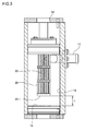
Fig. 1 is a perspective view illustrating an ion-exchange equipment according to an embodiment of the present invention; -
Fig. 2 is a sectional view taken along the line II-II inFig. 1 ; -
Fig. 3 is a sectional view taken along the line III-III inFig. 1 ; -
Fig. 4 is a graph representing a relationship between filling amount of the ion-exchange resin and pressure loss of the ion-exchange equipment according to the embodiment of the present invention; and -
Fig. 5 is a graph representing a relationship between ion exchanging efficiency and breakthrough ratio of the ion-exchange equipment according to the embodiment of the present invention. - A preferred embodiment for carrying out the present invention will be described hereunder with reference to the accompanying drawings. It is to be noted that the described embodiment is not limited to the present invention recited in appended claims and combinations of characteristics of the embodiment described in the present specification is not essential to solve problems and/or object of the present invention, and it is also to be noted that terms such as "upper", "lower", "right", "left" and others indicating direction or like are used herein basically with reference to the illustration of the drawings.
- With reference to
Fig. 1 , an ion-exchange equipment 1 according to one embodiment of the present invention is provided with atank unit 10 having a flow-in port (supply port) connected to a cooling circuit for introducing cooling liquid inside thetank 10 and a flow-out port (discharge port) also connected to the cooling circuit for discharging the cooling liquid to the cooling circuit. - The
tank unit 10 is formed with a circular through hole in a perpendicular direction thereof, and the circular through hole has both ends closed bylid members exchange chamber 13 extending in the axial direction of thetank unit 10 and having a circular cross section taken perpendicularly to the axial direction of the ion-exchange chamber. - The ion-
exchange chamber 13 is filled up with ion-exchange resin composed of a number of particles, not shown, at filling rate of approximately 80% or less with respect to entire inner volume of the ion-exchange chamber 13. If such ion filling rate exceeds 80%, it becomes difficult to ensure a sufficient space for revolving and dispersing the ion-exchange resin inside the ion-exchange chamber, which will be explained hereinafter, which results in causing of high pressure loss. Thus, herein, the upper limit of the resin filling rate is set to approximately 80%. - Further, the reason why the upper limit of the resin filling rate is limited to 80% is based on an event such that, with reference to the graph of
Fig. 4 , when the ion-exchange resin filling amount in the ion-exchange chamber having inner volume of 900ml is changed in the ion-exchanging rate, the ion-exchange resin amount exceeds an inner volume of 800ml of the ion-exchange chamber, the pressure loss rapidly increases. Because of this matter, the ion-exchange resin filling rate is set to be not more than 88.8%, and preferably, approximately, not more than 80% in the present embodiment. - The flow-out
port 12 is formed to thelid member 12 mounted to an upper end of thetank unit 10, and in the ion-exchange chamber 13, acylindrical member 20 is located so as to extend directly downward toward abottom surface 14 of the ion-exchange chamber 13. - The
cylindrical member 20 is a tubular hollow cylindrical member capable of passing the cooling liquid therein, and a plurality ofholes 21 are formed to a peripheral wall surface thereof and amesh member 23 is provided so as to cover theseholes 21, and themesh member 23 is also formed with a plurality of holes each having a diameter smaller than that of the ion-exchange resin filling the ion-exchange chamber to thereby prevent the ion-exchange resin from leaking outward through the flow-out port (discharge port) 12. Further, since thismesh member 23 is made of stainless steel, the mesh member has a high strength to thereby effectively prevent themesh member 23 from being damaged itself. - As shown in
Fig. 3 , thecylindrical member 20 is disposed in a manner that a lower (bottom) end 22a of thecylindrical member 20 is opposed to thebottom surface 14 of the ion-exchange chamber 13 so as to take a predetermined distance L between thelower end 22 of thecylindrical member 20 to thebottom surface 14 of the ion-exchange chamber 23. Although this distance L may be optionally changed in accordance with a required pressure loss and ion-exchange rate, the pressure loss can be reduced by setting this distance to be small. However, if thelower end 22 abuts against thebottom surface 23, the ion-exchange resin will clog, and it is necessary to set the distance L so as not to cause such clogging. - Furthermore, since the
cylindrical member 20 is provides so as to extend axially with a predetermined clearance, a large surface area can be ensured, and hence, the pressure loss at a time when the cooling liquid passes through theholes 21 formed in the peripheral wall surface of thecylindrical member 20 can be effectively reduced. - In the meantime, as shown in
Fig. 2 , the flow-inport 11 is formed so as to extend tangentially to the ion-exchange chamber 13, and as also shown inFig. 3 , the flow-inport 11 is arranged on the upper end side of the ion-exchange chamber 13. According to such arrangement of the flow-inport 11, the cooling liquid introduced through the flow-inport 11 forms a current of flow toward the flow-outport 12 while spirally turning along the inner wall surface of theion exchange chamber 13 by flow-in power of the introduced cooling liquid through the flow-inport 11. - The ion-exchange resin filling the ion-
exchange chamber 13 is packed with filling rate of not more than approximately 80% of the inner volume of the ion-exchange chamber 13, and accordingly, the ion-exchange resin is agitated by the spiral flow of the cooling liquid, as mentioned above, so that the ion-exchange resin can uniformly contact the cooling liquid and can be evenly used, thus improving the ion exchanging efficiency, and hence, effectively remove the impurity ion. - Furthermore, since the ion-exchange resin is dispersed by being agitated along the cooling liquid flow, the clearance between the particles constituting the ion-exchange resin can be sufficiently ensured and the cooling liquid can thus easily flow, thereby suppressing the pressure loss of the ion-exchange resin to be low.
-
Fig. 5 is a graph representing an ion-exchange rate and a breakthrough rate between an example of the ion-exchange equipment 1 according to the embodiment of the present invention and a comparative example having a structure in which a conventional ion-exchange resin fills under pressure. - As is apparent from the graph of
Fig. 5 , in the example of the present invention, the ion-exchange resin could maintain the initial function and efficiency till the ion-exchange resin was broken through and the ion-exchange reaction proceeded till the breakthrough rate reached 100%. - On the other hand, in the comparative example, the ion-exchange resin could not maintain the initial efficiency till the ion-exchange resin was broken through and the efficiency of the ion-exchange reaction reduced before the breakthrough rate reached 100%. From this fact, it is found that the ion-exchange resin in the example of the present invention can efficiently remove the impurity in comparison with reference to the graph of
Fig. 5 . - It is further to be noted that the present invention is not limited to the embodiment described above and many other changes and modifications or alternations may be made without departing from the scope of the appended claims.
- For example, as described above, with the ion-
exchange equipment 1 according to the present embodiment, although the description was made as the case in which the flow-inport 11 is provided on the upper end side of the ion-exchange chamber 13, the arranged position of the flow-inport 11 is not limited to such position as described above, and it may be possible to arrange the flow-in port as far as the flow-in port is provided in the direction tangential to theion exchange chamber 13. - Furthermore, in the described embodiment, although the flow-out
port 12 is provided to the upper end surface of thetank unit 10, the flow-out port may be provided to any other portion of thetank unit 10 as far as the cooling liquid can flow out, and thecylindrical member 20 disposed in the ion-exchange chamber 13 may not be provided - Still furthermore, although the described embodiment provides the flow-out
port 12 formed to the upper end surface of thetank unit 10, the flow-outport 12 may be provided to any portion of the tank unit as far as the cooling liquid can flow out, and thecylindrical member 20 disposed in the ion-exchange chamber 13 may not be provided. Furthermore, themesh 23 covering thehole 21 may be formed of a synthetic resin, for example, in spite of the steel as mentioned above.
Claims (6)
- An ion-exchange equipment comprising:a tank unit formed with a cooling liquid flow-in port and a cooling liquid flow-out port and provided therein with an ion-exchange chamber; andan ion-exchange resin in form of particles filling the ion-exchange chamber of the tank unit,wherein the ion-exchange chamber is provided so as to extend along an axial direction of the tank unit and the ion-exchange chamber has a circular cross section taken perpendicularly to the axial direction of the tank unit, and the cooling liquid flow-in port is formed so as to extend in a tangential direction of the ion-exchange chamber.
- The ion-exchange equipment according to claim 1, wherein the cooling liquid flow-out port is formed to one end portion of the ion-exchange chamber and the tank unit is provided with a cylindrical member extending from the cooling liquid flow-out port toward a bottom surface of the ion-exchange chamber.
- The ion-exchange equipment according to claim 2, wherein the cylindrical member is formed, in a peripheral wall section thereof, with a plurality of holes each having a diameter smaller than that of each particle of the ion-exchange resin.
- The ion-exchange equipment according to claim 2, wherein the cylindrical member is disposed in the ion-exchange chamber so as to face the bottom surface of the ion-exchange chamber with a predetermined distance therebetween.
- The ion-exchange equipment according to claim 1, wherein the cooling liquid flow-in port is disposed on an upper end side of the ion-exchange chamber.
- The ion-exchange equipment according to claim 1, wherein the ion-exchange resin fills an interior of the ion-exchange chamber at a filling rate of not more than 80% of an inner volume of the ion-exchange chamber.
Applications Claiming Priority (1)
| Application Number | Priority Date | Filing Date | Title |
|---|---|---|---|
| JP2013259218A JP6257301B2 (en) | 2013-12-16 | 2013-12-16 | Ion exchanger |
Publications (2)
| Publication Number | Publication Date |
|---|---|
| EP2883843A1 true EP2883843A1 (en) | 2015-06-17 |
| EP2883843B1 EP2883843B1 (en) | 2018-04-04 |
Family
ID=52432619
Family Applications (1)
| Application Number | Title | Priority Date | Filing Date |
|---|---|---|---|
| EP14196004.7A Not-in-force EP2883843B1 (en) | 2013-12-16 | 2014-12-03 | Ion-exchangeer for fuel cell |
Country Status (3)
| Country | Link |
|---|---|
| US (1) | US9614234B2 (en) |
| EP (1) | EP2883843B1 (en) |
| JP (1) | JP6257301B2 (en) |
Families Citing this family (4)
| Publication number | Priority date | Publication date | Assignee | Title |
|---|---|---|---|---|
| WO2016139838A1 (en) * | 2015-03-05 | 2016-09-09 | ブラザー工業株式会社 | Gas-liquid separator for fuel cell system |
| US10167206B2 (en) | 2015-07-23 | 2019-01-01 | Ecolab Usa Inc. | Method and apparatus for recharging a deionization vessel |
| JP6648092B2 (en) * | 2017-11-15 | 2020-02-14 | 住友化学株式会社 | Acid gas separation membrane sheet and method for producing the same |
| CN117599861B (en) * | 2023-12-22 | 2024-04-26 | 山东兆光色谱分离技术有限公司 | Ion exchange column and ion exchange system |
Citations (6)
| Publication number | Priority date | Publication date | Assignee | Title |
|---|---|---|---|---|
| JPH08164386A (en) | 1994-12-14 | 1996-06-25 | Matsushita Electric Ind Co Ltd | Water softening device |
| JP2005071709A (en) * | 2003-08-21 | 2005-03-17 | Toyo Roki Mfg Co Ltd | Ion removing filter for fuel cell |
| US20070108056A1 (en) * | 2005-10-06 | 2007-05-17 | Pionetics Corporation | Electrochemical ion exchange treatment of fluids |
| FR2900000A1 (en) * | 2006-04-14 | 2007-10-19 | Renault Sas | Power module for motor vehicle, has stream splitter providing fluid supplied to degassing vase and containing reformate and large proportion of water droplets, and providing another fluid containing reformate and supplied to fuel cell |
| US20070264554A1 (en) * | 2004-09-06 | 2007-11-15 | Toyota Jidosha Kabushiki Kaisha | Fuel Cell System |
| WO2013054758A1 (en) * | 2011-10-14 | 2013-04-18 | 日産自動車株式会社 | Ion exchanger and cooling device equipped with ion exchanger |
Family Cites Families (7)
| Publication number | Priority date | Publication date | Assignee | Title |
|---|---|---|---|---|
| US2874847A (en) * | 1955-08-11 | 1959-02-24 | Whirlpool Co | Ion exchange device and method |
| US3586294A (en) * | 1969-02-20 | 1971-06-22 | James J Strong | Method and apparatus for creating a suspension of fine particles in a liquid |
| DE2147570A1 (en) * | 1971-09-23 | 1973-03-29 | Permutit Ag | Revolving ion exchange bed - with liquid flowing spirally inwards |
| JP4102744B2 (en) * | 2003-11-28 | 2008-06-18 | 東洋▲ろ▼機製造株式会社 | Ion exchange filter |
| JP4574464B2 (en) * | 2005-06-16 | 2010-11-04 | トヨタ紡織株式会社 | Ion remover |
| JP2010205661A (en) * | 2009-03-05 | 2010-09-16 | Toyota Boshoku Corp | Ion exchanger |
| JP5582071B2 (en) * | 2011-03-08 | 2014-09-03 | トヨタ紡織株式会社 | Ion exchanger |
-
2013
- 2013-12-16 JP JP2013259218A patent/JP6257301B2/en active Active
-
2014
- 2014-12-03 EP EP14196004.7A patent/EP2883843B1/en not_active Not-in-force
- 2014-12-08 US US14/562,866 patent/US9614234B2/en active Active
Patent Citations (6)
| Publication number | Priority date | Publication date | Assignee | Title |
|---|---|---|---|---|
| JPH08164386A (en) | 1994-12-14 | 1996-06-25 | Matsushita Electric Ind Co Ltd | Water softening device |
| JP2005071709A (en) * | 2003-08-21 | 2005-03-17 | Toyo Roki Mfg Co Ltd | Ion removing filter for fuel cell |
| US20070264554A1 (en) * | 2004-09-06 | 2007-11-15 | Toyota Jidosha Kabushiki Kaisha | Fuel Cell System |
| US20070108056A1 (en) * | 2005-10-06 | 2007-05-17 | Pionetics Corporation | Electrochemical ion exchange treatment of fluids |
| FR2900000A1 (en) * | 2006-04-14 | 2007-10-19 | Renault Sas | Power module for motor vehicle, has stream splitter providing fluid supplied to degassing vase and containing reformate and large proportion of water droplets, and providing another fluid containing reformate and supplied to fuel cell |
| WO2013054758A1 (en) * | 2011-10-14 | 2013-04-18 | 日産自動車株式会社 | Ion exchanger and cooling device equipped with ion exchanger |
Also Published As
| Publication number | Publication date |
|---|---|
| EP2883843B1 (en) | 2018-04-04 |
| JP6257301B2 (en) | 2018-01-10 |
| US9614234B2 (en) | 2017-04-04 |
| US20150171440A1 (en) | 2015-06-18 |
| JP2015112592A (en) | 2015-06-22 |
Similar Documents
| Publication | Publication Date | Title |
|---|---|---|
| EP2883843B1 (en) | Ion-exchangeer for fuel cell | |
| US7261816B2 (en) | Ion-exchange filter | |
| US10008754B2 (en) | Metal-air battery | |
| US7947171B2 (en) | Cooling device for fuel cell | |
| JP5860472B2 (en) | Ion exchanger and cooling device provided with ion exchanger | |
| EP2608303B1 (en) | Silencer for reducing acoustic noise of fuel cell system | |
| US20160089618A1 (en) | Ion-exchanger | |
| KR101272593B1 (en) | De-Mineralizer for fuel cell | |
| US20170187050A1 (en) | Fuel cell unit including an exchangeable deionization device and a vehicle including such a fuel cell unit | |
| CN109962264B (en) | Built-in deionization system of water tank of fuel cell | |
| JP2016198757A (en) | Three-phase separator having high thermal efficiency | |
| JP5582071B2 (en) | Ion exchanger | |
| JP2014096353A (en) | Cooler for fuel cell | |
| CN114653099B (en) | Oil purifying device | |
| KR20080056488A (en) | The surge lines to reduce heat loss of the pressurizer in an integral reactor | |
| KR101472425B1 (en) | Electrolytic recycling unit and electrolytic recycling device with the same | |
| US10718576B2 (en) | Ion exchanger | |
| JP7486212B2 (en) | Means and methods for degassing liquids | |
| EP3056266B1 (en) | Mass transfer apparatus | |
| CN110921791B (en) | In-situ electrode regeneration device and method | |
| JP7256464B2 (en) | Cooling system | |
| EP1961483B1 (en) | Ion exchange reactor | |
| JP2007059294A (en) | Fuel cell system | |
| JP5262839B2 (en) | Fuel cell cooling system | |
| JP2022540325A (en) | Liquid degassing means and method |
Legal Events
| Date | Code | Title | Description |
|---|---|---|---|
| PUAI | Public reference made under article 153(3) epc to a published international application that has entered the european phase |
Free format text: ORIGINAL CODE: 0009012 |
|
| 17P | Request for examination filed |
Effective date: 20141203 |
|
| AK | Designated contracting states |
Kind code of ref document: A1 Designated state(s): AL AT BE BG CH CY CZ DE DK EE ES FI FR GB GR HR HU IE IS IT LI LT LU LV MC MK MT NL NO PL PT RO RS SE SI SK SM TR |
|
| AX | Request for extension of the european patent |
Extension state: BA ME |
|
| R17P | Request for examination filed (corrected) |
Effective date: 20151216 |
|
| RBV | Designated contracting states (corrected) |
Designated state(s): AL AT BE BG CH CY CZ DE DK EE ES FI FR GB GR HR HU IE IS IT LI LT LU LV MC MK MT NL NO PL PT RO RS SE SI SK SM TR |
|
| 17Q | First examination report despatched |
Effective date: 20161130 |
|
| RIC1 | Information provided on ipc code assigned before grant |
Ipc: B01J 47/022 20170101ALI20170914BHEP Ipc: B01J 47/10 20170101ALI20170914BHEP Ipc: C02F 103/02 20060101ALN20170914BHEP Ipc: H01M 8/04044 20160101ALI20170914BHEP Ipc: B01D 15/18 20060101ALI20170914BHEP Ipc: C02F 1/42 20060101AFI20170914BHEP |
|
| GRAP | Despatch of communication of intention to grant a patent |
Free format text: ORIGINAL CODE: EPIDOSNIGR1 |
|
| INTG | Intention to grant announced |
Effective date: 20171026 |
|
| GRAS | Grant fee paid |
Free format text: ORIGINAL CODE: EPIDOSNIGR3 |
|
| GRAA | (expected) grant |
Free format text: ORIGINAL CODE: 0009210 |
|
| AK | Designated contracting states |
Kind code of ref document: B1 Designated state(s): AL AT BE BG CH CY CZ DE DK EE ES FI FR GB GR HR HU IE IS IT LI LT LU LV MC MK MT NL NO PL PT RO RS SE SI SK SM TR |
|
| REG | Reference to a national code |
Ref country code: GB Ref legal event code: FG4D |
|
| REG | Reference to a national code |
Ref country code: CH Ref legal event code: EP |
|
| REG | Reference to a national code |
Ref country code: AT Ref legal event code: REF Ref document number: 985414 Country of ref document: AT Kind code of ref document: T Effective date: 20180415 |
|
| REG | Reference to a national code |
Ref country code: IE Ref legal event code: FG4D |
|
| REG | Reference to a national code |
Ref country code: DE Ref legal event code: R096 Ref document number: 602014023246 Country of ref document: DE |
|
| REG | Reference to a national code |
Ref country code: NL Ref legal event code: MP Effective date: 20180404 |
|
| REG | Reference to a national code |
Ref country code: LT Ref legal event code: MG4D |
|
| PG25 | Lapsed in a contracting state [announced via postgrant information from national office to epo] |
Ref country code: NL Free format text: LAPSE BECAUSE OF FAILURE TO SUBMIT A TRANSLATION OF THE DESCRIPTION OR TO PAY THE FEE WITHIN THE PRESCRIBED TIME-LIMIT Effective date: 20180404 |
|
| PG25 | Lapsed in a contracting state [announced via postgrant information from national office to epo] |
Ref country code: ES Free format text: LAPSE BECAUSE OF FAILURE TO SUBMIT A TRANSLATION OF THE DESCRIPTION OR TO PAY THE FEE WITHIN THE PRESCRIBED TIME-LIMIT Effective date: 20180404 Ref country code: AL Free format text: LAPSE BECAUSE OF FAILURE TO SUBMIT A TRANSLATION OF THE DESCRIPTION OR TO PAY THE FEE WITHIN THE PRESCRIBED TIME-LIMIT Effective date: 20180404 Ref country code: BG Free format text: LAPSE BECAUSE OF FAILURE TO SUBMIT A TRANSLATION OF THE DESCRIPTION OR TO PAY THE FEE WITHIN THE PRESCRIBED TIME-LIMIT Effective date: 20180704 Ref country code: LT Free format text: LAPSE BECAUSE OF FAILURE TO SUBMIT A TRANSLATION OF THE DESCRIPTION OR TO PAY THE FEE WITHIN THE PRESCRIBED TIME-LIMIT Effective date: 20180404 Ref country code: NO Free format text: LAPSE BECAUSE OF FAILURE TO SUBMIT A TRANSLATION OF THE DESCRIPTION OR TO PAY THE FEE WITHIN THE PRESCRIBED TIME-LIMIT Effective date: 20180704 Ref country code: FI Free format text: LAPSE BECAUSE OF FAILURE TO SUBMIT A TRANSLATION OF THE DESCRIPTION OR TO PAY THE FEE WITHIN THE PRESCRIBED TIME-LIMIT Effective date: 20180404 Ref country code: SE Free format text: LAPSE BECAUSE OF FAILURE TO SUBMIT A TRANSLATION OF THE DESCRIPTION OR TO PAY THE FEE WITHIN THE PRESCRIBED TIME-LIMIT Effective date: 20180404 Ref country code: PL Free format text: LAPSE BECAUSE OF FAILURE TO SUBMIT A TRANSLATION OF THE DESCRIPTION OR TO PAY THE FEE WITHIN THE PRESCRIBED TIME-LIMIT Effective date: 20180404 |
|
| PG25 | Lapsed in a contracting state [announced via postgrant information from national office to epo] |
Ref country code: LV Free format text: LAPSE BECAUSE OF FAILURE TO SUBMIT A TRANSLATION OF THE DESCRIPTION OR TO PAY THE FEE WITHIN THE PRESCRIBED TIME-LIMIT Effective date: 20180404 Ref country code: GR Free format text: LAPSE BECAUSE OF FAILURE TO SUBMIT A TRANSLATION OF THE DESCRIPTION OR TO PAY THE FEE WITHIN THE PRESCRIBED TIME-LIMIT Effective date: 20180705 Ref country code: HR Free format text: LAPSE BECAUSE OF FAILURE TO SUBMIT A TRANSLATION OF THE DESCRIPTION OR TO PAY THE FEE WITHIN THE PRESCRIBED TIME-LIMIT Effective date: 20180404 Ref country code: RS Free format text: LAPSE BECAUSE OF FAILURE TO SUBMIT A TRANSLATION OF THE DESCRIPTION OR TO PAY THE FEE WITHIN THE PRESCRIBED TIME-LIMIT Effective date: 20180404 |
|
| REG | Reference to a national code |
Ref country code: AT Ref legal event code: MK05 Ref document number: 985414 Country of ref document: AT Kind code of ref document: T Effective date: 20180404 |
|
| PG25 | Lapsed in a contracting state [announced via postgrant information from national office to epo] |
Ref country code: PT Free format text: LAPSE BECAUSE OF FAILURE TO SUBMIT A TRANSLATION OF THE DESCRIPTION OR TO PAY THE FEE WITHIN THE PRESCRIBED TIME-LIMIT Effective date: 20180806 |
|
| REG | Reference to a national code |
Ref country code: DE Ref legal event code: R097 Ref document number: 602014023246 Country of ref document: DE |
|
| PG25 | Lapsed in a contracting state [announced via postgrant information from national office to epo] |
Ref country code: RO Free format text: LAPSE BECAUSE OF FAILURE TO SUBMIT A TRANSLATION OF THE DESCRIPTION OR TO PAY THE FEE WITHIN THE PRESCRIBED TIME-LIMIT Effective date: 20180404 Ref country code: SK Free format text: LAPSE BECAUSE OF FAILURE TO SUBMIT A TRANSLATION OF THE DESCRIPTION OR TO PAY THE FEE WITHIN THE PRESCRIBED TIME-LIMIT Effective date: 20180404 Ref country code: CZ Free format text: LAPSE BECAUSE OF FAILURE TO SUBMIT A TRANSLATION OF THE DESCRIPTION OR TO PAY THE FEE WITHIN THE PRESCRIBED TIME-LIMIT Effective date: 20180404 Ref country code: DK Free format text: LAPSE BECAUSE OF FAILURE TO SUBMIT A TRANSLATION OF THE DESCRIPTION OR TO PAY THE FEE WITHIN THE PRESCRIBED TIME-LIMIT Effective date: 20180404 Ref country code: EE Free format text: LAPSE BECAUSE OF FAILURE TO SUBMIT A TRANSLATION OF THE DESCRIPTION OR TO PAY THE FEE WITHIN THE PRESCRIBED TIME-LIMIT Effective date: 20180404 Ref country code: AT Free format text: LAPSE BECAUSE OF FAILURE TO SUBMIT A TRANSLATION OF THE DESCRIPTION OR TO PAY THE FEE WITHIN THE PRESCRIBED TIME-LIMIT Effective date: 20180404 |
|
| PLBE | No opposition filed within time limit |
Free format text: ORIGINAL CODE: 0009261 |
|
| STAA | Information on the status of an ep patent application or granted ep patent |
Free format text: STATUS: NO OPPOSITION FILED WITHIN TIME LIMIT |
|
| PG25 | Lapsed in a contracting state [announced via postgrant information from national office to epo] |
Ref country code: IT Free format text: LAPSE BECAUSE OF FAILURE TO SUBMIT A TRANSLATION OF THE DESCRIPTION OR TO PAY THE FEE WITHIN THE PRESCRIBED TIME-LIMIT Effective date: 20180404 Ref country code: SM Free format text: LAPSE BECAUSE OF FAILURE TO SUBMIT A TRANSLATION OF THE DESCRIPTION OR TO PAY THE FEE WITHIN THE PRESCRIBED TIME-LIMIT Effective date: 20180404 |
|
| 26N | No opposition filed |
Effective date: 20190107 |
|
| PG25 | Lapsed in a contracting state [announced via postgrant information from national office to epo] |
Ref country code: SI Free format text: LAPSE BECAUSE OF FAILURE TO SUBMIT A TRANSLATION OF THE DESCRIPTION OR TO PAY THE FEE WITHIN THE PRESCRIBED TIME-LIMIT Effective date: 20180404 |
|
| REG | Reference to a national code |
Ref country code: CH Ref legal event code: PL |
|
| PG25 | Lapsed in a contracting state [announced via postgrant information from national office to epo] |
Ref country code: MC Free format text: LAPSE BECAUSE OF FAILURE TO SUBMIT A TRANSLATION OF THE DESCRIPTION OR TO PAY THE FEE WITHIN THE PRESCRIBED TIME-LIMIT Effective date: 20180404 Ref country code: LU Free format text: LAPSE BECAUSE OF NON-PAYMENT OF DUE FEES Effective date: 20181203 |
|
| REG | Reference to a national code |
Ref country code: IE Ref legal event code: MM4A |
|
| REG | Reference to a national code |
Ref country code: BE Ref legal event code: MM Effective date: 20181231 |
|
| PG25 | Lapsed in a contracting state [announced via postgrant information from national office to epo] |
Ref country code: IE Free format text: LAPSE BECAUSE OF NON-PAYMENT OF DUE FEES Effective date: 20181203 |
|
| PG25 | Lapsed in a contracting state [announced via postgrant information from national office to epo] |
Ref country code: BE Free format text: LAPSE BECAUSE OF NON-PAYMENT OF DUE FEES Effective date: 20181231 |
|
| PG25 | Lapsed in a contracting state [announced via postgrant information from national office to epo] |
Ref country code: LI Free format text: LAPSE BECAUSE OF NON-PAYMENT OF DUE FEES Effective date: 20181231 Ref country code: CH Free format text: LAPSE BECAUSE OF NON-PAYMENT OF DUE FEES Effective date: 20181231 |
|
| PG25 | Lapsed in a contracting state [announced via postgrant information from national office to epo] |
Ref country code: MT Free format text: LAPSE BECAUSE OF NON-PAYMENT OF DUE FEES Effective date: 20181203 |
|
| PGFP | Annual fee paid to national office [announced via postgrant information from national office to epo] |
Ref country code: DE Payment date: 20191210 Year of fee payment: 6 |
|
| PGFP | Annual fee paid to national office [announced via postgrant information from national office to epo] |
Ref country code: FR Payment date: 20191220 Year of fee payment: 6 |
|
| PG25 | Lapsed in a contracting state [announced via postgrant information from national office to epo] |
Ref country code: TR Free format text: LAPSE BECAUSE OF FAILURE TO SUBMIT A TRANSLATION OF THE DESCRIPTION OR TO PAY THE FEE WITHIN THE PRESCRIBED TIME-LIMIT Effective date: 20180404 |
|
| PGFP | Annual fee paid to national office [announced via postgrant information from national office to epo] |
Ref country code: GB Payment date: 20191220 Year of fee payment: 6 |
|
| PG25 | Lapsed in a contracting state [announced via postgrant information from national office to epo] |
Ref country code: HU Free format text: LAPSE BECAUSE OF FAILURE TO SUBMIT A TRANSLATION OF THE DESCRIPTION OR TO PAY THE FEE WITHIN THE PRESCRIBED TIME-LIMIT; INVALID AB INITIO Effective date: 20141203 Ref country code: MK Free format text: LAPSE BECAUSE OF NON-PAYMENT OF DUE FEES Effective date: 20180404 Ref country code: CY Free format text: LAPSE BECAUSE OF FAILURE TO SUBMIT A TRANSLATION OF THE DESCRIPTION OR TO PAY THE FEE WITHIN THE PRESCRIBED TIME-LIMIT Effective date: 20180404 |
|
| PG25 | Lapsed in a contracting state [announced via postgrant information from national office to epo] |
Ref country code: IS Free format text: LAPSE BECAUSE OF FAILURE TO SUBMIT A TRANSLATION OF THE DESCRIPTION OR TO PAY THE FEE WITHIN THE PRESCRIBED TIME-LIMIT Effective date: 20180804 |
|
| REG | Reference to a national code |
Ref country code: DE Ref legal event code: R119 Ref document number: 602014023246 Country of ref document: DE |
|
| GBPC | Gb: european patent ceased through non-payment of renewal fee |
Effective date: 20201203 |
|
| PG25 | Lapsed in a contracting state [announced via postgrant information from national office to epo] |
Ref country code: FR Free format text: LAPSE BECAUSE OF NON-PAYMENT OF DUE FEES Effective date: 20201231 |
|
| PG25 | Lapsed in a contracting state [announced via postgrant information from national office to epo] |
Ref country code: GB Free format text: LAPSE BECAUSE OF NON-PAYMENT OF DUE FEES Effective date: 20201203 Ref country code: DE Free format text: LAPSE BECAUSE OF NON-PAYMENT OF DUE FEES Effective date: 20210701 |