EP2883764A1 - Balai d'essuie-glace pour un système d'essuyage d'une vitre de véhicule et son procédé d'assemblage - Google Patents
Balai d'essuie-glace pour un système d'essuyage d'une vitre de véhicule et son procédé d'assemblage Download PDFInfo
- Publication number
- EP2883764A1 EP2883764A1 EP14197848.6A EP14197848A EP2883764A1 EP 2883764 A1 EP2883764 A1 EP 2883764A1 EP 14197848 A EP14197848 A EP 14197848A EP 2883764 A1 EP2883764 A1 EP 2883764A1
- Authority
- EP
- European Patent Office
- Prior art keywords
- longitudinal
- blade
- wiper
- housing
- brush
- Prior art date
- Legal status (The legal status is an assumption and is not a legal conclusion. Google has not performed a legal analysis and makes no representation as to the accuracy of the status listed.)
- Granted
Links
- 238000000034 method Methods 0.000 title claims description 6
- 239000012530 fluid Substances 0.000 claims description 4
- 239000011324 bead Substances 0.000 claims description 2
- 238000010438 heat treatment Methods 0.000 claims description 2
- 239000007788 liquid Substances 0.000 claims description 2
- 238000005406 washing Methods 0.000 claims description 2
- 208000031968 Cadaver Diseases 0.000 description 7
- 244000007853 Sarothamnus scoparius Species 0.000 description 5
- 238000005516 engineering process Methods 0.000 description 2
- 238000007747 plating Methods 0.000 description 2
- 230000002441 reversible effect Effects 0.000 description 2
- XLYOFNOQVPJJNP-UHFFFAOYSA-N water Substances O XLYOFNOQVPJJNP-UHFFFAOYSA-N 0.000 description 2
- 241001631457 Cannula Species 0.000 description 1
- 240000008042 Zea mays Species 0.000 description 1
- 238000004891 communication Methods 0.000 description 1
- 230000000295 complement effect Effects 0.000 description 1
- 238000013016 damping Methods 0.000 description 1
- 230000005489 elastic deformation Effects 0.000 description 1
- 239000003607 modifier Substances 0.000 description 1
Images

Classifications
-
- B—PERFORMING OPERATIONS; TRANSPORTING
- B60—VEHICLES IN GENERAL
- B60S—SERVICING, CLEANING, REPAIRING, SUPPORTING, LIFTING, OR MANOEUVRING OF VEHICLES, NOT OTHERWISE PROVIDED FOR
- B60S1/00—Cleaning of vehicles
- B60S1/02—Cleaning windscreens, windows or optical devices
- B60S1/04—Wipers or the like, e.g. scrapers
- B60S1/32—Wipers or the like, e.g. scrapers characterised by constructional features of wiper blade arms or blades
- B60S1/38—Wiper blades
- B60S1/3806—Means, or measures taken, for influencing the aerodynamic quality of the wiper blades
- B60S1/381—Spoilers mounted on the squeegee or on the vertebra
-
- B—PERFORMING OPERATIONS; TRANSPORTING
- B60—VEHICLES IN GENERAL
- B60S—SERVICING, CLEANING, REPAIRING, SUPPORTING, LIFTING, OR MANOEUVRING OF VEHICLES, NOT OTHERWISE PROVIDED FOR
- B60S1/00—Cleaning of vehicles
- B60S1/02—Cleaning windscreens, windows or optical devices
- B60S1/04—Wipers or the like, e.g. scrapers
- B60S1/32—Wipers or the like, e.g. scrapers characterised by constructional features of wiper blade arms or blades
- B60S1/38—Wiper blades
- B60S1/3848—Flat-type wiper blade, i.e. without harness
- B60S1/3874—Flat-type wiper blade, i.e. without harness with a reinforcing vertebra
- B60S1/3875—Flat-type wiper blade, i.e. without harness with a reinforcing vertebra rectangular section
- B60S1/3881—Flat-type wiper blade, i.e. without harness with a reinforcing vertebra rectangular section in additional element, e.g. spoiler
-
- B—PERFORMING OPERATIONS; TRANSPORTING
- B60—VEHICLES IN GENERAL
- B60S—SERVICING, CLEANING, REPAIRING, SUPPORTING, LIFTING, OR MANOEUVRING OF VEHICLES, NOT OTHERWISE PROVIDED FOR
- B60S1/00—Cleaning of vehicles
- B60S1/02—Cleaning windscreens, windows or optical devices
- B60S1/04—Wipers or the like, e.g. scrapers
- B60S1/32—Wipers or the like, e.g. scrapers characterised by constructional features of wiper blade arms or blades
- B60S1/38—Wiper blades
- B60S1/3803—Wiper blades heated wiper blades
- B60S1/3805—Wiper blades heated wiper blades electrically
-
- B—PERFORMING OPERATIONS; TRANSPORTING
- B60—VEHICLES IN GENERAL
- B60S—SERVICING, CLEANING, REPAIRING, SUPPORTING, LIFTING, OR MANOEUVRING OF VEHICLES, NOT OTHERWISE PROVIDED FOR
- B60S1/00—Cleaning of vehicles
- B60S1/02—Cleaning windscreens, windows or optical devices
- B60S1/46—Cleaning windscreens, windows or optical devices using liquid; Windscreen washers
- B60S1/48—Liquid supply therefor
- B60S1/52—Arrangement of nozzles; Liquid spreading means
- B60S1/522—Arrangement of nozzles; Liquid spreading means moving liquid spreading means, e.g. arranged in wiper arms
- B60S1/524—Arrangement of nozzles; Liquid spreading means moving liquid spreading means, e.g. arranged in wiper arms arranged in wiper blades
Definitions
- the present invention relates to a wiper blade for a wiper system of a vehicle window, in particular an automobile, a wiper system of a vehicle window, and a method of assembling a vehicle window. a vehicle wiper blade.
- a wiper blade for a wiper system of a motor vehicle window includes a longitudinal body carrying a wiper blade, generally made of rubber, intended to rub against the windshield of the vehicle to evacuate. water by bringing it out of the driver's field of vision.
- the wiper further comprises at least one elongate strip-shaped elastic support member, also called stiffening vertebra, which optionally imparts a bend to the wiper blade, so as to promote the application of this blade on the windshield.
- Some wiper blades are equipped with a blade holding member to which is attached a carrier body of an aerodynamic baffle for improving the aerodynamic performance of the blade and ensure its plating on the windshield.
- the holding member then generally comprises a first housing for receiving a heel of the blade and a second housing for receiving the stiffening vertebra.
- the body comprises fastening means to the holding member and said aerodynamic deflector.
- Such brushes are for example described in the applications EP 2 415 645A1 , DE 10 2011 078185A1 and US 2011/016653A1 .
- the present invention provides a new broom technology, which is simple, effective and economical.
- the cavity of the longitudinal body may be configured to slidably receive said support member. It may have in section a substantially rectangular shape. It may have dimensions substantially equal to those of said support member, ready assembly games. It may have a width and / or a height substantially equal to the width, respectively to the thickness of said strip-shaped support member, to the ready assembly sets. These sets are for example less than 1 mm, or even less than 0.5 mm.
- the longitudinal body may include a portion defining said cavity.
- This part is preferably a lower part of the body longitudinal. This part can thus extend below the baffle of the body, which generally forms the upper part of the longitudinal body.
- the longitudinal holding member may comprise a housing, said first housing, for receiving a heel of the blade.
- the holding member may further comprise a housing, said second housing, for receiving said portion of the longitudinal body.
- the second housing of the member is here used to receive a portion of the longitudinal body and in particular the part the body defining the receiving cavity of said support member.
- the second housing of the holding member may be configured to receive by longitudinal sliding said portion of the longitudinal body. It may have dimensions substantially equal to those of said portion of the longitudinal body, ready assembly games. These sets are for example less than 1 mm, or even less than 0.5 mm.
- the fastening means of the longitudinal body to the holding member may be located above its portion defining said cavity.
- the fastening means of the longitudinal body may comprise lateral longitudinal grooves and / or lateral longitudinal flanges. These grooves and / or flanges may be substantially parallel to each other and perpendicular to a median longitudinal plane of the blade.
- Said support member may extend above the heel of the blade.
- the present invention further relates to a wiper system of a vehicle window, in particular an automobile, comprising at least one wiper according to any one of the above definitions.
- Step a) may be performed before step c) and allow forming a first module comprising the holding member carrying the blade whose heel is inserted into the first housing of the holding member. Independently of step a), step b) can thus make it possible to form a second module independent of the holding member.
- the particular technology of the brush according to the invention allows the assembly of two modules pre-assembled independently of one another, the first module comprising the holding member carrying the blade (whose heel is inserted into the first housing of the step-maintaining member a)), and the second module comprising the longitudinal body carrying the band-shaped elastic elongated support member (the latter being inserted into the cavity of the longitudinal body - step c).
- the first module comprising the holding member carrying the blade (whose heel is inserted into the first housing of the step-maintaining member a)
- the second module comprising the longitudinal body carrying the band-shaped elastic elongated support member (the latter being inserted into the cavity of the longitudinal body - step c).
- step c) is performed before step a).
- step b) is performed after step c).
- the longitudinal or lateral names refer to the orientation of the wiper blade according to the invention.
- the longitudinal direction corresponds to the main axis of the blade in which it extends
- the lateral orientations correspond to straight lines, that is to say which intersect the longitudinal direction, in particular perpendicular to the longitudinal axis of the blade in its plane of rotation.
- the external or internal denominations are assessed relative to the attachment point of the brush on the brush holder arm, the inner denomination corresponding to the part where the arm and a half-brush extend.
- the directions referenced as upper or lower correspond to orientations perpendicular to the plane of rotation of the wiper blade, the lower denomination containing the plane of the windshield.
- FIG 1 a system according to the prior art windshield wiper of a vehicle, in particular automobile.
- This system comprises a windscreen wiping brush 10 and a brush arm 12 which is partially shown and intended to be driven by a motor to follow a back-and-forth angular movement to evacuate the water. and possibly other undesirable elements covering the windshield.
- the brush 10 here comprises a longitudinal body 14, a wiper blade 16, generally made of rubber, and at least one support member 18 so as to promote the application of the blade 16 on the window of the vehicle.
- the longitudinal body 14 of the blade 10 comprises an upper fin 20 to improve the operation of the wiper system, the purpose of this fin 20 is to improve the broom plating on the windshield and therefore the aerodynamic performance of the system.
- the brush 10 further comprises hooks or hooking clips 22 of the blade 16 and the support member 18 on the longitudinal body 14, these clips 22 being located at each of the longitudinal ends of the body 14.
- the longitudinal body 14 of the brush is here made in two independent parts which are arranged substantially end to end and connected to one another by an intermediate connector 24.
- This connector 24 is interposed between the two parts of the longitudinal body 14 and comprises fastening means to these parts, such as cannulas.
- the blade 10 comprises an adapter 26 mounted on the connector 24 which allows an articulation of the blade 10 relative to the arm 12.
- the articulation of the blade 10 relative to the arm 12 is a hinge according to a rotational movement about an axis of rotation Y perpendicular to the longitudinal axis of the blade 10.
- the blade 10 must in fact have at least one degree of freedom in rotation relative to the arm 12, and more specifically with respect to a part terminal 28 of the arm 12, to allow the blade 10 to follow the curvature of the windshield.
- the invention relates to a particular type of wiper blade according to which the blade comprises a longitudinal member for holding the blade which carries the blade and on which is fixed the longitudinal body of the blade.
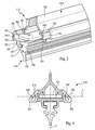
- the figures 2 and 3 represent a wiper blade 110 of this type according to the invention, the elements already described in the foregoing being designated in the following by the same reference numerals increased by a hundred.
- the references 114, 116, 118, 120 designate respectively the longitudinal body, the blade, the support member and the deflector of the blade 110.
- the holding member 130 of the brush 110 comprises a housing, said first housing or lower housing 132 for receiving a longitudinal bead 134 of the blade 116.
- the blade 116 is for example of the fir type, well known to the man of the job. Its upper end is connected by a hinge 136 and a damping member 138 to the heel 134. In known manner, in operation, the blade 116 can abut on the member 138 which dampens its reversal towards the front or towards the end. 'back.
- the housing 132 is configured to receive by longitudinal sliding the heel 134 of the blade 116.
- This housing 132 is delimited by a substantially horizontal wall 139 (here upper) and two side walls 140 substantially vertical which extend downwardly from the wall 139 and whose lower ends are each connected to a longitudinal flange 141.
- the flanges 141 are substantially coplanar and extend towards each other. They are substantially perpendicular to a median plane P of the brush which is a substantially vertical longitudinal plane passing substantially through the middle of the brush.
- the flanges 141 delimit between them a slot in which is slidable and is mounted a thinned lower portion of the heel 134 which here has a substantially T-shaped section.
- the holding member 130 comprises a housing, said second housing or upper housing 142 for receiving a lower portion 143 of the longitudinal body 114.
- the housing 142 is configured to receive by longitudinal sliding this portion 143 of the longitudinal body 114.
- This housing 142 is delimited by the wall 139 (here below) and two substantially vertical side walls 144 which extend upwardly from the wall 139 and whose upper ends are each connected to a longitudinal flange 145. These flanges 145 are substantially coplanar and extend towards one another.
- the longitudinal body 114 of the blade comprises an upper part defining the deflector 120 and the aforesaid lower portion 143 which is mounted in the housing 142 of the holding member 130.
- the lower portion 143 of the longitudinal body 114 has a generally parallelepipedal shape and comprises an internal cavity 146 for receiving the support element 118.
- the cavity 146 here has a shape in section substantially complementary to that of the support element 118.
- the cavity 146 is delimited by a substantially horizontal bottom wall 147 whose lateral longitudinal edges are connected to the lower ends of two substantially vertical longitudinal walls 148.
- the upper ends of these walls 148 are connected to longitudinal edges 149 which are substantially coplanar and substantially perpendicular to the plane P.
- These flanges 149 extend towards one another and define between them a slot which performs a communication between the cavity 146 and the remainder of the internal space of the longitudinal body 114.
- the upper portion of the longitudinal body 114 having the deflector 120 includes lateral longitudinal flanges 150 which are substantially coplanar and substantially perpendicular to the plane P. Each flange 150 extends in a direction opposite to the other flange. The flange 150 located at the front of the blade therefore extends forward, and the flange 150 located at the rear of the blade extends rearwardly.
- the flanges 150 extend above and away from the flanges 149, respectively, and together with the latter define lateral longitudinal grooves 151 for receiving the flanges 145 of the holding member 130, for fastening the longitudinal body 114 to the flange. holding member 130.
- the cavity 146 and the housings 132, 142 are configured to allow sliding of the support member 118, the heel 134 of the blade and the portion 143 of the longitudinal body 114, respectively.
- games in horizontal and vertical directions, exist between the support member 118 and the walls of the cavity, between the heel 134 and the walls of the housing 132 and between the body portion 143 longitudinal 114 and the housing 142.
- these games are not too important for the parts are wedged relative to each other in the mounting position.
- These sets are therefore preferably less than or equal to 1 mm, and more preferably less than or equal to 0.5 mm.
- the brush 110 has a symmetry with respect to the plane P.
- the brush 110 can be mounted as follows.
- the heel 134 of the blade 116 is mounted by longitudinal sliding in the housing 132 of the holding member 130 so as to form a first pre-assembled module.
- the support member 118 is slidably mounted in the cavity 146 of the longitudinal body 114 to form a second pre-assembled module. These modules are then assembled together.
- This assembly operation can be performed in two ways. For example, it is possible to position the modules end to end and to slide them into each other so that the portion 143 of the longitudinal body 114 slides in the housing 142 of the member 130.
- the figure 4 represents an alternative embodiment of the brush 210 according to the invention, which differs from the brush 110 described in the foregoing essentially in that it further comprises conduits 260 for fluid circulation, such as washing liquid ice.
- the brush 210 therefore comprises all the characteristics of the brush 110 described with reference to the figures 2 and 3 .
- the ducts 260 are located on the two lateral sides of the brush 210, respectively, and are cut by the same plane H perpendicular to the plane P and parallel to the support member 218.
- Each duct 260 is here delimited by a wall 244 (corresponding to the wall 144 of the body 130 of the figures 2 and 3 ) of the holding member 130 and a longitudinal wall 262 substantially curved section C.
- the lower and upper ends of the wall 244 are respectively connected to the lower and upper longitudinal edges of the wall 262 whose opening C is substantially oriented toward the support member 218.
Landscapes
- Engineering & Computer Science (AREA)
- Mechanical Engineering (AREA)
- Physics & Mathematics (AREA)
- Fluid Mechanics (AREA)
- Quality & Reliability (AREA)
- Cleaning In General (AREA)
- Automobile Manufacture Line, Endless Track Vehicle, Trailer (AREA)
- Vehicle Cleaning, Maintenance, Repair, Refitting, And Outriggers (AREA)
Abstract
Description
- La présente invention concerne un balai d'essuie-glace pour un système d'essuyage d'une vitre de véhicule, en particulier automobile, un système d'essuyage d'une vitre de véhicule, ainsi qu'un procédé d'assemblage d'un balai d'essuie-glace de véhicule.
- Typiquement, un balai d'essuie-glace pour un système d'essuyage d'une vitre de véhicule automobile comprend un corps longitudinal portant une lame d'essuyage, en général en caoutchouc, destinée à frotter contre le pare-brise du véhicule pour évacuer de l'eau en l'amenant en dehors du champ de vision du conducteur. Le balai comporte en outre au moins un élément de support allongé élastique en forme de bande, aussi appelé vertèbre de rigidification, qui confère éventuellement un cintrage à la lame d'essuyage, de manière à favoriser l'application de cette lame sur le parebrise.
- Certains balais d'essuie-glace sont équipés d'un organe de maintien de la lame auquel est fixé un corps porteur d'un déflecteur aérodynamique destiné à améliorer les performances aérodynamiques du balai et assurer son plaquage sur le pare brise. L'organe de maintien comprend alors en général un premier logement de réception d'un talon de la lame et un second logement de réception de la vertèbre de rigidification. Le corps comprend des moyens de fixation à l'organe de maintien et ledit déflecteur aérodynamique. De tels balais sont par exemple décrits dans les demandes
EP 2 415 645A1 ,DE 10 2011 078185A1 etUS 2011/016653A1 . - La présente invention propose une nouvelle technologie de balai, qui est simple, efficace et économique.
- L'invention propose à cet effet un balai d'essuie-glace pour un système d'essuyage d'une vitre de véhicule, en particulier automobile, comprenant :
- une lame d'essuyage,
- un élément de support allongé élastique en forme de bande,
- un organe longitudinal de maintien de la lame, et
- un corps longitudinal qui comprend un déflecteur aérodynamique et des moyens de fixation à l'organe de maintien,
- Le balai d'essuie-glace peut ainsi comprendre :
- un premier module comportant l'organe de maintien portant la lame d'essuyage,
assemblé à - un second module comportant le corps longitudinal qui comprend le déflecteur aérodynamique et les moyens de fixation à l'organe de maintien, et la cavité (146) de réception de l'élément de support allongé.
- La cavité du corps longitudinal peut être configurée pour recevoir par coulissement longitudinal ledit élément de support. Elle peut avoir en section une forme sensiblement rectangulaire. Elle peut avoir des dimensions sensiblement égales à celles dudit élément de support, aux jeux de montage prêts. Elle peut présenter une largeur et/ou une hauteur sensiblement égale à la largeur, respectivement à l'épaisseur dudit élément de support en forme de bande, aux jeux de montage prêts. Ces jeux sont par exemple inférieurs à 1 mm, voire inférieurs à 0,5 mm.
- Le corps longitudinal peut comprendre une partie définissant ladite cavité. Cette partie est de préférence une partie inférieure du corps longitudinal. Cette partie peut ainsi s'étendre en dessous du déflecteur du corps, qui forme en général la partie supérieure du corps longitudinal.
- L'organe longitudinal de maintien peut comprendre un logement, dit premier logement, de réception d'un talon de la lame.
- L'organe de maintien peut comprendre en outre un logement, dit second logement, de réception de ladite partie du corps longitudinal. Ainsi, au contraire de la technique antérieure où un second logement de l'organe de maintien est utilisé pour recevoir directement ledit élément de support, le second logement de l'organe est ici utilisé pour recevoir une partie du corps longitudinal et en particulier la partie du corps définissant la cavité de réception dudit élément de support.
- Le second logement de l'organe de maintien peut être configuré pour recevoir par coulissement longitudinal ladite partie du corps longitudinal. Il peut avoir des dimensions sensiblement égales à celles de ladite partie du corps longitudinal, aux jeux de montage prêts. Ces jeux sont par exemple inférieurs à 1 mm, voire inférieurs à 0,5 mm.
- Les moyens de fixation du corps longitudinal à l'organe de maintien peuvent être situés au dessus de sa partie définissant ladite cavité.
- Les moyens de fixation du corps longitudinal peuvent comprendre des rainures longitudinales latérales et/ou des rebords longitudinaux latéraux. Ces rainures et/ou rebords peuvent être sensiblement parallèles entre eux et perpendiculaires à un plan longitudinal médian du balai.
- Ledit élément de support peut s'étendre au-dessus du talon de la lame.
- Le balai selon l'invention peut comprendre :
- au moins un élément longitudinal de chauffage, et/ou
- au moins un conduit interne de circulation de fluide, tel qu'un liquide lave glace ; ledit au moins un conduit est de préférence formé dans l'organe de maintien.
- La présente invention concerne encore un système d'essuyage d'une vitre de véhicule, en particulier automobile, comportant au moins un balai selon l'une quelconque des définitions ci-dessus.
- La présente invention concerne encore un procédé d'assemblage d'un balai d'essuie-glace pour un système d'essuyage d'une vitre de véhicule, en particulier automobile, ce balai comprenant :
- une lame d'essuyage,
- un élément de support allongé élastique en forme de bande,
- un organe longitudinal de maintien de ladite lame qui comprend un logement, dit premier logement, de réception d'un talon de ladite lame, et
- un corps longitudinal qui comprend un déflecteur aérodynamique et des moyens de fixation à l'organe de maintien,
caractérisé en ce qu'il comprend les étapes consistant à :- a) insérer le talon de la lame dans le premier logement de l'organe de maintien,
- b) insérer ledit élément de support dans une cavité d'une partie du corps longitudinal, et
- c) insérer ladite partie du corps longitudinal définissant ladite cavité dans un second logement de l'organe de maintien.
- L'étape a) peut être réalisée avant l'étape c) et permettre de former un premier module comportant l'organe de maintien portant la lame dont le talon est inséré dans le premier logement de l'organe de maintien. Indépendamment de l'étape a), l'étape b) peut ainsi permettre de former un second module indépendant de l'organe de maintien.
- La technologie particulière du balai selon l'invention autorise l'assemblage de deux modules pré-assemblés indépendamment l'un de l'autre, le premier module comportant l'organe de maintien portant la lame (dont le talon est inséré dans le premier logement de l'organe de maintien-étape a)), et le second module comportant le corps longitudinal portant l'élément de support allongé élastique en forme de bande (ce dernier étant inséré dans la cavité du corps longitudinal - étape c). Pour achever l'assemblage du balai, il suffit d'assembler ces deux modules et plus précisément d'insérer la partie du corps longitudinal définissant la cavité dans le second logement de l'organe (étape c).
- Dans une variante de mise en oeuvre, l'étape c) est réalisée avant l'étape a).
- Dans une variante encore, l'étape b) est réalisée après l'étape c).
- L'invention sera mieux comprise et d'autres détails, caractéristiques et avantages de l'invention apparaîtront à la lecture de la description suivante faite à titre d'exemple non limitatif en référence aux dessins annexés, dans lesquels :
- la
figure 1 est une vue en perspective éclatée d'un système d'essuyage selon l'art antérieur, - la
figure 2 est une vue schématique en coupe d'un balai d'essuie-glace selon l'invention, - la
figure 3 est une vue schématique en coupe et en perspective du balai de lafigure 2 , et - la
figure 4 est une vue schématique en coupe d'une variante de réalisation du balai d'essuie-glace selon l'invention. - Il faut noter que les figures exposent l'invention de manière détaillée pour mettre en oeuvre l'invention, lesdites figures pouvant bien entendu servir à mieux définir l'invention le cas échéant.
- Dans la description qui suit, les dénominations longitudinales ou latérales se réfèrent à l'orientation du balai d'essuie-glace selon l'invention. La direction longitudinale correspond à l'axe principal du balai dans lequel il s'étend, alors que les orientations latérales (respectivement avant et arrière) correspondent à des droites concourantes, c'est-à-dire qui croisent la direction longitudinale, notamment perpendiculaires à l'axe longitudinal du balai dans son plan de rotation. Pour les directions longitudinales, les dénominations extérieure ou intérieure s'apprécient par rapport au point de fixation du balai sur le bras porte-balai, la dénomination intérieure correspondant à la partie où le bras et un demi-balai s'étendent. Enfin, les directions référencées comme supérieures ou inférieures correspondent à des orientations perpendiculaires au plan de rotation du balai d'essuie-glace, la dénomination inférieure contenant le plan du pare-brise.
- Il est illustré à la
figure 1 un système selon l'art antérieur d'essuie-glace de pare-brise d'un véhicule, en particulier automobile. Ce système comprend un balai 10 d'essuyage du pare-brise et un bras 12 porte-balai qui est partiellement représenté et destiné à être entraîné par un moteur pour suivre un mouvement angulaire de va-et-vient permettant d'évacuer l'eau et éventuellement d'autres éléments indésirables recouvrant le pare-brise. - Le balai 10 comprend ici un corps longitudinal 14, une lame d'essuyage 16, en général en caoutchouc, et au moins un élément de support 18 de manière à favoriser l'application de la lame 16 sur la vitre du véhicule.
- Le corps longitudinal 14 du balai 10 comporte un aileron supérieur 20 destiné à améliorer le fonctionnement du système d'essuyage, le but de cet aileron 20 étant d'améliorer le plaquage du balai sur le pare-brise et donc la performance aérodynamique du système.
- Le balai 10 comprend en outre des embouts ou agrafes d'accrochage 22 de la lame 16 et de l'élément de support 18 sur le corps longitudinal 14, ces agrafes 22 étant situées à chacune des extrémités longitudinales du corps 14.
- Le corps longitudinal 14 du balai est ici réalisé en deux parties indépendantes qui sont disposées sensiblement bout à bout et raccordées l'une à l'autre par un connecteur 24 intermédiaire. Ce connecteur 24 est donc intercalé entre les deux parties du corps longitudinal 14 et comprend des moyens de fixation à ces parties, tels que des canules.
- Pour assurer son montage sur le bras 12, le balai 10 comprend un adaptateur 26 monté sur le connecteur 24 qui permet une articulation du balai 10 par rapport au bras 12. L'articulation du balai 10 par rapport au bras 12 est une articulation selon un mouvement de rotation autour d'un axe de rotation Y perpendiculaire à l'axe longitudinal du balai 10. Le balai 10 doit en effet présenter au moins un degré de liberté en rotation par rapport au bras 12, et plus spécifiquement par rapport à une pièce terminale 28 du bras 12, pour permettre au balai 10 de suivre la courbure du pare-brise.
- L'invention concerne un type particulier de balai d'essuie-glace selon lequel le balai comprend un organe longitudinal de maintien de la lame qui porte la lame et sur lequel est fixé le corps longitudinal du balai.
- Les
figures 2 et3 représentent un balai d'essuie-glace 110 de ce type selon l'invention, les éléments déjà décrits dans ce qui précède étant désignés dans ce qui suit par les mêmes chiffres de référence augmentés d'une centaine. Ainsi, les références 114, 116, 118, 120 désignent respectivement le corps longitudinal, la lame, l'élément de support et le déflecteur du balai 110. - L'organe de maintien 130 du balai 110 comprend un logement, dit premier logement ou logement inférieur 132 de réception d'un talon longitudinal 134 de la lame 116. La lame 116 est par exemple du type sapin, bien connu de l'homme du métier. Son extrémité supérieure est reliée par une charnière 136 et un organe d'amortissement 138 au talon 134. De façon connue, en fonctionnement, la lame 116 peut venir en butée sur l'organe 138 qui amortit son retournement vers l'avant ou vers l'arrière.
- Le logement 132 est configuré pour recevoir par coulissement longitudinal le talon 134 de la lame 116. Ce logement 132 est délimité par une paroi 139 sensiblement horizontale (ici supérieure) et deux parois latérales 140 sensiblement verticales qui s'étendent vers le bas depuis la paroi 139 et dont les extrémités inférieures sont chacune reliées à un rebord longitudinal 141. Les rebords 141 sont sensiblement coplanaires et s'étendent l'un vers l'autre. Ils sont sensiblement perpendiculaires à un plan médian P du balai qui est un plan longitudinal sensiblement vertical, passant sensiblement par le milieu du balai. Les rebords 141 délimitent entre eux une fente dans laquelle peut coulisser et est montée une partie inférieure amincie du talon 134 qui a ici une section sensiblement en forme de T.
- L'organe de maintien 130 comprend un logement, dit second logement ou logement supérieur 142 de réception d'une partie inférieure 143 du corps longitudinal 114.
- Le logement 142 est configuré pour recevoir par coulissement longitudinal cette partie 143 du corps longitudinal 114. Ce logement 142 est délimité par la paroi 139 (ici inférieure) et deux parois latérales 144 sensiblement verticales qui s'étendent vers le haut depuis la paroi 139 et dont les extrémités supérieures sont chacune reliées à un rebord longitudinal 145. Ces rebords 145 sont sensiblement coplanaires et s'étendent l'un vers l'autre.
- Le corps longitudinal 114 du balai comprend une partie supérieure définissant le déflecteur 120 et la partie inférieure 143 précitée qui est montée dans le logement 142 de l'organe de maintien 130.
- La partie inférieure 143 du corps longitudinal 114 a une forme générale parallélépipédique et comprend une cavité interne 146 de réception de l'élément de support 118. La cavité 146 a ici une forme en section sensiblement complémentaire de celle de l'élément de support 118.
- Dans l'exemple représenté, la cavité 146 est délimitée par une paroi inférieure 147 sensiblement horizontale dont les bords longitudinaux latéraux sont reliés aux extrémités inférieures de deux parois longitudinales 148 sensiblement verticales. Les extrémités supérieures de ces parois 148 sont reliées à des rebords longitudinaux 149 qui sont sensiblement coplanaires et sensiblement perpendiculaires au plan P. Ces rebords 149 s'étendent l'un vers l'autre et définissent entre eux une fente qui effectue une communication entre la cavité 146 et le reste de l'espace interne du corps longitudinal 114.
- La partie supérieure du corps longitudinal 114 comportant le déflecteur 120 comprend des rebords longitudinaux latéraux 150 qui sont sensiblement coplanaires et sensiblement perpendiculaires au plan P. Chaque rebord 150 s'étend dans une direction opposée à l'autre rebord. Le rebord 150 situé à l'avant du balai s'étend donc vers l'avant, et le rebord 150 situé à l'arrière du balai s'étend vers l'arrière.
- Les rebords 150 s'étendent au-dessus et à distance des rebords 149, respectivement, et définissent avec ces derniers des rainures longitudinales latérales 151 de réception des rebords 145 de l'organe de maintien 130, pour la fixation du corps longitudinal 114 à l'organe de maintien 130.
- La cavité 146 et les logements 132, 142 sont configurés pour autoriser un coulissement de l'élément de support 118, du talon 134 de la lame et de la partie 143 du corps longitudinal 114, respectivement. Pour autoriser ce coulissement, il est préférable que des jeux, en directions horizontale et verticale, existent entre l'élément de support 118 et les parois de la cavité, entre le talon 134 et les parois du logement 132 et entre la partie 143 du corps longitudinal 114 et le logement 142. Ces jeux ne sont toutefois pas trop importants pour que les pièces soient calées les unes par rapport aux autres en position de montage. Ces jeux sont donc de préférence inférieurs ou égaux à 1 mm, et plus préférentiellement inférieurs ou égaux à 0,5 mm.
- Le balai 110 présente une symétrie par rapport au plan P.
- Le balai 110 peut être monté de la façon suivante. Le talon 134 de la lame 116 est monté par coulissement longitudinal dans le logement 132 de l'organe de maintien 130 de façon à former un premier module pré-assemblé. L'élément de support 118 est monté par coulissement longitudinal dans la cavité 146 du corps longitudinal 114 de façon à former un second module pré-assemblé. Ces modules sont ensuite assemblés ensemble. Cette opération d'assemblage peut être réalisée de deux façons. Il est par exemple possible de positionner les modules bout à bout et de les faire coulisser l'un dans l'autre de façon à ce que la partie 143 du corps longitudinal 114 coulisse dans le logement 142 de l'organe 130. Il est également possible de positionner l'un des crochets 145 de l'organe à l'entrée de la rainure 151 correspondante du corps longitudinal 114, puis à rabattre le corps longitudinal 114 dans le logement 142 de l'organe jusqu'à ce que la partie 143 du corps longitudinal 114 s'engage en force dans le logement 142, ce qui provoque une déformation élastique de l'organe de maintien 130. On comprend également que cette fixation est ici réversible puisqu'il suffit de répéter ces opérations en sens inverse pour démonter le corps longitudinal 114 de l'organe de maintien 130.
- La
figure 4 représente une variante de réalisation du balai 210 selon l'invention, qui diffère du balai 110 décrit dans ce qui précède essentiellement en ce qu'il comprend en outre des conduits 260 de circulation de fluide, tel que du liquide lave glace. Le balai 210 comprend donc toutes les caractéristiques du balai 110 décrit en référence auxfigures 2 et3 . - Les conduits 260, ici au nombre de deux, sont situés sur les deux côtés latéraux du balai 210, respectivement, et sont coupés par un même plan H perpendiculaire au plan P et parallèle à l'élément de support 218. Chaque conduit 260 est ici délimité par une paroi 244 (correspondant à la paroi 144 de l'organe 130 des
figures 2 et3 ) de l'organe de maintien 130 et par une paroi longitudinale 262 à section incurvée sensiblement en C. Les extrémités inférieure et supérieure de la paroi 244 sont respectivement reliées aux bords longitudinaux inférieur et supérieur de la paroi 262 dont l'ouverture du C est sensiblement orientée vers l'élément de support 218.
Claims (19)
- Balai d'essuie-glace (110) pour un système d'essuyage d'une vitre de véhicule, en particulier automobile, comprenant :- une lame d'essuyage (116),- un élément de support allongé élastique en forme de bande (118),- un organe longitudinal (130) de maintien de ladite lame (116) et- un corps longitudinal (114) qui comprend un déflecteur aérodynamique (120) et des moyens de fixation à l'organe de maintien (130),caractérisé en ce que ledit corps longitudinal (114) comprend une cavité (146) de réception dudit élément de support allongé.
- Balai (110) selon la revendication 1, dans lequel ladite cavité (146) est configurée pour recevoir par coulissement longitudinal ledit élément de support (118).
- Balai (110) selon la revendication 1 ou 2, dans lequel ladite cavité (146) présente une largeur sensiblement égale à la largeur dudit élément de support (118), aux jeux de montage prêts.
- Balai (110) selon l'une des revendications précédentes, dans lequel ladite cavité (146) présente une hauteur sensiblement égale à l'épaisseur de l'élément de support (118), aux jeux de montage prêts.
- Balai (110) selon l'une des revendications précédentes, dans lequel ladite cavité (146) a des dimensions sensiblement égales à celles dudit élément de support (118), aux jeux de montage prêts.
- Balai (110) selon l'une des revendications précédentes, dans lequel organe longitudinal (130) de maintien comprend un logement (132), dit premier logement, de réception d'un talon (134) de la lame (116).
- Balai (110) selon l'une des revendications précédentes, dans lequel le corps longitudinal (114) comprend une partie (143) définissant ladite cavité (146).
- Balai (110) selon la revendication 7, dans lequel ladite partie du corps longitudinal (114) est une partie inférieure (143) du corps longitudinal (114).
- Balai (110) selon la revendication 8, dans lequel l'organe de maintien (130) comprend un logement (142), dit second logement, de réception de ladite partie (143) du corps longitudinal (114).
- Balai (110) selon la revendication 9, dans lequel ledit second logement (142) est configuré pour recevoir par coulissement longitudinal ladite partie (143) du corps longitudinal (114).
- Balai (110) selon l'une des revendications 7 à 10, dans lequel les moyens de fixation du corps (114) sont situés au dessus de ladite partie (143) du corps longitudinal (114).
- Balai (110) selon l'une des revendications précédentes, dans lequel les moyens de fixation du corps comprennent des rainures longitudinales latérales (151) et/ou des rebords longitudinaux latéraux (150), ces rainures (151) et/ou rebords (150) étant sensiblement parallèles entre eux et perpendiculaires à un plan longitudinal médian (P) du balai.
- Balai (110) selon l'une des revendications précédentes, dans lequel l'élément de support (118) s'étend au-dessus dudit talon (134).
- Balai (110) selon l'une des revendications précédentes, caractérisé en ce qu'il comprend au moins un élément longitudinal de chauffage.
- Balai (210) selon l'une des revendications précédentes, caractérisé en ce qu'il comprend au moins un conduit interne (260) de circulation de fluide, tel qu'un liquide lave glace.
- Balai (210) selon la revendication 12, dans lequel ledit au moins un conduit (260) est formé dans l'organe de maintien (230).
- Système d'essuyage d'une vitre de véhicule, en particulier automobile, comportant au moins un balai (110) selon l'une des revendications précédentes.
- Procédé d'assemblage d'un balai d'essuie-glace (110) pour un système d'essuyage d'une vitre de véhicule, en particulier automobile, ce balai comprenant :- une lame d'essuyage (116),- un élément de support allongé élastique en forme de bande (118),- un organe longitudinal (130) de maintien de ladite lame (116) qui comprend un logement (132), dit premier logement, de réception d'un talon (134) de ladite lame (116), et- un corps longitudinal (114) qui comprend un déflecteur aérodynamique (120) et des moyens de fixation à l'organe de maintien (130),
caractérisé en ce qu'il comprend les étapes consistant à :a) insérer le talon (134) de la lame (116) dans ledit premier logement (132) de l'organe de maintien (130),b) insérer ledit élément de support (118) dans une cavité (146) d'une partie (143) du corps longitudinal (114) etc) insérer ladite partie (143) du corps longitudinal (114) dans un second logement (142) de l'organe de maintien (130). - Procédé selon la revendication précédente, dans lequel l'étape b) permet de former un module (118, 114) indépendant de l'organe de maintien.
Applications Claiming Priority (1)
| Application Number | Priority Date | Filing Date | Title |
|---|---|---|---|
| FR1362733A FR3014796B1 (fr) | 2013-12-16 | 2013-12-16 | Balai d'essuie-glace pour un systeme d'essuyage d'une vitre de vehicule et son procede d'assemblage |
Publications (2)
| Publication Number | Publication Date |
|---|---|
| EP2883764A1 true EP2883764A1 (fr) | 2015-06-17 |
| EP2883764B1 EP2883764B1 (fr) | 2020-02-05 |
Family
ID=50289950
Family Applications (1)
| Application Number | Title | Priority Date | Filing Date |
|---|---|---|---|
| EP14197848.6A Active EP2883764B1 (fr) | 2013-12-16 | 2014-12-15 | Balai d'essuie-glace pour un système d'essuyage d'une vitre de véhicule et son procédé d'assemblage |
Country Status (2)
| Country | Link |
|---|---|
| EP (1) | EP2883764B1 (fr) |
| FR (1) | FR3014796B1 (fr) |
Cited By (3)
| Publication number | Priority date | Publication date | Assignee | Title |
|---|---|---|---|---|
| FR3046765A1 (fr) * | 2016-01-19 | 2017-07-21 | Valeo Systemes Dessuyage | Organe pour balai d’essuie-glace comprenant au moins un canal de distribution de liquide lave-glace |
| FR3091682A1 (fr) * | 2019-01-10 | 2020-07-17 | Valeo Systemes D'essuyage | Embout d'extremite pour balai d’essuyage d'un vehicule automobile |
| CN112917858A (zh) * | 2021-01-25 | 2021-06-08 | 厦门翼竑工贸有限公司 | 一种具有中空腔的雨刮胶条及其加工工艺 |
Citations (3)
| Publication number | Priority date | Publication date | Assignee | Title |
|---|---|---|---|---|
| US20110016653A1 (en) | 2008-03-26 | 2011-01-27 | Valeo Systemes D'essuyage | Wiper for vehicle windows |
| EP2415645A1 (fr) | 2010-08-05 | 2012-02-08 | Valeo Systèmes D'Essuyage | Balai d'essuie-glace |
| DE102011078185A1 (de) | 2011-06-28 | 2013-01-03 | Robert Bosch Gmbh | Wischvorrichtung, insbesondere Kraftfahrzeugscheibenwischvorrichtung |
Family Cites Families (1)
| Publication number | Priority date | Publication date | Assignee | Title |
|---|---|---|---|---|
| DE602005024326D1 (de) * | 2005-02-16 | 2010-12-02 | Cap Corp | Blatt für windschutzscheibenwischer eines automobils |
-
2013
- 2013-12-16 FR FR1362733A patent/FR3014796B1/fr active Active
-
2014
- 2014-12-15 EP EP14197848.6A patent/EP2883764B1/fr active Active
Patent Citations (3)
| Publication number | Priority date | Publication date | Assignee | Title |
|---|---|---|---|---|
| US20110016653A1 (en) | 2008-03-26 | 2011-01-27 | Valeo Systemes D'essuyage | Wiper for vehicle windows |
| EP2415645A1 (fr) | 2010-08-05 | 2012-02-08 | Valeo Systèmes D'Essuyage | Balai d'essuie-glace |
| DE102011078185A1 (de) | 2011-06-28 | 2013-01-03 | Robert Bosch Gmbh | Wischvorrichtung, insbesondere Kraftfahrzeugscheibenwischvorrichtung |
Cited By (5)
| Publication number | Priority date | Publication date | Assignee | Title |
|---|---|---|---|---|
| FR3046765A1 (fr) * | 2016-01-19 | 2017-07-21 | Valeo Systemes Dessuyage | Organe pour balai d’essuie-glace comprenant au moins un canal de distribution de liquide lave-glace |
| WO2017125510A1 (fr) * | 2016-01-19 | 2017-07-27 | Valeo Systèmes d'Essuyage | Organe pour balai d'essuie-glace comprenant au moins un canal de distribution de liquide lave-glace |
| FR3091682A1 (fr) * | 2019-01-10 | 2020-07-17 | Valeo Systemes D'essuyage | Embout d'extremite pour balai d’essuyage d'un vehicule automobile |
| CN112917858A (zh) * | 2021-01-25 | 2021-06-08 | 厦门翼竑工贸有限公司 | 一种具有中空腔的雨刮胶条及其加工工艺 |
| CN112917858B (zh) * | 2021-01-25 | 2023-05-02 | 厦门翼竑工贸有限公司 | 一种具有中空腔的雨刮胶条及其加工工艺 |
Also Published As
| Publication number | Publication date |
|---|---|
| EP2883764B1 (fr) | 2020-02-05 |
| FR3014796B1 (fr) | 2017-07-14 |
| FR3014796A1 (fr) | 2015-06-19 |
Similar Documents
| Publication | Publication Date | Title |
|---|---|---|
| FR3050158B1 (fr) | Systeme d’essuyage d’un pare-brise de vehicule | |
| EP3165416B1 (fr) | Adaptateur pour un essuie-glace de véhicule automobile | |
| EP3040247A1 (fr) | Bras d essuie-glace équipé d'un gicleur | |
| EP2883764B1 (fr) | Balai d'essuie-glace pour un système d'essuyage d'une vitre de véhicule et son procédé d'assemblage | |
| EP3045357B1 (fr) | Capot d essuie-glace configuré pour recouvrir une partie terminale d'un bras d'essuie-glace | |
| EP2965958B1 (fr) | Ensemble comportant un connecteur mécanique et une canule pour un balai d'essuie-glace de véhicule | |
| EP2883761B1 (fr) | Agrafe de fixation d'un tuyau de circulation de fluide à un bras d'entraînement d'un balai d'essuie-glace de véhicule | |
| EP2965957B1 (fr) | Liaison pivot pour un balai d'essuie-glace de véhicule | |
| EP3274218B1 (fr) | Chape pour bras d'entraînement d'un balai d'essuie-glace | |
| EP2868539A1 (fr) | Corps longitudinal pour un balai d'essuyage d'une vitre de véhicule | |
| EP2883763A1 (fr) | Balai d'essuie-glace pour un système d'essuyage d'une vitre de véhicule et son procédé d'assemblage | |
| FR3016589A1 (fr) | Organe longitudinal de retenue d'une vertebre de rigidification et/ou de maintien d'une lame d'essuyage pour un balai d'essuie-glace | |
| EP3042810B1 (fr) | Balai d'essuie-glace | |
| EP3012163B1 (fr) | Dispositif de projection de liquide lave-glace pour un balai d essuyage de système d essuie-glace de véhicule | |
| EP2883760B1 (fr) | Agrafe de fixation d'un tuyau de circulation de fluide à un bras d'entraînement d'un balai d'essuie-glace de véhicule | |
| EP2883762B1 (fr) | Balai d'essuie-glace pour un système d'essuyage d'une vitre de véhicule et son procédé d'assemblage | |
| EP3434537B1 (fr) | Balai d'essuie-glace de véhicule | |
| EP2815934B1 (fr) | Balai d'essuie-glace | |
| FR3065762A1 (fr) | Bielle pour un systeme de tringlerie d’actionnement d’essuie-glaces et son procede d’assemblage | |
| EP3375675A1 (fr) | Capot, dispositif de connexion pour le montage d'un balai d essuie-glace sur un bras d essuie-glace et système d essuyage correspondants | |
| FR3031949A1 (fr) | Organe longitudinal pour un balai d'essuie-glace | |
| FR3130721A1 (fr) | Embout d’extrémité et balai d’essuie-glace pour véhicule automobile | |
| FR3130720A1 (fr) | Embout d’extrémité et balai d’essuie-glace pour véhicule automobile | |
| FR3063949A1 (fr) | Embout d'extremite pour un balai d'essuie-glace et son procede de montage | |
| WO2020239709A1 (fr) | Chape pour bras d'entraînement |
Legal Events
| Date | Code | Title | Description |
|---|---|---|---|
| PUAI | Public reference made under article 153(3) epc to a published international application that has entered the european phase |
Free format text: ORIGINAL CODE: 0009012 |
|
| 17P | Request for examination filed |
Effective date: 20141215 |
|
| AK | Designated contracting states |
Kind code of ref document: A1 Designated state(s): AL AT BE BG CH CY CZ DE DK EE ES FI FR GB GR HR HU IE IS IT LI LT LU LV MC MK MT NL NO PL PT RO RS SE SI SK SM TR |
|
| AX | Request for extension of the european patent |
Extension state: BA ME |
|
| STAA | Information on the status of an ep patent application or granted ep patent |
Free format text: STATUS: EXAMINATION IS IN PROGRESS |
|
| 17Q | First examination report despatched |
Effective date: 20180709 |
|
| GRAP | Despatch of communication of intention to grant a patent |
Free format text: ORIGINAL CODE: EPIDOSNIGR1 |
|
| STAA | Information on the status of an ep patent application or granted ep patent |
Free format text: STATUS: GRANT OF PATENT IS INTENDED |
|
| INTG | Intention to grant announced |
Effective date: 20190905 |
|
| GRAS | Grant fee paid |
Free format text: ORIGINAL CODE: EPIDOSNIGR3 |
|
| GRAA | (expected) grant |
Free format text: ORIGINAL CODE: 0009210 |
|
| STAA | Information on the status of an ep patent application or granted ep patent |
Free format text: STATUS: THE PATENT HAS BEEN GRANTED |
|
| AK | Designated contracting states |
Kind code of ref document: B1 Designated state(s): AL AT BE BG CH CY CZ DE DK EE ES FI FR GB GR HR HU IE IS IT LI LT LU LV MC MK MT NL NO PL PT RO RS SE SI SK SM TR |
|
| REG | Reference to a national code |
Ref country code: GB Ref legal event code: FG4D Free format text: NOT ENGLISH |
|
| REG | Reference to a national code |
Ref country code: AT Ref legal event code: REF Ref document number: 1229686 Country of ref document: AT Kind code of ref document: T Effective date: 20200215 |
|
| REG | Reference to a national code |
Ref country code: DE Ref legal event code: R096 Ref document number: 602014060584 Country of ref document: DE |
|
| REG | Reference to a national code |
Ref country code: IE Ref legal event code: FG4D Free format text: LANGUAGE OF EP DOCUMENT: FRENCH |
|
| REG | Reference to a national code |
Ref country code: CH Ref legal event code: EP |
|
| REG | Reference to a national code |
Ref country code: NL Ref legal event code: MP Effective date: 20200205 |
|
| PG25 | Lapsed in a contracting state [announced via postgrant information from national office to epo] |
Ref country code: PT Free format text: LAPSE BECAUSE OF FAILURE TO SUBMIT A TRANSLATION OF THE DESCRIPTION OR TO PAY THE FEE WITHIN THE PRESCRIBED TIME-LIMIT Effective date: 20200628 Ref country code: NO Free format text: LAPSE BECAUSE OF FAILURE TO SUBMIT A TRANSLATION OF THE DESCRIPTION OR TO PAY THE FEE WITHIN THE PRESCRIBED TIME-LIMIT Effective date: 20200505 Ref country code: RS Free format text: LAPSE BECAUSE OF FAILURE TO SUBMIT A TRANSLATION OF THE DESCRIPTION OR TO PAY THE FEE WITHIN THE PRESCRIBED TIME-LIMIT Effective date: 20200205 Ref country code: FI Free format text: LAPSE BECAUSE OF FAILURE TO SUBMIT A TRANSLATION OF THE DESCRIPTION OR TO PAY THE FEE WITHIN THE PRESCRIBED TIME-LIMIT Effective date: 20200205 |
|
| REG | Reference to a national code |
Ref country code: LT Ref legal event code: MG4D |
|
| PG25 | Lapsed in a contracting state [announced via postgrant information from national office to epo] |
Ref country code: GR Free format text: LAPSE BECAUSE OF FAILURE TO SUBMIT A TRANSLATION OF THE DESCRIPTION OR TO PAY THE FEE WITHIN THE PRESCRIBED TIME-LIMIT Effective date: 20200506 Ref country code: LV Free format text: LAPSE BECAUSE OF FAILURE TO SUBMIT A TRANSLATION OF THE DESCRIPTION OR TO PAY THE FEE WITHIN THE PRESCRIBED TIME-LIMIT Effective date: 20200205 Ref country code: SE Free format text: LAPSE BECAUSE OF FAILURE TO SUBMIT A TRANSLATION OF THE DESCRIPTION OR TO PAY THE FEE WITHIN THE PRESCRIBED TIME-LIMIT Effective date: 20200205 Ref country code: HR Free format text: LAPSE BECAUSE OF FAILURE TO SUBMIT A TRANSLATION OF THE DESCRIPTION OR TO PAY THE FEE WITHIN THE PRESCRIBED TIME-LIMIT Effective date: 20200205 Ref country code: BG Free format text: LAPSE BECAUSE OF FAILURE TO SUBMIT A TRANSLATION OF THE DESCRIPTION OR TO PAY THE FEE WITHIN THE PRESCRIBED TIME-LIMIT Effective date: 20200505 Ref country code: IS Free format text: LAPSE BECAUSE OF FAILURE TO SUBMIT A TRANSLATION OF THE DESCRIPTION OR TO PAY THE FEE WITHIN THE PRESCRIBED TIME-LIMIT Effective date: 20200605 |
|
| PG25 | Lapsed in a contracting state [announced via postgrant information from national office to epo] |
Ref country code: NL Free format text: LAPSE BECAUSE OF FAILURE TO SUBMIT A TRANSLATION OF THE DESCRIPTION OR TO PAY THE FEE WITHIN THE PRESCRIBED TIME-LIMIT Effective date: 20200205 |
|
| PG25 | Lapsed in a contracting state [announced via postgrant information from national office to epo] |
Ref country code: SK Free format text: LAPSE BECAUSE OF FAILURE TO SUBMIT A TRANSLATION OF THE DESCRIPTION OR TO PAY THE FEE WITHIN THE PRESCRIBED TIME-LIMIT Effective date: 20200205 Ref country code: DK Free format text: LAPSE BECAUSE OF FAILURE TO SUBMIT A TRANSLATION OF THE DESCRIPTION OR TO PAY THE FEE WITHIN THE PRESCRIBED TIME-LIMIT Effective date: 20200205 Ref country code: RO Free format text: LAPSE BECAUSE OF FAILURE TO SUBMIT A TRANSLATION OF THE DESCRIPTION OR TO PAY THE FEE WITHIN THE PRESCRIBED TIME-LIMIT Effective date: 20200205 Ref country code: CZ Free format text: LAPSE BECAUSE OF FAILURE TO SUBMIT A TRANSLATION OF THE DESCRIPTION OR TO PAY THE FEE WITHIN THE PRESCRIBED TIME-LIMIT Effective date: 20200205 Ref country code: LT Free format text: LAPSE BECAUSE OF FAILURE TO SUBMIT A TRANSLATION OF THE DESCRIPTION OR TO PAY THE FEE WITHIN THE PRESCRIBED TIME-LIMIT Effective date: 20200205 Ref country code: ES Free format text: LAPSE BECAUSE OF FAILURE TO SUBMIT A TRANSLATION OF THE DESCRIPTION OR TO PAY THE FEE WITHIN THE PRESCRIBED TIME-LIMIT Effective date: 20200205 Ref country code: EE Free format text: LAPSE BECAUSE OF FAILURE TO SUBMIT A TRANSLATION OF THE DESCRIPTION OR TO PAY THE FEE WITHIN THE PRESCRIBED TIME-LIMIT Effective date: 20200205 Ref country code: SM Free format text: LAPSE BECAUSE OF FAILURE TO SUBMIT A TRANSLATION OF THE DESCRIPTION OR TO PAY THE FEE WITHIN THE PRESCRIBED TIME-LIMIT Effective date: 20200205 |
|
| REG | Reference to a national code |
Ref country code: DE Ref legal event code: R097 Ref document number: 602014060584 Country of ref document: DE |
|
| REG | Reference to a national code |
Ref country code: AT Ref legal event code: MK05 Ref document number: 1229686 Country of ref document: AT Kind code of ref document: T Effective date: 20200205 |
|
| PLBE | No opposition filed within time limit |
Free format text: ORIGINAL CODE: 0009261 |
|
| STAA | Information on the status of an ep patent application or granted ep patent |
Free format text: STATUS: NO OPPOSITION FILED WITHIN TIME LIMIT |
|
| 26N | No opposition filed |
Effective date: 20201106 |
|
| PG25 | Lapsed in a contracting state [announced via postgrant information from national office to epo] |
Ref country code: AT Free format text: LAPSE BECAUSE OF FAILURE TO SUBMIT A TRANSLATION OF THE DESCRIPTION OR TO PAY THE FEE WITHIN THE PRESCRIBED TIME-LIMIT Effective date: 20200205 Ref country code: IT Free format text: LAPSE BECAUSE OF FAILURE TO SUBMIT A TRANSLATION OF THE DESCRIPTION OR TO PAY THE FEE WITHIN THE PRESCRIBED TIME-LIMIT Effective date: 20200205 |
|
| PG25 | Lapsed in a contracting state [announced via postgrant information from national office to epo] |
Ref country code: SI Free format text: LAPSE BECAUSE OF FAILURE TO SUBMIT A TRANSLATION OF THE DESCRIPTION OR TO PAY THE FEE WITHIN THE PRESCRIBED TIME-LIMIT Effective date: 20200205 Ref country code: PL Free format text: LAPSE BECAUSE OF FAILURE TO SUBMIT A TRANSLATION OF THE DESCRIPTION OR TO PAY THE FEE WITHIN THE PRESCRIBED TIME-LIMIT Effective date: 20200205 |
|
| REG | Reference to a national code |
Ref country code: CH Ref legal event code: PL |
|
| GBPC | Gb: european patent ceased through non-payment of renewal fee |
Effective date: 20201215 |
|
| PG25 | Lapsed in a contracting state [announced via postgrant information from national office to epo] |
Ref country code: MC Free format text: LAPSE BECAUSE OF FAILURE TO SUBMIT A TRANSLATION OF THE DESCRIPTION OR TO PAY THE FEE WITHIN THE PRESCRIBED TIME-LIMIT Effective date: 20200205 |
|
| REG | Reference to a national code |
Ref country code: BE Ref legal event code: MM Effective date: 20201231 |
|
| PG25 | Lapsed in a contracting state [announced via postgrant information from national office to epo] |
Ref country code: IE Free format text: LAPSE BECAUSE OF NON-PAYMENT OF DUE FEES Effective date: 20201215 Ref country code: LU Free format text: LAPSE BECAUSE OF NON-PAYMENT OF DUE FEES Effective date: 20201215 |
|
| PG25 | Lapsed in a contracting state [announced via postgrant information from national office to epo] |
Ref country code: LI Free format text: LAPSE BECAUSE OF NON-PAYMENT OF DUE FEES Effective date: 20201231 Ref country code: CH Free format text: LAPSE BECAUSE OF NON-PAYMENT OF DUE FEES Effective date: 20201231 Ref country code: GB Free format text: LAPSE BECAUSE OF NON-PAYMENT OF DUE FEES Effective date: 20201215 |
|
| PG25 | Lapsed in a contracting state [announced via postgrant information from national office to epo] |
Ref country code: TR Free format text: LAPSE BECAUSE OF FAILURE TO SUBMIT A TRANSLATION OF THE DESCRIPTION OR TO PAY THE FEE WITHIN THE PRESCRIBED TIME-LIMIT Effective date: 20200205 Ref country code: MT Free format text: LAPSE BECAUSE OF FAILURE TO SUBMIT A TRANSLATION OF THE DESCRIPTION OR TO PAY THE FEE WITHIN THE PRESCRIBED TIME-LIMIT Effective date: 20200205 Ref country code: CY Free format text: LAPSE BECAUSE OF FAILURE TO SUBMIT A TRANSLATION OF THE DESCRIPTION OR TO PAY THE FEE WITHIN THE PRESCRIBED TIME-LIMIT Effective date: 20200205 |
|
| PG25 | Lapsed in a contracting state [announced via postgrant information from national office to epo] |
Ref country code: MK Free format text: LAPSE BECAUSE OF FAILURE TO SUBMIT A TRANSLATION OF THE DESCRIPTION OR TO PAY THE FEE WITHIN THE PRESCRIBED TIME-LIMIT Effective date: 20200205 Ref country code: AL Free format text: LAPSE BECAUSE OF FAILURE TO SUBMIT A TRANSLATION OF THE DESCRIPTION OR TO PAY THE FEE WITHIN THE PRESCRIBED TIME-LIMIT Effective date: 20200205 |
|
| PG25 | Lapsed in a contracting state [announced via postgrant information from national office to epo] |
Ref country code: BE Free format text: LAPSE BECAUSE OF NON-PAYMENT OF DUE FEES Effective date: 20201231 |
|
| P01 | Opt-out of the competence of the unified patent court (upc) registered |
Effective date: 20230528 |
|
| PGFP | Annual fee paid to national office [announced via postgrant information from national office to epo] |
Ref country code: FR Payment date: 20231220 Year of fee payment: 10 Ref country code: DE Payment date: 20231208 Year of fee payment: 10 |