EP2883761A1 - Clip for attaching a fluid circulation pipe to a drive arm of a vehicle windscreen wiper - Google Patents
Clip for attaching a fluid circulation pipe to a drive arm of a vehicle windscreen wiper Download PDFInfo
- Publication number
- EP2883761A1 EP2883761A1 EP14195320.8A EP14195320A EP2883761A1 EP 2883761 A1 EP2883761 A1 EP 2883761A1 EP 14195320 A EP14195320 A EP 14195320A EP 2883761 A1 EP2883761 A1 EP 2883761A1
- Authority
- EP
- European Patent Office
- Prior art keywords
- clip
- arm
- staple
- pipe
- longitudinal
- Prior art date
- Legal status (The legal status is an assumption and is not a legal conclusion. Google has not performed a legal analysis and makes no representation as to the accuracy of the status listed.)
- Granted
Links
- 239000012530 fluid Substances 0.000 title claims abstract description 13
- 210000000056 organ Anatomy 0.000 claims description 3
- 230000005489 elastic deformation Effects 0.000 claims description 2
- 230000001419 dependent effect Effects 0.000 claims 1
- 239000002184 metal Substances 0.000 description 6
- 239000000463 material Substances 0.000 description 4
- 244000007853 Sarothamnus scoparius Species 0.000 description 3
- 230000002093 peripheral effect Effects 0.000 description 2
- 238000005406 washing Methods 0.000 description 2
- 238000005452 bending Methods 0.000 description 1
- 238000006073 displacement reaction Methods 0.000 description 1
- 229940082150 encore Drugs 0.000 description 1
- 239000007788 liquid Substances 0.000 description 1
- 230000014759 maintenance of location Effects 0.000 description 1
- 238000000034 method Methods 0.000 description 1
- 230000000284 resting effect Effects 0.000 description 1
- 230000000717 retained effect Effects 0.000 description 1
- 238000000926 separation method Methods 0.000 description 1
- 238000005507 spraying Methods 0.000 description 1
- XLYOFNOQVPJJNP-UHFFFAOYSA-N water Substances O XLYOFNOQVPJJNP-UHFFFAOYSA-N 0.000 description 1
Images

Classifications
-
- B—PERFORMING OPERATIONS; TRANSPORTING
- B60—VEHICLES IN GENERAL
- B60S—SERVICING, CLEANING, REPAIRING, SUPPORTING, LIFTING, OR MANOEUVRING OF VEHICLES, NOT OTHERWISE PROVIDED FOR
- B60S1/00—Cleaning of vehicles
- B60S1/02—Cleaning windscreens, windows or optical devices
- B60S1/04—Wipers or the like, e.g. scrapers
- B60S1/32—Wipers or the like, e.g. scrapers characterised by constructional features of wiper blade arms or blades
- B60S1/34—Wiper arms; Mountings therefor
- B60S1/3415—Wiper arms; Mountings therefor with means for supplying cleaning fluid to windscreen cleaners, e.g. washers
-
- F—MECHANICAL ENGINEERING; LIGHTING; HEATING; WEAPONS; BLASTING
- F16—ENGINEERING ELEMENTS AND UNITS; GENERAL MEASURES FOR PRODUCING AND MAINTAINING EFFECTIVE FUNCTIONING OF MACHINES OR INSTALLATIONS; THERMAL INSULATION IN GENERAL
- F16B—DEVICES FOR FASTENING OR SECURING CONSTRUCTIONAL ELEMENTS OR MACHINE PARTS TOGETHER, e.g. NAILS, BOLTS, CIRCLIPS, CLAMPS, CLIPS OR WEDGES; JOINTS OR JOINTING
- F16B2/00—Friction-grip releasable fastenings
- F16B2/20—Clips, i.e. with gripping action effected solely by the inherent resistance to deformation of the material of the fastening
- F16B2/22—Clips, i.e. with gripping action effected solely by the inherent resistance to deformation of the material of the fastening of resilient material, e.g. rubbery material
-
- B—PERFORMING OPERATIONS; TRANSPORTING
- B60—VEHICLES IN GENERAL
- B60S—SERVICING, CLEANING, REPAIRING, SUPPORTING, LIFTING, OR MANOEUVRING OF VEHICLES, NOT OTHERWISE PROVIDED FOR
- B60S1/00—Cleaning of vehicles
- B60S1/02—Cleaning windscreens, windows or optical devices
- B60S1/04—Wipers or the like, e.g. scrapers
- B60S1/32—Wipers or the like, e.g. scrapers characterised by constructional features of wiper blade arms or blades
- B60S1/34—Wiper arms; Mountings therefor
- B60S1/3463—Means to press blade onto screen
- B60S1/3465—Means to press blade onto screen with coil springs
- B60S1/3468—Mountings therefor
-
- B—PERFORMING OPERATIONS; TRANSPORTING
- B60—VEHICLES IN GENERAL
- B60S—SERVICING, CLEANING, REPAIRING, SUPPORTING, LIFTING, OR MANOEUVRING OF VEHICLES, NOT OTHERWISE PROVIDED FOR
- B60S1/00—Cleaning of vehicles
- B60S1/02—Cleaning windscreens, windows or optical devices
- B60S1/46—Cleaning windscreens, windows or optical devices using liquid; Windscreen washers
- B60S1/48—Liquid supply therefor
- B60S1/52—Arrangement of nozzles; Liquid spreading means
- B60S1/522—Arrangement of nozzles; Liquid spreading means moving liquid spreading means, e.g. arranged in wiper arms
- B60S1/524—Arrangement of nozzles; Liquid spreading means moving liquid spreading means, e.g. arranged in wiper arms arranged in wiper blades
-
- F—MECHANICAL ENGINEERING; LIGHTING; HEATING; WEAPONS; BLASTING
- F16—ENGINEERING ELEMENTS AND UNITS; GENERAL MEASURES FOR PRODUCING AND MAINTAINING EFFECTIVE FUNCTIONING OF MACHINES OR INSTALLATIONS; THERMAL INSULATION IN GENERAL
- F16B—DEVICES FOR FASTENING OR SECURING CONSTRUCTIONAL ELEMENTS OR MACHINE PARTS TOGETHER, e.g. NAILS, BOLTS, CIRCLIPS, CLAMPS, CLIPS OR WEDGES; JOINTS OR JOINTING
- F16B21/00—Means for preventing relative axial movement of a pin, spigot, shaft or the like and a member surrounding it; Stud-and-socket releasable fastenings
- F16B21/06—Releasable fastening devices with snap-action
- F16B21/08—Releasable fastening devices with snap-action in which the stud, pin, or spigot has a resilient part
- F16B21/088—Releasable fastening devices with snap-action in which the stud, pin, or spigot has a resilient part the stud, pin or spigot being integrally formed with the component to be fastened, e.g. forming part of the sheet, plate or strip
Definitions
- the present invention relates to a clip for attaching a fluid circulation pipe to a drive arm of a vehicle windscreen wiper blade, particularly a motor vehicle, as well as a drive arm of a wiper blade. wiper bearing at least one such clip.
- a wiper blade generally comprises a longitudinal body carrying a wiper blade, usually made of rubber, intended to rub against the windshield of a vehicle to evacuate water by bringing it outside the vehicle. driver's field of vision.
- the broom is carried by an arm which is driven by a motor in an angular back and forth motion.
- the linkage means of the brush to the arm generally comprise a connector which is integral with the body of the brush and an adapter which is articulated on the connector and fixed to one end of the arm, the opposite end is articulated on the vehicle and coupled to the engine.
- a wiper blade It is known to equip a wiper blade with fluid projection means, such as a washer fluid.
- the washer fluid is contained in a tank located under the hood of the vehicle and is brought to the broom by at least one flexible pipe which extends partly along the arm.
- the hose must not come into contact with the windshield when the broom is moving.
- the pipe is not visible to the occupants of the vehicle for an aesthetic reason.
- a known solution is to attach the pipe to the arm by means of a clip which comprises means for retaining the pipe and means for attachment to the arm, generally by resilient snapping.
- the staples of the prior art are not entirely satisfactory because they are relatively bulky and their mounting method is not simple and may require the use of specific tool. For example, it may be difficult to manually mount an elastic snap clip into two separate ports of a drive arm.
- the invention provides a simple, effective and economical solution to at least some of the problems of the prior art.
- the invention proposes a clip for attaching a fluid circulation pipe to a driving arm of a vehicle windscreen wiper blade, in particular a motor vehicle, comprising means for retaining the pipe and fastening means. on the arm, characterized in that said fixing means are situated on one side of the clip opposite to that where said retaining means are located, and in that the fixing means comprise elastic snap-fastening means which are configured for cross an orifice of the arm.
- the clip is thus configured to facilitate mounting on the arm.
- the fixing means and the retaining means are situated on opposite sides of the clip (such as the upper and lower sides, respectively), which makes it possible not to be impeded by the fastening means when handling the clips.
- retaining means and conversely, not to be hindered by the retaining means when handling the fastening means. It is for example conceivable to assemble (and disassemble) a pipe in the retaining means of the clip, without intervening on its fixing means. It is also conceivable to assemble (and disassemble) the staple of the arm without intervening on the retaining means which can always cooperate with a pipe.
- the fastening means are of a particular type because they comprise resilient latching means which are configured to be engaged in an orifice of the arm, and through this orifice.
- the fastening means of the clip are intended to pass through a through hole of the arm.
- the two ends of a through orifice are open on the contrary of a blind hole which comprises a single through end or even a cavity which generally has only one opening.
- a single orifice may be sufficient to hook the staple to the blade.
- the fixing means comprise at least one elastically deformable tab and having at one end at least one attachment tooth.
- the fixing means may comprise at least two elastically deformable tabs and respectively comprising at least two gripping teeth which are oriented in substantially opposite directions.
- the tab or tabs cooperate by abutment with the peripheral edge of the orifice to limit the movements of the clip.
- said at least two tabs respectively extend in two planes parallel to each other and spaced apart from each other.
- Said retaining means may comprise a tubular longitudinal member defining an internal longitudinal space for accommodating and retaining the pipe.
- This member preferably comprises a longitudinal through slot configured to allow the passage of the pipe during its mounting in said space, preferably by resilient latching.
- the slot preferably opens in a direction opposite to (legs of) fastening means.
- the slot may have a width smaller than the diameter of the pipe. This slot may be delimited by two longitudinal edges facing the body, which may be spaced from each other by elastic deformation of the body.
- the planes of the aforementioned elastically deformable tabs are preferably substantially parallel to the longitudinal axis of the member.
- These tabs are preferably elastically deformable in directions contained in a plane substantially perpendicular to the longitudinal axis of the member.
- the clip further comprises anti-rotation means of the clip, which are configured to cooperate by abutment with the arm.
- the anti-rotation means may comprise at least one finger having a bearing surface. Preferably, they comprise two fingers respectively having two bearing surfaces facing one another.
- These fingers may extend respectively in two planes spaced from one another and parallel to each other and to the longitudinal axis of the organ.
- the clip according to the invention is preferably formed in one piece.
- the present invention also relates to a drive arm of a vehicle wiper blade, in particular an automobile, characterized in that it comprises at least one staple as described above, the fastening means of the each staple being engaged and passing through an orifice of the arm.
- the arm comprises a casing of which at least a portion has a U-shaped section defining an internal cavity.
- the housing is attached to a rigid rod which extends partly inside the cavity and which comprises one or two orifices in which or in each of which is mounted a clip.
- the or each staple can be fully housed in the housing cavity and thus not be visible to the driver of the vehicle.
- a spring may be mounted in the internal cavity of the housing and include an end engaged in one of the mounting holes of the clips. It is therefore understood that the same orifice serves for mounting the spring and a clip, which is particularly advantageous in terms of space.
- the longitudinal or lateral designations refer to the orientation of a drive arm of a wiper blade.
- the longitudinal direction corresponds to the main axis of the arm in which it extends, while the lateral orientations correspond to intersecting straight lines, that is to say which intersect the longitudinal direction, in particular perpendicular to the longitudinal axis of the longitudinal axis. arms.
- the outer or inner names are assessed relative to the attachment point of the arm on the vehicle, the inner name corresponding to the end of the arm attached to the vehicle.
- the directions referenced as superior or lower correspond to orientations perpendicular to the plane of rotation of the arm, the lower denomination containing the plane of the windshield.
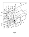
- a drive arm 10 of a wiper blade 12 (partially shown) of a motor vehicle, this arm having a generally elongate shape and being connected by its outer longitudinal end to the wiper blade 12 and by its longitudinal end inside a drive head 14.
- the drive head 14 is fixed to the upper end of a drive shaft 16 in alternating rotary scanning of the arm 10 about the pivot axis A1.
- the arm 10 includes a housing 18 forming an inner end portion of the arm and a rigid metal rod 20 forming an outer end portion of the arm.
- the inner end of the housing 18 and the drive head 14 are mounted hinged about a transverse pivot axis A2 for lifting the arm 10 of the windshield.
- the outer end of the casing 18 is fixed firmly by a narrowing 21 on the metal rod 20.
- the casing 18 of the arm 10 has, substantially along its entire length, an inverted U-shaped section (that is to say open towards the windscreen side) which defines an internal longitudinal cavity 22.
- An inner end portion of the metal rod 20 extends within the cavity 22 of the housing 18 and is secured by its inner end to one end of a wiper blade pressure spring 24. -le 12, the opposite end of the spring being connected to the drive head 14.
- the spring 24 is visible by transparency in figure 1 and better visible in figure 2 .
- the longitudinal axis of the spring 24 is substantially parallel to the longitudinal axis of the arm 10.
- this spring 24 is a helical spring in tension having several turns wound between an inner end and an outer end 28, each of these ends having a fixing hook.
- the hook of the inner end of the spring 24 is fixed to the drive head 14 and the hook of its outer end 28 is engaged and retained in a hole 30 passing through the inner end of the metal rod 20.
- the orifice 30 has here a generally oblong shape, its axis being substantially perpendicular to the longitudinal axis of the arm 10.
- the wiper blade 12 comprises means (not shown) for spraying windshield washer fluid, which are supplied with windshield washer fluid by a hose 32.
- the pipe 32 is connected to a reservoir of washing fluid (not shown) arranged inside the vehicle.
- the pipe 32 runs along the arm 10 over substantially the entire length of its housing 18, its outer end being connected to the blade 12 for the windscreen washer fluid supply of its projection means.
- the pipe 32 is attached to the arm 10 to avoid the disadvantages described in the foregoing.
- the arm 10 is equipped with clip (s) which comprise means for retaining the pipe 32 and means for attachment to the arm, these fixing means comprising resilient snap-fastening means which are configured to traverse an arm hole.
- the arm 10 is equipped with two staples 40, 40 'which are each engaged in an orifice of the metal rod 20 of the arm 10.
- the staples are not visible by the driver of the vehicle because they are housed in the cavity 22 of the housing .
- One of these orifices being the orifice 30 in which is engaged the hook of the outer end 28 of the spring 24 ( figure 2 ).
- the other orifice is an orifice 42 of the rod 20 located substantially midway between the inner end of the rod 20 and the narrowed outer end of the housing of the arm 10 ( figures 3 and 4 ).
- the staples 40, 40 ' are here substantially identical. The following description, made with reference to the figure 4 and relative to the staple 40 ', therefore also applies to the staple 40.
- the means for retaining the staple 40 'according to the invention comprise a longitudinal member 44 which defines an internal longitudinal space of engagement and retention of the pipe 32.
- a longitudinal member 44 which defines an internal longitudinal space of engagement and retention of the pipe 32.
- the internal space of the member 44 has a generally cylindrical shape and opens axially at both longitudinal ends of the body.
- the member 44 has a generally cylindrical and tubular shape and comprises an internal cylindrical surface intended to come into contact with the pipe 32.
- the internal diameter of the member 44 that is to say the diameter of its internal space, may be equal to or less than the external diameter of the pipe 32.
- the member 44 is split and open over its entire length, that is to say it has a longitudinal slot 46 ( figures 2 and 4 ), which is delimited by two longitudinal edges 48 substantially parallel and facing one another.
- the slot 46 may have a width smaller than the outside diameter of the pipe 32.
- the slot 46 opens here downwards, on the opposite side to the fastening means of the clip to the arm.
- the member 44 is elastically deformable so as to allow a separation of the edges 48 from one another, resulting in an increase in the width of the slot 46.
- This allows to engage and mount the pipe in the internal space of the member 44.
- the pipe 32 is positioned along the slot 46 and at the entrance thereof.
- a slight force exerted on the pipe 32 upwards and in a direction along a Y axis (which is substantially perpendicular to the X axis and contained in a longitudinal plane passing through the middle of the slot 46 and by the longitudinal axis X of the member) causes the tube to bear on the longitudinal edges 48 of the slot, and results in a spacing thereof, until the width of the slot is sufficient to allow the hose to pass through. the internal space of the organ 44.
- the member 44 forming the retaining means of the pipe 32, on the one hand, and the elastic detent means for attachment to the arm, on the other hand, are located on two opposite sides (here the lower and upper sides, respectively) of the staple 40 '.
- the resilient latching means of the clip 40 'according to the invention comprise two elastically deformable tabs 50 which project from an upper platform 52 of the member 44.
- the tabs 50 extend upwardly from this platform 52 and comprise at their upper free ends hooking teeth 54 which are oriented in two opposite directions along an axis Z, which here are lateral directions.
- the Z axis is here substantially perpendicular to the aforementioned longitudinal plane passing through the middle of the slot 46 and the longitudinal axis X of the member 44.
- the legs 50 each comprise a flat wall, the walls of the legs extending respectively in planes parallel to the aforementioned longitudinal plane and spaced apart from each other.
- Each wall comprises at its free upper end a substantially perpendicular flange oriented on the opposite side to the other wall and forming the attachment tooth 54 of the tab.
- Each tab 50 is elastically deformable in particular by bending in a plane substantially perpendicular to the longitudinal axis X of the member.
- the tabs 50 may thus be elastically deformed to bring their free ends to one another, or to separate them from one another.
- the side surfaces 56 oriented in opposite directions of the walls tabs 50 are at a distance D from each other which is determined according to the dimensions of the opening 42 of engagement of these tabs.
- the tabs 50 are mounted with clearance in the orifice.
- the tabs are mounted slightly prestressed in the orifice, which makes it possible to limit the movements of the staple 40 'in use.
- the width or longitudinal dimension of the tabs 50 is preferably determined so that they can cooperate by abutment with the peripheral edges of the orifice 42 and thus limit the movement of the clip vis-à-vis the rod 50, especially along the X axis.
- each tab 50 and more precisely the height H between the platform 52 and the tooth 54 (or the rim of the wall) of this tab, is determined as a function of the length of the orifice 42. or the thickness of material traversed by the orifice, which is the thickness of the rod 20 along the Y axis or the axis of the orifice.
- the height H must here be at least equal to the thickness of the rod 20 so that the tabs 50 can cooperate by snap elastically with the orifice 42 and allow their teeth 54 to abut on the upper surface of the rod 20, after the elastic return of the legs.
- the platform 52 of the member 44 must be supported on the lower surface of the rod 20 to allow the said elastic return.
- each tab 50 comprises at its free end a chamfer 58 forming a ramp for facilitating the introduction of the tab 50 into the hole 42 and the deformation thereof during this introduction.
- the tabs 50 cooperate with the orifice 42 of the rod 20 by resilient snapping.
- the mounting of the clip 40 'on the rod 20 can be achieved in the following manner.
- a force exerted on the staple 40 'in the Y direction will cause the tabs 50, which will engage in the hole 42, to bend and come together.
- the movement of the staple 40' in the Y direction is continued. until the platform 52 bears on the lower surface of the rod 20 and that the teeth 54 of the tabs 50 come on the upper surface of the rod, by elastic return of the legs, which substantially return to their position d origin in the state without constraint.
- the clip 40 ' according to the invention shown in the drawings further comprises anti-rotation means which are intended to cooperate by abutment with the arm 10, and in particular with the rod 20 of the arm, to avoid or prevent any rotational movement of the staple around the axis of the orifice 42.
- the anti-rotation means comprise two substantially parallel fingers 62 which project respectively on (lateral) sides of the member 44.
- the fingers 62 comprise facing lateral surfaces 64 which serve as surfaces bearing on the metal rod 20.
- the fingers 62 are each formed by a flat wall which extends in a plane substantially parallel to the aforementioned longitudinal plane. Thus, the fingers 62 and the tabs 50 extend substantially parallel.
- the planes of the fingers 62 are spaced from each other by a distance M slightly greater than the width of the rod 20. These planes are also spaced from the aforementioned planes of the tabs 50.
- the plane of each finger 62 is separated from the plane of the tab 50 closest by a distance N which is greater than the thickness of material between the inner side wall of the orifice 42 and the outer side wall closest to the rod 20.
- the fingers 62 extend on either side of the the rod and their internal lateral surfaces 62 are intended to cooperate by abutment with the rod 20 to limit the rotational displacements of the clip around the axis of the orifice 42.
- the clip 40 As is also visible in the drawings, the clip 40 'comprising the member 44, the tabs 50 and the fingers 62, is formed in one piece, for example plastic material.
- the arm is equipped with two clips for fixing the washing liquid circulation pipe. It is of course conceivable for an arm to be equipped with a single staple or with more than two staples, in particular depending on the length of the arm (a relatively long arm may need more staples distributed over its length than a shorter arm, to ensure a good fixation of the pipe vis-à-vis the arm).
Landscapes
- Engineering & Computer Science (AREA)
- Mechanical Engineering (AREA)
- General Engineering & Computer Science (AREA)
- Clamps And Clips (AREA)
- Supports For Pipes And Cables (AREA)
- Insertion Pins And Rivets (AREA)
Abstract
Agrafe (40') de fixation d'un tuyau (32) de circulation de fluide à un bras (10) d'entraînement d'un balai d'essuie-glace de véhicule, en particulier automobile, comprenant des moyens de retenue du tuyau et des moyens de fixation au bras, lesdits moyens de fixation étant situés sur un côté de l'agrafe opposé à celui où sont situés lesdits moyens de retenue, et en ce que les moyens de fixation comprennent des moyens d'encliquetage élastique qui sont configurés pour traverser un orifice (42) du bras.Clip (40 ') for attaching a fluid circulation pipe (32) to an arm (10) for driving a vehicle windscreen wiper blade, in particular an automobile, comprising pipe retaining means and means for attachment to the arm, said fixing means being located on one side of the clip opposite to that in which said retaining means are located, and in that the securing means comprise resilient snap means which are configured to cross an orifice (42) of the arm.
Description
La présente invention concerne une agrafe de fixation d'un tuyau de circulation de fluide à un bras d'entraînement d'un balai d'essuie-glace de véhicule, en particulier automobile, ainsi qu'un bras d'entraînement d'un balai d'essuie-glace portant au moins une telle agrafe.The present invention relates to a clip for attaching a fluid circulation pipe to a drive arm of a vehicle windscreen wiper blade, particularly a motor vehicle, as well as a drive arm of a wiper blade. wiper bearing at least one such clip.
Un balai d'essuie-glace comprend en général un corps longitudinal portant une lame d'essuyage, en général en caoutchouc, destinée à frotter contre le pare-brise d'un véhicule pour évacuer de l'eau en l'amenant en dehors du champ de vision du conducteur. Le balai est porté par un bras qui est entraîné par un moteur dans un mouvement de va-et-vient angulaire. Les moyens de liaison du balai au bras comprennent en général un connecteur qui est solidaire du corps du balai et un adaptateur qui est articulé sur le connecteur et fixé à une extrémité du bras, dont l'extrémité opposée est articulée sur le véhicule et accouplée au moteur.A wiper blade generally comprises a longitudinal body carrying a wiper blade, usually made of rubber, intended to rub against the windshield of a vehicle to evacuate water by bringing it outside the vehicle. driver's field of vision. The broom is carried by an arm which is driven by a motor in an angular back and forth motion. The linkage means of the brush to the arm generally comprise a connector which is integral with the body of the brush and an adapter which is articulated on the connector and fixed to one end of the arm, the opposite end is articulated on the vehicle and coupled to the engine.
Il est connu d'équiper un balai d'essuie-glace avec des moyens de projection de fluide, tel qu'un liquide lave-glace. Le liquide lave-glace est contenu dans un réservoir situé sous le capot du véhicule et est amené jusqu'au balai par au moins un tuyau souple qui s'étend en partie le long du bras. Le tuyau ne doit pas venir au contact du pare-brise lors des déplacements du balai. De plus, il est préférable que le tuyau ne soit pas visible par les occupants du véhicule pour une raison esthétique. Une solution connue consiste à fixer le tuyau au bras au moyen d'une agrafe qui comprend des moyens de retenue du tuyau et des moyens de fixation au bras, en général par encliquetage élastique.It is known to equip a wiper blade with fluid projection means, such as a washer fluid. The washer fluid is contained in a tank located under the hood of the vehicle and is brought to the broom by at least one flexible pipe which extends partly along the arm. The hose must not come into contact with the windshield when the broom is moving. In addition, it is preferable that the pipe is not visible to the occupants of the vehicle for an aesthetic reason. A known solution is to attach the pipe to the arm by means of a clip which comprises means for retaining the pipe and means for attachment to the arm, generally by resilient snapping.
Cependant, les agrafes de la technique antérieure ne sont pas entièrement satisfaisantes car elles sont relativement volumineuses et leur méthode de montage n'est pas simple et peut nécessiter l'utilisation d'outil spécifique. Il peut par exemple s'avérer difficile de monter manuellement une agrafe par encliquetage élastique dans deux orifices distincts d'un bras d'entraînement.However, the staples of the prior art are not entirely satisfactory because they are relatively bulky and their mounting method is not simple and may require the use of specific tool. For example, it may be difficult to manually mount an elastic snap clip into two separate ports of a drive arm.
L'invention propose une solution simple, efficace et économique à au moins une partie des problèmes de la technique antérieure.The invention provides a simple, effective and economical solution to at least some of the problems of the prior art.
L'invention propose une agrafe de fixation d'un tuyau de circulation de fluide à un bras d'entraînement d'un balai d'essuie-glace de véhicule, en particulier automobile, comprenant des moyens de retenue du tuyau et des moyens de fixation au bras, caractérisée en ce que lesdits moyens de fixation sont situés sur un côté de l'agrafe opposé à celui où sont situés lesdits moyens de retenue, et en ce que les moyens de fixation comprennent des moyens d'encliquetage élastique qui sont configurés pour traverser un orifice du bras.The invention proposes a clip for attaching a fluid circulation pipe to a driving arm of a vehicle windscreen wiper blade, in particular a motor vehicle, comprising means for retaining the pipe and fastening means. on the arm, characterized in that said fixing means are situated on one side of the clip opposite to that where said retaining means are located, and in that the fixing means comprise elastic snap-fastening means which are configured for cross an orifice of the arm.
L'agrafe est ainsi configurée pour faciliter son montage sur le bras. Les moyens de fixation et les moyens de retenue sont situés sur des côtés opposés de l'agrafe (tels que les côtés supérieur et inférieur, respectivement), ce qui permet de ne pas être gêné par les moyens de fixation lorsque l'on manipule les moyens de retenue, et inversement, de ne pas être gêné par les moyens de retenue lorsque l'on manipule les moyens de fixation. Il est par exemple envisageable de monter (et démonter) un tuyau dans les moyens de retenue de l'agrafe, sans intervenir sur ses moyens de fixation. Il est également envisageable de monter (et démonter) l'agrafe du bras sans intervenir sur les moyens de retenue qui peuvent toujours coopérer avec un tuyau.The clip is thus configured to facilitate mounting on the arm. The fixing means and the retaining means are situated on opposite sides of the clip (such as the upper and lower sides, respectively), which makes it possible not to be impeded by the fastening means when handling the clips. retaining means, and conversely, not to be hindered by the retaining means when handling the fastening means. It is for example conceivable to assemble (and disassemble) a pipe in the retaining means of the clip, without intervening on its fixing means. It is also conceivable to assemble (and disassemble) the staple of the arm without intervening on the retaining means which can always cooperate with a pipe.
Par ailleurs, selon l'invention, les moyens de fixation sont d'un type particulier car ils comprennent des moyens d'encliquetage élastique qui sont configurés pour être engagés dans un orifice du bras, et traverser cet orifice. Autrement dit, les moyens de fixation de l'agrafe sont destinés à traverser un orifice traversant du bras. Dans la présente demande, on entend par orifice traversant, un orifice qui traverse de part en part l'épaisseur de matière d'une pièce. Autrement dit, les deux extrémités d'un orifice traversant sont débouchantes au contraire d'un trou borgne qui comprend une seule extrémité traversante ou même d'une cavité qui n'a en général qu'une seule ouverture.Furthermore, according to the invention, the fastening means are of a particular type because they comprise resilient latching means which are configured to be engaged in an orifice of the arm, and through this orifice. In other words, the fastening means of the clip are intended to pass through a through hole of the arm. In this application, means through orifice, an orifice which passes through the thickness of material of a part. In other words, the two ends of a through orifice are open on the contrary of a blind hole which comprises a single through end or even a cavity which generally has only one opening.
Par ailleurs, du fait que les moyens d'encliquetage de l'agrafe coopèrent avec un orifice du bras, un seul orifice peut suffire à l'accrochage de l'agrafe au balai.Moreover, because the clipping means of the staple cooperate with an orifice of the arm, a single orifice may be sufficient to hook the staple to the blade.
De préférence, les moyens de fixation comprennent au moins une patte élastiquement déformable et comportant à une extrémité au moins une dent d'accrochage.Preferably, the fixing means comprise at least one elastically deformable tab and having at one end at least one attachment tooth.
Les moyens de fixation peuvent comprendre au moins deux pattes élastiquement déformables et comportant respectivement au moins deux dents d'accrochage qui sont orientées dans des directions sensiblement opposées. Avantageusement, la ou les pattes coopèrent par butée avec le bord périphérique de l'orifice pour limiter les déplacements de l'agrafe.The fixing means may comprise at least two elastically deformable tabs and respectively comprising at least two gripping teeth which are oriented in substantially opposite directions. Advantageously, the tab or tabs cooperate by abutment with the peripheral edge of the orifice to limit the movements of the clip.
De préférence, lesdites au moins deux pattes s'étendent respectivement dans deux plans parallèles entre eux et espacés l'un de l'autre.Preferably, said at least two tabs respectively extend in two planes parallel to each other and spaced apart from each other.
Lesdits moyens de retenue peuvent comprendre un organe longitudinal tubulaire définissant un espace longitudinal interne de logement et de retenue du tuyau. Cet organe comporte de préférence une fente longitudinale traversante configurée pour autoriser le passage du tuyau lors de son montage dans ledit espace, de préférence par encliquetage élastique. La fente débouche de préférence dans une direction opposée aux (pattes des) moyens de fixation.Said retaining means may comprise a tubular longitudinal member defining an internal longitudinal space for accommodating and retaining the pipe. This member preferably comprises a longitudinal through slot configured to allow the passage of the pipe during its mounting in said space, preferably by resilient latching. The slot preferably opens in a direction opposite to (legs of) fastening means.
La fente peut avoir une largeur inférieure au diamètre du tuyau. Cette fente peut être délimitée par deux bords longitudinaux en regard de l'organe, qui peuvent être écartés l'un de l'autre par déformation élastique de l'organe.The slot may have a width smaller than the diameter of the pipe. This slot may be delimited by two longitudinal edges facing the body, which may be spaced from each other by elastic deformation of the body.
Les plans des pattes élastiquement déformables précitées sont de préférence sensiblement parallèles à l'axe longitudinal de l'organe.The planes of the aforementioned elastically deformable tabs are preferably substantially parallel to the longitudinal axis of the member.
Ces pattes sont de préférence élastiquement déformables dans des directions contenues dans un plan sensiblement perpendiculaire à l'axe longitudinal de l'organe.These tabs are preferably elastically deformable in directions contained in a plane substantially perpendicular to the longitudinal axis of the member.
Avantageusement, l'agrafe comprend en outre des moyens d'anti-rotation de l'agrafe, qui sont configurés pour coopérer par butée avec le bras.Advantageously, the clip further comprises anti-rotation means of the clip, which are configured to cooperate by abutment with the arm.
Les moyens d'anti-rotation peuvent comprendre au moins un doigt comportant une surface d'appui. De préférence, ils comprennent deux doigts comportant respectivement deux surfaces d'appui en regard l'une de l'autre.The anti-rotation means may comprise at least one finger having a bearing surface. Preferably, they comprise two fingers respectively having two bearing surfaces facing one another.
Ces doigts peuvent s'étendre respectivement dans deux plans espacés l'un de l'autre et parallèles entre eux et à l'axe longitudinal de l'organe.These fingers may extend respectively in two planes spaced from one another and parallel to each other and to the longitudinal axis of the organ.
L'agrafe selon l'invention est de préférence formée d'une seule pièce.The clip according to the invention is preferably formed in one piece.
La présente invention concerne encore un bras d'entraînement d'un balai d'essuie-glace de véhicule, en particulier automobile, caractérisé en ce qu'il comprend au moins une agrafe telle que décrite ci-dessus, les moyens de fixation du ou de chaque agrafe étant engagés et traversant un orifice du bras.The present invention also relates to a drive arm of a vehicle wiper blade, in particular an automobile, characterized in that it comprises at least one staple as described above, the fastening means of the each staple being engaged and passing through an orifice of the arm.
De préférence, le bras comprend un carter dont au moins une partie a en section une forme en U définissant une cavité interne. Le carter est fixé à une tige rigide qui s'étend en partie à l'intérieur de la cavité et qui comprend un ou deux orifices dans lequel ou dans chacun desquels est montée une agrafe. La ou chaque agrafe peut être intégralement logée dans la cavité du carter et donc ne pas être visible pour le conducteur du véhicule.Preferably, the arm comprises a casing of which at least a portion has a U-shaped section defining an internal cavity. The housing is attached to a rigid rod which extends partly inside the cavity and which comprises one or two orifices in which or in each of which is mounted a clip. The or each staple can be fully housed in the housing cavity and thus not be visible to the driver of the vehicle.
Un ressort peut être monté dans la cavité interne du carter et comprendre une extrémité engagée dans l'un des orifices de montage des agrafes. On comprend donc qu'un même orifice sert au montage du ressort et d'une agrafe, ce qui est particulièrement avantageux en termes d'encombrement.A spring may be mounted in the internal cavity of the housing and include an end engaged in one of the mounting holes of the clips. It is therefore understood that the same orifice serves for mounting the spring and a clip, which is particularly advantageous in terms of space.
L'invention sera mieux comprise et d'autres détails, caractéristiques et avantages de l'invention apparaîtront plus clairement à la lecture de la description suivante faite à titre d'exemple non limitatif et en référence aux dessins annexés, dans lesquels :
- la
figure 1 est une vue en perspective d'un bras d'entraînement d'un balai d'essuie-glace de véhicule automobile, ce bras comportant des agrafes selon l'invention de fixation d'un tuyau de circulation de fluide ; - la
figure 2 est une vue en perspective et à plus grande échelle d'une première agrafe du bras de lafigure 1 ; - la
figure 3 est une vue en perspective et à plus grande échelle d'une seconde agrafe du bras de lafigure 1 ; et - la
figure 4 est une autre vue en perspective et à encore plus grande échelle de la seconde agrafe du bras de lafigure 1 .
- the
figure 1 is a perspective view of a drive arm of a wiper blade of a motor vehicle, said arm having staples according to the invention for fixing a fluid circulation pipe; - the
figure 2 is a perspective view and on a larger scale of a first clip of the arm of thefigure 1 ; - the
figure 3 is a perspective view and on a larger scale of a second staple of the arm of thefigure 1 ; and - the
figure 4 is another perspective view and on even larger scale the second staple of the arm of thefigure 1 .
Il faut noter que les figures exposent l'invention de manière détaillée pour mettre en oeuvre l'invention, lesdites figures pouvant bien entendu servir à mieux définir l'invention le cas échéant.It should be noted that the figures disclose the invention in detail to implement the invention, said figures can of course be used to better define the invention where appropriate.
Dans la description qui suit, les dénominations longitudinales ou latérales se réfèrent à l'orientation d'un bras d'entraînement d'un balai d'essuie-glace. La direction longitudinale correspond à l'axe principal du bras dans lequel il s'étend, alors que les orientations latérales correspondent à des droites concourantes, c'est-à-dire qui croisent la direction longitudinale, notamment perpendiculaires à l'axe longitudinal du bras. Pour les directions longitudinales, les dénominations extérieure ou intérieure s'apprécient par rapport au point de fixation du bras sur le véhicule, la dénomination intérieure correspondant à l'extrémité du bras fixée au véhicule. Enfin, les directions référencées comme supérieures ou inférieures correspondent à des orientations perpendiculaires au plan de rotation du bras, la dénomination inférieure contenant le plan du pare-brise.In the following description, the longitudinal or lateral designations refer to the orientation of a drive arm of a wiper blade. The longitudinal direction corresponds to the main axis of the arm in which it extends, while the lateral orientations correspond to intersecting straight lines, that is to say which intersect the longitudinal direction, in particular perpendicular to the longitudinal axis of the longitudinal axis. arms. For the longitudinal directions, the outer or inner names are assessed relative to the attachment point of the arm on the vehicle, the inner name corresponding to the end of the arm attached to the vehicle. Finally, the directions referenced as superior or lower correspond to orientations perpendicular to the plane of rotation of the arm, the lower denomination containing the plane of the windshield.
Il est illustré à la
La tête d'entraînement 14 est fixée à l'extrémité supérieure d'un arbre 16 d'entraînement en balayage rotatif alterné du bras 10 autour de l'axe de pivotement A1.The
Le bras 10 comprend un carter 18 formant une partie d'extrémité intérieure du bras et une tige métallique 20 rigide formant une partie d'extrémité extérieure du bras.The
L'extrémité intérieure du carter 18 et la tête d'entraînement 14 sont montés articulés autour d'un axe de pivotement transversal A2 permettant de soulever le bras 10 du pare-brise.The inner end of the
L'extrémité extérieure du carter 18 est fixée solidement par un rétrécissement 21 sur la tige métallique 20.The outer end of the
Le carter 18 du bras 10 a, sensiblement sur toute sa longueur, une section en forme de U renversée (c'est-à-dire ouvert du côté du pare-brise) qui définit une cavité longitudinale interne 22.The
Une partie d'extrémité intérieure de la tige métallique 20 s'étend à l'intérieur de la cavité 22 du carter 18 et est fixée par son extrémité intérieure à une extrémité d'un ressort 24 de pression d'essuyage du balai d'essuie-glace 12, l'extrémité opposée du ressort étant reliée à la tête d'entraînement 14. Le ressort 24 est visible par transparence en
De façon connue en soi, ce ressort 24 est un ressort hélicoïdal en traction présentant plusieurs spires enroulées entre une extrémité intérieure et une extrémité extérieure 28, chacune de ces extrémités présentant un crochet de fixation.In a manner known per se, this
Le crochet de l'extrémité intérieure du ressort 24 est fixé à la tête d'entraînement 14 et le crochet de son extrémité extérieure 28 est engagé et retenu dans un orifice 30 traversant de l'extrémité intérieure de la tige métallique 20. L'orifice 30 a ici une forme générale oblongue, son axe étant sensiblement perpendiculaire à l'axe longitudinal du bras 10.The hook of the inner end of the
Le balai d'essuie-glace 12 comporte des moyens (non représentés) de projection de liquide lave-glace, qui sont alimentés en liquide lave-glace par un tuyau souple 32. De manière connue, le tuyau 32 est relié à un réservoir de liquide lave-glace (non représenté) agencé à l'intérieur du véhicule.The
Comme on le voit sur la
Le tuyau 32 est fixé au bras 10 pour éviter les inconvénients décrits dans ce qui précède. Selon l'invention, le bras 10 est équipé d'agrafe(s) qui comprennent des moyens de retenue du tuyau 32 et des moyens de fixation au bras, ces moyens de fixation comprenant des moyens d'encliquetage élastique qui sont configurés pour traverser un orifice du bras.The
Dans le mode de réalisation de l'invention représenté aux
Les agrafes 40, 40' sont ici sensiblement identiques. La description qui suit, fait en référence à la
Comme cela est mieux visible en
Dans l'exemple représenté, l'organe 44 a une forme générale cylindrique et tubulaire et comprend une surface cylindrique interne destinée à venir au contact du tuyau 32. Le diamètre interne de l'organe 44, c'est-à-dire le diamètre de son espace interne, peut être égal ou inférieur au diamètre externe du tuyau 32.In the example shown, the
L'organe 44 est fendu et ouvert sur toute sa longueur, c'est-à-dire qu'il comporte une fente longitudinale 46 traversante (
L'organe 44 est élastiquement déformable de façon à autoriser un écartement des bords 48 l'un de l'autre, se traduisant par une augmentation de la largeur de la fente 46. Ceci permet d'engager et de monter le tuyau dans l'espace interne de l'organe 44. Pour cela, le tuyau 32 est positionné le long de la fente 46 et à l'entrée de celle-ci. Une légère force exercée sur le tuyau 32 vers le haut et dans une direction le long d'un axe Y (qui est sensiblement perpendiculaire à l'axe X et contenu dans un plan longitudinal passant par le milieu de la fente 46 et par l'axe longitudinal X de l'organe) provoque l'appui du tuyau sur les bords longitudinaux 48 de la fente, et se traduit par un écartement de ceux-ci, jusqu'à ce que la largeur de la fente soit suffisante pour laisser passer le tuyau dans l'espace interne de l'organe 44.The
L'organe 44 formant les moyens de retenue du tuyau 32, d'une part, et les moyens d'encliquetage élastique permettant la fixation au bras, d'autre part, sont situés sur deux côtés opposés (ici les côtés inférieur et supérieur, respectivement) de l'agrafe 40'.The
Dans l'exemple représenté, les moyens d'encliquetage élastique de l'agrafe 40' selon l'invention comprennent deux pattes 50 élastiquement déformables, qui sont en saillie sur une plate-forme supérieure 52 de l'organe 44. Les pattes 50 s'étendent vers le haut depuis cette plate-forme 52 et comprennent à leurs extrémités libres supérieures des dents d'accrochage 54 qui sont orientées dans deux directions opposées le long d'un axe Z, qui sont ici des directions latérales. L'axe Z est ici sensiblement perpendiculaire au plan longitudinal précité passant par le milieu de la fente 46 et par l'axe longitudinal X de l'organe 44.In the example shown, the resilient latching means of the clip 40 'according to the invention comprise two elastically
Les pattes 50 comprennent chacune une paroi plane, les parois des pattes s'étendant respectivement dans des plans parallèles au plan longitudinal précité et espacés l'un de l'autre. Chaque paroi comprend à son extrémité supérieure libre un rebord sensiblement perpendiculaire orienté du côté opposé à l'autre paroi et formant la dent d'accrochage 54 de la patte.The
Chaque patte 50 est élastiquement déformable notamment par flexion dans un plan sensiblement perpendiculaire à l'axe longitudinal X de l'organe. Les pattes 50 peuvent ainsi être élastiquement déformées pour rapprocher leurs extrémités libres l'une de l'autre, ou pour les écarter l'une de l'autre.Each
En position sensiblement de repos représentée en
Dans le cas où l'orifice 42 a une dimension transversale supérieure à la distance D, les pattes 50 sont montées avec jeu dans l'orifice. Dans le cas contraire, les pattes sont montées légèrement précontraintes dans l'orifice, ce qui permet de limiter les déplacements de l'agrafe 40' en utilisation. De plus, la largeur ou dimension longitudinale des pattes 50 est de préférence déterminée pour que celles-ci puissent coopérer par butée avec les bords périphériques de l'orifice 42 et ainsi limiter les déplacements de l'agrafe vis-à-vis de la tige 50, en particulier le long de l'axe X.In the case where the
Par ailleurs, la hauteur de chaque patte 50, et plus précisément la hauteur H entre la plate-forme 52 et la dent 54 (ou le rebord de la paroi) de cette patte, est déterminée en fonction de la longueur de l'orifice 42 ou de l'épaisseur de matière traversée par l'orifice, qui est l'épaisseur de la tige 20 le long de l'axe Y ou de l'axe de l'orifice.Moreover, the height of each
La hauteur H doit ici être au moins égale à l'épaisseur de la tige 20 de façon à ce que les pattes 50 puissent coopérer par encliquetage élastique avec l'orifice 42 et autoriser leurs dents 54 à venir en appui sur la surface supérieure de la tige 20, après le retour élastique des pattes.The height H must here be at least equal to the thickness of the
Dans le cas où la hauteur H est sensiblement égale à l'épaisseur de la tige 20, la plate-forme 52 de l'organe 44 doit être en appui sur la surface inférieure de la tige 20 pour autoriser le retour élastique précité.In the case where the height H is substantially equal to the thickness of the
De plus, la dent 54 de chaque patte 50 comprend à son extrémité libre un chanfrein 58 formant une rampe destinée à faciliter l'introduction de la patte 50 dans l'orifice 42 ainsi que la déformation de celle-ci lors de cette introduction.In addition, the
Les pattes 50 coopèrent avec l'orifice 42 de la tige 20 par encliquetage élastique. Le montage de l'agrafe 40' sur la tige 20 peut être réalisé de la façon suivante. L'agrafe 40' est positionnée sous la tige 20 de façon à ce que l'axe longitudinal X de l'organe 44 soit sensiblement parallèle à l'axe longitudinal du bras 10 et que les pattes 50 soient situées en dessous et en regard de l'orifice 42. L'agrafe 40' est ensuite déplacée vers la tige 20 de façon à ce que les pattes 50 prennent appui par leurs chanfreins 58 sur les bords longitudinaux inférieurs 60 en regard de l'orifice 42. Une force exercée sur l'agrafe 40' dans la direction Y va provoquer le fléchissement et le rapprochement des pattes 50, qui vont s'engager dans l'orifice 42. Le déplacement de l'agrafe 40' dans la direction Y est poursuivi jusqu'à ce que la plate-forme 52 prenne appui sur la surface inférieure de la tige 20 et que les dents 54 des pattes 50 viennent sur la surface supérieure de la tige, par retour élastique des pattes, qui reviennent sensiblement dans leur position d'origine à l'état sans contrainte.The
L'agrafe 40' selon l'invention représentée dans les dessins comprend en outre des moyens d'anti-rotation qui sont destinés à coopérer par butée avec le bras 10, et en particulier avec la tige 20 du bras, pour éviter voire empêcher tout déplacement en rotation de l'agrafe autour de l'axe de l'orifice 42.The clip 40 'according to the invention shown in the drawings further comprises anti-rotation means which are intended to cooperate by abutment with the
Dans l'exemple représenté, les moyens d'anti-rotation comprennent deux doigts 62 sensiblement parallèles qui sont en saillie respectivement sur des côtés (latéraux) de l'organe 44. Les doigts 62 comportent des surfaces latérales 64 en regard qui servent de surfaces d'appui sur la tige métallique 20.In the example shown, the anti-rotation means comprise two substantially
Les doigts 62 sont chacun formés par une paroi plane qui s'étend dans un plan sensiblement parallèle au plan longitudinal précité. Ainsi, les doigts 62 et les pattes 50 s'étendent sensiblement parallèlement. Les plans des doigts 62 sont espacés l'un de l'autre d'une distance M légèrement supérieure à la largeur de la tige 20. Ces plans sont également espacés des plans précités des pattes 50. Le plan de chaque doigt 62 est séparé du plan de la patte 50 la plus proche par une distance N qui est supérieure à l'épaisseur de matière entre la paroi latérale interne de l'orifice 42 et la paroi latérale externe la plus proche de la tige 20.The
Comme on le voit dans les dessins, après le montage de l'agrafe 40' dans l'orifice 42 de la tige 20, les doigts 62 s'étendent de part et d'autre de la tige et leurs surfaces latérales internes 62 sont destinées à coopérer par butée avec la tige 20 pour limiter les déplacements en rotation de l'agrafe autour de l'axe de l'orifice 42.As can be seen in the drawings, after mounting the clip 40 'in the
Comme cela est également visible dans les dessins, l'agrafe 40' comportant l'organe 44, les pattes 50 et les doigts 62, est formée d'une seule pièce, par exemple en matériau plastique.As is also visible in the drawings, the clip 40 'comprising the
Dans l'exemple décrit dans ce qui précède, le bras est équipé de deux agrafes de fixation du tuyau de circulation de liquide lave glace. Il est bien entendu envisageable qu'un bras soit équipé d'une seule agrafe ou de plus de deux agrafes, notamment en fonction de la longueur du bras (un bras relativement long peut avoir besoin de plus d'agrafes répartis sur sa longueur qu'un bras plus court, pour assurer une bonne fixation du tuyau vis-à-vis du bras).In the example described in the foregoing, the arm is equipped with two clips for fixing the washing liquid circulation pipe. It is of course conceivable for an arm to be equipped with a single staple or with more than two staples, in particular depending on the length of the arm (a relatively long arm may need more staples distributed over its length than a shorter arm, to ensure a good fixation of the pipe vis-à-vis the arm).
Claims (15)
Applications Claiming Priority (1)
| Application Number | Priority Date | Filing Date | Title |
|---|---|---|---|
| FR1362353A FR3014529B1 (en) | 2013-12-10 | 2013-12-10 | FLUID CIRCULATION PIPE FASTENING STATION WITH A DRIVE ARM OF A VEHICLE WIPER BLADE |
Publications (2)
| Publication Number | Publication Date |
|---|---|
| EP2883761A1 true EP2883761A1 (en) | 2015-06-17 |
| EP2883761B1 EP2883761B1 (en) | 2022-03-16 |
Family
ID=50289907
Family Applications (1)
| Application Number | Title | Priority Date | Filing Date |
|---|---|---|---|
| EP14195320.8A Active EP2883761B1 (en) | 2013-12-10 | 2014-11-28 | Clip for attaching a fluid circulation pipe to a drive arm of a vehicle windscreen wiper |
Country Status (3)
| Country | Link |
|---|---|
| EP (1) | EP2883761B1 (en) |
| CN (1) | CN104691510B (en) |
| FR (1) | FR3014529B1 (en) |
Cited By (1)
| Publication number | Priority date | Publication date | Assignee | Title |
|---|---|---|---|---|
| DE102015224620A1 (en) * | 2015-12-08 | 2017-06-08 | Robert Bosch Gmbh | Hose holder for a wiper arm, a wiper arm with a hose holder, as well as a method for producing such a hose holder |
Families Citing this family (3)
| Publication number | Priority date | Publication date | Assignee | Title |
|---|---|---|---|---|
| DE102017119223A1 (en) * | 2017-08-23 | 2019-02-28 | Valeo Wischersysteme Gmbh | Wiper arm device for motor vehicles |
| DE102017130938A1 (en) * | 2017-12-21 | 2019-07-11 | Valeo Wischersysteme Gmbh | Wiper arm device for cleaning a vehicle window and use of the wiper arm |
| FR3083502B1 (en) * | 2018-07-09 | 2023-05-12 | Valeo Systemes Dessuyage | DRIVE ARM FOR A WIPER BLADE FOR A MOTOR VEHICLE |
Citations (5)
| Publication number | Priority date | Publication date | Assignee | Title |
|---|---|---|---|---|
| FR2119456A6 (en) * | 1962-08-31 | 1972-08-04 | Ft Products Ltd | |
| FR2163062A5 (en) * | 1971-11-26 | 1973-07-20 | Clipco | |
| JP2006007971A (en) * | 2004-06-25 | 2006-01-12 | Asmo Co Ltd | Wiper device |
| EP2591958A1 (en) * | 2011-11-09 | 2013-05-15 | Valeo Systèmes d'Essuyage | Windscreen wiper and device for holding a pipe for supplying a windscreen-washing product against an actuating arm of the wiper blade |
| US20130119208A1 (en) * | 2004-04-30 | 2013-05-16 | Hellermanntyton Corporation | Fir tree mount for cable ties |
Family Cites Families (3)
| Publication number | Priority date | Publication date | Assignee | Title |
|---|---|---|---|---|
| FR2547548B2 (en) * | 1983-06-20 | 1988-06-03 | Lamaudiere Paul | SPRAY SPRAY FOR WIPER BLADE |
| DE4117106C2 (en) * | 1991-05-25 | 2000-03-09 | Teves Gmbh Alfred | Wiper arm, in particular for motor vehicles |
| GB0204031D0 (en) * | 2002-02-21 | 2002-04-03 | Trico Ltd | Improvements relating to hose retainers |
-
2013
- 2013-12-10 FR FR1362353A patent/FR3014529B1/en active Active
-
2014
- 2014-11-28 EP EP14195320.8A patent/EP2883761B1/en active Active
- 2014-12-10 CN CN201410751802.6A patent/CN104691510B/en active Active
Patent Citations (5)
| Publication number | Priority date | Publication date | Assignee | Title |
|---|---|---|---|---|
| FR2119456A6 (en) * | 1962-08-31 | 1972-08-04 | Ft Products Ltd | |
| FR2163062A5 (en) * | 1971-11-26 | 1973-07-20 | Clipco | |
| US20130119208A1 (en) * | 2004-04-30 | 2013-05-16 | Hellermanntyton Corporation | Fir tree mount for cable ties |
| JP2006007971A (en) * | 2004-06-25 | 2006-01-12 | Asmo Co Ltd | Wiper device |
| EP2591958A1 (en) * | 2011-11-09 | 2013-05-15 | Valeo Systèmes d'Essuyage | Windscreen wiper and device for holding a pipe for supplying a windscreen-washing product against an actuating arm of the wiper blade |
Cited By (2)
| Publication number | Priority date | Publication date | Assignee | Title |
|---|---|---|---|---|
| DE102015224620A1 (en) * | 2015-12-08 | 2017-06-08 | Robert Bosch Gmbh | Hose holder for a wiper arm, a wiper arm with a hose holder, as well as a method for producing such a hose holder |
| US10759390B2 (en) | 2015-12-08 | 2020-09-01 | Robert Bosch Gmbh | Tube holder for a wiper arm, wiper arm having a tube holder, and method for producing such a tube holder |
Also Published As
| Publication number | Publication date |
|---|---|
| FR3014529A1 (en) | 2015-06-12 |
| CN104691510B (en) | 2020-05-22 |
| CN104691510A (en) | 2015-06-10 |
| FR3014529B1 (en) | 2016-05-06 |
| EP2883761B1 (en) | 2022-03-16 |
Similar Documents
| Publication | Publication Date | Title |
|---|---|---|
| EP2591958B1 (en) | Windscreen wiper and device for holding a pipe for supplying a windscreen-washing product against an actuating arm of the wiper blade | |
| EP2883761B1 (en) | Clip for attaching a fluid circulation pipe to a drive arm of a vehicle windscreen wiper | |
| EP3040247A1 (en) | Wiper arm fitted with a spray nozzle | |
| EP3165416B1 (en) | Adapter for a motor vehicle windscreen wiper | |
| EP3168093B1 (en) | Adapter for a motor vehicle windscreen wiper | |
| EP3231673A1 (en) | System for wiping a windscreen of a vehicle | |
| EP2965958B1 (en) | Assembly comprising a mechanical connector and a cannula for a vehicle windscreen-wiper blade | |
| EP2965957B1 (en) | Pivot link for a vehicle wiper blade | |
| EP3165417B1 (en) | Adapter for a motor vehicle windscreen wiper | |
| EP2987689A1 (en) | Leaf spring for a vehicle wiper blade | |
| FR3031712A1 (en) | ICE WIPER COVER CONFIGURE TO COVER A TERMINAL PART OF A WIPER ARM | |
| EP2883760B1 (en) | Clip for attaching a fluid circulation pipe to a drive arm of a vehicle windscreen wiper | |
| EP3012163A1 (en) | Device for spraying windscreen washer liquid for a wiper of a vehicle windscreen wiping system | |
| WO2016150739A1 (en) | Holder for drive arm of a windscreen-wiper blade | |
| FR3065762B1 (en) | ROD FOR WINDSCREEN ACTUATING PIPING SYSTEM AND METHOD FOR ASSEMBLING SAME | |
| EP3375675A1 (en) | Cap, connecting device for mounting a windscreen wiper on a corresponding windscreen wiper arm and windscreen wiping system | |
| EP3434536B1 (en) | Attachment device for a windscreen wiper linkage system | |
| EP3402703B1 (en) | Adapter for connecting a wiper blade to a drive arm | |
| WO2023110974A1 (en) | End cap and windscreen-wiper blade for a motor vehicle | |
| FR3113268A1 (en) | Device for maintaining a windscreen washer fluid supply pipe | |
| FR3130721A1 (en) | End cap and wiper blade for automotive vehicle | |
| FR3043614A1 (en) | ADAPTER FOR A WINDSCREEN WIPER OF A MOTOR VEHICLE |
Legal Events
| Date | Code | Title | Description |
|---|---|---|---|
| PUAI | Public reference made under article 153(3) epc to a published international application that has entered the european phase |
Free format text: ORIGINAL CODE: 0009012 |
|
| 17P | Request for examination filed |
Effective date: 20141128 |
|
| AK | Designated contracting states |
Kind code of ref document: A1 Designated state(s): AL AT BE BG CH CY CZ DE DK EE ES FI FR GB GR HR HU IE IS IT LI LT LU LV MC MK MT NL NO PL PT RO RS SE SI SK SM TR |
|
| AX | Request for extension of the european patent |
Extension state: BA ME |
|
| STAA | Information on the status of an ep patent application or granted ep patent |
Free format text: STATUS: EXAMINATION IS IN PROGRESS |
|
| 17Q | First examination report despatched |
Effective date: 20190326 |
|
| STAA | Information on the status of an ep patent application or granted ep patent |
Free format text: STATUS: EXAMINATION IS IN PROGRESS |
|
| GRAP | Despatch of communication of intention to grant a patent |
Free format text: ORIGINAL CODE: EPIDOSNIGR1 |
|
| STAA | Information on the status of an ep patent application or granted ep patent |
Free format text: STATUS: GRANT OF PATENT IS INTENDED |
|
| GRAJ | Information related to disapproval of communication of intention to grant by the applicant or resumption of examination proceedings by the epo deleted |
Free format text: ORIGINAL CODE: EPIDOSDIGR1 |
|
| GRAP | Despatch of communication of intention to grant a patent |
Free format text: ORIGINAL CODE: EPIDOSNIGR1 |
|
| STAA | Information on the status of an ep patent application or granted ep patent |
Free format text: STATUS: GRANT OF PATENT IS INTENDED |
|
| INTG | Intention to grant announced |
Effective date: 20211013 |
|
| INTG | Intention to grant announced |
Effective date: 20211026 |
|
| GRAS | Grant fee paid |
Free format text: ORIGINAL CODE: EPIDOSNIGR3 |
|
| GRAA | (expected) grant |
Free format text: ORIGINAL CODE: 0009210 |
|
| STAA | Information on the status of an ep patent application or granted ep patent |
Free format text: STATUS: THE PATENT HAS BEEN GRANTED |
|
| AK | Designated contracting states |
Kind code of ref document: B1 Designated state(s): AL AT BE BG CH CY CZ DE DK EE ES FI FR GB GR HR HU IE IS IT LI LT LU LV MC MK MT NL NO PL PT RO RS SE SI SK SM TR |
|
| REG | Reference to a national code |
Ref country code: GB Ref legal event code: FG4D Free format text: NOT ENGLISH |
|
| REG | Reference to a national code |
Ref country code: CH Ref legal event code: EP |
|
| REG | Reference to a national code |
Ref country code: IE Ref legal event code: FG4D Free format text: LANGUAGE OF EP DOCUMENT: FRENCH |
|
| REG | Reference to a national code |
Ref country code: DE Ref legal event code: R096 Ref document number: 602014082848 Country of ref document: DE |
|
| REG | Reference to a national code |
Ref country code: AT Ref legal event code: REF Ref document number: 1475675 Country of ref document: AT Kind code of ref document: T Effective date: 20220415 |
|
| REG | Reference to a national code |
Ref country code: LT Ref legal event code: MG9D |
|
| REG | Reference to a national code |
Ref country code: NL Ref legal event code: MP Effective date: 20220316 |
|
| PG25 | Lapsed in a contracting state [announced via postgrant information from national office to epo] |
Ref country code: SE Free format text: LAPSE BECAUSE OF FAILURE TO SUBMIT A TRANSLATION OF THE DESCRIPTION OR TO PAY THE FEE WITHIN THE PRESCRIBED TIME-LIMIT Effective date: 20220316 Ref country code: RS Free format text: LAPSE BECAUSE OF FAILURE TO SUBMIT A TRANSLATION OF THE DESCRIPTION OR TO PAY THE FEE WITHIN THE PRESCRIBED TIME-LIMIT Effective date: 20220316 Ref country code: NO Free format text: LAPSE BECAUSE OF FAILURE TO SUBMIT A TRANSLATION OF THE DESCRIPTION OR TO PAY THE FEE WITHIN THE PRESCRIBED TIME-LIMIT Effective date: 20220616 Ref country code: LT Free format text: LAPSE BECAUSE OF FAILURE TO SUBMIT A TRANSLATION OF THE DESCRIPTION OR TO PAY THE FEE WITHIN THE PRESCRIBED TIME-LIMIT Effective date: 20220316 Ref country code: HR Free format text: LAPSE BECAUSE OF FAILURE TO SUBMIT A TRANSLATION OF THE DESCRIPTION OR TO PAY THE FEE WITHIN THE PRESCRIBED TIME-LIMIT Effective date: 20220316 Ref country code: BG Free format text: LAPSE BECAUSE OF FAILURE TO SUBMIT A TRANSLATION OF THE DESCRIPTION OR TO PAY THE FEE WITHIN THE PRESCRIBED TIME-LIMIT Effective date: 20220616 |
|
| REG | Reference to a national code |
Ref country code: AT Ref legal event code: MK05 Ref document number: 1475675 Country of ref document: AT Kind code of ref document: T Effective date: 20220316 |
|
| PG25 | Lapsed in a contracting state [announced via postgrant information from national office to epo] |
Ref country code: LV Free format text: LAPSE BECAUSE OF FAILURE TO SUBMIT A TRANSLATION OF THE DESCRIPTION OR TO PAY THE FEE WITHIN THE PRESCRIBED TIME-LIMIT Effective date: 20220316 Ref country code: GR Free format text: LAPSE BECAUSE OF FAILURE TO SUBMIT A TRANSLATION OF THE DESCRIPTION OR TO PAY THE FEE WITHIN THE PRESCRIBED TIME-LIMIT Effective date: 20220617 Ref country code: FI Free format text: LAPSE BECAUSE OF FAILURE TO SUBMIT A TRANSLATION OF THE DESCRIPTION OR TO PAY THE FEE WITHIN THE PRESCRIBED TIME-LIMIT Effective date: 20220316 |
|
| PG25 | Lapsed in a contracting state [announced via postgrant information from national office to epo] |
Ref country code: NL Free format text: LAPSE BECAUSE OF FAILURE TO SUBMIT A TRANSLATION OF THE DESCRIPTION OR TO PAY THE FEE WITHIN THE PRESCRIBED TIME-LIMIT Effective date: 20220316 |
|
| PG25 | Lapsed in a contracting state [announced via postgrant information from national office to epo] |
Ref country code: SM Free format text: LAPSE BECAUSE OF FAILURE TO SUBMIT A TRANSLATION OF THE DESCRIPTION OR TO PAY THE FEE WITHIN THE PRESCRIBED TIME-LIMIT Effective date: 20220316 Ref country code: SK Free format text: LAPSE BECAUSE OF FAILURE TO SUBMIT A TRANSLATION OF THE DESCRIPTION OR TO PAY THE FEE WITHIN THE PRESCRIBED TIME-LIMIT Effective date: 20220316 Ref country code: RO Free format text: LAPSE BECAUSE OF FAILURE TO SUBMIT A TRANSLATION OF THE DESCRIPTION OR TO PAY THE FEE WITHIN THE PRESCRIBED TIME-LIMIT Effective date: 20220316 Ref country code: PT Free format text: LAPSE BECAUSE OF FAILURE TO SUBMIT A TRANSLATION OF THE DESCRIPTION OR TO PAY THE FEE WITHIN THE PRESCRIBED TIME-LIMIT Effective date: 20220718 Ref country code: ES Free format text: LAPSE BECAUSE OF FAILURE TO SUBMIT A TRANSLATION OF THE DESCRIPTION OR TO PAY THE FEE WITHIN THE PRESCRIBED TIME-LIMIT Effective date: 20220316 Ref country code: EE Free format text: LAPSE BECAUSE OF FAILURE TO SUBMIT A TRANSLATION OF THE DESCRIPTION OR TO PAY THE FEE WITHIN THE PRESCRIBED TIME-LIMIT Effective date: 20220316 Ref country code: CZ Free format text: LAPSE BECAUSE OF FAILURE TO SUBMIT A TRANSLATION OF THE DESCRIPTION OR TO PAY THE FEE WITHIN THE PRESCRIBED TIME-LIMIT Effective date: 20220316 Ref country code: AT Free format text: LAPSE BECAUSE OF FAILURE TO SUBMIT A TRANSLATION OF THE DESCRIPTION OR TO PAY THE FEE WITHIN THE PRESCRIBED TIME-LIMIT Effective date: 20220316 |
|
| PG25 | Lapsed in a contracting state [announced via postgrant information from national office to epo] |
Ref country code: PL Free format text: LAPSE BECAUSE OF FAILURE TO SUBMIT A TRANSLATION OF THE DESCRIPTION OR TO PAY THE FEE WITHIN THE PRESCRIBED TIME-LIMIT Effective date: 20220316 Ref country code: IS Free format text: LAPSE BECAUSE OF FAILURE TO SUBMIT A TRANSLATION OF THE DESCRIPTION OR TO PAY THE FEE WITHIN THE PRESCRIBED TIME-LIMIT Effective date: 20220716 Ref country code: AL Free format text: LAPSE BECAUSE OF FAILURE TO SUBMIT A TRANSLATION OF THE DESCRIPTION OR TO PAY THE FEE WITHIN THE PRESCRIBED TIME-LIMIT Effective date: 20220316 |
|
| REG | Reference to a national code |
Ref country code: DE Ref legal event code: R097 Ref document number: 602014082848 Country of ref document: DE |
|
| PLBE | No opposition filed within time limit |
Free format text: ORIGINAL CODE: 0009261 |
|
| STAA | Information on the status of an ep patent application or granted ep patent |
Free format text: STATUS: NO OPPOSITION FILED WITHIN TIME LIMIT |
|
| PG25 | Lapsed in a contracting state [announced via postgrant information from national office to epo] |
Ref country code: DK Free format text: LAPSE BECAUSE OF FAILURE TO SUBMIT A TRANSLATION OF THE DESCRIPTION OR TO PAY THE FEE WITHIN THE PRESCRIBED TIME-LIMIT Effective date: 20220316 |
|
| 26N | No opposition filed |
Effective date: 20221219 |
|
| PG25 | Lapsed in a contracting state [announced via postgrant information from national office to epo] |
Ref country code: SI Free format text: LAPSE BECAUSE OF FAILURE TO SUBMIT A TRANSLATION OF THE DESCRIPTION OR TO PAY THE FEE WITHIN THE PRESCRIBED TIME-LIMIT Effective date: 20220316 |
|
| PG25 | Lapsed in a contracting state [announced via postgrant information from national office to epo] |
Ref country code: MC Free format text: LAPSE BECAUSE OF FAILURE TO SUBMIT A TRANSLATION OF THE DESCRIPTION OR TO PAY THE FEE WITHIN THE PRESCRIBED TIME-LIMIT Effective date: 20220316 |
|
| REG | Reference to a national code |
Ref country code: CH Ref legal event code: PL |
|
| P01 | Opt-out of the competence of the unified patent court (upc) registered |
Effective date: 20230528 |
|
| GBPC | Gb: european patent ceased through non-payment of renewal fee |
Effective date: 20221128 |
|
| REG | Reference to a national code |
Ref country code: BE Ref legal event code: MM Effective date: 20221130 |
|
| PG25 | Lapsed in a contracting state [announced via postgrant information from national office to epo] |
Ref country code: LI Free format text: LAPSE BECAUSE OF NON-PAYMENT OF DUE FEES Effective date: 20221130 Ref country code: IT Free format text: LAPSE BECAUSE OF FAILURE TO SUBMIT A TRANSLATION OF THE DESCRIPTION OR TO PAY THE FEE WITHIN THE PRESCRIBED TIME-LIMIT Effective date: 20220316 Ref country code: CH Free format text: LAPSE BECAUSE OF NON-PAYMENT OF DUE FEES Effective date: 20221130 |
|
| PG25 | Lapsed in a contracting state [announced via postgrant information from national office to epo] |
Ref country code: LU Free format text: LAPSE BECAUSE OF NON-PAYMENT OF DUE FEES Effective date: 20221128 |
|
| PG25 | Lapsed in a contracting state [announced via postgrant information from national office to epo] |
Ref country code: IE Free format text: LAPSE BECAUSE OF NON-PAYMENT OF DUE FEES Effective date: 20221128 Ref country code: GB Free format text: LAPSE BECAUSE OF NON-PAYMENT OF DUE FEES Effective date: 20221128 |
|
| PG25 | Lapsed in a contracting state [announced via postgrant information from national office to epo] |
Ref country code: BE Free format text: LAPSE BECAUSE OF NON-PAYMENT OF DUE FEES Effective date: 20221130 |
|
| PGFP | Annual fee paid to national office [announced via postgrant information from national office to epo] |
Ref country code: FR Payment date: 20231124 Year of fee payment: 10 Ref country code: DE Payment date: 20231107 Year of fee payment: 10 |
|
| PG25 | Lapsed in a contracting state [announced via postgrant information from national office to epo] |
Ref country code: HU Free format text: LAPSE BECAUSE OF FAILURE TO SUBMIT A TRANSLATION OF THE DESCRIPTION OR TO PAY THE FEE WITHIN THE PRESCRIBED TIME-LIMIT; INVALID AB INITIO Effective date: 20141128 |
|
| PG25 | Lapsed in a contracting state [announced via postgrant information from national office to epo] |
Ref country code: CY Free format text: LAPSE BECAUSE OF FAILURE TO SUBMIT A TRANSLATION OF THE DESCRIPTION OR TO PAY THE FEE WITHIN THE PRESCRIBED TIME-LIMIT Effective date: 20220316 |