EP2883688A1 - Carter annulaire composite de compresseur de turbomachine - Google Patents
Carter annulaire composite de compresseur de turbomachine Download PDFInfo
- Publication number
- EP2883688A1 EP2883688A1 EP13197094.9A EP13197094A EP2883688A1 EP 2883688 A1 EP2883688 A1 EP 2883688A1 EP 13197094 A EP13197094 A EP 13197094A EP 2883688 A1 EP2883688 A1 EP 2883688A1
- Authority
- EP
- European Patent Office
- Prior art keywords
- reinforcement
- annular
- housing
- auxiliary
- edge
- Prior art date
- Legal status (The legal status is an assumption and is not a legal conclusion. Google has not performed a legal analysis and makes no representation as to the accuracy of the status listed.)
- Granted
Links
Images


Classifications
-
- F—MECHANICAL ENGINEERING; LIGHTING; HEATING; WEAPONS; BLASTING
- F04—POSITIVE - DISPLACEMENT MACHINES FOR LIQUIDS; PUMPS FOR LIQUIDS OR ELASTIC FLUIDS
- F04D—NON-POSITIVE-DISPLACEMENT PUMPS
- F04D29/00—Details, component parts, or accessories
- F04D29/40—Casings; Connections of working fluid
- F04D29/42—Casings; Connections of working fluid for radial or helico-centrifugal pumps
- F04D29/4206—Casings; Connections of working fluid for radial or helico-centrifugal pumps especially adapted for elastic fluid pumps
-
- B—PERFORMING OPERATIONS; TRANSPORTING
- B29—WORKING OF PLASTICS; WORKING OF SUBSTANCES IN A PLASTIC STATE IN GENERAL
- B29C—SHAPING OR JOINING OF PLASTICS; SHAPING OF MATERIAL IN A PLASTIC STATE, NOT OTHERWISE PROVIDED FOR; AFTER-TREATMENT OF THE SHAPED PRODUCTS, e.g. REPAIRING
- B29C70/00—Shaping composites, i.e. plastics material comprising reinforcements, fillers or preformed parts, e.g. inserts
- B29C70/04—Shaping composites, i.e. plastics material comprising reinforcements, fillers or preformed parts, e.g. inserts comprising reinforcements only, e.g. self-reinforcing plastics
- B29C70/28—Shaping operations therefor
- B29C70/40—Shaping or impregnating by compression not applied
- B29C70/42—Shaping or impregnating by compression not applied for producing articles of definite length, i.e. discrete articles
- B29C70/46—Shaping or impregnating by compression not applied for producing articles of definite length, i.e. discrete articles using matched moulds, e.g. for deforming sheet moulding compounds [SMC] or prepregs
- B29C70/48—Shaping or impregnating by compression not applied for producing articles of definite length, i.e. discrete articles using matched moulds, e.g. for deforming sheet moulding compounds [SMC] or prepregs and impregnating the reinforcements in the closed mould, e.g. resin transfer moulding [RTM], e.g. by vacuum
-
- F—MECHANICAL ENGINEERING; LIGHTING; HEATING; WEAPONS; BLASTING
- F01—MACHINES OR ENGINES IN GENERAL; ENGINE PLANTS IN GENERAL; STEAM ENGINES
- F01D—NON-POSITIVE DISPLACEMENT MACHINES OR ENGINES, e.g. STEAM TURBINES
- F01D25/00—Component parts, details, or accessories, not provided for in, or of interest apart from, other groups
- F01D25/24—Casings; Casing parts, e.g. diaphragms, casing fastenings
-
- B—PERFORMING OPERATIONS; TRANSPORTING
- B29—WORKING OF PLASTICS; WORKING OF SUBSTANCES IN A PLASTIC STATE IN GENERAL
- B29D—PRODUCING PARTICULAR ARTICLES FROM PLASTICS OR FROM SUBSTANCES IN A PLASTIC STATE
- B29D99/00—Subject matter not provided for in other groups of this subclass
- B29D99/0003—Producing profiled members, e.g. beams
- B29D99/0005—Producing noodles, i.e. composite gap fillers, characterised by their construction
-
- B—PERFORMING OPERATIONS; TRANSPORTING
- B29—WORKING OF PLASTICS; WORKING OF SUBSTANCES IN A PLASTIC STATE IN GENERAL
- B29C—SHAPING OR JOINING OF PLASTICS; SHAPING OF MATERIAL IN A PLASTIC STATE, NOT OTHERWISE PROVIDED FOR; AFTER-TREATMENT OF THE SHAPED PRODUCTS, e.g. REPAIRING
- B29C45/00—Injection moulding, i.e. forcing the required volume of moulding material through a nozzle into a closed mould; Apparatus therefor
- B29C45/14—Injection moulding, i.e. forcing the required volume of moulding material through a nozzle into a closed mould; Apparatus therefor incorporating preformed parts or layers, e.g. injection moulding around inserts or for coating articles
- B29C45/1459—Coating annular articles
-
- B—PERFORMING OPERATIONS; TRANSPORTING
- B29—WORKING OF PLASTICS; WORKING OF SUBSTANCES IN A PLASTIC STATE IN GENERAL
- B29C—SHAPING OR JOINING OF PLASTICS; SHAPING OF MATERIAL IN A PLASTIC STATE, NOT OTHERWISE PROVIDED FOR; AFTER-TREATMENT OF THE SHAPED PRODUCTS, e.g. REPAIRING
- B29C70/00—Shaping composites, i.e. plastics material comprising reinforcements, fillers or preformed parts, e.g. inserts
- B29C70/68—Shaping composites, i.e. plastics material comprising reinforcements, fillers or preformed parts, e.g. inserts by incorporating or moulding on preformed parts, e.g. inserts or layers, e.g. foam blocks
- B29C70/74—Moulding material on a relatively small portion of the preformed part, e.g. outsert moulding
- B29C70/76—Moulding on edges or extremities of the preformed part
- B29C70/766—Moulding on edges or extremities of the preformed part on the end part of a tubular article
-
- B—PERFORMING OPERATIONS; TRANSPORTING
- B29—WORKING OF PLASTICS; WORKING OF SUBSTANCES IN A PLASTIC STATE IN GENERAL
- B29D—PRODUCING PARTICULAR ARTICLES FROM PLASTICS OR FROM SUBSTANCES IN A PLASTIC STATE
- B29D99/00—Subject matter not provided for in other groups of this subclass
- B29D99/001—Producing wall or panel-like structures, e.g. for hulls, fuselages, or buildings
- B29D99/0014—Producing wall or panel-like structures, e.g. for hulls, fuselages, or buildings provided with ridges or ribs, e.g. joined ribs
-
- F—MECHANICAL ENGINEERING; LIGHTING; HEATING; WEAPONS; BLASTING
- F01—MACHINES OR ENGINES IN GENERAL; ENGINE PLANTS IN GENERAL; STEAM ENGINES
- F01D—NON-POSITIVE DISPLACEMENT MACHINES OR ENGINES, e.g. STEAM TURBINES
- F01D25/00—Component parts, details, or accessories, not provided for in, or of interest apart from, other groups
- F01D25/005—Selecting particular materials
-
- F—MECHANICAL ENGINEERING; LIGHTING; HEATING; WEAPONS; BLASTING
- F01—MACHINES OR ENGINES IN GENERAL; ENGINE PLANTS IN GENERAL; STEAM ENGINES
- F01D—NON-POSITIVE DISPLACEMENT MACHINES OR ENGINES, e.g. STEAM TURBINES
- F01D25/00—Component parts, details, or accessories, not provided for in, or of interest apart from, other groups
- F01D25/24—Casings; Casing parts, e.g. diaphragms, casing fastenings
- F01D25/243—Flange connections; Bolting arrangements
-
- F—MECHANICAL ENGINEERING; LIGHTING; HEATING; WEAPONS; BLASTING
- F01—MACHINES OR ENGINES IN GENERAL; ENGINE PLANTS IN GENERAL; STEAM ENGINES
- F01D—NON-POSITIVE DISPLACEMENT MACHINES OR ENGINES, e.g. STEAM TURBINES
- F01D25/00—Component parts, details, or accessories, not provided for in, or of interest apart from, other groups
- F01D25/24—Casings; Casing parts, e.g. diaphragms, casing fastenings
- F01D25/26—Double casings; Measures against temperature strain in casings
- F01D25/265—Vertically split casings; Clamping arrangements therefor
-
- F—MECHANICAL ENGINEERING; LIGHTING; HEATING; WEAPONS; BLASTING
- F04—POSITIVE - DISPLACEMENT MACHINES FOR LIQUIDS; PUMPS FOR LIQUIDS OR ELASTIC FLUIDS
- F04D—NON-POSITIVE-DISPLACEMENT PUMPS
- F04D29/00—Details, component parts, or accessories
- F04D29/02—Selection of particular materials
- F04D29/023—Selection of particular materials especially adapted for elastic fluid pumps
-
- F—MECHANICAL ENGINEERING; LIGHTING; HEATING; WEAPONS; BLASTING
- F04—POSITIVE - DISPLACEMENT MACHINES FOR LIQUIDS; PUMPS FOR LIQUIDS OR ELASTIC FLUIDS
- F04D—NON-POSITIVE-DISPLACEMENT PUMPS
- F04D29/00—Details, component parts, or accessories
- F04D29/40—Casings; Connections of working fluid
- F04D29/52—Casings; Connections of working fluid for axial pumps
- F04D29/522—Casings; Connections of working fluid for axial pumps especially adapted for elastic fluid pumps
-
- F—MECHANICAL ENGINEERING; LIGHTING; HEATING; WEAPONS; BLASTING
- F01—MACHINES OR ENGINES IN GENERAL; ENGINE PLANTS IN GENERAL; STEAM ENGINES
- F01D—NON-POSITIVE DISPLACEMENT MACHINES OR ENGINES, e.g. STEAM TURBINES
- F01D21/00—Shutting-down of machines or engines, e.g. in emergency; Regulating, controlling, or safety means not otherwise provided for
- F01D21/04—Shutting-down of machines or engines, e.g. in emergency; Regulating, controlling, or safety means not otherwise provided for responsive to undesired position of rotor relative to stator or to breaking-off of a part of the rotor, e.g. indicating such position
- F01D21/045—Shutting-down of machines or engines, e.g. in emergency; Regulating, controlling, or safety means not otherwise provided for responsive to undesired position of rotor relative to stator or to breaking-off of a part of the rotor, e.g. indicating such position special arrangements in stators or in rotors dealing with breaking-off of part of rotor
-
- F—MECHANICAL ENGINEERING; LIGHTING; HEATING; WEAPONS; BLASTING
- F05—INDEXING SCHEMES RELATING TO ENGINES OR PUMPS IN VARIOUS SUBCLASSES OF CLASSES F01-F04
- F05D—INDEXING SCHEME FOR ASPECTS RELATING TO NON-POSITIVE-DISPLACEMENT MACHINES OR ENGINES, GAS-TURBINES OR JET-PROPULSION PLANTS
- F05D2220/00—Application
- F05D2220/30—Application in turbines
- F05D2220/32—Application in turbines in gas turbines
- F05D2220/321—Application in turbines in gas turbines for a special turbine stage
- F05D2220/3216—Application in turbines in gas turbines for a special turbine stage for a special compressor stage
- F05D2220/3217—Application in turbines in gas turbines for a special turbine stage for a special compressor stage for the first stage of a compressor or a low pressure compressor
-
- F—MECHANICAL ENGINEERING; LIGHTING; HEATING; WEAPONS; BLASTING
- F05—INDEXING SCHEMES RELATING TO ENGINES OR PUMPS IN VARIOUS SUBCLASSES OF CLASSES F01-F04
- F05D—INDEXING SCHEME FOR ASPECTS RELATING TO NON-POSITIVE-DISPLACEMENT MACHINES OR ENGINES, GAS-TURBINES OR JET-PROPULSION PLANTS
- F05D2230/00—Manufacture
- F05D2230/50—Building or constructing in particular ways
- F05D2230/51—Building or constructing in particular ways in a modular way, e.g. using several identical or complementary parts or features
-
- F—MECHANICAL ENGINEERING; LIGHTING; HEATING; WEAPONS; BLASTING
- F05—INDEXING SCHEMES RELATING TO ENGINES OR PUMPS IN VARIOUS SUBCLASSES OF CLASSES F01-F04
- F05D—INDEXING SCHEME FOR ASPECTS RELATING TO NON-POSITIVE-DISPLACEMENT MACHINES OR ENGINES, GAS-TURBINES OR JET-PROPULSION PLANTS
- F05D2250/00—Geometry
- F05D2250/10—Two-dimensional
- F05D2250/11—Two-dimensional triangular
-
- F—MECHANICAL ENGINEERING; LIGHTING; HEATING; WEAPONS; BLASTING
- F05—INDEXING SCHEMES RELATING TO ENGINES OR PUMPS IN VARIOUS SUBCLASSES OF CLASSES F01-F04
- F05D—INDEXING SCHEME FOR ASPECTS RELATING TO NON-POSITIVE-DISPLACEMENT MACHINES OR ENGINES, GAS-TURBINES OR JET-PROPULSION PLANTS
- F05D2250/00—Geometry
- F05D2250/20—Three-dimensional
- F05D2250/23—Three-dimensional prismatic
-
- F—MECHANICAL ENGINEERING; LIGHTING; HEATING; WEAPONS; BLASTING
- F05—INDEXING SCHEMES RELATING TO ENGINES OR PUMPS IN VARIOUS SUBCLASSES OF CLASSES F01-F04
- F05D—INDEXING SCHEME FOR ASPECTS RELATING TO NON-POSITIVE-DISPLACEMENT MACHINES OR ENGINES, GAS-TURBINES OR JET-PROPULSION PLANTS
- F05D2300/00—Materials; Properties thereof
- F05D2300/60—Properties or characteristics given to material by treatment or manufacturing
- F05D2300/603—Composites; e.g. fibre-reinforced
-
- F—MECHANICAL ENGINEERING; LIGHTING; HEATING; WEAPONS; BLASTING
- F05—INDEXING SCHEMES RELATING TO ENGINES OR PUMPS IN VARIOUS SUBCLASSES OF CLASSES F01-F04
- F05D—INDEXING SCHEME FOR ASPECTS RELATING TO NON-POSITIVE-DISPLACEMENT MACHINES OR ENGINES, GAS-TURBINES OR JET-PROPULSION PLANTS
- F05D2300/00—Materials; Properties thereof
- F05D2300/60—Properties or characteristics given to material by treatment or manufacturing
- F05D2300/603—Composites; e.g. fibre-reinforced
- F05D2300/6034—Orientation of fibres, weaving, ply angle
-
- Y—GENERAL TAGGING OF NEW TECHNOLOGICAL DEVELOPMENTS; GENERAL TAGGING OF CROSS-SECTIONAL TECHNOLOGIES SPANNING OVER SEVERAL SECTIONS OF THE IPC; TECHNICAL SUBJECTS COVERED BY FORMER USPC CROSS-REFERENCE ART COLLECTIONS [XRACs] AND DIGESTS
- Y10—TECHNICAL SUBJECTS COVERED BY FORMER USPC
- Y10T—TECHNICAL SUBJECTS COVERED BY FORMER US CLASSIFICATION
- Y10T29/00—Metal working
- Y10T29/49—Method of mechanical manufacture
- Y10T29/49316—Impeller making
- Y10T29/4932—Turbomachine making
- Y10T29/49323—Assembling fluid flow directing devices, e.g., stators, diaphragms, nozzles
Definitions
- the invention relates to a composite external annular casing of axial turbomachine. More specifically, the invention relates to a composite annular axial turbomachine casing having a circular wall, a radial annular flange a sharp edge at their junction; the composite comprising a fibrous preform.
- the invention also relates to an axial turbomachine comprising a composite annular casing.
- the invention also relates to a method of manufacturing an annular axial turbomachine composite casing.
- some of its elements conventionally produced in metal can be made of a composite material.
- Structuring elements such as supports, housings can be produced in a composite material.
- an external compressor casing in particular low pressure, can be produced in a composite material.
- Such a casing generally has a cylindrical portion which supports annular rows of blades, and annular fixing flanges which extend radially.
- the flanges allow the mounting of the compressor housing on an intermediate fan casing, and the fixing of an annular separation nozzle.
- the internal surface of the casing makes it possible to guide the annular flow along the compressor, and must for this purpose have a smooth surface; without projections. This constraint imposes sharp edges at the fastening flanges.
- a composite compressor outer casing can be made from a preform densified by a matrix.
- the preform may be formed of a stack of fibrous sheets stacked on each other, the sheets extending both on the cylindrical portion and on the attachment flanges. Once formatted, the preform is arranged in a mold injection molding having ridges to reproduce the desired shape of the housing. However, the stacked preform forms a rounded at the edge of the mold and leaves an empty space at this location. During the injection, the space is filled by the resin without being reinforced by fibers. As a result, the composite housing is weak at this point.
- a tool for shaping a turbomachine composite casing preform the casing having radial annular flanges at its upstream and downstream ends.
- the preform comprises a stack of folds which are shaped in the forming tool, so as to generate the annular flanges.
- the tool comprises movable blocks shaping the flanges; the preform being arranged beforehand in a membrane in which an aspiration is created.
- This teaching allows to approach a desired geometry, however it requires expensive tools.
- the rounding occupied by the preform depends on the thickness of the lower fold. The rounding may become deformed due to aspiration.
- the document EP 1 900 502 A1 discloses an annular composite turbomachine component.
- the component has an annular body and annular flanges at the ends, and sharp annular edges within the flanges.
- the composite component comprises a plurality of fibrous reinforcements, one of which is frayed at the edges so as to distribute the fibers in the junctions between the flanges and the annular body.
- the teaching of this document makes it possible to distribute fibers in the junctions, but causes a heterogeneity of fiber density. This heterogeneity reduces the mechanical strength of the composite component, and in particular against a bending force applied to a flange.
- the object of the invention is to solve at least one of the problems posed by the prior art.
- the invention also aims to strengthen an annular junction between a fastening flange and a circular wall of a external annular composite turbomachine casing.
- the invention also aims to strengthen as close as possible a sharp edge under an annular flange of the outer annular composite turbomachine casing.
- the invention relates to a composite turbomachine annular casing, in particular a low-pressure compressor, comprising a generally circular wall or an arc of a circle; a fastening flange extending radially from an edge of the wall, forming with said wall an edge; a main fibrous reinforcement extending continuously along the wall and the flange forming a bent and rounded portion at the edge; and an auxiliary fibrous reinforcement extending along the ridge; a matrix ; remarkable in that the auxiliary reinforcement comprises a core extending along the edge so as to fill the volume between the edge and the bent portion of the main reinforcement.
- the core of the auxiliary reinforcement comprises a preferably braided or woven strand, possibly in a three-dimensional manner.
- the cross section of the core of the auxiliary reinforcement has a profile generally in a triangle, optionally in a right triangle whose right angle is disposed at the sharp edge.
- the main reinforcement and the auxiliary reinforcement are essentially in contact over the entire radial thickness of the wall and / or over the entire axial thickness of the fastening flange.
- the core of the auxiliary reinforcement comprises fibers which extend radially from the edge to the main reinforcement, preferably the core of the auxiliary reinforcement has a homogeneous fiber density perpendicular to its elongation.
- the fixing flange is an annular fixing flange and / or an axial fastening flange
- the annular casing is an annular half-casing extending over a semicircle which comprises flanges. axially arranged laterally on the cylindrical portion and opposite annular flanges disposed at the axial ends of the cylindrical portion.
- the fibers of the core of the auxiliary reinforcement extend mainly parallel to the edge, preferably each fiber portion of the auxiliary reinforcement (56) is inclined relative to the edge of a lower angle at 40 °, more preferably below 20 °.
- the core of the auxiliary reinforcement comprises fibers of the same nature as the main reinforcement, preferably the fibers of the main reinforcement and the core of the auxiliary reinforcement are of the same length and / or the same diameter.
- the fibers of the main reinforcement and the core of the auxiliary reinforcement are nested at the interface between the main reinforcement and the auxiliary reinforcement, preferably the fibers of the reinforcements are arranged in bundles of fibers which are interwoven with the reinforcement. through the interface.
- the main reinforcement and the core of the auxiliary reinforcement each have a homogeneous fiber density, preferably the ratio of the fiber densities of the reinforcements is between 0.5 and 1.50; preferably between 0.80 and 1.20; more preferably between 0.95 and 1.05.
- the section of the core is symmetrical.
- each fiber portion of the core is inclined relative to the axis of elongation of the casing by an angle of between 50 ° and 130 °, preferably between 60 ° and 120 °, plus preferably between 75 ° and 105 °.
- the core marries the main reinforcement over the majority, preferably over the entire radial height of the core.
- the housing has a continuity of material between the fixing flange and the wall.
- the envelope of the core delimits a space which occupies at least 15%, preferably at least 25%, more preferably at least 35% of the junction between the flange and the wall of the annular housing.
- the matrix and the core form the sharp edge.
- the casing comprises a flange extending perpendicularly to the wall.
- the invention also relates to a composite part, in particular a turbomachine, comprising: a structuring wall, a fixing flange extending perpendicularly from an edge of the structuring wall and forming with said wall an edge, a matrix, a fibrous reinforcement main body extending continuously along the wall and flange forming a bent and rounded portion at the edge, and an auxiliary fibrous reinforcement extending along the edge; remarkable in that the auxiliary reinforcement comprises a core with fibers extending radially over the majority, preferably over the entire thickness of the structuring wall, and / or the core extends along the ridge so to fill the volume between the ridge and the bent portion of the main reinforcement.
- the invention also relates to a turbomachine comprising a composite annular casing, remarkable in that the composite annular casing is in accordance with the invention, preferably the matrix is an organic matrix based on polyetherimide, epoxy, or polyetheretherketone; the main reinforcement (38) is a fibrous preform comprising a stack of fibrous plies (46) with carbon fibers and glass fibers, each fibrous ply comprising fibers arranged in fiber bundles woven in at least two directions.
- the turbomachine comprises an intermediate fan casing, a low-pressure compressor with annular rows of stator vanes and a separator nozzle, the annular casing comprising an annular fixing flange at each axial end, including an upstream flange and a downstream flange, the housing annular having a reduction of radius downstream, preferably the annular housing is an external main structure of the compressor on which are fixed the rows of blades, the separation nozzle via the upstream flange, the intermediate fan casing via the downstream flange , the annular housing further comprising alternating annular layers of abradable material and annular blade attachment surfaces, the annular housing is formed of half-shells separated by an axially extending plane.
- the invention also relates to a method of manufacturing a turbomachine composite annular casing which comprises a generally circular or arcuate profile wall, a fixing flange extending radially from an edge of the wall and forming with the wall one edge, remarkable in that the method comprises the following steps: (a) placing an auxiliary reinforcement in a corner of a molding surface of an injection mold, said corner forming the edge ; (b) placing a main reinforcement against the molding surface by marrying the auxiliary reinforcement at the corner; (c) closing the injection mold; (d) injecting a resin and polymerizing the resin; (e) demolding the housing.
- step (b) of setting up a main reinforcement said reinforcement is produced with a rounding intended to come into contact with a contact surface of the auxiliary reinforcement, preferably to the end of step (b) the rounding of the main reinforcement flattens and the contact surface of the auxiliary reinforcement is curved.
- the main reinforcement is compacted and / or the main reinforcement and the core compact each other.
- the core marries over its entire radial height the surface of the mold which forms the flange.
- the invention makes it possible to reinforce a sharp edge of a turbomachine casing.
- the fiber density is homogeneous, which optimizes the mechanical strength.
- the distribution of the fibers on either side of the edge can be symmetrical, which improves the mechanical properties.
- the method makes it possible to produce a sharp edge with precise ribs and a sharp edge, without the need for additional machining.
- inner or inner and outer or outer refer to a positioning relative to the axis of rotation of an axial turbomachine.
- inner or inner and outer or outer refer to a positioning relative to the axis of rotation of an axial turbomachine.
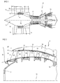
- the figure 1 represents in simplified manner an axial turbomachine. It is in this case a double-flow turbojet engine.
- the turbojet engine 2 comprises a first compression level, called a low-pressure compressor 4, a second compression level, called a high-pressure compressor 6, a combustion chamber 8 and one or more levels of turbines 10.
- the mechanical power the turbine 10 transmitted via the central shaft to the rotor 12 sets in motion the two compressors 4 and 6.
- Reducing means can increase the speed of rotation transmitted to the compressors.
- the different turbine stages can each be connected to the compressor stages via concentric shafts.
- the latter comprise several rows of rotor blades associated with rows of stator vanes. The rotation of the rotor about its axis of rotation 14 thus makes it possible to generate an air flow and to compress it progressively until it reaches the combustion chamber 8.
- a commonly designated fan inlet fan 16 is coupled to the rotor 12 and generates a flow of air which is divided into a primary flow 18 passing through the various levels mentioned above of the turbomachine, and a secondary flow 20 passing through an annular duct (partially shown) along the machine to then join the primary flow at the turbine outlet.
- the primary 18 and secondary 20 streams are annular flows, they are channeled by the casings of the turbomachine.
- the figure 2 is a sectional view of a compressor of an axial turbomachine 2 such as that of the figure 1 .
- the compressor may be a low-pressure compressor 4.
- the rotor 12 comprises several rows of rotor blades 24, in occurrence three.
- the compressor comprises a plurality of rectifiers, in this case four, which each contain a row of stator vanes 26.
- the rectifiers are each associated with a row of rotor vanes for rectifying the air flow, so as to convert the speed of the flow under pressure.
- the compressor comprises at least one housing 28.
- the housing 28 may have a generally annular shape with a profile of revolution about the axis of rotation 14 of the turbomachine. It can be an outer casing and can be made of composite materials. It can be essentially flat.
- the annular casing 28 may comprise fixing flanges 30, for example annular fixing flanges for fastening the separation spout 22 and / or for attaching to an intermediate fan casing 32 of the turbomachine.
- the annular flanges 30 may include attachment holes (not shown) to allow bolt or lockbolt attachment.
- the annular composite casing 28 may comprise a generally circular or arcuate wall, the edges of which may be delimited by the flanges 30.
- the wall 34 may have an ogival shape, with a variation of radius along the axis 14. This evolution of the radius can be reversed.
- the wall 34 has an inner surface with a double curvature, one of the curvatures being in an axial plane, the other curvature being in a radial plane. It is understood that the radial plane is perpendicular to the axis 14, the axial plane extends axially and radially.
- the wall 34 may have annular blade attachment surfaces and / or a series of fixing orifices (not shown) arranged in annular rows for fixing the stator vanes 26.
- the fixing orifices may be provided with inserts (not shown) for reinforcing the composite material of the annular housing 28.
- the inserts may be integrated in the thickness of the wall 34 or flanges 30.
- the annular casing 28 can also be a support for annular layers of abradable material 36 which are arranged against the wall 34 and which are intended to seal with the outer ends of the rotor blades 24.
- the annular fixing surfaces blades and the abradable layers 36 can form an alternation.
- the annular housing 28 may comprise a metallic material and / or a composite material, for example with an organic matrix and carbon fibers.
- the annular housing 28 may comprise a main fibrous reinforcement and an auxiliary fibrous reinforcement.
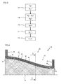
- the figure 3 represents a diagram of the manufacturing process of the composite annular housing.
- the first step 107 may comprise a step of providing or producing an auxiliary fibrous reinforcement. It can be performed several times so as to have an auxiliary reinforcement in each re-entrant edge or corner of the mold. Optionally, it may consist of placing an auxiliary reinforcement forming a loop along the contour of the annular portion.
- the auxiliary reinforcement can go along two axial flanges and two annular flanges.
- the second step 108 may comprise a step of providing or producing a main fibrous reinforcement.
- the reinforcements may be made before the first step of the process.
- the main reinforcement can be made directly from the mold by stacking fibrous folds or by stacking fibrous folds on an external preforming support. Each fold can be woven so as to present in advance the shape that it must occupy when it is arranged in the mold. The folds can be held together by sewing them, pasting them punctually.
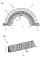
- the figure 4 represents a section of the main fibrous reinforcement 38 of the housing.
- the present teaching can be applied to any casing of the turbomachine.
- the main fiber reinforcement 38 may have a symmetry of revolution with a profile of revolution relative to the axis 14. It may be flat. It may comprise a fibrous preform 40, which has been shaped so as to rough out the shape of the composite annular housing.
- the preform 40 may have a circular partition 42, or an arc of a circle, intended to reinforce the wall of the annular housing, and at least one, preferably two annular fixing flanges 44 which extend radially and which are intended to reinforce the flanges. annular ring seals.
- the preform 40 may comprise a stack or winding of different fibrous sheets 46 or fibrous folds 46, which may extend over the partition 42, and on at least one or more fastening flanges 44. Each fold 46 may extend over an axial fraction of the partition 42. Thus, the number of folds 46 can vary axially. The number of folds can increase downstream. At least one fold 46 may be added to reinforce the junction between the partition 42 and one of the flanges 44.
- the preform 40 may comprise a layer with a fibrous mat which has, according to its thickness, several levels of fibers, for example at least two preferably at least four, more preferably at least ten fiber levels.
- the plies 46 may comprise carbon fibers, and / or graphite fibers, and / or glass fibers.
- the preform may comprise several types of folds.
- the preform may comprise a central layer with folds made of carbon fibers, and at least one fold with glass fibers on the surface, possibly to avoid galvanic corrosion.
- the folds 46 may be nonwoven folds or woven folds, the latter may comprise fibers and / or fiber bundles woven in two directions, for example perpendicular. Each bundle of fibers can have several fibers according to its section. Optionally, a fibrous fold has three directions of weaving.
- the preform 40 may comprise at least five plies 46, preferably at least twelve plies 46, more preferably at least twenty plies 46 depending on its thickness.
- the folds 46 can form a sharp angle at the junction between the partition 42 on the radially outer side of the preform 40. Inside, under each annular flange 44, the preform can form an annular round 50 or elbow which results from the winding folds on the sharp angle.
- the figure 5 represents a section of the main fibrous reinforcement 38 of the composite annular casing along the axis 5-5 traced on the figure 4-4 .
- the annular housing may describe a circle. It can be an annular half-casing which describes a semicircle, or an annular annular casing segment which describes a fraction of a circle; such as a quarter, a sixth, or an eighth of a circle.
- the annular housing can be divided into one or more planes which extend along the axis of rotation 14.
- the half-housings or the housing segments they are provided with axial fixing flanges intended to be fixed to each other, and can form a smooth circle without a step. Therefore, the partition, and the wall may be half-tubes, and extend over a semicircle, or be fractions of a circle. The assembly of half-casings or crankcase fractions makes it possible to describe a closed circle.
- the main reinforcement 38 of the annular housing may also describe a semicircle so as to strengthen the crankcase.
- the main reinforcement may have axial attachment flanges 52, which extend radially and which may follow a sinusoid.
- the main reinforcement 38 can be made by a successive stack of fibrous folds 46, axial roundings 54 can appear at the edge of the wall, at the axial junction with the axial flanges, all along the axial flanges 52.
- the figure 6 represents a section of the auxiliary fibrous reinforcement 56 of the housing.
- the auxiliary fibrous reinforcement 56 may comprise a core 58.
- the core 58 may be a fiber bundle 60, possibly woven or braided dimensionally. Its fibers 60 may describe spirals along the ridge.
- the fibers 60 and / or fiber bundles of the core 58 may be of the same nature as the fibers of the preform. By the same nature we can hear the same material, and / or the same length and / or the same diameter.
- the auxiliary reinforcement 56 may comprise portions extending radially or axially the core 58.
- the core 58 may have an elongation and a cross section in a plane perpendicular to its elongation. Its cross section may be generally a polygon, such as a triangular, possibly rectangle and / or isosceles.
- the maximum height H of the triangle of the profile of the core 58 is substantially equal to the thickness of one of the flanges and / or the thickness of the wall of the first preform. Said height is measured radially when the auxiliary reinforcement 56 is placed in the mold, it can be between 60% and 140%, preferably between 90% and 110% of the thickness of one of the flanges and / or the thickness of the wall of the first preform.
- the core 58 has a substantially constant fiber density.
- the fibers 60 of the core 58 may be mainly oriented parallel to the elongation of the auxiliary reinforcement 58. Each of their portions forms an angle less than 45 ° relative to the elongation of the auxiliary reinforcement, preferably less than 20 °.
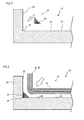
- the figure 7 represents a first step of the method of manufacturing the composite annular casing according to the invention.
- a mold portion is shown in section along a plane passing through an axis corresponding to the axis 14.
- the method employs an injection mold with a first mold 62.
- the first step comprises placing the auxiliary reinforcement 56 inside the first mold 62, with its core against a molding surface 64.
- the mold 62 can be a mold for producing an annular housing, a segment of the annular housing or a half-shell. It may have molding surfaces generated by a revolution profile.
- the mold may have a generally tubular annular molding surface 66 which is the conjugate of the inner surface of the mold. annular housing. Although the tubular molding surface shown here is straight, it is obvious that in practice it may have any curved shape for producing an axial flange or an annular flange.
- the mold 62 may also have a radially extending molding surface 68, which is the conjugate of a fastening surface of one of the flanges.
- the tubular surface 66 and the radial surface 68 form a corner 70 or recess 70 at their junction. In order to fill this corner 70, the auxiliary reinforcement 56 is applied thereto.
- auxiliary reinforcement 56 is shown, it is conceivable to apply others, for example at an opposite flange, or at the level of steps forms.
- the figure 8 represents a second step of the method of manufacturing the composite annular casing according to the invention.
- the second step comprises the establishment of the main fibrous reinforcement 38, so that the latter covers the tubular surface 66 and the radial surface 68 of the mold 62, as well as the auxiliary reinforcement 56, and any other auxiliary reinforcements.
- the main reinforcement 38 comes into contact with the core 58 of the auxiliary reinforcement 56 at a contact surface with a generally straight profile.
- the figure 9 represents the main reinforcement 38 and the auxiliary reinforcement 56 when they are both in place in the mold 62.
- These reinforcements may fit on the majority, preferably on at least 80%, more preferably on the entire thickness of the flange 44 or 52 and / or on the majority, preferably on at least 80%, more preferably on the all the thickness of the partition 42 of the main reinforcement 38.
- they marry they compress each other, the long side of the triangle is curved, and the rounded (50, 54) at the junction between the flange and the partition 42 of the main reinforcement crushes, flattens.
- the reinforcements can marry the majority, preferably the entire radial height of the core of the auxiliary reinforcement.
- fibers of the two preforms can pass through said interface 71, and be intercalated at the same level. They can be imbedded which improves the coherence in combination with the matrix.
- the figure 10 represents a third step of the method of manufacturing the composite annular casing according to the invention.
- the third step of the method comprises closing the injection mold, the latter comprising at least a second mold 72 or against mold 72 which is applied against the main reinforcement 38 and the compact.
- Counter mold 72 may be a male mold.
- Counter-mold 72 can reduce the thickness of the partition and / or the thickness of the flange (44, 52) of the main reinforcement 38.
- the mold 62 and the counter-mold 72 define between them a molding cavity reproducing essentially the shape of the annular housing.
- the core 58 can be compacted again.
- the effect of the closing of the mold can make it possible to reduce the thicknesses of the preforms by at least 5%, preferably at least 20%.
- the figure 11 represents a fourth step of the method of manufacturing the composite annular casing according to the invention.
- the fourth step comprises injecting a resin 74, in particular an organic resin, into the injection mold.
- the resin may be a thermoplastic resin such as epoxy, polyetherimide (PEI), polyetheretherketone (PEEK).
- the injection may consist in impregnating the preforms, according to a process of the RTM (acronym for Resin Transfer Molding) type.
- the method may include an injection of a charged resin.
- the injection may be assisted by aspiration.
- the mold can be maintained for a period of at least one hour at a temperature above 50 ° C, preferably above 120 ° C. Following these steps, the resin polymerizes and hardens and can adhere to the reinforcements; thus forming a solid body.
- the figure 12 represents a fifth step of the method of manufacturing the composite annular casing 28 according to the invention.
- the fifth step comprises demolding the composite annular casing 28.
- the counter mold is removed from the mold 62, then a demolding force is applied on the housing to extract it from the mold.
- the housing 28 resulting from molding can be machined. It can be perforated at the flanges 30 to make fixing holes, and / or at the wall 34 to allow the mounting of blades.
- the axial and / or annular flanges may be cut to remove the heterogeneous ends, specially added to improve the quality of the finished flanges.
- the matrix links the main reinforcement 38 and the auxiliary reinforcement 56. It has a continuity of material at the interface 71 between the reinforcements (38; 56), which allows them to be secured. This configuration promotes the anchoring of the reinforcements.
- the core of the auxiliary reinforcement 56 comprises fibers which extend radially over at least 10%, preferably on at least all, more preferably on at least twice the thickness of the wall 34. These fibers improve the radial compressive strength from the ridge and allow the ridge to form a block. These fibers can extend from a stop 76 of the casing 28 to the main reinforcement 38.
- the main fibrous reinforcement 38 extends continuously along the wall 38 and the flange 30 forming a bent portion and generally rounded at the edge.
- the core 58 extends along the edge 76 so as to fill the volume between the edge and the bent portion of the main reinforcement 38.
- the interface 71 may have a generally curved profile and substantially flattened.
- the reinforcements (38 and 56) can be configured so that the housing 28 has a continuity and homogeneity of fiber density in the junction 80 between the flange 30 and the wall 34 and / or along the surface of the junction 80. This homogeneity improves the mechanical strength and the endurance of the casing 28 which can be subjected to vibrations, chemical attacks at a temperature above 170 ° C during the operation of the turbomachine.
- the general radius of the rounded interface and / or the thickness of the wall is / are greater than 1%, preferably greater than 2%, more preferably greater than 4%, possibly greater than 6% of the radius of the sharp edge.
- the casing 28 has a sharp edge 76 forming a salient angle.
- This edge can be integrated in the turbomachine, without requiring additional machining.
- the stop 76 may be generally perpendicular, which makes it possible to achieve a smooth junction when it is brought into alignment with a corresponding edge.
- the union of the two edges makes it possible to produce a guiding surface of a flow without any projection which would be detrimental to the smooth flow of the flow.
- This meeting can also form a mounting area without asperity, for example to come and support a platform dawn for its positioning and fixing.
Landscapes
- Engineering & Computer Science (AREA)
- Mechanical Engineering (AREA)
- General Engineering & Computer Science (AREA)
- Chemical & Material Sciences (AREA)
- Composite Materials (AREA)
- Materials Engineering (AREA)
- Architecture (AREA)
- Civil Engineering (AREA)
- Structural Engineering (AREA)
- Manufacturing & Machinery (AREA)
- Structures Of Non-Positive Displacement Pumps (AREA)
Abstract
Description
- L'invention a trait à un carter annulaire externe composite de turbomachine axiale. Plus précisément, l'invention a trait à un carter annulaire composite de turbomachine axiale présentant une paroi circulaire, une bride annulaire radiale une arête vive à leur jonction ; le composite comprenant une préforme fibreuse. L'invention a également trait à une turbomachine axiale comprenant un carter annulaire composite. L'invention a également trait à un procédé de fabrication d'un carter annulaire composite de turbomachine axiale.
- Dans le but d'alléger une turbomachine, certains de ses éléments conventionnellement produits en métal peuvent l'être en un matériau composite. Des éléments structurants tels des supports, des carters peuvent être produits en un matériau composite. En particulier, un carter externe de compresseur, notamment basse pression, peut être produit en un matériau composite.
- Un tel carter présente généralement une portion cylindrique qui supporte des rangées annulaires d'aubes, et des brides annulaires de fixation qui s'étendent radialement. Les brides permettent le montage du carter de compresseur sur un carter intermédiaire de soufflante, et la fixation d'un bec annulaire de séparation. La surface interne du carter permet de guider le flux annulaire le long du compresseur, et doit à cet effet présenter une surface lisse ; sans ressauts. Cette contrainte impose de réaliser des arêtes vives au niveau des brides de fixations.
- Un carter externe composite de compresseur peut être réalisé à partir d'une préforme densifiée par une matrice. La préforme peut être formée d'un empilement de feuilles fibreuses empilées les unes sur les autres, les feuilles s'étendant à la fois sur la portion cylindrique et sur les brides de fixation. Une fois mise en forme, la préforme est disposée dans un moule d'injection présentant des arêtes pour reproduire la forme voulue du carter. Or, la préforme empilée forme un arrondi au niveau de l'arête du moule et laisse subsister une espace vide à cet endroit. Lors de l'injection, l'espace est rempli par la résine sans être renforcé par des fibres. Par conséquent, le carter composite présente une faiblesse à cet endroit.
- Il est connu du document
GB 2486231 A - Le document
EP 1 900 502 A1 divulgue un composant composite annulaire de turbomachine. Le composant présente un corps annulaire et des brides annulaires aux extrémités, et des arêtes annulaires vives à l'intérieur des brides. Le composant composite comprend plusieurs renforts fibreux dont l'un est effiloché au niveau arrêtes de sorte à y répartir les fibres dans les jonctions entre les brides et le corps annulaire. L'enseignement de ce document permet de répartir des fibres dans les jonctions, mais provoque une hétérogénéité de densité de fibres. Cette hétérogénéité réduit la résistance mécanique du composant composite, et en particulier face à un effort de flexion appliqué à une bride. - L'invention a pour objectif de résoudre au moins un des problèmes posés par l'art antérieur. L'invention a également pour objectif de renforcer une jonction annulaire entre une bride de fixation et une paroi circulaire d'un carter annulaire externe composite de turbomachine. L'invention a également pour objectif de renforcer au plus près une arête vive sous une bride annulaire du carter annulaire externe composite de turbomachine.
- L'invention a trait à un carter annulaire composite de turbomachine, notamment de compresseur basse pression, comportant une paroi généralement circulaire ou en arc de cercle ; une bride de fixation s'étendant radialement depuis un bord de la paroi, formant avec ladite paroi une arête ; un renfort fibreux principal s'étendant de manière continue le long de la paroi et de la bride en formant une portion coudée et arrondie au niveau de l'arête ; et un renfort fibreux auxiliaire s'étendant le long de l'arête; une matrice ; remarquable en ce que le renfort auxiliaire comprend un noyau s'étendant le long de l'arête de manière à combler le volume entre l'arête et la portion coudée du renfort principal.
- Selon un mode avantageux de l'invention, le noyau du renfort auxiliaire comprend un toron préférentiellement tressé ou tissé, éventuellement de manière tridimensionnelle.
- Selon un mode avantageux de l'invention, la section transversale du noyau du renfort auxiliaire présente un profil généralement en triangle, éventuellement en triangle rectangle dont l'angle droit est disposé au niveau de l'arête vive.
- Selon un mode avantageux de l'invention, le renfort principal et le renfort auxiliaire sont essentiellement en contact sur toute l'épaisseur radiale de la paroi et/ou sur toute l'épaisseur axiale de la bride de fixation.
- Selon un mode avantageux de l'invention, le noyau du renfort auxiliaire comprend des fibres qui s'étendent radialement depuis l'arête jusqu'au renfort principal, préférentiellement le noyau du renfort auxiliaire présente une densité en fibres homogène perpendiculairement à son allongement.
- Selon un mode avantageux de l'invention, la bride de fixation est une bride annulaire de fixation et/ou une bride axiale de fixation, préférentiellement le carter annulaire est un demi-carter annulaire s'étendant sur un demi-cercle qui comprend des brides axiales disposées latéralement sur la portion cylindrique et des brides annulaires opposées disposées aux extrémités axiales de la portion cylindrique.
- Selon un mode avantageux de l'invention, les fibres du noyau du renfort auxiliaire s'étendent principalement parallèlement à l'arrête, préférentiellement chaque portion de fibres du renfort auxiliaire (56) est inclinée par rapport à l'arête d'un angle inférieur à 40°, plus préférentiellement inférieur à 20°.
- Selon un mode avantageux de l'invention, le noyau du renfort auxiliaire comprend des fibres de même nature que le renfort principal, préférentiellement les fibres du renfort principal et du noyau du renfort auxiliaire sont de même longueur et/ou de même diamètre.
- Selon un mode avantageux de l'invention, les fibres du renfort principal et du noyau du renfort auxiliaire sont imbriquées à l'interface entre le renfort principal et le renfort auxiliaire, préférentiellement les fibres des renforts sont agencées en faisceaux de fibres qui sont imbriqués au travers de l'interface.
- Selon un mode avantageux de l'invention, le renfort principal et le noyau du renfort auxiliaire présentent chacun une densité de fibres homogène, préférentiellement le rapport des densités de fibres des renforts est compris entre 0,5 et 1,50 ; préférentiellement compris entre 0,80 et 1,20 ; plus préférentiellement compris entre 0,95 et 1,05.
- Selon un mode avantageux de l'invention, la section du noyau est symétrique.
- Selon un mode avantageux de l'invention, chaque portion de fibre du noyau est inclinée par rapport à l'axe d'allongement du carter d'un angle compris entre 50° et 130°, préférentiellement compris entre 60° et 120°, plus préférentiellement compris entre 75° et 105°.
- Selon un mode avantageux de l'invention, le noyau épouse le renfort principal sur la majorité, préférentiellement sur toute la hauteur radiale du noyau.
- Selon un mode avantageux de l'invention, le carter présente une continuité de matière entre la bride de fixation et la paroi.
- Selon un mode avantageux de l'invention, l'enveloppe du noyau délimite un espace qui occupe au moins 15%, préférentiellement au moins 25 %, plus préférentiellement au moins 35% de la jonction entre la bride et la paroi du carter annulaire.
- Selon un mode avantageux de l'invention, la matrice et le noyau forment l'arrête vive.
- Selon un mode avantageux de l'invention, le carter comprend une bride s'étendant perpendiculairement à la paroi.
- L'invention a également trait à une pièce composite, notamment de turbomachine, comportant : une paroi structurante, une bride de fixation s'étendant perpendiculairement depuis un bord de la paroi structurante et formant avec ladite paroi une arête, une matrice, un renfort fibreux principal s'étendant de manière continue le long de la paroi et de la bride en formant une portion coudée et arrondie au niveau de l'arête, et un renfort fibreux auxiliaire s'étendant le long de l'arête; remarquable en ce que le renfort auxiliaire comprend un noyau avec des fibres s'étendant radialement sur la majorité, préférentiellement sur la totalité de l'épaisseur de la paroi structurante, et/ou le noyau s'étend le long de l'arête de manière à combler le volume entre l'arête et la portion coudée du renfort principal.
- L'invention a également trait à une turbomachine comprenant un carter annulaire composite, remarquable en ce que le carter annulaire composite est conforme à l'invention, préférentiellement la matrice est une matrice organique à base de polyétherimide, d'époxy, ou de polyétheréthercétone ; le renfort principal (38) est une préforme fibreuse comprenant un empilement de plis fibreux (46) avec des fibres de carbone et des fibres de verres, chaque pli fibreux comprenant des fibres agencées en faisceaux de fibres tissés selon au moins deux directions.
- Selon un mode avantageux de l'invention, la turbomachine comprend un carter intermédiaire de soufflante, un compresseur basse pression avec des rangées annulaires d'aubes statoriques et un bec de séparation, le carter annulaire comprenant une bride annulaire de fixation à chaque extrémité axiale, dont une bride amont et une bride aval, le carter annulaire présentant une réduction de rayon vers l'aval, préférentiellement le carter annulaire est une structure principale externe du compresseur sur laquelle sont fixées les rangées d'aubes, le bec de séparation via la bride amont, le carter intermédiaire de soufflante via la bride aval, le carter annulaire comprenant en outre une alternance de couches annulaires de matériau abradable et de surfaces annulaires de fixation d'aubes, le carter annulaire est formé de demi-coquilles séparées par un plan s'étendant axialement.
- L'invention a également trait à un procédé de fabrication d'un carter annulaire composite de turbomachine qui comprend une paroi de profil généralement circulaire ou en arc de cercle, une bride de fixation s'étendant radialement depuis un bord de la paroi et formant avec la paroi une arête, remarquable en ce que le procédé comprend les étapes suivantes : (a) mise en place d'un renfort auxiliaire dans un coin d'une surface de moulage d'un moule d'injection, ledit coin formant l'arête; (b) mise en place d'un renfort principal contre la surface de moulage en épousant le renfort auxiliaire au niveau du coin; (c) fermeture du moule d'injection; (d) injection d'une résine et polymérisation de la résine ; (e) démoulage du carter.
- Selon un mode avantageux de l'invention, avant l'étape (b) de mise en place d'un renfort principal, ledit renfort est produit avec un arrondi destinée à venir en contact d'une surface de contact du renfort auxiliaire, préférentiellement à l'issue de l'étape (b) l'arrondi du renfort principal s'aplatit et la surface de contact du renfort auxiliaire s'incurve.
- Selon un mode avantageux de l'invention, lors de l'étape (c) fermeture du moule d'injection, le renfort principal est compacté et/ou le renfort principal et le noyau se compactent mutuellement.
- Selon un mode avantageux de l'invention, au moment de la fermeture du moule, le noyau épouse sur toute sa hauteur radiale la surface du moule qui forme la bride.
- L'invention permet de renforcer une arête vive de carter de turbomachine. La densité en fibre y est homogène, ce qui optimise la résistance mécanique. La répartition des fibres de part et d'autre de l'arête peut être symétrique, ce qui améliore les propriétés mécaniques. Le procédé permet de réaliser une arête vive avec des côtes précises et une arête affutée, sans nécessiter d'usinage complémentaire.
-
- La
figure 1 représente une turbomachine axiale selon l'invention. - La
figure 2 est un schéma d'un compresseur de turbomachine selon l'invention. - La
figure 3 est un diagramme représentant le procédé de fabrication d'un carter selon l'invention. - La
figure 4 schématise un renfort fibreux principal du carter selon l'invention. - La
figure 5 illustre une coupe du renfort fibreux principal du carter selon l'invention suivant l'axe 5-5 tracé sur lafigure 4 . - La
figure 6 schématise un renfort fibreux auxiliaire du carter selon l'invention. - La
figure 7 représente l'étape du procédé de mise en place du renfort fibreux auxiliaire dans le moule selon l'invention. - La
figure 8 représente l'étape du procédé de mise en place du renfort fibreux principal dans le moule selon l'invention. - La
figure 9 représente un état intermédiaire du procédé où les renforts sont disposés dans le moule selon l'invention. - La
figure 10 représente l'étape du procédé de fermeture du moule selon l'invention. - La
figure 11 représente l'étape du procédé d'injection d'une résine dans le moule selon l'invention. - La
figure 12 représente l'étape du procédé de démoulage du carter selon l'invention. - Dans la description qui va suivre, les termes intérieur ou interne et extérieur ou externe renvoient à un positionnement par rapport à l'axe de rotation d'une turbomachine axiale.
- Dans la description qui va suivre, les termes intérieur ou interne et extérieur ou externe renvoient à un positionnement par rapport à l'axe de rotation d'une turbomachine axiale.
- La
figure 1 représente de manière simplifiée une turbomachine axiale. Il s'agit dans ce cas précis d'un turboréacteur double-flux. Le turboréacteur 2 comprend un premier niveau de compression, dit compresseur basse-pression 4, un deuxième niveau de compression, dit compresseur haute-pression 6, une chambre de combustion 8 et un ou plusieurs niveaux de turbines 10. En fonctionnement, la puissance mécanique de la turbine 10 transmise via l'arbre central jusqu'au rotor 12 met en mouvement les deux compresseurs 4 et 6. Des moyens de démultiplication peuvent augmenter la vitesse de rotation transmise aux compresseurs. Ou encore, les différents étages de turbines peuvent chacun être reliés aux étages de compresseur via des arbres concentriques. Ces derniers comportent plusieurs rangées d'aubes de rotor associées à des rangées d'aubes de stators. La rotation du rotor autour de son axe de rotation 14 permet ainsi de générer un débit d'air et de comprimer progressivement ce dernier jusqu'à l'entrée de la chambre de combustion 8. - Un ventilateur d'entrée communément désigné fan 16 est couplé au rotor 12 et génère un flux d'air qui se divise en un flux primaire 18 traversant les différents niveaux sus mentionnés de la turbomachine, et un flux secondaire 20 traversant un conduit annulaire (partiellement représenté) le long de la machine pour ensuite rejoindre le flux primaire en sortie de turbine. Les flux primaire 18 et secondaire 20 sont des flux annulaires, ils sont canalisés par les carter de la turbomachine.
- La
figure 2 est une vue en coupe d'un compresseur d'une turbomachine axiale 2 telle que celle de lafigure 1 . Le compresseur peut être un compresseur basse-pression 4. On peut y observer une partie du fan 16 et le bec de séparation 22 du flux primaire 18 et du flux secondaire 20. Le rotor 12 comprend plusieurs rangées d'aubes rotoriques 24, en l'occurrence trois. - Le compresseur comprend plusieurs redresseurs, en l'occurrence quatre, qui contiennent chacun une rangée d'aubes statoriques 26. Les redresseurs sont chacun associé à une rangée d'aubes rotoriques pour redresser le flux d'air, de sorte à convertir la vitesse du flux en pression.
- Le compresseur comprend au moins un carter 28. Le carter 28 peut présenter une forme généralement annulaire avec un profil de révolution autour de l'axe de rotation 14 de la turbomachine. Il peut être un carter externe et peut être réalisé en matériaux composites. Il peut être essentiellement plat. Le carter annulaire 28 peut comprendre des brides de fixation 30, par exemple des brides annulaires de fixation pour la fixation du bec de séparation 22 et/ou pour se fixer à un carter intermédiaire de soufflante 32 de la turbomachine. Les brides annulaires 30 peuvent comprendre des orifices de fixation (non représentés) pour permettre une fixation par boulons, ou par lockbolts.
- La carter annulaire composite 28 peut comprendre une paroi généralement 34 circulaire ou en arc de cercle, dont les bords peuvent être délimités par les brides 30. La paroi 34 peut présenter une forme d'ogive, avec une variation de rayon le long de l'axe 14. Cette évolution du rayon peut s'inverser. La paroi 34 présente une surface intérieure avec une double courbure, l'une des courbures étant selon un plan axial, l'autre courbure étant selon un plan radial. Il est entendu que le plan radial est perpendiculaire à l'axe 14, le plan axial s'étend axialement et radialement.
- La paroi 34 peut présenter des surfaces annulaires de fixations d'aubes et/ou des séries d'orifices de fixation (non représentés) disposées en rangées annulaires pour la fixation des aubes statoriques 26. Les orifices de fixation peuvent être munis d'inserts (non représentés) pour renforcer le matériau composite du carter annulaire 28. Les inserts peuvent être intégrés dans l'épaisseur de la paroi 34 ou des brides 30.
- Le carter annulaire 28 peut également être un support pour des couches annulaires de matériau abradable 36 qui sont disposées contre la paroi 34 et qui sont destinées à assurer une étanchéité avec les extrémités externes des aubes rotoriques 24. Les surfaces annulaires de fixations d'aubes et les couches d'abradable 36 peuvent former une alternance. Le carter annulaire 28 peut comprendre un matériau métallique et/ou un matériau composite, par exemple avec une matrice organique et des fibres de carbone. Le carter annulaire 28 peut comprendre un renfort fibreux principal et un renfort fibreux auxiliaire.
- La
figure 3 représente un diagramme du procédé de fabrication du carter annulaire composite. - Le procédé peut comprendre la succession, éventuellement dans cet ordre, des étapes suivantes:
- (a) une première étape de mise en place du renfort fibreux auxiliaire (107) ;
- (b) une deuxième étape de mise en place du renfort fibreux principal (108) ;
- (c) une troisième étape de fermeture du moule d'injection (110) ;
- (d) une quatrième étape d'injection et de polymérisation (111) ;
- (e) une cinquième étape de démoulage et éventuellement d'usinage (112).
- La première étape 107 peut comprendre une étape de fourniture ou réalisation d'un renfort fibreux auxiliaire. Elle peut être réalisée plusieurs fois de sorte à disposer un renfort auxiliaire dans chaque arête rentrante ou coin du moule. Eventuellement, elle peut consister à placer un renfort auxiliaire formant une boucle longeant le contour de la portion annulaire. Par exemple, le renfort auxiliaire peut longer deux brides axiales et deux brides annulaires.
- La deuxième étape 108 peut comprendre une étape de fourniture ou réalisation d'un renfort fibreux principal. Suivant une alternative de l'invention, les renforts peuvent être réalisés avant la première étape du procédé. Le renfort principal peut être réalisé à même le moule par empilement de plis fibreux ou par empilement de plis fibreux sur un support de préformage externe. Chaque pli peut être tissé de sorte à présenter à l'avance la forme qu'il doit occuper lorsqu'il est disposé dans le moule. Les plis peuvent être maintenus les uns aux autres en les cousant, en les collant ponctuellement.
- Les étapes présentées ci-dessus ainsi que les éléments employés sont détaillés d'avantage dans les paragraphes suivants.
- La
figure 4 représente une coupe du renfort fibreux principal 38 du carter. Le présent enseignement pouvant être appliqué à tout carter de la turbomachine. - Le renfort fibreux principal 38 peut présenter une symétrie de révolution avec un profil de révolution par rapport à l'axe 14. Il peut être plat. Il peut comprendre une préforme fibreuse 40, qui a été formée de sorte à ébaucher la forme du carter annulaire composite. La préforme 40 peut présenter une cloison circulaire 42, ou en arc de cercle, destinée à renforcer la paroi du carter annulaire, et au moins une, préférentiellement deux brides annulaires de fixation 44 qui s'étendent radialement et qui sont destinées à renforcer les brides annulaires du carter annulaire.
- La préforme 40 peut comprendre un empilement ou un enroulement de différentes feuilles fibreuses 46 ou plis fibreux 46, qui peuvent s'étendre sur la cloison 42, et sur au moins une ou plusieurs brides de fixation 44. Chaque pli 46 peut s'étendre sur une fraction axiale de la cloison 42. Ainsi, le nombre de plis 46 peut varier axialement. Le nombre de plis peut augmenter vers l'aval. Au moins un pli 46 peut être ajouté pour renforcer la jonction entre la cloison 42 et une des brides 44. La préforme 40 peut comprendre une couche avec un matelas fibreux qui présente, selon son épaisseur, plusieurs niveaux de fibres, par exemple au moins deux préférentiellement au moins quatre, plus préférentiellement au moins dix niveaux de fibres.
- Les plis 46 peuvent comprendre des fibres de carbone, et/ou des fibres de graphite, et/ou des fibres de verre. Avantageusement, la préforme peut comprendre plusieurs types de plis. Par exemple, la préforme peut comprendre une couche centrale avec des plis en fibres de carbone, et au moins un pli avec des fibres de verre en surface, éventuellement pour éviter une corrosion galvanique.
- Les plis 46 peuvent être des plis non tissés ou des plis tissés, ces derniers peuvent comprendre des fibres et/ou des faisceaux de fibres tissés selon deux directions, par exemple perpendiculaires. Chaque faisceau de fibres peut présenter plusieurs fibres selon sa section. Eventuellement, un pli fibreux présente trois directions de tissage.
- La préforme 40 peut comprendre au moins cinq plis 46, préférentiellement au moins douze plis 46, plus préférentiellement au moins vingt plis 46 selon son épaisseur. Les plis 46 peuvent former un angle vif à la jonction entre la cloison 42 du côté radialement extérieur de la préforme 40. A l'intérieur, sous chaque bride annulaire 44, la préforme peut former un arrondi annulaire 50 ou coude qui résulte de l'enroulement des plis sur l'angle vif.
- La
figure 5 représente une coupe du renfort fibreux principal 38 du carter annulaire composite suivant l'axe 5-5 tracé sur lafigure 4-4 . - Le carter annulaire peut décrire un cercle. Il peut être un demi-carter annulaire qui décrit un demi-cercle, ou un segment annulaire de carter annulaire qui décrit une fraction de cercle ; tel un quart, un sixième, ou un huitième de cercle.
- Le carter annulaire peut être divisé selon un ou plusieurs plans qui s'étendent suivant l'axe de rotation 14. Pour joindre les demi-carters ou les segments de carters, ceux-ci sont munis de brides axiales de fixation destinées à être fixées les unes aux autres, et peuvent former un cercle lisse, sans marche. Par conséquent, la cloison, et la paroi peuvent être des demi-tubes, et s'étendre sur un demi-cercle, ou être des fractions de cercle. L'assemblage de demi-carters ou des fractions de carter permet de décrire un cercle fermé.
- Le renfort principal 38 du carter annulaire peut également décrire un demi-cercle de sorte à renforcer le demi-carter. Le renfort principal peut présenter des brides axiales de fixation 52, qui s'étendent radialement et qui peuvent suivre une sinusoïde. Le renfort principal 38 pouvant être réalisé par un empilement successif de plis fibreux 46, des arrondis axiaux 54 peuvent apparaître au bord de la paroi, à la jonction axiale avec les brides axiales, tout le long axialement des brides axiales 52.
- La
figure 6 représente une coupe du renfort fibreux auxiliaire 56 du carter. - Le renfort fibreux auxiliaire 56 peut comprendre un noyau 58. Le noyau 58 peut être un toron de fibres 60, éventuellement tissé ou tressé tridimensionnellement. Ses fibres 60 peuvent décrire des spirales longeant l'arête. Les fibres 60 et/ou les faisceaux de fibres du noyau 58 peuvent être de même nature que les fibres de la préforme. Par même nature on peut entendre de même matière, et/ou de même longueur et/ou de même diamètre.
- Le renfort auxiliaire 56 peut comprendre des portions prolongeant radialement ou axialement le noyau 58. Le noyau 58 peut présenter un allongement et une section transversale selon un plan perpendiculaire à son allongement. Sa section transversale peut être généralement un polygone, tel un triangule, éventuellement rectangle et/ou isocèle. La hauteur maximale H du triangle du profil du noyau 58 est sensiblement égale à l'épaisseur d'une des brides et/ou de l'épaisseur de la paroi de la première préforme. Ladite hauteur est mesurée radialement lorsque le renfort auxiliaire 56 est disposé dans le moule, elle peut être comprise entre 60% et 140%, préférentiellement entre 90% et 110% de l'épaisseur d'une des brides et/ou de l'épaisseur de la paroi de la première préforme. Le noyau 58 présente une densité en fibre essentiellement constante.
- Les fibres 60 du noyau 58 peuvent être principalement orientées parallèlement à l'allongement du renfort auxiliaire 58. Chacune de leurs portions forme un angle inférieur à 45° par rapport à l'allongement du renfort auxiliaire, préférentiellement inférieur à 20°.
- La
figure 7 représente une première étape du procédé de fabrication du carter annulaire composite selon l'invention. Une portion de moule est représentée en coupe selon un plan passant par un axe qui correspond à l'axe 14. - Le procédé emploie un moule d'injection avec un premier moule 62. La première étape comprend la mise en place du renfort auxiliaire 56 à l'intérieur du premier moule 62, avec son noyau contre une surface de moulage 64. Le moule 62 peut être un moule permettant de réaliser un carter annulaire, un segment du carter annulaire ou une demi-coquille. Il peut présenter des surfaces de moulage générées par un profil de révolution. Le moule peut présenter une surface de moulage annulaire généralement tubulaire 66 qui est la conjuguée de la surface intérieure du carter annulaire. Bien que la surface de moulage tubulaire ici représentée soit droite, il est évident que dans la pratique elle peut présenter toute forme courbe permettant de réaliser une bride axiale ou une bride annulaire.
- Le moule 62 peut également présenter une surface de moulage s'étendant radialement 68, qui est la conjuguée d'une surface de fixation d'une des brides. La surface tubulaire 66 et la surface radiale 68 forment un coin 70 ou angle rentrant 70 à leur jonction. Afin de combler ce coin 70, le renfort auxiliaire 56 y est appliqué.
- Bien qu'un seul renfort auxiliaire 56 soit représenté, il est envisageable d'en appliquer d'autres, par exemple au niveau d'une bride opposée, ou au niveau de formes de marches.
- La
figure 8 représente une deuxième étape du procédé de fabrication du carter annulaire composite selon l'invention. - La deuxième étape comprend la mise en place du renfort fibreux principal 38, de sorte à ce que ce dernier recouvre la surface tubulaire 66 et la surface radiale 68 du moule 62, ainsi que le renfort auxiliaire 56, et d'éventuels autres renforts auxiliaires. Lors de cette étape, le renfort principal 38 rentre en contact du noyau 58 du renfort auxiliaire 56 au niveau d'une surface de contact avec un profil généralement droit.
- La
figure 9 représente le renfort principal 38 et le renfort auxiliaire 56 lorsqu'ils sont tous deux en place dans le moule 62. - Ces renforts peuvent s'épouser sur la majorité, préférentiellement sur au moins 80%, plus préférentiellement sur la totalité de l'épaisseur de la bride 44 ou 52 et/ou sur la majorité, préférentiellement sur au moins 80%, plus préférentiellement sur la totalité de l'épaisseur de la cloison 42 du renfort principal 38. Lorsqu'ils s'épousent, ils se compressent mutuellement, le grand côté du triangle s'incurve, et l'arrondi (50, 54) à la jonction entre la bride et la cloison 42 du renfort principal s'écrase, s'aplatit. Les renforts peuvent s'épouser sur la majorité, préférentiellement la totalité de la hauteur radiale du noyau du renfort auxiliaire.
- A l'interface 71 des préformes, des fibres des deux préformes peuvent traverser ladite interface 71, être intercalés suivant un même niveau. Elles peuvent s'imbriquer ce qui améliore la cohérence en combinaison avec la matrice.
- La
figure 10 représente une troisième étape du procédé de fabrication du carter annulaire composite selon l'invention. - La troisième étape du procédé comprend la fermeture du moule d'injection, ce dernier comprenant au moins un deuxième moule 72 ou contre-moule 72 qui est appliqué contre le renfort principal 38 et le compacte. Le contre-moule 72 peut être un moule male. Le contre-moule 72 peut réduire l'épaisseur de la cloison et/ou l'épaisseur de la bride (44, 52) du renfort principal 38. Le moule 62 et le contre-moule 72 définissent entre eux une cavité de moulage reproduisant essentiellement la forme du carter annulaire. Lors de cette étape, le noyau 58 peut être à nouveau compacté. L'effet de la fermeture du moule peut permettre de réduire les épaisseurs des préformes d'au moins 5%, préférentiellement au moins 20%.
- La
figure 11 représente une quatrième étape du procédé de fabrication du carter annulaire composite selon l'invention. - La quatrième étape comprend l'injection d'une résine 74, notamment une résine organique, dans le moule d'injection. La résine peut être une résine thermoplastique telle de l'époxy, du polyétherimide (PEI), du polyétheréthercétone (PEEK). L'injection peut consister à imprégner les préformes, selon un procédé du type RTM (acronyme anglais pour Resin Transfer Molding). Le procédé peut comprendre une injection d'une résine chargée. Eventuellement, l'injection peut être assistée d'une aspiration.
- Suite à l'injection, le moule peut être maintenu pendant une période d'au moins une heure à une température supérieure à 50°C, préférentiellement supérieure à 120°C. Suite à ces étapes, la résine polymérise et durcit et peut adhérer aux renforts ; formant ainsi un corps solide.
- La
figure 12 représente une cinquième étape du procédé de fabrication du carter annulaire composite 28 selon l'invention. - La cinquième étape comprend le démoulage du carter annulaire composite 28. Dans un premier temps, le contre moule est ôté du moule 62, puis un effort de démoulage est appliqué sur le carter pour l'extraire du moule.
- Le carter 28 issu de moulage peut être usiné. Il peut être perforé au niveau des brides 30 pour réaliser des orifices de fixation, et/ou au niveau de la paroi 34 pour permettre le montage d'aubes. Eventuellement, les brides axiales et/ou annulaires peuvent être découpées pour enlever les extrémités hétérogènes, spécialement ajoutées pour améliorer la qualité des brides finies.
- Une fois polymérisée, la matrice lie le renfort principal 38 et le renfort auxiliaire 56. Elle présente une continuité de matière à l'interface 71 entre les renforts (38 ; 56), ce qui permet de les solidariser. Cette configuration favorise l'ancrage des renforts. Le noyau du renfort auxiliaire 56 comprend des fibres qui s'étendent radialement, sur au moins 10 %, préférentiellement sur au moins toute, plus préférentiellement sur au moins deux fois l'épaisseur de la paroi 34. Ces fibres améliorent la résistance en compression radiale de l'arête et permettent à l'arrête de former un bloc. Ces fibres peuvent s'étendre depuis une arrête 76 du carter 28 jusqu'au renfort principal 38.
- Le renfort fibreux principal 38 s'étend de manière continue le long de la paroi 38 et de la bride 30 en formant une portion coudée et généralement arrondie au niveau de l'arête. Le noyau 58 s'étend le long de l'arête 76 de manière à combler le volume entre l'arête et la portion coudée du renfort principal 38. L'interface 71 peut présenter un profil généralement courbe et sensiblement aplati. Les renforts (38 et 56) peuvent être configurés de sorte à ce que le carter 28 présente une continuité et une homogénéité de densité de fibre dans la jonction 80 entre la bride 30 et la paroi 34 et/ou le long des surface de la jonction 80. Cette homogénéité améliore la résistance mécanique et l'endurance du carter 28 qui peut être soumis à des vibrations, à des attaques chimiques à une température supérieure à 170 °C pendant le fonctionnement de la turbomachine.
- Le rayon général de l'interface arrondie et/ou l'épaisseur de la paroi est/sont supérieur(s) à 1%, préférentiellement supérieur(s) à 2%, plus préférentiellement supérieur à 4%, éventuellement supérieur à 6% du rayon de l'arête vive.
- Le carter 28 présente une arête vive 76 formant un angle saillant. Cette arête peut être intégrée dans la turbomachine, sans nécessiter d'usinage complémentaire. L'arrête 76 peut être généralement perpendiculaire, ce qui permet de réaliser une jonction lisse lorsqu'elle est mise en concordance avec une arête correspondante. La réunion des deux arêtes permet de réaliser une surface de guidage d'un flux sans ressaut qui nuirait au bon écoulement du flux. Cette réunion peut également former une zone de fixation sans aspérité, par exemple pour venir y appuyer une plateforme d'aube en vue de son positionnement et de sa fixation.
Claims (15)
- Carter annulaire composite (28) de turbomachine (2), notamment de compresseur basse pression (4), comportant :- une paroi (34) généralement circulaire ou en arc de cercle ;- une bride de fixation (30) s'étendant radialement depuis un bord de la paroi (34), formant avec ladite paroi une arête (76) ;- un renfort fibreux principal (38) s'étendant de manière continue le long de la paroi et de la bride en formant une portion coudée et arrondie au niveau de l'arête ; et- un renfort fibreux auxiliaire (56) s'étendant le long de l'arête (76);- une matrice ;caractérisé en ce que
le renfort auxiliaire (56) comprend un noyau (58) s'étendant le long de l'arête (76) de manière à combler le volume entre l'arête et la portion coudée du renfort principal (38). - Carter (28) selon la revendication 1, caractérisé en ce que le noyau (58) du renfort auxiliaire (56) comprend un toron préférentiellement tressé ou tissé, éventuellement de manière tridimensionnelle.
- Carter (28) selon l'une des revendications 1 à 2, caractérisé en ce que la section transversale du noyau du renfort auxiliaire (56) présente un profil généralement en triangle, éventuellement en triangle rectangle dont l'angle droit est disposé au niveau de l'arête vive (76).
- Carter (28) selon l'une des revendications 1 à 3, caractérisé en ce que le renfort principal (38) et le renfort auxiliaire (56) sont essentiellement en contact sur toute l'épaisseur radiale de la paroi (34) et/ou sur toute l'épaisseur axiale de la bride de fixation (30).
- Carter (28) selon l'une des revendications 1 à 4, caractérisé en ce que le noyau du renfort auxiliaire (56) comprend des fibres (60) qui s'étendent radialement depuis l'arête (76) jusqu'au renfort principal (38), préférentiellement le noyau du renfort auxiliaire (56) présente une densité en fibres homogène perpendiculairement à son allongement.
- Carter (28) selon l'une des revendications 1 à 5, caractérisé en ce que la bride de fixation est une bride annulaire de fixation (30) et/ou une bride axiale de fixation, préférentiellement le carter annulaire (28) est un demi-carter annulaire s'étendant sur un demi-cercle qui comprend des brides axiales disposées latéralement sur la portion cylindrique (34) et des brides annulaires opposées disposées aux extrémités axiales de la portion cylindrique (34).
- Carter (28) selon l'une des revendications 1 à 6, caractérisé en ce que les fibres (60) du noyau (58) du renfort auxiliaire (56) s'étendent principalement parallèlement à l'arête (76), préférentiellement chaque portion de fibres (60) du renfort auxiliaire (56) est inclinée par rapport à l'arête d'un angle inférieur à 40°, plus préférentiellement inférieur à 20°.
- Carter (28) selon l'une des revendications 1 à 7, caractérisé en ce que le noyau du renfort auxiliaire (56) comprend des fibres (60) de même nature que le renfort principal (56), préférentiellement les fibres (60) du renfort principal (38) et du noyau du renfort auxiliaire (56) sont de même longueur et/ou de même diamètre.
- Carter (28) selon l'une des revendications 1 à 8, caractérisé en ce que les fibres du renfort principal (38) et du noyau du renfort auxiliaire (56) sont imbriquées à l'interface (71) entre le renfort principal (38) et le renfort auxiliaire (56), préférentiellement les fibres des renforts sont agencées en faisceaux de fibres qui sont imbriqués au travers de l'interface.
- Carter (28) selon l'une des revendications 1 à 9, caractérisé en ce que le renfort principal (38) et le noyau du renfort auxiliaire (56) présentent chacun une densité de fibres (60) homogène, préférentiellement le rapport des densités de fibres des renforts est compris entre 0,5 et 1,50 ; préférentiellement compris entre 0,80 et 1,20 ; plus préférentiellement compris entre 0,95 et 1,05.
- Turbomachine (2) comprenant un carter annulaire composite (28), caractérisée en ce que le carter annulaire composite (28) est conforme à l'une des revendications 1 à 10, préférentiellement la matrice est une matrice organique à base de polyétherimide, d'époxy, ou de polyétheréthercétone ; le renfort principal (38) est une préforme fibreuse comprenant un empilement de plis fibreux (46) avec des fibres de carbone et des fibres de verre, chaque pli fibreux comprenant des fibres (60) agencées en faisceaux de fibres tissés selon au moins deux directions.
- Turbomachine (2) selon la revendication 11, caractérisée en ce qu'elle comprend un carter intermédiaire de soufflante (32), un compresseur basse pression (4) avec des rangées annulaires d'aubes statoriques (26) et un bec de séparation (22), le carter annulaire (28) comprenant une bride annulaire de fixation (30) à chaque extrémité axiale, dont une bride amont et une bride aval, le carter annulaire (28) présentant une réduction de rayon vers l'aval, préférentiellement le carter annulaire (28) est une structure principale externe du compresseur (4) sur laquelle sont fixées les rangées d'aubes (26), le bec de séparation (22) via la bride amont, le carter intermédiaire de soufflante (32) via la bride aval, le carter annulaire (28) comprenant en outre une alternance de couches annulaires de matériau abradable (36) et de surfaces annulaires de fixation d'aubes, le carter annulaire (28) est formé de demi-coquilles séparées par un plan s'étendant axialement.
- Procédé de fabrication d'un carter annulaire composite (28) de turbomachine (2) qui comprend une paroi (34) de profil généralement circulaire ou en arc de cercle, une bride de fixation (30) s'étendant radialement depuis un bord de la paroi (34) et formant avec la paroi une arête (76), caractérisé en ce que le procédé comprend les étapes suivantes :(a) mise en place (107) d'un renfort auxiliaire (56) dans un coin (70) d'une surface de moulage (64) d'un moule d'injection, ledit coin formant l'arête (76);(b) mise en place (108) d'un renfort principal (38) contre la surface de moulage (64) en épousant le renfort auxiliaire (56) au niveau du coin (70);(c) fermeture du moule d'injection;(d) injection d'une résine (74) et polymérisation de la résine (74) ;(e) démoulage du carter (28).
- Procédé selon la revendication 13, caractérisé en ce qu'avant l'étape (b) de mise en place (108) d'un renfort principal (38), ledit renfort (38) est produit avec un arrondi (50 ; 54) destiné à venir en contact d'une surface de contact du renfort auxiliaire (56), préférentiellement à l'issue de l'étape (b) l'arrondi du renfort principal s'aplatit et la surface de contact du renfort auxiliaire s'incurve.
- Procédé selon l'une des revendications 13 à 14, caractérisé en ce que lors de l'étape (c) fermeture du moule d'injection, le renfort principal (38) est compacté et/ou le renfort principal (38) et le noyau (58) se compactent mutuellement.
Priority Applications (5)
| Application Number | Priority Date | Filing Date | Title |
|---|---|---|---|
| EP13197094.9A EP2883688B1 (fr) | 2013-12-13 | 2013-12-13 | Carter annulaire composite de compresseur de turbomachine et procédé d'obtention de celui-ci |
| CA2880423A CA2880423A1 (fr) | 2013-12-13 | 2014-12-01 | Corps annulaire en materiau composite d'un compresseur pour une turbomachine |
| RU2014149547A RU2672414C2 (ru) | 2013-12-13 | 2014-12-09 | Композитный кольцевой кожух компрессора для турбомашины |
| US14/565,468 US10077678B2 (en) | 2013-12-13 | 2014-12-10 | Composite annular casing of a compressor for a turbo machine |
| CN201410773961.6A CN104712582B (zh) | 2013-12-13 | 2014-12-15 | 涡轮机的压缩机复合环形壳体 |
Applications Claiming Priority (1)
| Application Number | Priority Date | Filing Date | Title |
|---|---|---|---|
| EP13197094.9A EP2883688B1 (fr) | 2013-12-13 | 2013-12-13 | Carter annulaire composite de compresseur de turbomachine et procédé d'obtention de celui-ci |
Publications (2)
| Publication Number | Publication Date |
|---|---|
| EP2883688A1 true EP2883688A1 (fr) | 2015-06-17 |
| EP2883688B1 EP2883688B1 (fr) | 2021-09-22 |
Family
ID=49884932
Family Applications (1)
| Application Number | Title | Priority Date | Filing Date |
|---|---|---|---|
| EP13197094.9A Active EP2883688B1 (fr) | 2013-12-13 | 2013-12-13 | Carter annulaire composite de compresseur de turbomachine et procédé d'obtention de celui-ci |
Country Status (5)
| Country | Link |
|---|---|
| US (1) | US10077678B2 (fr) |
| EP (1) | EP2883688B1 (fr) |
| CN (1) | CN104712582B (fr) |
| CA (1) | CA2880423A1 (fr) |
| RU (1) | RU2672414C2 (fr) |
Cited By (2)
| Publication number | Priority date | Publication date | Assignee | Title |
|---|---|---|---|---|
| EP2995783B1 (fr) * | 2014-09-12 | 2018-04-25 | Safran Aero Boosters SA | Carter composite de compresseur basse pression de turbomachine axiale |
| CN119610709A (zh) * | 2024-09-30 | 2025-03-14 | 航天材料及工艺研究所 | 一种复合材料端框结构界面强化方法 |
Families Citing this family (16)
| Publication number | Priority date | Publication date | Assignee | Title |
|---|---|---|---|---|
| CN105128356B (zh) * | 2015-09-18 | 2020-11-13 | 中航复合材料有限责任公司 | 复合材料三角填充区单圆弧结构的制造方法 |
| BE1025077B1 (fr) * | 2017-03-22 | 2018-10-23 | Safran Aero Boosters S.A. | Capot de turbomachine avec ecran |
| US11125157B2 (en) | 2017-09-22 | 2021-09-21 | The Boeing Company | Advanced inlet design |
| BE1025642B1 (fr) * | 2017-10-16 | 2019-05-15 | Safran Aero Boosters S.A. | Carter de compresseur avec reservoir d'huile pour turbomachine |
| CN107953576B (zh) * | 2017-12-14 | 2020-06-30 | 中国航空工业集团公司基础技术研究院 | 一种适用于复合材料角材的rtm成型模具及成型方法 |
| FR3091563B1 (fr) * | 2019-01-04 | 2023-01-20 | Safran Aircraft Engines | Joint d’étanchéité amélioré de plateforme inter-aubes |
| CN110821583B (zh) * | 2019-12-05 | 2022-06-17 | 中国航发四川燃气涡轮研究院 | 机匣筒体的边缘连接结构和机匣 |
| CN114151384A (zh) * | 2020-09-07 | 2022-03-08 | 中国航发商用航空发动机有限责任公司 | 涡扇发动机及其机匣 |
| US11549391B2 (en) * | 2021-03-22 | 2023-01-10 | General Electric Company | Component formed from hybrid material |
| US20220307388A1 (en) | 2021-03-24 | 2022-09-29 | General Electric Company | Hybrid composite components |
| BR102022003769A2 (pt) * | 2021-05-04 | 2022-11-16 | The Boeing Company | Estrutura de entrada de nacele de um conjunto de motor |
| FR3134137B1 (fr) * | 2022-03-29 | 2025-05-02 | Safran Aircraft Engines | Carter pour une turbomachine d’aeronef et procede de fabrication de carter |
| US12163434B1 (en) * | 2023-06-28 | 2024-12-10 | Rtx Corporation | Advanced thermally conductive lightweight elastomeric seal |
| CN119910928B (zh) * | 2023-10-31 | 2025-11-25 | 中国航发商用航空发动机有限责任公司 | 一种复合材料机匣法兰边成型方法 |
| US12480425B2 (en) | 2024-01-26 | 2025-11-25 | Hamilton Sundstrand Corporation | Rotor containment structure |
| DE102024129035A1 (de) * | 2024-10-08 | 2026-04-09 | Rolls-Royce Deutschland Ltd & Co Kg | Ringförmiges Bauteil, Flugzeugtriebwerk mit einem ringförmigen Bauteil und Verfahren zur Herstellung eines ringförmigen Bauteils |
Citations (4)
| Publication number | Priority date | Publication date | Assignee | Title |
|---|---|---|---|---|
| US5639535A (en) * | 1996-06-06 | 1997-06-17 | The Boeing Company | Composite interleaving for composite interfaces |
| EP1938953A1 (fr) * | 2006-12-27 | 2008-07-02 | General Electric Company | Procédés pour la fabrication de structures composites avec des brides dotées de coins ancrés |
| EP2077183A1 (fr) * | 2008-01-04 | 2009-07-08 | Snecma | Bride en composite avec partie d'usinage |
| WO2012166263A1 (fr) * | 2011-06-03 | 2012-12-06 | Cytec Technology Corp. | Agents de remplissage de rayon revêtus de résine et leur système et procédé de fabrication |
Family Cites Families (14)
| Publication number | Priority date | Publication date | Assignee | Title |
|---|---|---|---|---|
| GB1485032A (en) * | 1974-08-23 | 1977-09-08 | Rolls Royce | Gas turbine engine casing |
| PT1241432E (pt) * | 2001-03-15 | 2006-12-29 | Teijin Twaron Gmbh | Material resistente a penetração compreendo um tecido com elevada razão de densidade linearde dois conjuntos de fios |
| US20080060755A1 (en) | 2006-09-13 | 2008-03-13 | General Electric Corporation | composite corner and method for making composite corner |
| US8475895B2 (en) * | 2006-11-21 | 2013-07-02 | General Electric Company | Articles comprising composite structures having mounting flanges |
| FR2913053B1 (fr) * | 2007-02-23 | 2009-05-22 | Snecma Sa | Procede de fabrication d'un carter de turbine a gaz en materiau composite et carter ainsi obtenu |
| EP2127855A4 (fr) * | 2007-02-28 | 2015-07-08 | Airbus Operations Sl | Outillage et procédé de fabrication de couples de fuselage en matériau composite |
| EP2075416B1 (fr) * | 2007-12-27 | 2011-05-18 | Techspace Aero | Procédé de fabrication d'un élément de turbomachine et dispositif ainsi obtenu |
| DE102008013759B4 (de) * | 2008-03-12 | 2012-12-13 | Airbus Operations Gmbh | Verfahren zur Herstellung eines integralen Faserverbundbauteils sowie Kernform zur Durchführung des Verfahrens |
| FR2961740B1 (fr) * | 2010-06-25 | 2014-03-07 | Snecma | Procede de fabrication d'un article en materiau composite |
| FR2966508B1 (fr) * | 2010-10-22 | 2015-04-03 | Snecma | Carter de soufflante de moteur aeronautique en materiau composite et procede pour sa fabrication |
| GB2486231B (en) * | 2010-12-07 | 2013-04-03 | Gkn Aerospace Services Ltd | Composite structure |
| GB201106794D0 (en) * | 2011-04-21 | 2011-06-01 | Rolls Royce Plc | A composite flange element |
| US20130309085A1 (en) * | 2012-05-15 | 2013-11-21 | Solar Turbines Incorporated | Compressor case overhaul |
| EP3036103A4 (fr) * | 2013-08-20 | 2016-08-17 | United Technologies Corp | Bride composite à architecture tissée tridimensionnelle |
-
2013
- 2013-12-13 EP EP13197094.9A patent/EP2883688B1/fr active Active
-
2014
- 2014-12-01 CA CA2880423A patent/CA2880423A1/fr not_active Abandoned
- 2014-12-09 RU RU2014149547A patent/RU2672414C2/ru active
- 2014-12-10 US US14/565,468 patent/US10077678B2/en active Active
- 2014-12-15 CN CN201410773961.6A patent/CN104712582B/zh active Active
Patent Citations (4)
| Publication number | Priority date | Publication date | Assignee | Title |
|---|---|---|---|---|
| US5639535A (en) * | 1996-06-06 | 1997-06-17 | The Boeing Company | Composite interleaving for composite interfaces |
| EP1938953A1 (fr) * | 2006-12-27 | 2008-07-02 | General Electric Company | Procédés pour la fabrication de structures composites avec des brides dotées de coins ancrés |
| EP2077183A1 (fr) * | 2008-01-04 | 2009-07-08 | Snecma | Bride en composite avec partie d'usinage |
| WO2012166263A1 (fr) * | 2011-06-03 | 2012-12-06 | Cytec Technology Corp. | Agents de remplissage de rayon revêtus de résine et leur système et procédé de fabrication |
Cited By (2)
| Publication number | Priority date | Publication date | Assignee | Title |
|---|---|---|---|---|
| EP2995783B1 (fr) * | 2014-09-12 | 2018-04-25 | Safran Aero Boosters SA | Carter composite de compresseur basse pression de turbomachine axiale |
| CN119610709A (zh) * | 2024-09-30 | 2025-03-14 | 航天材料及工艺研究所 | 一种复合材料端框结构界面强化方法 |
Also Published As
| Publication number | Publication date |
|---|---|
| CN104712582A (zh) | 2015-06-17 |
| EP2883688B1 (fr) | 2021-09-22 |
| US10077678B2 (en) | 2018-09-18 |
| CA2880423A1 (fr) | 2015-06-13 |
| US20150167497A1 (en) | 2015-06-18 |
| RU2014149547A3 (fr) | 2018-05-25 |
| RU2672414C2 (ru) | 2018-11-14 |
| CN104712582B (zh) | 2019-06-04 |
| RU2014149547A (ru) | 2016-07-10 |
Similar Documents
| Publication | Publication Date | Title |
|---|---|---|
| EP2883688B1 (fr) | Carter annulaire composite de compresseur de turbomachine et procédé d'obtention de celui-ci | |
| EP2843193B1 (fr) | Aube composite fabriquée par addition de matériel et procédé de fabrication correspondant | |
| EP2843192B1 (fr) | Aube composite réalisée par fabrication additive et procédé de fabrication associé | |
| EP3064708B1 (fr) | Aube composite de compresseur de turbomachine axiale avec une feuille de renfort et turbomachine comprenant une telle aube | |
| EP2811121B1 (fr) | Carter composite de compresseur de turbomachine axiale avec bride de fixation métallique | |
| EP2930316B1 (fr) | Carter composite de compresseur de turbomachine axiale | |
| EP3466657B1 (fr) | Procédé de fabrication de carter composite de compresseur pour turbomachine | |
| EP2995783B1 (fr) | Carter composite de compresseur basse pression de turbomachine axiale | |
| EP3091201B1 (fr) | Bec de séparation composite de compresseur de turbomachine axiale | |
| EP2886804B1 (fr) | Dispositif d'étanchéité pour un compresseur de turbomachine | |
| EP3898157B1 (fr) | Preforme avec un renfort fibreux tisse en une seule piece pour plateforme inter aube | |
| EP4132760B1 (fr) | Moule pour la fabrication d'un carter de soufflante de turbomachine en materiau composite | |
| EP2937516B1 (fr) | Carter cintré monobloc de compresseur de turbomachine axiale et procédé de fabrication associé | |
| EP2886802A1 (fr) | Joint de virole interne de dernier étage de compresseur de turbomachine axiale | |
| EP2845707B1 (fr) | Maintien provisoire de tôle sur moule d'injection par soudure | |
| EP3717749B1 (fr) | Ensemble pour turbomachine axiale, procédé d'assemblage et joints d'étanchéité associés | |
| FR3070425B1 (fr) | Element aubage profile d'un ensemble propulsif en composite stratifie | |
| EP4028248B1 (fr) | Dispositif de fabrication d'une piece creuse et une telle piece creuse | |
| EP2930308B1 (fr) | Carter à facettes de turbomachine axiale | |
| EP4136325B1 (fr) | Aube en matériau composite comportant des renforts métalliques, et procédé de fabrication d'une telle aube | |
| EP4511214A1 (fr) | Procédé de fabrication d'une aube en matériau composite | |
| BE1023031B1 (fr) | Bec de separation composite de compresseur de turbomachine axiale | |
| WO2024156968A1 (fr) | Anneau d'ecartement en materiau composite et son procede de fabrication | |
| FR3146615A1 (fr) | Moule d’injection pour préforme fibreuse avec contre-moules ajustables | |
| FR3102203A1 (fr) | Dispositif d’étanchéité pour une aube de turbomachine d’aéronef |
Legal Events
| Date | Code | Title | Description |
|---|---|---|---|
| PUAI | Public reference made under article 153(3) epc to a published international application that has entered the european phase |
Free format text: ORIGINAL CODE: 0009012 |
|
| 17P | Request for examination filed |
Effective date: 20131213 |
|
| AK | Designated contracting states |
Kind code of ref document: A1 Designated state(s): AL AT BE BG CH CY CZ DE DK EE ES FI FR GB GR HR HU IE IS IT LI LT LU LV MC MK MT NL NO PL PT RO RS SE SI SK SM TR |
|
| AX | Request for extension of the european patent |
Extension state: BA ME |
|
| R17P | Request for examination filed (corrected) |
Effective date: 20150813 |
|
| RBV | Designated contracting states (corrected) |
Designated state(s): AL AT BE BG CH CY CZ DE DK EE ES FI FR GB GR HR HU IE IS IT LI LT LU LV MC MK MT NL NO PL PT RO RS SE SI SK SM TR |
|
| 17Q | First examination report despatched |
Effective date: 20160429 |
|
| RAP1 | Party data changed (applicant data changed or rights of an application transferred) |
Owner name: SAFRAN AERO BOOSTERS SA |
|
| STAA | Information on the status of an ep patent application or granted ep patent |
Free format text: STATUS: EXAMINATION IS IN PROGRESS |
|
| GRAP | Despatch of communication of intention to grant a patent |
Free format text: ORIGINAL CODE: EPIDOSNIGR1 |
|
| STAA | Information on the status of an ep patent application or granted ep patent |
Free format text: STATUS: GRANT OF PATENT IS INTENDED |
|
| RIC1 | Information provided on ipc code assigned before grant |
Ipc: F01D 25/00 20060101ALI20210614BHEP Ipc: F01D 25/24 20060101ALI20210614BHEP Ipc: B29C 70/76 20060101ALI20210614BHEP Ipc: B29D 99/00 20100101ALI20210614BHEP Ipc: B29C 70/48 20060101AFI20210614BHEP |
|
| GRAS | Grant fee paid |
Free format text: ORIGINAL CODE: EPIDOSNIGR3 |
|
| INTG | Intention to grant announced |
Effective date: 20210721 |
|
| GRAA | (expected) grant |
Free format text: ORIGINAL CODE: 0009210 |
|
| STAA | Information on the status of an ep patent application or granted ep patent |
Free format text: STATUS: THE PATENT HAS BEEN GRANTED |
|
| AK | Designated contracting states |
Kind code of ref document: B1 Designated state(s): AL AT BE BG CH CY CZ DE DK EE ES FI FR GB GR HR HU IE IS IT LI LT LU LV MC MK MT NL NO PL PT RO RS SE SI SK SM TR |
|
| REG | Reference to a national code |
Ref country code: GB Ref legal event code: FG4D Free format text: NOT ENGLISH |
|
| REG | Reference to a national code |
Ref country code: DE Ref legal event code: R096 Ref document number: 602013079335 Country of ref document: DE |
|
| REG | Reference to a national code |
Ref country code: IE Ref legal event code: FG4D Free format text: LANGUAGE OF EP DOCUMENT: FRENCH |
|
| REG | Reference to a national code |
Ref country code: CH Ref legal event code: EP Ref country code: AT Ref legal event code: REF Ref document number: 1431983 Country of ref document: AT Kind code of ref document: T Effective date: 20211015 |
|
| REG | Reference to a national code |
Ref country code: LT Ref legal event code: MG9D |
|
| REG | Reference to a national code |
Ref country code: NL Ref legal event code: MP Effective date: 20210922 |
|
| PG25 | Lapsed in a contracting state [announced via postgrant information from national office to epo] |
Ref country code: HR Free format text: LAPSE BECAUSE OF FAILURE TO SUBMIT A TRANSLATION OF THE DESCRIPTION OR TO PAY THE FEE WITHIN THE PRESCRIBED TIME-LIMIT Effective date: 20210922 Ref country code: SE Free format text: LAPSE BECAUSE OF FAILURE TO SUBMIT A TRANSLATION OF THE DESCRIPTION OR TO PAY THE FEE WITHIN THE PRESCRIBED TIME-LIMIT Effective date: 20210922 Ref country code: BG Free format text: LAPSE BECAUSE OF FAILURE TO SUBMIT A TRANSLATION OF THE DESCRIPTION OR TO PAY THE FEE WITHIN THE PRESCRIBED TIME-LIMIT Effective date: 20211222 Ref country code: LT Free format text: LAPSE BECAUSE OF FAILURE TO SUBMIT A TRANSLATION OF THE DESCRIPTION OR TO PAY THE FEE WITHIN THE PRESCRIBED TIME-LIMIT Effective date: 20210922 Ref country code: NO Free format text: LAPSE BECAUSE OF FAILURE TO SUBMIT A TRANSLATION OF THE DESCRIPTION OR TO PAY THE FEE WITHIN THE PRESCRIBED TIME-LIMIT Effective date: 20211222 Ref country code: RS Free format text: LAPSE BECAUSE OF FAILURE TO SUBMIT A TRANSLATION OF THE DESCRIPTION OR TO PAY THE FEE WITHIN THE PRESCRIBED TIME-LIMIT Effective date: 20210922 Ref country code: FI Free format text: LAPSE BECAUSE OF FAILURE TO SUBMIT A TRANSLATION OF THE DESCRIPTION OR TO PAY THE FEE WITHIN THE PRESCRIBED TIME-LIMIT Effective date: 20210922 |
|
| REG | Reference to a national code |
Ref country code: AT Ref legal event code: MK05 Ref document number: 1431983 Country of ref document: AT Kind code of ref document: T Effective date: 20210922 |
|
| PG25 | Lapsed in a contracting state [announced via postgrant information from national office to epo] |
Ref country code: LV Free format text: LAPSE BECAUSE OF FAILURE TO SUBMIT A TRANSLATION OF THE DESCRIPTION OR TO PAY THE FEE WITHIN THE PRESCRIBED TIME-LIMIT Effective date: 20210922 Ref country code: GR Free format text: LAPSE BECAUSE OF FAILURE TO SUBMIT A TRANSLATION OF THE DESCRIPTION OR TO PAY THE FEE WITHIN THE PRESCRIBED TIME-LIMIT Effective date: 20211223 |
|
| PG25 | Lapsed in a contracting state [announced via postgrant information from national office to epo] |
Ref country code: AT Free format text: LAPSE BECAUSE OF FAILURE TO SUBMIT A TRANSLATION OF THE DESCRIPTION OR TO PAY THE FEE WITHIN THE PRESCRIBED TIME-LIMIT Effective date: 20210922 |
|
| PG25 | Lapsed in a contracting state [announced via postgrant information from national office to epo] |
Ref country code: IS Free format text: LAPSE BECAUSE OF FAILURE TO SUBMIT A TRANSLATION OF THE DESCRIPTION OR TO PAY THE FEE WITHIN THE PRESCRIBED TIME-LIMIT Effective date: 20220122 Ref country code: SK Free format text: LAPSE BECAUSE OF FAILURE TO SUBMIT A TRANSLATION OF THE DESCRIPTION OR TO PAY THE FEE WITHIN THE PRESCRIBED TIME-LIMIT Effective date: 20210922 Ref country code: RO Free format text: LAPSE BECAUSE OF FAILURE TO SUBMIT A TRANSLATION OF THE DESCRIPTION OR TO PAY THE FEE WITHIN THE PRESCRIBED TIME-LIMIT Effective date: 20210922 Ref country code: PT Free format text: LAPSE BECAUSE OF FAILURE TO SUBMIT A TRANSLATION OF THE DESCRIPTION OR TO PAY THE FEE WITHIN THE PRESCRIBED TIME-LIMIT Effective date: 20220124 Ref country code: PL Free format text: LAPSE BECAUSE OF FAILURE TO SUBMIT A TRANSLATION OF THE DESCRIPTION OR TO PAY THE FEE WITHIN THE PRESCRIBED TIME-LIMIT Effective date: 20210922 Ref country code: NL Free format text: LAPSE BECAUSE OF FAILURE TO SUBMIT A TRANSLATION OF THE DESCRIPTION OR TO PAY THE FEE WITHIN THE PRESCRIBED TIME-LIMIT Effective date: 20210922 Ref country code: ES Free format text: LAPSE BECAUSE OF FAILURE TO SUBMIT A TRANSLATION OF THE DESCRIPTION OR TO PAY THE FEE WITHIN THE PRESCRIBED TIME-LIMIT Effective date: 20210922 Ref country code: EE Free format text: LAPSE BECAUSE OF FAILURE TO SUBMIT A TRANSLATION OF THE DESCRIPTION OR TO PAY THE FEE WITHIN THE PRESCRIBED TIME-LIMIT Effective date: 20210922 Ref country code: CZ Free format text: LAPSE BECAUSE OF FAILURE TO SUBMIT A TRANSLATION OF THE DESCRIPTION OR TO PAY THE FEE WITHIN THE PRESCRIBED TIME-LIMIT Effective date: 20210922 Ref country code: AL Free format text: LAPSE BECAUSE OF FAILURE TO SUBMIT A TRANSLATION OF THE DESCRIPTION OR TO PAY THE FEE WITHIN THE PRESCRIBED TIME-LIMIT Effective date: 20210922 |
|
| REG | Reference to a national code |
Ref country code: DE Ref legal event code: R097 Ref document number: 602013079335 Country of ref document: DE |
|
| PG25 | Lapsed in a contracting state [announced via postgrant information from national office to epo] |
Ref country code: MC Free format text: LAPSE BECAUSE OF FAILURE TO SUBMIT A TRANSLATION OF THE DESCRIPTION OR TO PAY THE FEE WITHIN THE PRESCRIBED TIME-LIMIT Effective date: 20210922 Ref country code: DK Free format text: LAPSE BECAUSE OF FAILURE TO SUBMIT A TRANSLATION OF THE DESCRIPTION OR TO PAY THE FEE WITHIN THE PRESCRIBED TIME-LIMIT Effective date: 20210922 |
|
| PLBE | No opposition filed within time limit |
Free format text: ORIGINAL CODE: 0009261 |
|
| REG | Reference to a national code |
Ref country code: CH Ref legal event code: PL |
|
| STAA | Information on the status of an ep patent application or granted ep patent |
Free format text: STATUS: NO OPPOSITION FILED WITHIN TIME LIMIT |
|
| 26N | No opposition filed |
Effective date: 20220623 |
|
| PG25 | Lapsed in a contracting state [announced via postgrant information from national office to epo] |
Ref country code: LU Free format text: LAPSE BECAUSE OF NON-PAYMENT OF DUE FEES Effective date: 20211213 Ref country code: IE Free format text: LAPSE BECAUSE OF NON-PAYMENT OF DUE FEES Effective date: 20211213 |
|
| PG25 | Lapsed in a contracting state [announced via postgrant information from national office to epo] |
Ref country code: SI Free format text: LAPSE BECAUSE OF FAILURE TO SUBMIT A TRANSLATION OF THE DESCRIPTION OR TO PAY THE FEE WITHIN THE PRESCRIBED TIME-LIMIT Effective date: 20210922 |
|
| PG25 | Lapsed in a contracting state [announced via postgrant information from national office to epo] |
Ref country code: LI Free format text: LAPSE BECAUSE OF NON-PAYMENT OF DUE FEES Effective date: 20211231 Ref country code: CH Free format text: LAPSE BECAUSE OF NON-PAYMENT OF DUE FEES Effective date: 20211231 |
|
| PG25 | Lapsed in a contracting state [announced via postgrant information from national office to epo] |
Ref country code: IT Free format text: LAPSE BECAUSE OF FAILURE TO SUBMIT A TRANSLATION OF THE DESCRIPTION OR TO PAY THE FEE WITHIN THE PRESCRIBED TIME-LIMIT Effective date: 20210922 |
|
| PG25 | Lapsed in a contracting state [announced via postgrant information from national office to epo] |
Ref country code: HU Free format text: LAPSE BECAUSE OF FAILURE TO SUBMIT A TRANSLATION OF THE DESCRIPTION OR TO PAY THE FEE WITHIN THE PRESCRIBED TIME-LIMIT; INVALID AB INITIO Effective date: 20131213 |
|
| PG25 | Lapsed in a contracting state [announced via postgrant information from national office to epo] |
Ref country code: CY Free format text: LAPSE BECAUSE OF FAILURE TO SUBMIT A TRANSLATION OF THE DESCRIPTION OR TO PAY THE FEE WITHIN THE PRESCRIBED TIME-LIMIT Effective date: 20210922 |
|
| PG25 | Lapsed in a contracting state [announced via postgrant information from national office to epo] |
Ref country code: SM Free format text: LAPSE BECAUSE OF FAILURE TO SUBMIT A TRANSLATION OF THE DESCRIPTION OR TO PAY THE FEE WITHIN THE PRESCRIBED TIME-LIMIT Effective date: 20210922 |
|
| PG25 | Lapsed in a contracting state [announced via postgrant information from national office to epo] |
Ref country code: MK Free format text: LAPSE BECAUSE OF FAILURE TO SUBMIT A TRANSLATION OF THE DESCRIPTION OR TO PAY THE FEE WITHIN THE PRESCRIBED TIME-LIMIT Effective date: 20210922 |
|
| PG25 | Lapsed in a contracting state [announced via postgrant information from national office to epo] |
Ref country code: TR Free format text: LAPSE BECAUSE OF FAILURE TO SUBMIT A TRANSLATION OF THE DESCRIPTION OR TO PAY THE FEE WITHIN THE PRESCRIBED TIME-LIMIT Effective date: 20210922 |
|
| PG25 | Lapsed in a contracting state [announced via postgrant information from national office to epo] |
Ref country code: MT Free format text: LAPSE BECAUSE OF FAILURE TO SUBMIT A TRANSLATION OF THE DESCRIPTION OR TO PAY THE FEE WITHIN THE PRESCRIBED TIME-LIMIT Effective date: 20210922 |
|
| PGFP | Annual fee paid to national office [announced via postgrant information from national office to epo] |
Ref country code: GB Payment date: 20251229 Year of fee payment: 13 |
|
| PGFP | Annual fee paid to national office [announced via postgrant information from national office to epo] |
Ref country code: FR Payment date: 20251222 Year of fee payment: 13 |
|
| PGFP | Annual fee paid to national office [announced via postgrant information from national office to epo] |
Ref country code: BE Payment date: 20251224 Year of fee payment: 13 |
|
| PGFP | Annual fee paid to national office [announced via postgrant information from national office to epo] |
Ref country code: DE Payment date: 20251222 Year of fee payment: 13 |