EP2883574A2 - Belay device - Google Patents
Belay device Download PDFInfo
- Publication number
- EP2883574A2 EP2883574A2 EP14197458.4A EP14197458A EP2883574A2 EP 2883574 A2 EP2883574 A2 EP 2883574A2 EP 14197458 A EP14197458 A EP 14197458A EP 2883574 A2 EP2883574 A2 EP 2883574A2
- Authority
- EP
- European Patent Office
- Prior art keywords
- rope
- guide
- belay
- mode
- belay device
- Prior art date
- Legal status (The legal status is an assumption and is not a legal conclusion. Google has not performed a legal analysis and makes no representation as to the accuracy of the status listed.)
- Granted
Links
Images






Classifications
-
- A—HUMAN NECESSITIES
- A62—LIFE-SAVING; FIRE-FIGHTING
- A62B—DEVICES, APPARATUS OR METHODS FOR LIFE-SAVING
- A62B1/00—Devices for lowering persons from buildings or the like
- A62B1/06—Devices for lowering persons from buildings or the like by making use of rope-lowering devices
- A62B1/14—Devices for lowering persons from buildings or the like by making use of rope-lowering devices with brakes sliding on the rope
-
- A—HUMAN NECESSITIES
- A63—SPORTS; GAMES; AMUSEMENTS
- A63B—APPARATUS FOR PHYSICAL TRAINING, GYMNASTICS, SWIMMING, CLIMBING, OR FENCING; BALL GAMES; TRAINING EQUIPMENT
- A63B29/00—Apparatus for mountaineering
- A63B29/02—Mountain guy-ropes or accessories, e.g. avalanche ropes; Means for indicating the location of accidentally buried, e.g. snow-buried, persons
Definitions
- This invention relates to a belay device. Specifically, it relates to a belay device for use in climbing that can be used in a variety of modes.
- Belaying refers to a variety of techniques to exert friction on a climbing rope so that a climber can be held securely in the event of a fall or while being lowered in a controlled manner.
- the rope was wrapped around a climber's body or a friction knot was used.
- this means of belaying was superseded by use of a dedicated belay device, exemplified by ' Figure-of-8' device, or others that typically include a plate with two slots, tubes or other formations that use a camming action to generate friction on a rope.
- Belay devices are also used extensively for descending ropes (referred to as "abseiling" or "rappelling") in a controlled manner. Belay devices can be used with a single rope or with two ropes.
- a lead climber climbs while a second climber, acting as a belayer, remains at the bottom of the climb with a pool of climbing rope.
- the leader is connected to the rope through a harness, while the belay device is connected to a harness worn by the belayer.
- the rope is clipped into climbing protection fixed to the rock.
- the belayer must pass rope through the belay device so that the leader can progress, whilst maintaining only a little slack so that the distance that the leader can possibly fall is kept to a minimum.
- the belayer will control the rope so that the belay device can apply friction to the rope, allowing the belayer to maintain an easy grip on the rope.
- a belayer at the top of a climb has two options: either standard belaying or belaying in 'guide mode'; these will be described.
- the belay device simply works by applying friction to the rope depending on how the belayer controls the 'free rope' leading from it.
- the set-up is the same whether belaying from the top or the bottom, as well as rappelling.
- the lead climber belays the second climber from the top with the belay device set-up in a specific configuration that will cause the belay device to instantaneously lock the rope if the second falls.
- a body of the device is secured to an anchoring carabiner that is secured to a fixed anchor, about which it can pivot between an unlocked and a locked position.
- a problem can occur for the belayer if the second falls and weights the rope, then cannot resume climbing. In such circumstances, the fallen climber must be lowered to the ground.
- the belay device In order to allow the rope to be released and the climber thereby lowered in a controlled manner, the belay device must be rotated to an unlocked position by applying an upward force to a release formation.
- An aim of this invention is to provide a belay device that can be used in guide mode that can require less effort when being used to lower a climber whose fall has been arrested by the device.
- the present invention provides a belay device operable for guide-mode belaying as set forth in claim 1.
- the device can be configured to be compact when in general use, but have more favourable mechanical advantage than a conventional guide-mode belay device when the release formation is to be brought into use to release a climber being supported by the device.
- the guide-mode anchor may be of a generally semi-circular shape, being pivotally coaxially connected to the body at two opposite end portions.
- An axis about which the guide-mode anchor can pivot is generally transverse to a plane that would be occupied by a rope that is passed through the rope slot.
- Embodiments of the invention may include two or more rope slots, whereby two or more ropes can be used to belay a climber.
- the release formation may be constituted by an integral region of the body.
- it may be a region that extends in a direction generally normal to a pivot axis of the guide mode anchor.
- the release formation may include a hole through a part of the body through which a lever can be inserted to exert a force upon the body.
- a rope passage may extend from the or each slot.
- friction inducing grooves are formed in the rope passage.
- a belay device may include a keeper to which a connection device can be connected to restrict the extent to which the belay device can slide along the rope and to secure the connection device to the body in the absence of a rope.
- this invention provides a belay arrangement comprising a device according to the first aspect of the invention, a rope having a generally U-shaped bight, which passes through a slot of the belay device, a first connection device that passes through the bight to prevent its removal from the slot, and a second connection device that connects the guide-mode anchor to a belaying point.
- the belaying point may be a fixed anchor.
- a belay device comprises the following principal components: a body 10, a guide-mode anchor 12 and a keeper cable 14.
- the body 10 of this embodiment is formed as from a single piece of metal, in this case, a light aluminium alloy.
- Two rope slots 22 are formed through the body 10. Each slot 22 has spaced, generally parallel side walls that are interconnected by a rounded end wall 24 at one end of the slot. At the opposite end of each slot 22, a U-shaped rope passage 26 extends from each slot 22. Multiple grooves 28 are formed in the rope passage 26.
- a guide-mode release hole 30 is formed through a region of the body 10 that extends beyond and between the rope passages 26 in a direction away from the guide mode anchor to constitute a release formation of the device.
- a pivot hole 32 extends transversely through the body 10 adjacent to the end walls 24 of the slots 22, flat bearing surfaces 34 surrounding each end of the pivot hole 32.
- the keeper cable 14 comprises a length of steel cable enclosed within a protective sleeve. End portions of the keeper cable 14 are secured within the body 10, one end portion being between the end walls 24 and the other being between the rope passages 26, such that the keeper cable 14 forms a U-shaped loop that extends from the body 10.
- the guide-mode anchor 12 is formed from an approximately semi-circular single piece of metal, light aluminium alloy in this embodiment. End portions of the guide-mode anchor 12 are formed as connection regions 36, each having mutually facing flat bearing surfaces through each of which a pivot hole 38 passes, the pivot holes being coaxial. The bearing surfaces of the guide-mode anchor 12 are spaced apart a small distance more than the spacing between the bearing surfaces 34 of the body 10.
- a spindle 40 has a shaft that passes through the pivot holes 32, 38 of the body 10 and the guide-mode anchor 12.
- the spindle 40 is retained by an integral head and by being riveted at an end opposite to the head.
- the shaft is a close sliding fit in the pivot holes, whereby the guide-mode anchor 12 is secured to the body 10, but can pivot with respect to it about a pivot axis that is generally coincident with the axis of the shaft of the spindle 40.
- the guide-mode anchor 12 therefore forms a closed loop with the body 10.
- two slots 22 are essentially identical and can be used interchangeably. Two slots are provided in this embodiment to allow the belayer to control two ropes in both standard and guide-mode configurations.
- a bight 50 of climbing rope is passed through either one of the slots 22 such that the bight 50 lies adjacent to the keeper cable 14.
- a carabiner 52 is then connected through the bight 50 and the keeper cable 14 and locked.
- the carabiner 52 is also connected to a belay loop 54 that is part of a harness worn by a belayer.
- the rope is now pulled tight such that the carabiner 52 is drawn into contact with the body 10, so preventing the rope from coming out of the slot.
- a working length of the rope passes from the slot 22, as shown at 56, adjacent to the guide-mode anchor 12 upward to a leading climber that is being belayed, and a free length of rope, shown at 58, passes from the slot 22 through the rope passage 26.
- a bight of rope 50 is passed through either slot 22, and a carabiner 52 is passed through the bight 50 and the keeper cable 14, and the carabiner 52 is then locked.
- the carabiner 52 is not otherwise connected.
- a working length of rope, shown at 56 is connected to the harness of a second climber, and a free length of rope, shown at 58, which is held and controlled by the lead climber acting as belayer.
- the free length 58 extends from the body through the rope passage 26, and the working length 56 lies on top of it.
- An anchoring carabiner 60 is passed through the loop formed by the guide-mode anchor 12 and is locked.
- the anchoring carabiner 60 is also connected directly or indirectly to a fixed anchor, such as a rock bolt.
- the purpose of the keeper cable 14 is to keep the device from sliding up or down the rope and out of reach and control of the belayer. It also provides a means for connecting the carabiner 52 to the device when it is not in use, and there is no rope present.
- slack is introduced into the working length 56.
- the belayer pulls on the free length 58 to take in that slack through the device.
- the belayer may raise the working length of rope 56 off the free length 58, thereby reducing the mutual friction between them and enable the rope to be taken in easily.
- this can be done in reverse to feed out slack to the second, for example if the climber needs to climb down.
- the climber may have to be lowered while suspended from the working length 56 of the rope.
- the friction applied to the rope 56, 58 by the belay device must be reduced in a controlled manner by separating the ropes. This can be achieved by applying a force in a generally upward direction to the body 10 in the region of the guide-mode release hole 30 so that the body 10 rotates in a direction that it clockwise in the figures.
- the release force F r that must be applied at the guide-mode release hole 30 acts against the weight F w of the fallen climber with a mechanical advantage that is determined by a ratio of lengths A/B determined by the geometry of the belay device.
- Length A is the horizontal component of the distance from the working length 56 of the rope to the guide-mode release hole 30.
- Length B is the horizontal component of the distance from the working length 56 of the rope to the axis about which the body pivots to release the rope, which is, in this embodiment, the axis about which the guide-mode anchor 12 can pivot around the spindle 40 with respect to the body 10.
- the value of A can be increased or the value of B decreased.
- Increasing A is undesirable, because it increases the size and weight of the belay device.
- the minimum value of B is determined by the need to provide a guide-mode anchor 12 of sufficient size that the device can be used conveniently with carabiners of a range of sizes.
- the guide-mode anchor 12 can be pivoted outward to a configuration shown in, for example, Figure 6 , which provides ample space for the belay device to be installed upon a rope.
- the total length of the device is comparable with that of a conventional belay device.
- the guide-mode anchor 12 is pivoted towards the body 10 as shown in Figure 12 , thereby reducing the length B to a value that is considerably less than would be the case if the guide-mode anchor and the body 10 were a single rigid component, so increasing the ratio A/B without increasing the length A and therefore without increasing the overall size of the belay device.
Landscapes
- Health & Medical Sciences (AREA)
- General Health & Medical Sciences (AREA)
- Business, Economics & Management (AREA)
- Emergency Management (AREA)
- Pulmonology (AREA)
- Physical Education & Sports Medicine (AREA)
- Emergency Lowering Means (AREA)
Abstract
Description
- This invention relates to a belay device. Specifically, it relates to a belay device for use in climbing that can be used in a variety of modes.
- Belaying refers to a variety of techniques to exert friction on a climbing rope so that a climber can be held securely in the event of a fall or while being lowered in a controlled manner. Traditionally, the rope was wrapped around a climber's body or a friction knot was used. More recently, this means of belaying was superseded by use of a dedicated belay device, exemplified by 'Figure-of-8' device, or others that typically include a plate with two slots, tubes or other formations that use a camming action to generate friction on a rope. Many such devices have been developed to improve the performance of belaying techniques. Belay devices are also used extensively for descending ropes (referred to as "abseiling" or "rappelling") in a controlled manner. Belay devices can be used with a single rope or with two ropes.
- In conventional belaying, a lead climber climbs while a second climber, acting as a belayer, remains at the bottom of the climb with a pool of climbing rope. The leader is connected to the rope through a harness, while the belay device is connected to a harness worn by the belayer. As the leader climbs, the rope is clipped into climbing protection fixed to the rock. The belayer must pass rope through the belay device so that the leader can progress, whilst maintaining only a little slack so that the distance that the leader can possibly fall is kept to a minimum. In the event of a fall by the leader, the belayer will control the rope so that the belay device can apply friction to the rope, allowing the belayer to maintain an easy grip on the rope.
- Once the lead climber has reached the top of the climb, he or she clips onto an anchor, and belays one or two seconds, as they climb. Belaying from the top allows any slack rope to be taken in as the second(s) progress. A belayer at the top of a climb has two options: either standard belaying or belaying in 'guide mode'; these will be described.
- In standard mode, the belay device simply works by applying friction to the rope depending on how the belayer controls the 'free rope' leading from it. The set-up is the same whether belaying from the top or the bottom, as well as rappelling.
- In guide-mode belaying, the lead climber belays the second climber from the top with the belay device set-up in a specific configuration that will cause the belay device to instantaneously lock the rope if the second falls. In this configuration, a body of the device is secured to an anchoring carabiner that is secured to a fixed anchor, about which it can pivot between an unlocked and a locked position. A problem can occur for the belayer if the second falls and weights the rope, then cannot resume climbing. In such circumstances, the fallen climber must be lowered to the ground. In order to allow the rope to be released and the climber thereby lowered in a controlled manner, the belay device must be rotated to an unlocked position by applying an upward force to a release formation. Such rotation must take place against the weight of a climber being supported by the device, so the release formation is effectively acting as a lever to be used to lift the weight of the climber. It is known to provide an eye in the belay device through which a carabiner can be passed to act as an additional lever to assist in this task by increasing mechanical advantage over the weight of the climber, yet considerable effort on the part of the belayer may still be required. Physical limitations of conventional guide-mode belay devices do not allow the mechanical advantage to be increased further without consequential disadvantages arising.
- An aim of this invention is to provide a belay device that can be used in guide mode that can require less effort when being used to lower a climber whose fall has been arrested by the device.
- To this end, the present invention provides a belay device operable for guide-mode belaying as set forth in claim 1.
- By providing a pivotal guide-mode anchor, the device can be configured to be compact when in general use, but have more favourable mechanical advantage than a conventional guide-mode belay device when the release formation is to be brought into use to release a climber being supported by the device.
- The guide-mode anchor may be of a generally semi-circular shape, being pivotally coaxially connected to the body at two opposite end portions. An axis about which the guide-mode anchor can pivot is generally transverse to a plane that would be occupied by a rope that is passed through the rope slot.
- Embodiments of the invention may include two or more rope slots, whereby two or more ropes can be used to belay a climber.
- The release formation may be constituted by an integral region of the body. For example, it may be a region that extends in a direction generally normal to a pivot axis of the guide mode anchor. The release formation may include a hole through a part of the body through which a lever can be inserted to exert a force upon the body.
- A rope passage may extend from the or each slot. Typically, friction inducing grooves are formed in the rope passage.
- A belay device may include a keeper to which a connection device can be connected to restrict the extent to which the belay device can slide along the rope and to secure the connection device to the body in the absence of a rope.
- From a second aspect, this invention provides a belay arrangement comprising a device according to the first aspect of the invention, a rope having a generally U-shaped bight, which passes through a slot of the belay device, a first connection device that passes through the bight to prevent its removal from the slot, and a second connection device that connects the guide-mode anchor to a belaying point.
- In such embodiments, the belaying point may be a fixed anchor.
- An embodiment of the invention will now be described in detail, by way of example, and with reference to the accompanying drawings, in which:
-
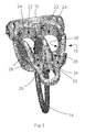
Figures 1 to 3 are views of a belay device embodying the invention from the side, from below and from above; -
Figure 4 is an exploded view of the embodiment ofFigures 1 to 3 ; -
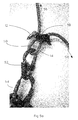
Figures 5a and5b show a belay device embodying the invention configured to operate in standard mode, respectively, with the rope free to move through the device and with the rope being gripped against movement by the device; -
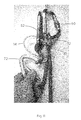
Figure 6 shows a belay device embodying the invention configured to operate in guide mode while rope is being drawn to protect a second who climber is ascending; -
Figure 7 shows a belay device embodying the invention configured to operate in guide mode while locked, holding a fallen climber -
Figure 8 is a cross-sectional view corresponding to the side view ofFigure 7 ; -
Figures 9 shows the embodiment of the invention while a fallen climber is being lowered using a sling to assist in release of the belay device; -
Figure 10 is a cross-sectional view that corresponds toFigure 9 showing the path of a rope through the belay device; -
Figure 11 shows a carabiner being connected to the belay device to be used as a lever to assist in lowering of a fallen climber; -
Figure 12 illustrates the forces and sources of leverage that arise during lowering of a climber using an embodiment of the invention; and -
Figure 13 illustrates the forces and sources of leverage that arise during lowering of a climber using a known guide-mode belay device. - With reference to
Figures 1 to 4 , a belay device comprises the following principal components: abody 10, a guide-mode anchor 12 and akeeper cable 14. - The
body 10 of this embodiment is formed as from a single piece of metal, in this case, a light aluminium alloy. Tworope slots 22 are formed through thebody 10. Eachslot 22 has spaced, generally parallel side walls that are interconnected by arounded end wall 24 at one end of the slot. At the opposite end of eachslot 22, a U-shapedrope passage 26 extends from eachslot 22.Multiple grooves 28 are formed in therope passage 26. A guide-mode release hole 30 is formed through a region of thebody 10 that extends beyond and between therope passages 26 in a direction away from the guide mode anchor to constitute a release formation of the device. Apivot hole 32 extends transversely through thebody 10 adjacent to theend walls 24 of theslots 22, flat bearingsurfaces 34 surrounding each end of thepivot hole 32. - The
keeper cable 14 comprises a length of steel cable enclosed within a protective sleeve. End portions of thekeeper cable 14 are secured within thebody 10, one end portion being between theend walls 24 and the other being between therope passages 26, such that thekeeper cable 14 forms a U-shaped loop that extends from thebody 10. - The guide-
mode anchor 12 is formed from an approximately semi-circular single piece of metal, light aluminium alloy in this embodiment. End portions of the guide-mode anchor 12 are formed asconnection regions 36, each having mutually facing flat bearing surfaces through each of which apivot hole 38 passes, the pivot holes being coaxial. The bearing surfaces of the guide-mode anchor 12 are spaced apart a small distance more than the spacing between thebearing surfaces 34 of thebody 10. - A
spindle 40 has a shaft that passes through the pivot holes 32, 38 of thebody 10 and the guide-mode anchor 12. Thespindle 40 is retained by an integral head and by being riveted at an end opposite to the head. The shaft is a close sliding fit in the pivot holes, whereby the guide-mode anchor 12 is secured to thebody 10, but can pivot with respect to it about a pivot axis that is generally coincident with the axis of the shaft of thespindle 40. The guide-mode anchor 12 therefore forms a closed loop with thebody 10. - Note that the two
slots 22 are essentially identical and can be used interchangeably. Two slots are provided in this embodiment to allow the belayer to control two ropes in both standard and guide-mode configurations. - Operation of the belay device will now be described.
- First, and with reference to
Figures 5a and5b , operation of the device in standard belay mode will be described. - To set up the device in standard mode, a
bight 50 of climbing rope is passed through either one of theslots 22 such that thebight 50 lies adjacent to thekeeper cable 14. Acarabiner 52 is then connected through thebight 50 and thekeeper cable 14 and locked. Thecarabiner 52 is also connected to abelay loop 54 that is part of a harness worn by a belayer. The rope is now pulled tight such that thecarabiner 52 is drawn into contact with thebody 10, so preventing the rope from coming out of the slot. A working length of the rope passes from theslot 22, as shown at 56, adjacent to the guide-mode anchor 12 upward to a leading climber that is being belayed, and a free length of rope, shown at 58, passes from theslot 22 through therope passage 26. - During normal climbing, there is slack in the
bight 50, as shown inFigure 5a , which allows the rope to slide in either direction through the device. The device can be caused to apply friction to the rope by applying tension to thefree length 58, such that thebight 50 of rope is pulled tight, as shown inFigure 5b . The amount of friction that the belay device applies to the rope is controlled by the belayer varying the tension applied to thefree length 58. Note that if thefree length 58 of rope is released, the force applied by the belay device to the rope is minimal, so the person climbing will not be protected. - The above arrangement can be contrasted to the arrangement shown in
Figure 6 , in which a lead climber is belaying a second in guide mode. - As in standard mode, a bight of
rope 50 is passed through eitherslot 22, and acarabiner 52 is passed through thebight 50 and thekeeper cable 14, and thecarabiner 52 is then locked. However, in guide mode, thecarabiner 52 is not otherwise connected. A working length of rope, shown at 56, is connected to the harness of a second climber, and a free length of rope, shown at 58, which is held and controlled by the lead climber acting as belayer. Thefree length 58 extends from the body through therope passage 26, and the workinglength 56 lies on top of it. An anchoringcarabiner 60 is passed through the loop formed by the guide-mode anchor 12 and is locked. The anchoringcarabiner 60 is also connected directly or indirectly to a fixed anchor, such as a rock bolt. - In both modes, the purpose of the
keeper cable 14 is to keep the device from sliding up or down the rope and out of reach and control of the belayer. It also provides a means for connecting thecarabiner 52 to the device when it is not in use, and there is no rope present. - In guide mode, as a second climber ascends, slack is introduced into the working
length 56. The belayer pulls on thefree length 58 to take in that slack through the device. To assist this operation, the belayer may raise the working length ofrope 56 off thefree length 58, thereby reducing the mutual friction between them and enable the rope to be taken in easily. Provided there is no tension in the working length ofrope 56 then this can be done in reverse to feed out slack to the second, for example if the climber needs to climb down. - In the event that a second climber being belayed falls, the load on the working
length 56 increases. The bight of rope that surrounds thecarabiner 52 tightens, the immediately adjacent potions of thefree length 58 and the workinglength 56 are pressed together, and the adjacent potion of thefree length 58 is pressed into the base of therope passage 26. The mutual friction between thelengths carabiner 52, and the rope and the rope passage 26 (enhanced by the presence of the grooves 28) prevents the rope from sliding through the belay device. Thus, the weight of the fallen climber is borne by the workinglength 56 of the rope through thebody 10 and the guide-mode anchor 12 to the anchoringcarabiner 60. - In the event that a fallen belayed climber cannot resume climbing, the climber may have to be lowered while suspended from the working
length 56 of the rope. To achieve this, the friction applied to therope body 10 in the region of the guide-mode release hole 30 so that thebody 10 rotates in a direction that it clockwise in the figures. - It will be appreciated that when the device is rotated the climber suspended from the working
length 56 is lifted, and doing this requires considerable force to be applied to thebody 10. This force must be applied manually by the belayer. One arrangement for providing such a force is provided by connecting textile webbing or cord, such as a sling, 70 through the guide-mode release hole 30 and redirecting it in such a way that the belayer's body weight can be utilised to lift the device, while movement of thefree portion 58 of the rope is controlled. This arrangement is partially shown inFigures 9 and 10 . Alternatively, a lever can be inserted into the guide-mode release hole 30 to gain mechanical advantage over the weight of the climber, allowing the belayer to lift the device by hand. It is common to use acarabiner 72 as a lever in this operation, as shown inFigures 11 and12 , since this is an article that a climber will normally be carrying. - With reference now to
Figure 12 , the release force Fr that must be applied at the guide-mode release hole 30 acts against the weight Fw of the fallen climber with a mechanical advantage that is determined by a ratio of lengths A/B determined by the geometry of the belay device. Length A is the horizontal component of the distance from the workinglength 56 of the rope to the guide-mode release hole 30. Length B is the horizontal component of the distance from the workinglength 56 of the rope to the axis about which the body pivots to release the rope, which is, in this embodiment, the axis about which the guide-mode anchor 12 can pivot around thespindle 40 with respect to thebody 10. - The corresponding lengths in a belay device that is already known is shown in
Figure 13 . In the conventional device, the body pivots directly on a carabiner that is passed through a hole in thebody 10. - In order to increase the mechanical advantage, either the value of A can be increased or the value of B decreased. Increasing A is undesirable, because it increases the size and weight of the belay device. In the case of the prior art, the minimum value of B is determined by the need to provide a guide-
mode anchor 12 of sufficient size that the device can be used conveniently with carabiners of a range of sizes. - In contrast, in embodiments of the invention, the guide-
mode anchor 12 can be pivoted outward to a configuration shown in, for example,Figure 6 , which provides ample space for the belay device to be installed upon a rope. In this configuration, the total length of the device is comparable with that of a conventional belay device. However, when a climber is being lowered, the guide-mode anchor 12 is pivoted towards thebody 10 as shown inFigure 12 , thereby reducing the length B to a value that is considerably less than would be the case if the guide-mode anchor and thebody 10 were a single rigid component, so increasing the ratio A/B without increasing the length A and therefore without increasing the overall size of the belay device.
Claims (12)
- A belay device operable for guide mode belaying, the device comprising a body (10) that includes a rope slot (22) through which a bight of rope (50) can pass, a guide-mode anchor (12), and a release formation (30), the device being operative to cause frictional locking of a working length (56) of the rope in a condition of loading on the rope corresponding to that which occurs in the event of a fall of a belayed climber, characterised in that the guide-mode anchor is pivotally connected to the body, and arranged such that that when the rope is locked, the body (10) is caused by force applied to the release formation (30) to pivot with respect to the guide-mode anchor (12), which pivotal movement acts to increase mechanical advantage of the release formation (30) acting on a load applied by the working length (56) of the rope on the body (10).
- A belay device according to claim 1 in which the guide-mode anchor (12) is of a generally semi-circular shape, being pivotally coaxially connected to the body (10) at two opposite end portions.
- A belay device according to claim 1 or claim 2 in which an axis about which the guide-mode anchor (12) can pivot is generally transverse to a plane that would be occupied by a rope that is passed through the rope slot (22).
- A belay device according to any preceding claim that includes two or more rope slots (22), whereby two or more climbing seconds can be belayed.
- A belay device according to any preceding claim in which the release formation is constituted by an integral region of the body (10).
- A belay device according to claim 5 in which the release formation is a region of the body (10) that extends in a direction generally normal to a pivot axis of the guide mode anchor (12).
- A belay device according to any preceding claim including a hole (30) through the body (10) through which a lever (70) can be inserted to exert a force upon the body (10).
- A belay device according to any preceding claim in which a rope passage (26) extends from the or each slot (22).
- A belay device according to claim 8 in which friction inducing grooves (28) are formed in the rope passage (26).
- A belay device according to any preceding claim further including a keeper (14) to which a connection device (52) can be connected restrict the extent to which the belay device can slide along the rope.
- A belay arrangement comprising a device according to any preceding claim, a rope having a generally U-shaped bight (50), which bight passes through a slot (22) of the belay device, a first connection device (52) that passes through the bight to prevent its removal from the slot, and a second connection device (60) that connects the guide-mode anchor to a belaying point.
- A belay arrangement according to claim 11 in which the belaying point is a fixed anchor to which the belay device is directly or indirectly connected.
Applications Claiming Priority (1)
| Application Number | Priority Date | Filing Date | Title |
|---|---|---|---|
| GB1322007.4A GB2523073B (en) | 2013-12-12 | 2013-12-12 | Belay device |
Publications (3)
| Publication Number | Publication Date |
|---|---|
| EP2883574A2 true EP2883574A2 (en) | 2015-06-17 |
| EP2883574A3 EP2883574A3 (en) | 2015-08-19 |
| EP2883574B1 EP2883574B1 (en) | 2024-03-27 |
Family
ID=50030837
Family Applications (1)
| Application Number | Title | Priority Date | Filing Date |
|---|---|---|---|
| EP14197458.4A Active EP2883574B1 (en) | 2013-12-12 | 2014-12-11 | Belay device |
Country Status (2)
| Country | Link |
|---|---|
| EP (1) | EP2883574B1 (en) |
| GB (1) | GB2523073B (en) |
Family Cites Families (8)
| Publication number | Priority date | Publication date | Assignee | Title |
|---|---|---|---|---|
| DE10219492A1 (en) * | 2002-04-30 | 2003-11-13 | Bornack Gmbh & Co Kg | Automatic belay and descender |
| FR2884429B1 (en) * | 2005-04-19 | 2007-06-08 | Simond Soc Par Actions Simplif | BRAKING DEVICE AND BLOCKING OF ROPE |
| US7963366B2 (en) * | 2006-02-16 | 2011-06-21 | Tony Christianson | Split tube belay device |
| AT506720B1 (en) * | 2008-04-24 | 2011-08-15 | Anlo Mountain Gmbh | LIFELINE |
| EP2391254A1 (en) * | 2009-02-02 | 2011-12-07 | William H. Ayre | Rope handling device with secondary locking feature |
| FR2946258A1 (en) * | 2009-06-09 | 2010-12-10 | Simond Ets | Device for locking and blocking cord, has body elongated along longitudinal axis, and engagement unit arranged such that operating lever is connected in anterior-posterior passages and spaced from longitudinal axis |
| US8348016B2 (en) * | 2009-08-26 | 2013-01-08 | Lewis Richard W | Descender with fall arrest and controlled rate of descent |
| IT1403628B1 (en) * | 2011-01-13 | 2013-10-31 | Aludesign Spa | INSURER AND DISCENSOR DEVICE |
-
2013
- 2013-12-12 GB GB1322007.4A patent/GB2523073B/en active Active
-
2014
- 2014-12-11 EP EP14197458.4A patent/EP2883574B1/en active Active
Also Published As
| Publication number | Publication date |
|---|---|
| GB2523073A (en) | 2015-08-19 |
| GB2523073B (en) | 2016-03-02 |
| EP2883574A3 (en) | 2015-08-19 |
| EP2883574B1 (en) | 2024-03-27 |
| GB201322007D0 (en) | 2014-01-29 |
Similar Documents
| Publication | Publication Date | Title |
|---|---|---|
| US20110114415A1 (en) | Belay device with a sliding slack bar | |
| US20080149433A1 (en) | Advanced "omer" rescue system | |
| US6561313B2 (en) | Belay/rappel device for use in climbing activities and the like | |
| EP1820540B1 (en) | Split tube belay device | |
| TWI592193B (en) | Safety rope blocker having a rotatable body | |
| US20120193166A1 (en) | Descender with Self-Acting Brake | |
| US20080245611A1 (en) | Self-Belay And Rappel Device And Methods Of Use | |
| EP3797202B1 (en) | Fall control ladder | |
| US20160213953A1 (en) | Frictional rope control device with on the fly friction adjustment | |
| CN103313758A (en) | Safety and descender device | |
| US7500290B2 (en) | Simple climber's multi-tool | |
| US7353910B2 (en) | Simple belay device | |
| US20170050055A1 (en) | Auto-Blocking Rappelling and Belaying Device | |
| US10619417B2 (en) | Pass-through cable grab system | |
| US20240238625A1 (en) | Rope brake | |
| US20110011671A1 (en) | Belaying apparatus with friction claw for climbing | |
| EP3365069B1 (en) | Descender | |
| EP3831450A1 (en) | Remote clipping device | |
| EP2641635A2 (en) | Back-up apparatus for use in rope access | |
| US20200121962A1 (en) | Safer belay device | |
| EP2883574B1 (en) | Belay device | |
| US20080011543A1 (en) | Simple Climber's Multi-Tool | |
| WO2026002776A1 (en) | Rope blocker having a rotating cam, and a corresponding rope blocking method | |
| CZ18480U1 (en) | Belaying and rope-down aid � | |
| HK1093702A (en) | Rope/slider rescue system with anchoring device |
Legal Events
| Date | Code | Title | Description |
|---|---|---|---|
| PUAI | Public reference made under article 153(3) epc to a published international application that has entered the european phase |
Free format text: ORIGINAL CODE: 0009012 |
|
| 17P | Request for examination filed |
Effective date: 20141211 |
|
| AK | Designated contracting states |
Kind code of ref document: A2 Designated state(s): AL AT BE BG CH CY CZ DE DK EE ES FI FR GB GR HR HU IE IS IT LI LT LU LV MC MK MT NL NO PL PT RO RS SE SI SK SM TR |
|
| AX | Request for extension of the european patent |
Extension state: BA ME |
|
| PUAL | Search report despatched |
Free format text: ORIGINAL CODE: 0009013 |
|
| AK | Designated contracting states |
Kind code of ref document: A3 Designated state(s): AL AT BE BG CH CY CZ DE DK EE ES FI FR GB GR HR HU IE IS IT LI LT LU LV MC MK MT NL NO PL PT RO RS SE SI SK SM TR |
|
| AX | Request for extension of the european patent |
Extension state: BA ME |
|
| RIC1 | Information provided on ipc code assigned before grant |
Ipc: A62B 1/14 20060101AFI20150716BHEP Ipc: A63B 29/02 20060101ALI20150716BHEP |
|
| R17P | Request for examination filed (corrected) |
Effective date: 20160211 |
|
| RBV | Designated contracting states (corrected) |
Designated state(s): AL AT BE BG CH CY CZ DE DK EE ES FI FR GB GR HR HU IE IS IT LI LT LU LV MC MK MT NL NO PL PT RO RS SE SI SK SM TR |
|
| STAA | Information on the status of an ep patent application or granted ep patent |
Free format text: STATUS: EXAMINATION IS IN PROGRESS |
|
| 17Q | First examination report despatched |
Effective date: 20211026 |
|
| P01 | Opt-out of the competence of the unified patent court (upc) registered |
Effective date: 20230601 |
|
| GRAP | Despatch of communication of intention to grant a patent |
Free format text: ORIGINAL CODE: EPIDOSNIGR1 |
|
| STAA | Information on the status of an ep patent application or granted ep patent |
Free format text: STATUS: GRANT OF PATENT IS INTENDED |
|
| INTG | Intention to grant announced |
Effective date: 20231023 |
|
| GRAS | Grant fee paid |
Free format text: ORIGINAL CODE: EPIDOSNIGR3 |
|
| GRAA | (expected) grant |
Free format text: ORIGINAL CODE: 0009210 |
|
| STAA | Information on the status of an ep patent application or granted ep patent |
Free format text: STATUS: THE PATENT HAS BEEN GRANTED |
|
| AK | Designated contracting states |
Kind code of ref document: B1 Designated state(s): AL AT BE BG CH CY CZ DE DK EE ES FI FR GB GR HR HU IE IS IT LI LT LU LV MC MK MT NL NO PL PT RO RS SE SI SK SM TR |
|
| REG | Reference to a national code |
Ref country code: GB Ref legal event code: FG4D |
|
| REG | Reference to a national code |
Ref country code: CH Ref legal event code: EP |
|
| REG | Reference to a national code |
Ref country code: DE Ref legal event code: R096 Ref document number: 602014089776 Country of ref document: DE |
|
| REG | Reference to a national code |
Ref country code: IE Ref legal event code: FG4D |
|
| PG25 | Lapsed in a contracting state [announced via postgrant information from national office to epo] |
Ref country code: LT Free format text: LAPSE BECAUSE OF FAILURE TO SUBMIT A TRANSLATION OF THE DESCRIPTION OR TO PAY THE FEE WITHIN THE PRESCRIBED TIME-LIMIT Effective date: 20240327 |
|
| REG | Reference to a national code |
Ref country code: LT Ref legal event code: MG9D |
|
| PG25 | Lapsed in a contracting state [announced via postgrant information from national office to epo] |
Ref country code: GR Free format text: LAPSE BECAUSE OF FAILURE TO SUBMIT A TRANSLATION OF THE DESCRIPTION OR TO PAY THE FEE WITHIN THE PRESCRIBED TIME-LIMIT Effective date: 20240628 |
|
| PG25 | Lapsed in a contracting state [announced via postgrant information from national office to epo] |
Ref country code: HR Free format text: LAPSE BECAUSE OF FAILURE TO SUBMIT A TRANSLATION OF THE DESCRIPTION OR TO PAY THE FEE WITHIN THE PRESCRIBED TIME-LIMIT Effective date: 20240327 Ref country code: RS Free format text: LAPSE BECAUSE OF FAILURE TO SUBMIT A TRANSLATION OF THE DESCRIPTION OR TO PAY THE FEE WITHIN THE PRESCRIBED TIME-LIMIT Effective date: 20240627 |
|
| PG25 | Lapsed in a contracting state [announced via postgrant information from national office to epo] |
Ref country code: RS Free format text: LAPSE BECAUSE OF FAILURE TO SUBMIT A TRANSLATION OF THE DESCRIPTION OR TO PAY THE FEE WITHIN THE PRESCRIBED TIME-LIMIT Effective date: 20240627 Ref country code: NO Free format text: LAPSE BECAUSE OF FAILURE TO SUBMIT A TRANSLATION OF THE DESCRIPTION OR TO PAY THE FEE WITHIN THE PRESCRIBED TIME-LIMIT Effective date: 20240627 Ref country code: LT Free format text: LAPSE BECAUSE OF FAILURE TO SUBMIT A TRANSLATION OF THE DESCRIPTION OR TO PAY THE FEE WITHIN THE PRESCRIBED TIME-LIMIT Effective date: 20240327 Ref country code: HR Free format text: LAPSE BECAUSE OF FAILURE TO SUBMIT A TRANSLATION OF THE DESCRIPTION OR TO PAY THE FEE WITHIN THE PRESCRIBED TIME-LIMIT Effective date: 20240327 Ref country code: GR Free format text: LAPSE BECAUSE OF FAILURE TO SUBMIT A TRANSLATION OF THE DESCRIPTION OR TO PAY THE FEE WITHIN THE PRESCRIBED TIME-LIMIT Effective date: 20240628 Ref country code: FI Free format text: LAPSE BECAUSE OF FAILURE TO SUBMIT A TRANSLATION OF THE DESCRIPTION OR TO PAY THE FEE WITHIN THE PRESCRIBED TIME-LIMIT Effective date: 20240327 Ref country code: BG Free format text: LAPSE BECAUSE OF FAILURE TO SUBMIT A TRANSLATION OF THE DESCRIPTION OR TO PAY THE FEE WITHIN THE PRESCRIBED TIME-LIMIT Effective date: 20240327 |
|
| REG | Reference to a national code |
Ref country code: NL Ref legal event code: MP Effective date: 20240327 |
|
| PG25 | Lapsed in a contracting state [announced via postgrant information from national office to epo] |
Ref country code: SE Free format text: LAPSE BECAUSE OF FAILURE TO SUBMIT A TRANSLATION OF THE DESCRIPTION OR TO PAY THE FEE WITHIN THE PRESCRIBED TIME-LIMIT Effective date: 20240327 Ref country code: LV Free format text: LAPSE BECAUSE OF FAILURE TO SUBMIT A TRANSLATION OF THE DESCRIPTION OR TO PAY THE FEE WITHIN THE PRESCRIBED TIME-LIMIT Effective date: 20240327 |
|
| PG25 | Lapsed in a contracting state [announced via postgrant information from national office to epo] |
Ref country code: NL Free format text: LAPSE BECAUSE OF FAILURE TO SUBMIT A TRANSLATION OF THE DESCRIPTION OR TO PAY THE FEE WITHIN THE PRESCRIBED TIME-LIMIT Effective date: 20240327 |
|
| REG | Reference to a national code |
Ref country code: AT Ref legal event code: MK05 Ref document number: 1669363 Country of ref document: AT Kind code of ref document: T Effective date: 20240327 |
|
| PG25 | Lapsed in a contracting state [announced via postgrant information from national office to epo] |
Ref country code: NL Free format text: LAPSE BECAUSE OF FAILURE TO SUBMIT A TRANSLATION OF THE DESCRIPTION OR TO PAY THE FEE WITHIN THE PRESCRIBED TIME-LIMIT Effective date: 20240327 |
|
| PG25 | Lapsed in a contracting state [announced via postgrant information from national office to epo] |
Ref country code: IS Free format text: LAPSE BECAUSE OF FAILURE TO SUBMIT A TRANSLATION OF THE DESCRIPTION OR TO PAY THE FEE WITHIN THE PRESCRIBED TIME-LIMIT Effective date: 20240727 |
|
| PG25 | Lapsed in a contracting state [announced via postgrant information from national office to epo] |
Ref country code: PT Free format text: LAPSE BECAUSE OF FAILURE TO SUBMIT A TRANSLATION OF THE DESCRIPTION OR TO PAY THE FEE WITHIN THE PRESCRIBED TIME-LIMIT Effective date: 20240729 Ref country code: SM Free format text: LAPSE BECAUSE OF FAILURE TO SUBMIT A TRANSLATION OF THE DESCRIPTION OR TO PAY THE FEE WITHIN THE PRESCRIBED TIME-LIMIT Effective date: 20240327 |
|
| PG25 | Lapsed in a contracting state [announced via postgrant information from national office to epo] |
Ref country code: ES Free format text: LAPSE BECAUSE OF FAILURE TO SUBMIT A TRANSLATION OF THE DESCRIPTION OR TO PAY THE FEE WITHIN THE PRESCRIBED TIME-LIMIT Effective date: 20240327 |
|
| PG25 | Lapsed in a contracting state [announced via postgrant information from national office to epo] |
Ref country code: EE Free format text: LAPSE BECAUSE OF FAILURE TO SUBMIT A TRANSLATION OF THE DESCRIPTION OR TO PAY THE FEE WITHIN THE PRESCRIBED TIME-LIMIT Effective date: 20240327 |
|
| PG25 | Lapsed in a contracting state [announced via postgrant information from national office to epo] |
Ref country code: AT Free format text: LAPSE BECAUSE OF FAILURE TO SUBMIT A TRANSLATION OF THE DESCRIPTION OR TO PAY THE FEE WITHIN THE PRESCRIBED TIME-LIMIT Effective date: 20240327 |
|
| PG25 | Lapsed in a contracting state [announced via postgrant information from national office to epo] |
Ref country code: PL Free format text: LAPSE BECAUSE OF FAILURE TO SUBMIT A TRANSLATION OF THE DESCRIPTION OR TO PAY THE FEE WITHIN THE PRESCRIBED TIME-LIMIT Effective date: 20240327 |
|
| PG25 | Lapsed in a contracting state [announced via postgrant information from national office to epo] |
Ref country code: SK Free format text: LAPSE BECAUSE OF FAILURE TO SUBMIT A TRANSLATION OF THE DESCRIPTION OR TO PAY THE FEE WITHIN THE PRESCRIBED TIME-LIMIT Effective date: 20240327 |
|
| PG25 | Lapsed in a contracting state [announced via postgrant information from national office to epo] |
Ref country code: SM Free format text: LAPSE BECAUSE OF FAILURE TO SUBMIT A TRANSLATION OF THE DESCRIPTION OR TO PAY THE FEE WITHIN THE PRESCRIBED TIME-LIMIT Effective date: 20240327 Ref country code: SK Free format text: LAPSE BECAUSE OF FAILURE TO SUBMIT A TRANSLATION OF THE DESCRIPTION OR TO PAY THE FEE WITHIN THE PRESCRIBED TIME-LIMIT Effective date: 20240327 Ref country code: RO Free format text: LAPSE BECAUSE OF FAILURE TO SUBMIT A TRANSLATION OF THE DESCRIPTION OR TO PAY THE FEE WITHIN THE PRESCRIBED TIME-LIMIT Effective date: 20240327 Ref country code: PT Free format text: LAPSE BECAUSE OF FAILURE TO SUBMIT A TRANSLATION OF THE DESCRIPTION OR TO PAY THE FEE WITHIN THE PRESCRIBED TIME-LIMIT Effective date: 20240729 Ref country code: PL Free format text: LAPSE BECAUSE OF FAILURE TO SUBMIT A TRANSLATION OF THE DESCRIPTION OR TO PAY THE FEE WITHIN THE PRESCRIBED TIME-LIMIT Effective date: 20240327 Ref country code: IS Free format text: LAPSE BECAUSE OF FAILURE TO SUBMIT A TRANSLATION OF THE DESCRIPTION OR TO PAY THE FEE WITHIN THE PRESCRIBED TIME-LIMIT Effective date: 20240727 Ref country code: ES Free format text: LAPSE BECAUSE OF FAILURE TO SUBMIT A TRANSLATION OF THE DESCRIPTION OR TO PAY THE FEE WITHIN THE PRESCRIBED TIME-LIMIT Effective date: 20240327 Ref country code: EE Free format text: LAPSE BECAUSE OF FAILURE TO SUBMIT A TRANSLATION OF THE DESCRIPTION OR TO PAY THE FEE WITHIN THE PRESCRIBED TIME-LIMIT Effective date: 20240327 Ref country code: AT Free format text: LAPSE BECAUSE OF FAILURE TO SUBMIT A TRANSLATION OF THE DESCRIPTION OR TO PAY THE FEE WITHIN THE PRESCRIBED TIME-LIMIT Effective date: 20240327 |
|
| REG | Reference to a national code |
Ref country code: DE Ref legal event code: R097 Ref document number: 602014089776 Country of ref document: DE |
|
| PG25 | Lapsed in a contracting state [announced via postgrant information from national office to epo] |
Ref country code: DK Free format text: LAPSE BECAUSE OF FAILURE TO SUBMIT A TRANSLATION OF THE DESCRIPTION OR TO PAY THE FEE WITHIN THE PRESCRIBED TIME-LIMIT Effective date: 20240327 |
|
| PG25 | Lapsed in a contracting state [announced via postgrant information from national office to epo] |
Ref country code: DK Free format text: LAPSE BECAUSE OF FAILURE TO SUBMIT A TRANSLATION OF THE DESCRIPTION OR TO PAY THE FEE WITHIN THE PRESCRIBED TIME-LIMIT Effective date: 20240327 |
|
| PLBE | No opposition filed within time limit |
Free format text: ORIGINAL CODE: 0009261 |
|
| STAA | Information on the status of an ep patent application or granted ep patent |
Free format text: STATUS: NO OPPOSITION FILED WITHIN TIME LIMIT |
|
| 26N | No opposition filed |
Effective date: 20250103 |
|
| PG25 | Lapsed in a contracting state [announced via postgrant information from national office to epo] |
Ref country code: SI Free format text: LAPSE BECAUSE OF FAILURE TO SUBMIT A TRANSLATION OF THE DESCRIPTION OR TO PAY THE FEE WITHIN THE PRESCRIBED TIME-LIMIT Effective date: 20240327 |
|
| PG25 | Lapsed in a contracting state [announced via postgrant information from national office to epo] |
Ref country code: MC Free format text: LAPSE BECAUSE OF FAILURE TO SUBMIT A TRANSLATION OF THE DESCRIPTION OR TO PAY THE FEE WITHIN THE PRESCRIBED TIME-LIMIT Effective date: 20240327 |
|
| PG25 | Lapsed in a contracting state [announced via postgrant information from national office to epo] |
Ref country code: LU Free format text: LAPSE BECAUSE OF NON-PAYMENT OF DUE FEES Effective date: 20241211 |
|
| REG | Reference to a national code |
Ref country code: BE Ref legal event code: MM Effective date: 20241231 |
|
| PG25 | Lapsed in a contracting state [announced via postgrant information from national office to epo] |
Ref country code: BE Free format text: LAPSE BECAUSE OF NON-PAYMENT OF DUE FEES Effective date: 20241231 |
|
| PG25 | Lapsed in a contracting state [announced via postgrant information from national office to epo] |
Ref country code: IE Free format text: LAPSE BECAUSE OF NON-PAYMENT OF DUE FEES Effective date: 20241211 |
|
| REG | Reference to a national code |
Ref country code: CH Ref legal event code: U11 Free format text: ST27 STATUS EVENT CODE: U-0-0-U10-U11 (AS PROVIDED BY THE NATIONAL OFFICE) Effective date: 20260101 |
|
| PGFP | Annual fee paid to national office [announced via postgrant information from national office to epo] |
Ref country code: DE Payment date: 20251105 Year of fee payment: 12 |
|
| PGFP | Annual fee paid to national office [announced via postgrant information from national office to epo] |
Ref country code: GB Payment date: 20251104 Year of fee payment: 12 |
|
| PGFP | Annual fee paid to national office [announced via postgrant information from national office to epo] |
Ref country code: IT Payment date: 20251121 Year of fee payment: 12 |
|
| PGFP | Annual fee paid to national office [announced via postgrant information from national office to epo] |
Ref country code: FR Payment date: 20251104 Year of fee payment: 12 |
|
| PGFP | Annual fee paid to national office [announced via postgrant information from national office to epo] |
Ref country code: CZ Payment date: 20251110 Year of fee payment: 12 |
|
| PGFP | Annual fee paid to national office [announced via postgrant information from national office to epo] |
Ref country code: CH Payment date: 20260101 Year of fee payment: 12 |
|
| PG25 | Lapsed in a contracting state [announced via postgrant information from national office to epo] |
Ref country code: CY Free format text: LAPSE BECAUSE OF FAILURE TO SUBMIT A TRANSLATION OF THE DESCRIPTION OR TO PAY THE FEE WITHIN THE PRESCRIBED TIME-LIMIT Effective date: 20240327 |
|
| PG25 | Lapsed in a contracting state [announced via postgrant information from national office to epo] |
Ref country code: TR Free format text: LAPSE BECAUSE OF FAILURE TO SUBMIT A TRANSLATION OF THE DESCRIPTION OR TO PAY THE FEE WITHIN THE PRESCRIBED TIME-LIMIT Effective date: 20240327 |
|
| PG25 | Lapsed in a contracting state [announced via postgrant information from national office to epo] |
Ref country code: HU Free format text: LAPSE BECAUSE OF FAILURE TO SUBMIT A TRANSLATION OF THE DESCRIPTION OR TO PAY THE FEE WITHIN THE PRESCRIBED TIME-LIMIT; INVALID AB INITIO Effective date: 20141211 |