EP2883556B1 - Aspiration system for thrombectomy procedures - Google Patents
Aspiration system for thrombectomy procedures Download PDFInfo
- Publication number
- EP2883556B1 EP2883556B1 EP14196918.8A EP14196918A EP2883556B1 EP 2883556 B1 EP2883556 B1 EP 2883556B1 EP 14196918 A EP14196918 A EP 14196918A EP 2883556 B1 EP2883556 B1 EP 2883556B1
- Authority
- EP
- European Patent Office
- Prior art keywords
- tube portion
- pump
- catheter
- wire
- tube
- Prior art date
- Legal status (The legal status is an assumption and is not a legal conclusion. Google has not performed a legal analysis and makes no representation as to the accuracy of the status listed.)
- Not-in-force
Links
- 238000013151 thrombectomy Methods 0.000 title claims description 37
- 238000000034 method Methods 0.000 title claims description 16
- 239000002245 particle Substances 0.000 claims description 31
- 239000012530 fluid Substances 0.000 claims description 24
- 238000004891 communication Methods 0.000 claims description 11
- 230000002792 vascular Effects 0.000 claims description 5
- 238000003780 insertion Methods 0.000 description 11
- 230000037431 insertion Effects 0.000 description 11
- 239000000463 material Substances 0.000 description 10
- 239000008280 blood Substances 0.000 description 7
- 210000004369 blood Anatomy 0.000 description 7
- 210000001627 cerebral artery Anatomy 0.000 description 5
- 230000007246 mechanism Effects 0.000 description 5
- 230000002966 stenotic effect Effects 0.000 description 5
- 208000007536 Thrombosis Diseases 0.000 description 3
- 210000004556 brain Anatomy 0.000 description 3
- 210000000275 circle of willis Anatomy 0.000 description 3
- 210000001105 femoral artery Anatomy 0.000 description 3
- 239000012634 fragment Substances 0.000 description 3
- 238000003384 imaging method Methods 0.000 description 3
- 238000002347 injection Methods 0.000 description 3
- 239000007924 injection Substances 0.000 description 3
- 238000013459 approach Methods 0.000 description 2
- 210000001367 artery Anatomy 0.000 description 2
- 230000009172 bursting Effects 0.000 description 2
- 239000003638 chemical reducing agent Substances 0.000 description 2
- 230000008878 coupling Effects 0.000 description 2
- 238000010168 coupling process Methods 0.000 description 2
- 238000005859 coupling reaction Methods 0.000 description 2
- 230000002439 hemostatic effect Effects 0.000 description 2
- 230000002262 irrigation Effects 0.000 description 2
- 238000003973 irrigation Methods 0.000 description 2
- 239000007788 liquid Substances 0.000 description 2
- 230000001732 thrombotic effect Effects 0.000 description 2
- 210000005166 vasculature Anatomy 0.000 description 2
- 208000030453 Drug-Related Side Effects and Adverse reaction Diseases 0.000 description 1
- 208000032843 Hemorrhage Diseases 0.000 description 1
- 108010023197 Streptokinase Proteins 0.000 description 1
- 206010070863 Toxicity to various agents Diseases 0.000 description 1
- 108090000435 Urokinase-type plasminogen activator Proteins 0.000 description 1
- 102000003990 Urokinase-type plasminogen activator Human genes 0.000 description 1
- 210000002551 anterior cerebral artery Anatomy 0.000 description 1
- 208000034158 bleeding Diseases 0.000 description 1
- 230000000740 bleeding effect Effects 0.000 description 1
- 230000017531 blood circulation Effects 0.000 description 1
- 230000036760 body temperature Effects 0.000 description 1
- 230000001413 cellular effect Effects 0.000 description 1
- 230000002490 cerebral effect Effects 0.000 description 1
- 239000003795 chemical substances by application Substances 0.000 description 1
- 238000001514 detection method Methods 0.000 description 1
- 238000010586 diagram Methods 0.000 description 1
- 230000003073 embolic effect Effects 0.000 description 1
- 239000003527 fibrinolytic agent Substances 0.000 description 1
- 210000003657 middle cerebral artery Anatomy 0.000 description 1
- 230000002093 peripheral effect Effects 0.000 description 1
- 230000002572 peristaltic effect Effects 0.000 description 1
- 229920000642 polymer Polymers 0.000 description 1
- 210000003388 posterior cerebral artery Anatomy 0.000 description 1
- 208000037803 restenosis Diseases 0.000 description 1
- 239000000523 sample Substances 0.000 description 1
- 239000012781 shape memory material Substances 0.000 description 1
- 229960005202 streptokinase Drugs 0.000 description 1
- 238000001356 surgical procedure Methods 0.000 description 1
- 229960000103 thrombolytic agent Drugs 0.000 description 1
- 230000000472 traumatic effect Effects 0.000 description 1
- 229960005356 urokinase Drugs 0.000 description 1
Images


Classifications
-
- A—HUMAN NECESSITIES
- A61—MEDICAL OR VETERINARY SCIENCE; HYGIENE
- A61B—DIAGNOSIS; SURGERY; IDENTIFICATION
- A61B17/00—Surgical instruments, devices or methods
- A61B17/32—Surgical cutting instruments
- A61B17/3205—Excision instruments
- A61B17/3207—Atherectomy devices working by cutting or abrading; Similar devices specially adapted for non-vascular obstructions
- A61B17/320758—Atherectomy devices working by cutting or abrading; Similar devices specially adapted for non-vascular obstructions with a rotating cutting instrument, e.g. motor driven
-
- A—HUMAN NECESSITIES
- A61—MEDICAL OR VETERINARY SCIENCE; HYGIENE
- A61B—DIAGNOSIS; SURGERY; IDENTIFICATION
- A61B17/00—Surgical instruments, devices or methods
- A61B17/22—Implements for squeezing-off ulcers or the like on inner organs of the body; Implements for scraping-out cavities of body organs, e.g. bones; for invasive removal or destruction of calculus using mechanical vibrations; for removing obstructions in blood vessels, not otherwise provided for
-
- A—HUMAN NECESSITIES
- A61—MEDICAL OR VETERINARY SCIENCE; HYGIENE
- A61M—DEVICES FOR INTRODUCING MEDIA INTO, OR ONTO, THE BODY; DEVICES FOR TRANSDUCING BODY MEDIA OR FOR TAKING MEDIA FROM THE BODY; DEVICES FOR PRODUCING OR ENDING SLEEP OR STUPOR
- A61M1/00—Suction or pumping devices for medical purposes; Devices for carrying-off, for treatment of, or for carrying-over, body-liquids; Drainage systems
- A61M1/69—Drainage containers not being adapted for subjection to vacuum, e.g. bags
-
- A—HUMAN NECESSITIES
- A61—MEDICAL OR VETERINARY SCIENCE; HYGIENE
- A61M—DEVICES FOR INTRODUCING MEDIA INTO, OR ONTO, THE BODY; DEVICES FOR TRANSDUCING BODY MEDIA OR FOR TAKING MEDIA FROM THE BODY; DEVICES FOR PRODUCING OR ENDING SLEEP OR STUPOR
- A61M1/00—Suction or pumping devices for medical purposes; Devices for carrying-off, for treatment of, or for carrying-over, body-liquids; Drainage systems
- A61M1/84—Drainage tubes; Aspiration tips
-
- A—HUMAN NECESSITIES
- A61—MEDICAL OR VETERINARY SCIENCE; HYGIENE
- A61M—DEVICES FOR INTRODUCING MEDIA INTO, OR ONTO, THE BODY; DEVICES FOR TRANSDUCING BODY MEDIA OR FOR TAKING MEDIA FROM THE BODY; DEVICES FOR PRODUCING OR ENDING SLEEP OR STUPOR
- A61M25/00—Catheters; Hollow probes
- A61M25/01—Introducing, guiding, advancing, emplacing or holding catheters
- A61M25/06—Body-piercing guide needles or the like
- A61M25/0662—Guide tubes
-
- A—HUMAN NECESSITIES
- A61—MEDICAL OR VETERINARY SCIENCE; HYGIENE
- A61M—DEVICES FOR INTRODUCING MEDIA INTO, OR ONTO, THE BODY; DEVICES FOR TRANSDUCING BODY MEDIA OR FOR TAKING MEDIA FROM THE BODY; DEVICES FOR PRODUCING OR ENDING SLEEP OR STUPOR
- A61M39/00—Tubes, tube connectors, tube couplings, valves, access sites or the like, specially adapted for medical use
- A61M39/02—Access sites
- A61M39/06—Haemostasis valves, i.e. gaskets sealing around a needle, catheter or the like, closing on removal thereof
-
- A—HUMAN NECESSITIES
- A61—MEDICAL OR VETERINARY SCIENCE; HYGIENE
- A61M—DEVICES FOR INTRODUCING MEDIA INTO, OR ONTO, THE BODY; DEVICES FOR TRANSDUCING BODY MEDIA OR FOR TAKING MEDIA FROM THE BODY; DEVICES FOR PRODUCING OR ENDING SLEEP OR STUPOR
- A61M39/00—Tubes, tube connectors, tube couplings, valves, access sites or the like, specially adapted for medical use
- A61M39/22—Valves or arrangement of valves
-
- A—HUMAN NECESSITIES
- A61—MEDICAL OR VETERINARY SCIENCE; HYGIENE
- A61B—DIAGNOSIS; SURGERY; IDENTIFICATION
- A61B17/00—Surgical instruments, devices or methods
- A61B2017/00017—Electrical control of surgical instruments
- A61B2017/00115—Electrical control of surgical instruments with audible or visual output
-
- A—HUMAN NECESSITIES
- A61—MEDICAL OR VETERINARY SCIENCE; HYGIENE
- A61B—DIAGNOSIS; SURGERY; IDENTIFICATION
- A61B17/00—Surgical instruments, devices or methods
- A61B2017/00681—Aspects not otherwise provided for
- A61B2017/00734—Aspects not otherwise provided for battery operated
-
- A—HUMAN NECESSITIES
- A61—MEDICAL OR VETERINARY SCIENCE; HYGIENE
- A61B—DIAGNOSIS; SURGERY; IDENTIFICATION
- A61B17/00—Surgical instruments, devices or methods
- A61B17/22—Implements for squeezing-off ulcers or the like on inner organs of the body; Implements for scraping-out cavities of body organs, e.g. bones; for invasive removal or destruction of calculus using mechanical vibrations; for removing obstructions in blood vessels, not otherwise provided for
- A61B2017/22079—Implements for squeezing-off ulcers or the like on inner organs of the body; Implements for scraping-out cavities of body organs, e.g. bones; for invasive removal or destruction of calculus using mechanical vibrations; for removing obstructions in blood vessels, not otherwise provided for with suction of debris
-
- A—HUMAN NECESSITIES
- A61—MEDICAL OR VETERINARY SCIENCE; HYGIENE
- A61B—DIAGNOSIS; SURGERY; IDENTIFICATION
- A61B17/00—Surgical instruments, devices or methods
- A61B17/32—Surgical cutting instruments
- A61B17/3205—Excision instruments
- A61B17/3207—Atherectomy devices working by cutting or abrading; Similar devices specially adapted for non-vascular obstructions
- A61B2017/320733—Atherectomy devices working by cutting or abrading; Similar devices specially adapted for non-vascular obstructions with a flexible cutting or scraping element, e.g. with a whip-like distal filament member
-
- A—HUMAN NECESSITIES
- A61—MEDICAL OR VETERINARY SCIENCE; HYGIENE
- A61M—DEVICES FOR INTRODUCING MEDIA INTO, OR ONTO, THE BODY; DEVICES FOR TRANSDUCING BODY MEDIA OR FOR TAKING MEDIA FROM THE BODY; DEVICES FOR PRODUCING OR ENDING SLEEP OR STUPOR
- A61M1/00—Suction or pumping devices for medical purposes; Devices for carrying-off, for treatment of, or for carrying-over, body-liquids; Drainage systems
- A61M1/80—Suction pumps
- A61M1/81—Piston pumps, e.g. syringes
-
- A—HUMAN NECESSITIES
- A61—MEDICAL OR VETERINARY SCIENCE; HYGIENE
- A61M—DEVICES FOR INTRODUCING MEDIA INTO, OR ONTO, THE BODY; DEVICES FOR TRANSDUCING BODY MEDIA OR FOR TAKING MEDIA FROM THE BODY; DEVICES FOR PRODUCING OR ENDING SLEEP OR STUPOR
- A61M1/00—Suction or pumping devices for medical purposes; Devices for carrying-off, for treatment of, or for carrying-over, body-liquids; Drainage systems
- A61M1/84—Drainage tubes; Aspiration tips
- A61M1/85—Drainage tubes; Aspiration tips with gas or fluid supply means, e.g. for supplying rinsing fluids or anticoagulants
-
- A—HUMAN NECESSITIES
- A61—MEDICAL OR VETERINARY SCIENCE; HYGIENE
- A61M—DEVICES FOR INTRODUCING MEDIA INTO, OR ONTO, THE BODY; DEVICES FOR TRANSDUCING BODY MEDIA OR FOR TAKING MEDIA FROM THE BODY; DEVICES FOR PRODUCING OR ENDING SLEEP OR STUPOR
- A61M39/00—Tubes, tube connectors, tube couplings, valves, access sites or the like, specially adapted for medical use
- A61M39/22—Valves or arrangement of valves
- A61M2039/229—Stopcocks
-
- A—HUMAN NECESSITIES
- A61—MEDICAL OR VETERINARY SCIENCE; HYGIENE
- A61M—DEVICES FOR INTRODUCING MEDIA INTO, OR ONTO, THE BODY; DEVICES FOR TRANSDUCING BODY MEDIA OR FOR TAKING MEDIA FROM THE BODY; DEVICES FOR PRODUCING OR ENDING SLEEP OR STUPOR
- A61M2205/00—General characteristics of the apparatus
- A61M2205/33—Controlling, regulating or measuring
- A61M2205/3379—Masses, volumes, levels of fluids in reservoirs, flow rates
- A61M2205/3382—Upper level detectors
-
- A—HUMAN NECESSITIES
- A61—MEDICAL OR VETERINARY SCIENCE; HYGIENE
- A61M—DEVICES FOR INTRODUCING MEDIA INTO, OR ONTO, THE BODY; DEVICES FOR TRANSDUCING BODY MEDIA OR FOR TAKING MEDIA FROM THE BODY; DEVICES FOR PRODUCING OR ENDING SLEEP OR STUPOR
- A61M2205/00—General characteristics of the apparatus
- A61M2205/58—Means for facilitating use, e.g. by people with impaired vision
- A61M2205/587—Lighting arrangements
-
- A—HUMAN NECESSITIES
- A61—MEDICAL OR VETERINARY SCIENCE; HYGIENE
- A61M—DEVICES FOR INTRODUCING MEDIA INTO, OR ONTO, THE BODY; DEVICES FOR TRANSDUCING BODY MEDIA OR FOR TAKING MEDIA FROM THE BODY; DEVICES FOR PRODUCING OR ENDING SLEEP OR STUPOR
- A61M2205/00—General characteristics of the apparatus
- A61M2205/82—Internal energy supply devices
- A61M2205/8206—Internal energy supply devices battery-operated
Definitions
- This application relates to an aspiration pump and more particularly to an aspiration pump for use in thrombectomy or other vascular procedures.
- U.S. Patent No. 5,766,191 discloses a cage or basket composed of six memory wires that expand to press against the inner lumen to conform to the size and shape of the lumen.
- U.S. Patent No. 6,090,118 discloses a wire rotated to create a standing wave to break-up or macerate thrombus.
- the single wire is less traumatic than the aforedescribed basket device since it minimizes contact with the graft wall while still effectively mechanically removing thrombotic material.
- U.S. Patent No. 7,037,316 and 7,819,887 disclose another example of rotational thrombectomy wires for breaking up clots in grafts.
- the thrombectomy wire has a sinuous shape at its distal end and is contained within a sheath in a substantially straight non-deployed position. When the sheath is retracted, the distal portion of the wire is exposed to enable the wire to return to its non-linear sinuous configuration. Actuation of the motor causes rotational movement of the wire, creating a wave pattern, to macerate thrombus.
- the thrombectomy wire In neurovascular thrombectomy procedures, the thrombectomy wire needs to navigate tortuous vessels. That is, the wire is inserted through femoral artery and then must navigate small and tortuous vessels as it is advanced to the smaller cerebral arteries of the brain. Within the brain, the carotid and vertebrobasilar arteries meet to form the circle of Willis. From this circle, other arteries, e.g., the anterior cerebral artery, the middle cerebral artery and the posterior cerebral artery, arise and travel to various parts of the brain. Clots formed in these cerebral arteries can cause stroke and in certain instances death of the patient.
- 8,764,779 and 8,663,259 provide a thrombectomy device for breaking cerebral clots that strikes the optimal balance of flexibility and stiffness, thus effectively having the insertability of a tracking guidewire while enabling high speed rotation to effectively macerate clots without damaging vessels.
- US2012/157912 describes an assembly for a phacoemulsification surgical system which includes an aspiration system arranged to aspirate fluid from a surgical site.
- the two part form of independent claim 1 is based on this document.
- the aspiration system includes an aspiration path within the phacoemulsification hand piece and includes a flexible small bore aspiration tubing in fluid communication with the aspiration path.
- a high-output peristaltic pump communicates with the small bore aspiration tubing and is operable to create a flow through the small bore aspiration tubing.
- US4029097 describes a surgical sponge collector and drainage system which includes a tray having a smooth concave wall contoured for fitting directly against the human body and mounted in contact therewith.
- the tray includes a perforated shelf disposed below its peripheral rim as a discard area for collecting used sponges and permitting liquid to drain therethrough and ultimately drain to a collector.
- Aspirating tubes are also provided and inserted into the body at the operation site for withdrawing liquid therefrom into the same collector as from the tray.
- US2008/114301 describes methods, devices, and systems for detecting surgical fluids in a fluidics cassette.
- the fluid detection techniques make use of the changes in propagation of light through a portion of the holding tank when the portion varies between empty and full.
- WO98/34673 describes apparatus and methods for treating in-stent restenosis for removing stenotic material from within previously stented regions of a patient's vasculature.
- the apparatus includes a catheter system having a stenotic material removal mechanism mounted on a distal portion of an elongated inner catheter.
- a sensing means such as one or more sensing electrodes, are positioned on an outer surface of the apparatus.
- the apparatus optionally includes control means for diametrically expanding the stenotic material removal mechanism for effective recanalisation of the stent.
- a coaxial outer catheter is provided for aspirating stenotic material which is removed from within the stent.
- embolic filter apparatus are described for collecting the stenotic material removed from within the stent.
- US2002/165567 describes an apparatus for extracting an obstruction located in a patient's vessel by fragmenting the obstruction and conveying fragments of the obstruction through the apparatus and out of the patient's body, comprising a flexible tube having an open distal end and connectable to a negative pressure.
- a motor-rotated flexible spiral conveyor shaft disposed in the flexible tube conveys the obstruction fragments, cooperatively with the negative pressure, through the flexible tube.
- An offset agitator is connected to and rotated by the flexible conveyor shaft to fragment the obstruction. The offset agitator can be moved in and out of the flexible tube, through the open distal end, to adjust its effective diameter.
- WO87/01276 describes a method and apparatus for endoscopic removal of compliant biological tissues utilising an endoscopic ultrasonic aspirator comprising irrigation and aspiration means, a piezoelectric ultrasonic transducer, a first resonator such as a half-wave stepped velocity transformer, a probe including a second resonator such as a constant-stress velocity transformer, a blunt or modified working tip of open channel means or restricted tubular means for application of ultrasonic energy to cellular material, and a capacitative fluid sensor to detect the pressure of irrigation fluid adjacent these transforms within the instrument.
- an endoscopic ultrasonic aspirator comprising irrigation and aspiration means, a piezoelectric ultrasonic transducer, a first resonator such as a half-wave stepped velocity transformer, a probe including a second resonator such as a constant-stress velocity transformer, a blunt or modified working tip of open channel means or restricted tubular means for application of ultrasonic energy to cellular material, and a capacit
- the present invention advantageously provides an aspiration system for use in thrombectomy or other vascular procedures according to claim 1, comprising: a housing containing an aspiration pump and a chamber having an input port and an output port; a collection bag in fluid communication with the chamber; and a tubing assembly, the pump being activatable to aspirate particles through the input port into the chamber and to pump the aspirated particles out of the output port from the chamber through the tubing assembly into the collection bag, wherein the tubing assembly includes a first tube portion connected to the chamber and a connector to split the first tube portion into a second and third tube portion, the second tube portion configured to be connected in fluid communication with a first catheter to aspirate particles through the first catheter and the third tube portion configured to be connected in fluid communication with a second catheter to aspirate particles through the second catheter, and in that the collection bag and the first tube portion are configured during shipping with the collection bag and at least a substantial part of the first tube portion positioned beneath a base of the housing, the collecting bag being in a substantially flatt
- the connector comprises a T-fitting connected to an input end of the first tube portion and communicating with an output end of the second tube portion and an output end of the third tube portion.
- the aspiration pump can include a switch electrically connected to the pump to turn the pump on and off.
- An indicator can be included to provide an indication to the user that the collection bag is full.
- a controller when backpressure in the collection bag exceeds a predetermined amount, a controller will transmit a signal to the pump to shut off the pump.
- a non-conductive shipping tab is removable to complete a circuit to enable actuation of the pump.
- the collection bag can be positioned underneath a portion of the first tube portion.
- a first valve is connected with the second tube portion and a second valve is connected with the third tube portion, the first and second valves selectively actuable to enable fluid flow through the respective tube.
- the system includes a power pack for powering the pump.
- the power pack may be positioned in the housing, the housing having a top portion and a base and in a shipping configuration the tubing assembly having the first tube portion wrapped in a wound configuration and at least a substantial portion of the first tube portion is positioned underneath the base, and the collection bag is positioned underneath the substantial portion of the first tube portion in the shipping configuration.
- the present invention also provides in another aspect a disposable sterile aspiration kit, according to claim 10, comprising an aspiration system as hereinbefore defined in a sterile package.
- the second tube portion and the third tube portion may each be in fluid communication with the first tube portion and the split connector may separately connect with the second and third tube portions.
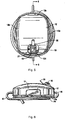
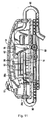
- Figure 1 illustrates the pump housing 11 and collection bag assembly 13 of the aspiration system 10 of the present invention, which are separated for clarity.
- the system 10 is designed for use with a thrombectomy apparatus, such as the thrombectomy apparatus 200 described in detail below.
- the system 10 can also be utilized for aspiration in conjunction with other thrombectomy devices as well as in other medical procedures requiring aspiration.
- pump housing 11 includes a top housing or cover 12 and a pump base 14. Contained within the pump housing 11 is an electrical subassembly 15 which includes an on/off power switch 16 protruding through opening 19 in top cover 12.
- the pump switch 16 can include a light to indicate when the switch is on to operate the pump to aspirate particles from the surgical site. Other types of indicators are also contemplated, including audible indicators.
- Aspiration system 10 also includes a tubing assembly 17 having bag tubing 80 and pump tubing 90, both described in detail below.
- Collection bag assembly 13 of system 10 includes a bag 21, shown in the flattened (unfilled) shipping position in Figures 1 and 3 , and a connector 24 for bag tubing 80.
- the collection bag 21 is shipped positioned underneath the base 14 and tubing assembly 17 to provide a compact unit to facilitate shipping and portability.
- Collection bag assembly 13 further includes a one way stopcock 20 to drain the collection bag 21 if desired by opening the valve.
- a second stopcock 22 can also be provided for collection bag drainage.
- An LED indicator 27, visible through top cover 12, provides an indicator when the collection bag 21 is full.
- Top cover 12 as shown in Figures 1 and 5 , has substantially linear sides 12a and 12b and curved ends 12c and 12d. Top cover 12 also has an opening 19 for the on/off switch 16.
- a non-conductive pull tab 30 extends though the opening 19 and breaks the circuit during shipping to prevent inadvertent actuation of the pump 10. This is best seen by comparing Figures 9 and 10 , wherein the distal end 30a of pull tab 30 is interposed between conductive plates 29a, 29b, positioned between respective posts 29c, 29d, and the proximal end 30b extends outside the pump housing 11 through opening 19 so it is accessible to the user.
- the pull tab 30 When desired to operate the pump 10, the pull tab 30 is moved in the direction of the arrow of Figure 10 , thereby allowing plates 29a, 29b to come into electrical contact to complete the circuit described below.
- Base 14 has a top surface 14a and a bottom surface 14b (see e.g., Figures 3 and 6 ). Bottom surface 14b is designed to rest on the table. Screws 40 extend through cylindrical posts 46, not all of which are labeled for clarity, to attach the top cover 12. Pads (not shown) can be provided on the screw heads to provide a smoother surface. Base 14 also includes a cutout 14c.
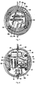
- the electrical subassembly includes a controller 53 and a motor pump 54.
- An output port 62 and an input port 60 extends from housing (chamber) 55.
- tubing assembly 17 includes bag tubing 80, pump tubing 90 and connector tube 70.
- Bag tubing 80 has a tube inlet end 82 which connects to T-connector 71 of connector tube 70 at connection port 74.
- Tube outlet end 84 of bag tubing 80 connects to the connector 24 ( Figure 3 ) of the collection bag assembly 13 to transport particles from bag tubing 80 into the bag 21.
- T-connector 71 is connected to output end 73 of connector tube 70.
- port 74 of T-connector 71 receives inlet end 82 of bag tubing 80.
- the other port (the 90 degree port) of T-connector 71 receives connector 77 which is connected to the controller 53.
- the controller 53 sends a signal to the pump 54 to turn off the pump 54 so that suction is terminated and the bag 21 is not overfilled which could result in the bursting of the bag 21.
- the opposing end 72 of connector tube 70 connects to the output port 62 of the chamber 55 (housing). In this manner, the blood or other particles are transported from chamber 55 through end 72 into connector tube 70, out through connection port 74, into inlet end 82, through bag tubing 80, out outlet end 84, into connector 24 and into collection bag 21.
- Pump tubing 90 includes a long tube 105, a connector tube 96 and short tube 94.
- T-connector 92 splits the fluid communication of long tube 105 into connector tube 96 and short tube 94 so that one tube connects to the guide catheter and the other tube connects to the thrombectomy catheter as described below.
- Tube 105 has one end 105a which connects to the input port 60 of the chamber 55 for application of suction.
- the tube 105 extends in a series of circular adjacent wraps.
- the opposing end 105b connects to tubes 94, 96 via T-connector. More specifically, T-convector 92 joins the input end 105b of long tube 105 to output end 94a of short tube 94 via its 90 degree port.
- Tube 94 extends in a somewhat partial S-shape as shown.
- short tube 94 fluidly joins catheter tubing 104 to long tube 105 as particles and blood from the thrombectomy catheter are aspirated through the lumen in the catheter into tubing 104, out end 104a into the lumen of valve 97, out of valve 97 and into input end 94b of short tube 94, out output end 94a of short tube 94, into input end 105b of long tube 105, and out end 105a of long tube 105 into the chamber (housing) 55 as end 105a is connected to inlet port 60 of housing 55.
- the switch valve 97 can be connected directly to the side port of the RHV, as shown for example in Figure 2A .
- the T-connector 92 also connects long tube 105 to connector tube 96 at output end 96a at its 180 degree port.
- the opposing end 96b of connector tube 96 extends into luer 99b of the switch valve 101.
- Short tube 96 extends in a circular fashion around an arc of about 270 degrees.
- Tubing 98 at the input end of the valve 101 is connected to the guide catheter.
- the switch valve 101 can be connected directly to the side port of the RHV, as shown for example in Figure 2A .
- the switch valve 97 can be selectively actuated to enable suction through the thrombectomy catheter described below and the switch valve 101 can be selectively actuated to enable suction through the guide catheter, also described below.
- the switch valves 97, 101 each have a slider mechanism 97a 101a, respectively, (see FIG. 7 ) which when slid in one direction clamps down on the respective tube (which forms the lumen in the switch valve for fluid/particle flow) to close off flow and when slid in the other direction unclamps the tube to enable suction.
- the slider mechanisms 97a, 101a are shown in the open position. When moved in the direction of the arrow, they are moved to a closed position to close off flow.
- Luer locks 97b, 99b provide the connection of tubes 94, 96 to the respective valve 97, 101.
- Switch 16 is connected to the positive terminal of the power pack 52 via wire 64a.
- Wire 64A splits at junction 64b so that wire 64c connects the power pack 52 to the LED indicator 27.
- the LED indicator 27 is connected to controller 53 via wire 64j.
- Switch 16 is also connected to controller 53 via wire 64d which provides an input signal to the controller 53 when the switch 16 is turned on.
- Switch 16 is further wired to the pump 54 via wire 64e.
- the negative terminal of the power pack 52 is connected via wire 64f to the conductive plate 29a.
- the opposing conductive plate 29b is connected to the controller via wire 64g.
- the controller 53 and pump 54 are connected via wire 64h.
- non-conductive tab 30 is seated between plates 29a, 29b to break the circuit.
- the controller 53 measures back pressure in the collection bag 21. As the bag 21 becomes fuller, it is more difficult to fill because it will not be expanded. When the back pressure rises to a predetermined amount, the controller 53 will transmit a signal to the pump 54 to shut off the pump 54. In this way, over expansion and potential bursting of the collection bag 21 is prevented.
- the pump 54 in one embodiment includes a piston actuated by a motor.
- a first direction e.g., outwardly with respect to the chamber 55
- blood and particles are suctioned through pump tubing 90
- the piston moves in the reverse direction, e.g., into the chamber 55
- the blood and particles are pumped from the chamber 55 into the bag tubing 80 and into the collection bag 21.
- the aspiration system of the present invention can be provided in a portable kit.
- the entire assembly (pump housing, tubing and collection bag) can be provided in a sterile package.
- the entire assembly in some embodiments can be disposable.
- the pump of the present invention can be used with a variety of devices to aspirate blood and/or particles.
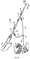
- thrombectomy apparatus is shown in Figures 2A and 2B and is designated generally by reference numeral 200.
- the apparatus includes a motor housing 212, a rotational thrombectomy wire 230, a rotating hemostatic valve (RHV) 240, an introducer sheath 260 and a telescoping tube or tubular connector 280.
- RVV rotating hemostatic valve
- the RHV 240 is connectable to an introducer catheter 300 discussed below in conjunction with the method of use (see e.g. Figure 2C ).
- the introducer sheath 260 is insertable into the RHV 240 to facilitate insertion of the thrombectomy wire 230 through the RHV 240 and introducer catheter 300.
- the thrombectomy apparatus or assembly 200 provides a rotational thrombectomy wire as a separate unit from a catheter. That is, the thrombectomy wire 230 is provided as a separate unit insertable through the RHV 240.
- the RHV 240 has a distal end 252 connected to a proximal end of the introducer catheter 300 (see Figure 2C ) to access the surgical site.
- the introducer sheath 260 aids insertion of the thrombectomy wire into the RHV 240 and through the introducer catheter 300, with the walls of the introducer sheath 260 maintaining the non-linear distal end of the wire 230 in a substantially straightened (substantially linear) configuration as it enters the RHV 240.
- the thrombectomy wire 230 of the present invention can be slid within the introducer sheath 260 and introducer catheter 300 prior to connection to the motor, if desired. This can aid introduction and manipulation of the wire 230 since it is less cumbersome and of lighter weight than if the motor housing was attached during manipulation of the wire.
- the wire 230 could be attached to the motor housing 212 prior to insertion through the introducer sheath 260, RHV 240 and the introducer catheter 300 and thus the wire 230 would be slidable within the introducer sheath 260 (and introducer catheter 300) with the motor housing 212 attached.
- the motor housing 212 can be attached to the wire at a desired time prior to or during the procedure.
- the motor housing 212 which also forms a handle portion, contains a motor and motor drive shaft extending therefrom.
- a gear reducer (not shown) could optionally be provided to reduce by way of example the rotational speed of the motor 252 from 15,000 rpm to 1500 rpm, 750 rpm, 150 rpm, etc.
- One or more batteries such as a 3 Volt battery, is positioned in the housing 212 for powering the motor 214.
- the motor drive shaft 215 connects at end 215a to a proximal end of the thrombectomy wire 230 by various couplings, such as for example a snap fit wherein cap 231 of at the proximal end of wire 230 is frictionally fit over the motor drive shaft 215.
- Various other types of connections are also contemplated such as magnetic couplers.
- a printed circuit board can also be provided within the housing 230 and is designated by reference numeral 218.
- Switch 219 extends though recess 221 in housing half 213a and in a corresponding recess in housing half 213b.
- a potentiometer (not shown) can optionally be wired to the motor to enable dialing the motor speed up or down to adjust the rotational speed of the thrombectomy wire 230 to adjust for various procedures and/or clot locations and sizes.
- the potentiometer is used as a two terminal variable resistor, i.e. a rheostat, by not connecting the third terminal. In this manner, in the initial position, the motor speed is at the desired minimum and rotation of a knob (or in alternate embodiments sliding of a knob) progressively increases the motor speed.
- the on/off switch 219 extending from the housing 212 is electrically connected to the motor 215 to turn on the motor 215 to activate the apparatus, i.e. rotate the wire 230.
- rotating hemostatic valve or housing 240 as noted above is connectable to an introducer catheter 300 (see Figure 2C ).
- a conventional introducer catheter can be utilized or alternatively a specially designed catheter for use with the apparatus of the present invention can be utilized.
- the RHV 240 is rotatable with respect to the catheter 300 to alter the orientation of the side arm 256.
- Side arm 256 extends from the tubular portion 246 of RHV 240 and has a port 257 for introduction of fluids and/or application of vacuum as described below.
- Luer lock is provided at the distal end 255 of RHV 240 to connect to the introducer catheter 300 as internal threads of rotation knob 252 threadingly engage external proximal threads of the introducer catheter 300.
- Tube extension 248 fits within the lumen of the introducer catheter 300 when attached.
- Tubular portion 246 of RHV 240 includes a lumen extending therethrough to slidably receive the tubular portion 262 of the introducer sheath 260.
- Proximal cap 258 at proximal end 254 has internal threads to threadingly attach to external proximal threads 247 of RHV 240 for attachment of the cap 258 to the RHV 240.
- cap 258 is tightened on RHV 240 by rotation, it compresses rings against the tubular portion 262 of introducer sheath 260 extending therethrough to connect the introducer sheath 260 to the RHV 240.
- a proximal seal can also be provided.
- Side arm 256 of RHV 240 has a lumen in fluid communication with the lumen of tubular portion 246. Fluids such as imaging dye can be injected through the arm 256, flowing through the lumens, i.e., through the space between the inner wall of the lumen of the tubular portion 246 and the outer wall of the introducer sheath 260, and then through the space between the thrombectomy wire 230 and the inner wall of the introducer catheter 300, exiting a distal opening 303 ( Figure 2D ) in the introducer catheter 300 to flow into the vessel.
- This imaging dye can be used to provide an indication that fluid flow has resumed in the vessel.
- the side arm 256 is also used for vacuum to suction particles detached from the vessel by the rotational wire 230.
- the aspirated particles flow into the distal opening 303 ( Figure 2D ) of the introducer catheter 300 and through the space between the wire 230 and the inner wall of the introducer catheter 300, continuing through the lumen in the tubular portion 246 lumen 255 and then exiting through the outlet 257 into catheter tubing 104 of the system 10, through long tube 105, into the chamber 55 and outputted via tubes 70 and 80 into the collection bag 21.
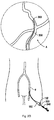
- a guide catheter 150 discussed in conjunction with the method of use below can also have a side arm 152 for injection of fluid (see Figure 2D ).
- the side arm 152 is also used for aspiration by system 10.
- a RHV 170 with a side arm 172 can be used with a guide catheter 150 (which does not have a side arm) as shown in Figure 2A .
- Actuation of the pump aspirates particles through the space between the introducer catheter 300 and guide catheter 150, into tubing 98 and long tube 105 and into the chamber 55 where it is outputted via tubes 70 and 80 into the collection bag 21.
- the RHV does not have a side arm.
- a guide catheter with a side arm can be used for injection and suction.
- the guide catheter with a side arm can also be used in conjunction with an RHV with a side arm so that suction can occur through the RHV and neuro catheter and/or through the guide catheter. This is shown in Figure 2D .
- the tubular portion 262 of introducer sheath 260 extends through the lumen of RHV 240 and terminates either within RHV 240 or at a proximal portion of the lumen of the introducer catheter 300.
- the tubular portion 262 preferably has a stiffness greater than the stiffness of the thrombectomy wire 230 to maintain the wire 230 in a straightened position during passage of wire 230 into the RHV 240 for subsequent passage through the lumen of the introducer catheter 300 to the surgical site.
- Proximal end 265 of introducer sheath 260 is attachable to connector tube 280.
- the enlarged proximal end 265 has a threaded flange to threadingly engage the internal threads on the tubular connector 280.
- a valve can be provided within the distal end 282 of the connector tube 280 in addition or instead of a valve in a proximal end 265 of the introducer sheath 260 to seal escape of fluid to improve the vacuum through the side arm 256.
- tube 280 and introducer sheath 260 can alternatively be provided as one unit, attached together and positioned over the thrombectomy wire 230 as an attached unit.
- the wire 230 is inserted through the introducer sheath 260 and manipulated through the introducer catheter 300 to the surgical site.
- the connector tube 280 is then threadingly attached at the distal end 282 to the introducer sheath 260 as noted above and at a proximal end 284 to the motor housing 212.
- the connector tube 280 can be positioned over the wire 230 prior to insertion of the wire 230 through introducer sheath 260 or after insertion through the sheath 260.
- the wire 230 can be packaged with the sheath 260 and the tube 280 positioned thereover, or packaged apart from the sheath 260 and tube 280.
- Proximal end 284 of connector tube 280 is configured for attachment to the motor housing 212.
- a ring is seated within an internal groove of connector tube 280 to provide a snap fit.
- proximal end of the wire 230 is attached to the drive shaft 215 of the motor 214.
- end cap 231 of wire 230 is snap fit within opening 215a in motor shaft 215.
- Other ways to attach the wire 230 and motor shaft 215 are also contemplated such as a bayonet mount for example or a magnetic coupler wherein a magnet is attached to wire 230 and mates with a magnet attached to the motor housing.
- the housing can be detached, sterilized and reused after recharging of the battery or replacing the battery.
- the proximal end of wire 230 after insertion to the surgical site or prior to insertion, can be attached at a proximal end to a coupler tube which is connected to a gear reducer.
- the connection can be a friction fit, a magnetic coupling or a twist connect, e.g., a bayonet connection, by way of example.
- the wire 230 has a distal coiled tip angled with respect to the longitudinal axis.
- Figure 2A shows the wire forming a sinuous shape.
- the wire forms a J-tip which creates a standing wave upon rotation. In the J-tip configuration, due to the angle, when the wire is rotated by the motor at sufficient speed at least one vibrational node is formed. Details of this creation of a standing wave are described in U.S. Patent No. 6,090,118 .
- the wire 230 forms a substantially sinuous shape, resembling a sine curve. More specifically, wire 230 has a substantially linear portion extending through most of its length, from a proximal region, through an intermediate region, to a distal region. At the distal region 236, wire 230 has a sinuous shape in that as shown it has a first arcuate region 233 facing a first direction (upwardly as viewed in the orientation of Figure 2A ) and a second arcuate region 235, spaced longitudinally from the first arcuate region 233, facing a second opposite direction (downwardly as viewed in the orientation of Figure 2A ). These arcuate regions 233, 235 form "peaks" to contact vascular structure as the wire 230 rotates.
- This angled (non-linear) distal portion of wire 230 can include a coiled portion with a covering material to block the interstices of the coil.
- the amplitude of the proximal wave (at region 233) is smaller than the amplitude of the distal wave (at region 235), facilitating movement in and out of the catheter.
- the curved regions of the wire 230 are compressed so the distal region is contained in a substantially straight or substantially linear non-deployed configuration.
- the introducer catheter 300 (attached to RHV 240) is retracted by proximal axial movement, or the wire 230 is advanced with respect to the introducer catheter 300, or the wire 230 and catheter 300 are both moved in the respective distal and proximal directions, the distal region of the wire 230 is exposed to enable the wire 230 to return to its non-linear substantially sinuous configuration for rotation about its longitudinal axis within the lumen of the vessel.
- the wire 230 is advanced within the introducer catheter 300 which is attached at its proximal end to the distal end of the RHV 240.
- the wire 230 and introducer catheter 300 are relatively moved to expose the wire 230 to assume its non-linear shape for motorized rotational movement to break up thrombotic material on the vessel wall. If a J-tip wire is utilized, the wire can be rotated within the introducer catheter 300 to re-orient the wire.
- the flexible tubular portion 262 of the introducer sheath 300 can optionally contain one or more braided wires embedded in the wall to increase the stiffness. Such braided wires would preferably extend the length of the sheath 300.
- the memorized configuration is sinuous or s-shape as in Figure 2A .
- the wire In the state within the introducer catheter 300, the wire is in a substantially linear configuration. This state is used for delivering the wire to the surgical site. When the wire is exposed to warmer body temperature, the tip transforms to its austenitic state, assuming the s-shaped memorized configuration.
- the coiled tip of the wire can be compressed within the wall of the introducer catheter and when released, assumes its shape memorized non-linear shape.
- the coiled tip can alternatively be a radiopaque coil/polymer pre-shaped to an "S".
- An access sheath (not shown) is inserted into the vessel and then a guidewire e.g. 0.89 or 0.97 mm (.035 or .038 inches) in diameter, and a guide catheter 150' are inserted through the sheath and advanced through the vasculature.
- the guide catheter 150' has a side arm 152 for aspiration.
- a guide catheter without a side arm can be utilized in conjunction with a RHV with a side arm for aspiration as in the embodiment of Figure 2A .
- the guidewire is removed and a smaller diameter guidewire, e.g. 0.36 mm (.014 inch) diameter, and the introducer catheter 300 are inserted through the guide catheter 150' and access sheath with the guidewire G in the femoral artery F and located via imaging.
- the introducer catheter 300 is advanced to the desired site through the vascular system into the cerebral arteries A, for example through the Circle of Willis (see Figure 2D ). Once at the site, the guidewire is withdrawn.
- the introducer catheter 300 is preferably inserted with the RHV 240 attached. That is, the tubular portion 246 of the RHV 240 is inserted through the introducer catheter 300 and attached thereto by rotation of cap 251.
- RHV 240 instead of the RHV 240 attached prior to introduction of the introducer catheter 300 through the guide catheter, it can be attached after introduction of catheter 300 through the guide catheter.
- the introducer sheath 260 is inserted through the RHV 240, and attached to the RHV 240 by rotation of cap 258 as shown in Figure 2C .
- the thrombectomy wire 230 is inserted through the lumen of the introducer sheath 260, through the lumen of the RHV 240 and into the lumen of the introducer catheter 300.
- the introducer catheter 300 extends from the guide catheter 150' as shown in Figure 2D , but the wire 230 remains inside the introducer catheter 300. The distal end of the wire 230 is then exposed from the introducer catheter 300 at the target surgical site by relative movement of the wire and introducer sheath 300.
- the wire 230 can be attached to the motor drive shaft 215 at this point or can be attached before exposed or at any other time in the procedure such as prior to insertion of the wire 230 through the introducer sheath 260. Attachment is achieved by connection of the connector tube 280 to the introducer sheath 260 and attachment of the proximal end of the connector 280 to the motor housing 212. The wire 230 extends through the connector tube and extends through connector 280 to the motor drive shaft 215. As noted above, alternatively, the connector tube 280 can be connected to the introducer sheath 260 prior to attachment to the motor housing 212, or alternatively connected after the wire 230 is at the surgical site and exposed from the introducer sheath.
- switch 219 on housing 122 is actuated to turn on the motor 214 thereby causing wire 230 to rotate about its longitudinal axis to break up/macerate thrombus.
- the pump 54 is turned on by switch 16. This aspirates the macerated particles through side arm 256 of RHV 240 as the particles travel in the space between wire 230 and introducer catheter 300 and RHV 240. Larger particles can be aspirated through the space between the guide catheter 150 (or 150') and introducer catheter 300. Aspirated particles travel through the respective RHV sides ports, into the respective tubing and into chamber 55. The pump 54 further pumps the aspirated particles from chamber 55 through the bag tubing 80 and into collection bag 21 as described above.
- Note introducer catheter 300 can optionally have a side port(s) and/or the guide catheter 150 can optionally have a side port(s) such as side port 152 for aspirating the small macerated particles in addition to or as an alternative to a side arm of an RHV.
- the delivery (access) sheath or delivery catheter can optionally include a balloon (not shown) to block blood flow and allow aspiration in the blocked space.
Landscapes
- Health & Medical Sciences (AREA)
- Heart & Thoracic Surgery (AREA)
- Life Sciences & Earth Sciences (AREA)
- Animal Behavior & Ethology (AREA)
- General Health & Medical Sciences (AREA)
- Engineering & Computer Science (AREA)
- Biomedical Technology (AREA)
- Veterinary Medicine (AREA)
- Public Health (AREA)
- Surgery (AREA)
- Hematology (AREA)
- Anesthesiology (AREA)
- Vascular Medicine (AREA)
- Pulmonology (AREA)
- Molecular Biology (AREA)
- Medical Informatics (AREA)
- Nuclear Medicine, Radiotherapy & Molecular Imaging (AREA)
- Orthopedic Medicine & Surgery (AREA)
- Biophysics (AREA)
- Surgical Instruments (AREA)
- External Artificial Organs (AREA)
Applications Claiming Priority (2)
| Application Number | Priority Date | Filing Date | Title |
|---|---|---|---|
| US201361916034P | 2013-12-13 | 2013-12-13 | |
| US14/550,941 US10219814B2 (en) | 2013-12-13 | 2014-11-22 | Aspiration system for thrombectomy procedures |
Publications (2)
| Publication Number | Publication Date |
|---|---|
| EP2883556A1 EP2883556A1 (en) | 2015-06-17 |
| EP2883556B1 true EP2883556B1 (en) | 2016-08-24 |
Family
ID=52021041
Family Applications (1)
| Application Number | Title | Priority Date | Filing Date |
|---|---|---|---|
| EP14196918.8A Not-in-force EP2883556B1 (en) | 2013-12-13 | 2014-12-09 | Aspiration system for thrombectomy procedures |
Country Status (3)
| Country | Link |
|---|---|
| US (3) | US10219814B2 (enExample) |
| EP (1) | EP2883556B1 (enExample) |
| JP (1) | JP6906886B2 (enExample) |
Families Citing this family (24)
| Publication number | Priority date | Publication date | Assignee | Title |
|---|---|---|---|---|
| US10183145B2 (en) | 2016-02-24 | 2019-01-22 | Incept, Llc | Enhanced flexibility neurovascular catheter |
| USD802769S1 (en) | 2016-05-16 | 2017-11-14 | Teleflex Medical Incorporated | Thrombectomy handle assembly |
| KR102687413B1 (ko) * | 2017-03-20 | 2024-07-24 | 퍼넘브러, 인코퍼레이티드 | 두개 내 출혈의 제거 방법 및 장치 |
| WO2019212984A1 (en) | 2018-05-01 | 2019-11-07 | Imperative Care, Inc. | Devices and methods for removing obstructive material from an intravascular site |
| US11471582B2 (en) | 2018-07-06 | 2022-10-18 | Incept, Llc | Vacuum transfer tool for extendable catheter |
| US11766539B2 (en) | 2019-03-29 | 2023-09-26 | Incept, Llc | Enhanced flexibility neurovascular catheter |
| WO2021127004A1 (en) | 2019-12-18 | 2021-06-24 | Imperative Care, Inc. | Methods and systems for treating venous thromboembolic disease |
| US20230248502A1 (en) | 2019-12-18 | 2023-08-10 | Imperative Care, Inc. | Sterile field clot capture module for use in thrombectomy system |
| US20210315598A1 (en) | 2019-12-18 | 2021-10-14 | Imperative Care, Inc. | Methods of placing large bore aspiration catheters |
| CN111956900B (zh) * | 2020-09-22 | 2021-04-09 | 浙江迈帝康医疗器械有限公司 | 一种多通道自动输液控制装置 |
| US20220330958A1 (en) * | 2021-04-19 | 2022-10-20 | Argon Medical Devices, Inc. | Disposable thrombectomy maceration and aspiration system |
| US11679194B2 (en) | 2021-04-27 | 2023-06-20 | Contego Medical, Inc. | Thrombus aspiration system and methods for controlling blood loss |
| US12447317B2 (en) | 2022-08-01 | 2025-10-21 | Imperative Care, Inc. | Method of priming concentrically stacked interventional devices |
| US12446979B2 (en) | 2022-08-01 | 2025-10-21 | Imperative Care, Inc. | Method of performing a multi catheter robotic neurovascular procedure |
| US12440289B2 (en) | 2022-08-01 | 2025-10-14 | Imperative Care, Inc. | Method of priming an interventional device assembly |
| US12419703B2 (en) | 2022-08-01 | 2025-09-23 | Imperative Care, Inc. | Robotic drive system for achieving supra-aortic access |
| US20230047098A1 (en) | 2021-08-12 | 2023-02-16 | Imperative Care, Inc. | Multi catheter method of performing a robotic neurovascular procedure |
| US12220139B2 (en) | 2022-03-20 | 2025-02-11 | Von Vascular, Inc. | System, devices and methods for removing obstructions in body lumens |
| US20240041480A1 (en) | 2022-08-02 | 2024-02-08 | Imperative Care, Inc. | Multi catheter system with integrated fluidics management |
| CN120529878A (zh) | 2022-12-01 | 2025-08-22 | 因普瑞缇夫护理公司 | 伸缩驱动台及使用方法 |
| EP4637502A2 (en) * | 2022-12-20 | 2025-10-29 | Imperative Care, Inc. | Systems and methods of performing a robotic and manual vascular procedure |
| US12377206B2 (en) | 2023-05-17 | 2025-08-05 | Imperative Care, Inc. | Fluidics control system for multi catheter stack |
| USD1102447S1 (en) | 2023-11-30 | 2025-11-18 | Imperative Care, Inc. | Display screen or portion thereof with graphical user interface |
| US12171917B1 (en) | 2024-01-08 | 2024-12-24 | Imperative Care, Inc. | Devices for blood capture and reintroduction during aspiration procedure |
Family Cites Families (76)
| Publication number | Priority date | Publication date | Assignee | Title |
|---|---|---|---|---|
| US4029097A (en) * | 1975-07-25 | 1977-06-14 | New Research And Development Laboratories, Inc. | Surgical sponge collector and drainage system |
| US4324243A (en) | 1979-11-28 | 1982-04-13 | Helfgott Maxwell A | Apparatus and process for aspirating and evacuating a surgical site |
| US4504263A (en) * | 1982-12-22 | 1985-03-12 | Valleylab, Inc. | Flow rate monitor with optical sensing chamber |
| JPS60135136U (ja) * | 1984-02-17 | 1985-09-07 | 浪華ゴム工業株式会社 | 血液回路 |
| US4750902A (en) | 1985-08-28 | 1988-06-14 | Sonomed Technology, Inc. | Endoscopic ultrasonic aspirators |
| US4883476A (en) | 1988-01-07 | 1989-11-28 | Bioresearch, Inc. | Drainage device with disposable collection chamber |
| US5176502A (en) | 1990-04-25 | 1993-01-05 | Becton, Dickinson And Company | Syringe pump and the like for delivering medication |
| US5078683A (en) | 1990-05-04 | 1992-01-07 | Block Medical, Inc. | Programmable infusion system |
| US5273526A (en) | 1991-06-21 | 1993-12-28 | Lake Region Manufacturing Company, Inc. | Vascular occulusion removal devices and method |
| WO1993019679A1 (en) | 1992-04-07 | 1993-10-14 | The Johns Hopkins University | A percutaneous mechanical fragmentation catheter system |
| BR9305912A (pt) | 1992-12-18 | 1997-08-19 | Amoco Corp | Processo para a produção de olefinas em uma planta de olefinas |
| US5462529A (en) | 1993-09-29 | 1995-10-31 | Technology Development Center | Adjustable treatment chamber catheter |
| US6652495B1 (en) | 1995-04-10 | 2003-11-25 | Kenneth Gordon Walker | System for disposal of fluids |
| US5662627A (en) | 1995-08-09 | 1997-09-02 | Sscor, Inc. | Aspiration apparatus |
| US6080170A (en) | 1996-07-26 | 2000-06-27 | Kensey Nash Corporation | System and method of use for revascularizing stenotic bypass grafts and other occluded blood vessels |
| US5779721A (en) | 1996-07-26 | 1998-07-14 | Kensey Nash Corporation | System and method of use for revascularizing stenotic bypass grafts and other blood vessels |
| US6905505B2 (en) | 1996-07-26 | 2005-06-14 | Kensey Nash Corporation | System and method of use for agent delivery and revascularizing of grafts and vessels |
| WO1998034673A1 (en) * | 1997-02-12 | 1998-08-13 | Prolifix Medical, Inc. | Apparatus for removal of material from stents |
| US5843103A (en) | 1997-03-06 | 1998-12-01 | Scimed Life Systems, Inc. | Shaped wire rotational atherectomy device |
| US7037316B2 (en) | 1997-07-24 | 2006-05-02 | Mcguckin Jr James F | Rotational thrombectomy device |
| US6090118A (en) | 1998-07-23 | 2000-07-18 | Mcguckin, Jr.; James F. | Rotational thrombectomy apparatus and method with standing wave |
| US6758851B2 (en) | 1999-02-02 | 2004-07-06 | Samuel Shiber | Vessel cleaner |
| US6423035B1 (en) | 1999-06-18 | 2002-07-23 | Animas Corporation | Infusion pump with a sealed drive mechanism and improved method of occlusion detection |
| US6352525B1 (en) | 1999-09-22 | 2002-03-05 | Akio Wakabayashi | Portable modular chest drainage system |
| ES2267437T3 (es) | 2000-08-28 | 2007-03-16 | Medela Ag | Una bomba de aspiracion. |
| JP2005518875A (ja) | 2002-02-28 | 2005-06-30 | セイ ファミリー トラスト | 携帯可能な電池作動式吸入器 |
| JP2004049704A (ja) | 2002-07-23 | 2004-02-19 | Nipro Corp | 医療用吸引器 |
| US7998107B2 (en) | 2002-09-24 | 2011-08-16 | Kensey Nash Corporation | Interventional procedure drive and control system |
| US20040230136A1 (en) * | 2003-05-14 | 2004-11-18 | Corrigan Richard F. | Guidewire having axially extending flow through passageways |
| US7753588B2 (en) * | 2003-09-15 | 2010-07-13 | Superbag Corp. | Bag, bag pack, and bag dispensing system |
| US20050065471A1 (en) * | 2003-09-23 | 2005-03-24 | Charles Kuntz | Continuous safe suction device |
| US7959608B2 (en) | 2004-04-27 | 2011-06-14 | The Spectranetics Corporation | Thrombectomy and soft debris removal device |
| US7736354B2 (en) * | 2004-09-09 | 2010-06-15 | Plc Medical Systems, Inc. | Patient hydration system with hydration state detection |
| US7819887B2 (en) | 2004-11-17 | 2010-10-26 | Rex Medical, L.P. | Rotational thrombectomy wire |
| US7357142B2 (en) | 2004-12-31 | 2008-04-15 | Md Technologies Inc. | Apparatus for continuously aspirating a fluid from a fluid source |
| US7857806B2 (en) | 2005-07-14 | 2010-12-28 | Boehringer Technologies, L.P. | Pump system for negative pressure wound therapy |
| US7935077B2 (en) | 2005-09-28 | 2011-05-03 | Medrad, Inc. | Thrombectomy catheter deployment system |
| SG171663A1 (en) | 2006-05-09 | 2011-06-29 | Medela Holding Ag | Aspiration pump unit |
| US8529530B2 (en) | 2006-05-09 | 2013-09-10 | Medela Holding Ag | Drainage pump unit |
| JP4238257B2 (ja) | 2006-06-28 | 2009-03-18 | 株式会社日立製作所 | 自動収尿装置 |
| JP4749969B2 (ja) | 2006-08-01 | 2011-08-17 | 株式会社ニデック | 灌流吸引装置 |
| US7967810B2 (en) | 2006-10-20 | 2011-06-28 | Mary Beth Kelley | Sub-atmospheric wound-care system |
| US8414534B2 (en) | 2006-11-09 | 2013-04-09 | Abbott Medical Optics Inc. | Holding tank devices, systems, and methods for surgical fluidics cassette |
| US8430837B2 (en) | 2007-02-05 | 2013-04-30 | Boston Scientific Scimed, Inc. | Thrombectomy apparatus and method |
| US8500706B2 (en) | 2007-03-23 | 2013-08-06 | Allegiance Corporation | Fluid collection and disposal system having interchangeable collection and other features and methods relating thereto |
| ES2621976T3 (es) | 2007-04-20 | 2017-07-05 | Doheny Eye Institute | Centro quirúrgico independiente |
| US8491550B2 (en) | 2007-05-22 | 2013-07-23 | Medela Holding Ag | Drainage tube unit |
| GB0712760D0 (en) | 2007-07-02 | 2007-08-08 | Smith & Nephew | Status indication |
| GB0712736D0 (en) | 2007-07-02 | 2007-08-08 | Smith & Nephew | Apparatus |
| GB0715211D0 (en) | 2007-08-06 | 2007-09-12 | Smith & Nephew | Apparatus |
| GB0712764D0 (en) | 2007-07-02 | 2007-08-08 | Smith & Nephew | Carrying Bag |
| USD602584S1 (en) | 2007-07-02 | 2009-10-20 | Smith & Nephew Plc | Canister |
| USD602582S1 (en) | 2007-07-02 | 2009-10-20 | Smith & Nephew LLC | Therapy unit assembly |
| GB0715212D0 (en) | 2007-08-06 | 2007-09-12 | Smith & Nephew | Apparatus |
| GB0722990D0 (en) | 2007-11-23 | 2008-01-02 | Shturman Leonid | Rotational atherectomy system with enhanced distal protection capability and method of use |
| GB0723855D0 (en) | 2007-12-06 | 2008-01-16 | Smith & Nephew | Apparatus and method for wound volume measurement |
| GB0724564D0 (en) | 2007-12-18 | 2008-01-30 | Smith & Nephew | Portable wound therapy apparatus and method |
| US8579851B2 (en) | 2007-12-20 | 2013-11-12 | Bausch & Lomb Incorporated | Surgical system having means for isolating vacuum pump |
| US8414478B2 (en) | 2008-02-26 | 2013-04-09 | Fujifilm Corporation | Endoscopic aspiration device |
| JP5241337B2 (ja) * | 2008-06-12 | 2013-07-17 | 日機装株式会社 | ローラポンプ及びローラポンプを備えた血液浄化装置 |
| US8262616B2 (en) | 2008-10-10 | 2012-09-11 | Deka Products Limited Partnership | Infusion pump assembly |
| US9072540B2 (en) | 2009-08-12 | 2015-07-07 | Boston Scientific Limited | Adaptive tubing cassettes for use in connection with interventional catheter assemblies |
| CH702195A1 (de) | 2009-11-05 | 2011-05-13 | Medela Holding Ag | Drainagepumpeinheit |
| USD645137S1 (en) | 2009-12-04 | 2011-09-13 | Smith & Nephew Plc | Canister |
| US8764779B2 (en) | 2010-05-13 | 2014-07-01 | Rex Medical, L.P. | Rotational thrombectomy wire |
| US8663259B2 (en) | 2010-05-13 | 2014-03-04 | Rex Medical L.P. | Rotational thrombectomy wire |
| US8409160B2 (en) | 2010-05-18 | 2013-04-02 | Kci Licensing, Inc. | Reduced-pressure treatment systems and methods employing a fluidly isolated pump control unit |
| GB201015656D0 (en) | 2010-09-20 | 2010-10-27 | Smith & Nephew | Pressure control apparatus |
| RU2586738C2 (ru) | 2010-12-16 | 2016-06-10 | Алькон Рисерч, Лтд. | Системы и способы аспирации с трубками малого диаметра |
| GR20110100184A (el) | 2011-03-28 | 2012-09-15 | Αχιλλεας Τσουκαλης | Συστημα ανταλλαγης υγρων για ιατρικη χρηση |
| CA2874443A1 (en) | 2011-05-13 | 2012-11-22 | Vascular Technology Inc. | Remotely controlled suction/irrigation for surgery |
| US10327790B2 (en) * | 2011-08-05 | 2019-06-25 | Route 92 Medical, Inc. | Methods and systems for treatment of acute ischemic stroke |
| MX355633B (es) * | 2012-01-19 | 2018-04-25 | Baxter Int | Método y composición para eliminar las toxinas urémicas en los procesos de diálisis. |
| US9427505B2 (en) * | 2012-05-15 | 2016-08-30 | Smith & Nephew Plc | Negative pressure wound therapy apparatus |
| US9138514B2 (en) * | 2012-06-12 | 2015-09-22 | H. George Brennan | Medical suction system and disposable container |
| US9315099B2 (en) * | 2012-08-01 | 2016-04-19 | Brunswick Corporation | Fuel fill apparatus for use with fuel tanks |
-
2014
- 2014-11-22 US US14/550,941 patent/US10219814B2/en active Active
- 2014-12-09 EP EP14196918.8A patent/EP2883556B1/en not_active Not-in-force
- 2014-12-12 JP JP2014252225A patent/JP6906886B2/ja not_active Expired - Fee Related
-
2017
- 2017-04-07 US US15/482,662 patent/US10772644B2/en not_active Expired - Fee Related
-
2020
- 2020-09-04 US US17/012,894 patent/US20200397451A1/en not_active Abandoned
Also Published As
| Publication number | Publication date |
|---|---|
| EP2883556A1 (en) | 2015-06-17 |
| US10219814B2 (en) | 2019-03-05 |
| US10772644B2 (en) | 2020-09-15 |
| JP6906886B2 (ja) | 2021-07-21 |
| US20150165100A1 (en) | 2015-06-18 |
| US20200397451A1 (en) | 2020-12-24 |
| JP2015112497A (ja) | 2015-06-22 |
| US20170209161A1 (en) | 2017-07-27 |
Similar Documents
| Publication | Publication Date | Title |
|---|---|---|
| EP2883556B1 (en) | Aspiration system for thrombectomy procedures | |
| US10869956B2 (en) | Interventional catheters incorporating aspiration and/or infusion systems | |
| US10149698B2 (en) | Interventional catheter assemblies, control systems and operating methods | |
| US8394078B2 (en) | Interventional catheters incorporating an active aspiration system | |
| US7918822B2 (en) | Surgical aspiration system and method of surgical aspiration | |
| US7018354B2 (en) | Liposuction devices and methods and surrounding aspiration systems and methods | |
| US20040243162A1 (en) | Interventional catheter assemblies and control systems | |
| US20070239182A1 (en) | Thrombus removal device | |
| WO2004080507A2 (en) | Interventional catheters assemblies and control systems | |
| AU2002348853A1 (en) | Liposuction devices and methods and surrounding aspiration systems and methods | |
| US20190365469A1 (en) | Laser device for vascular and intrabody surgery and method of use | |
| EP3979939A1 (en) | Laser device for vascular and intrabody surgery and method of use | |
| AU2013205920A1 (en) | Interventional catheters | |
| CN116999158A (zh) | 一种3部件多方式组合使用的清石鞘套件 | |
| US20250352225A1 (en) | Aspiration systems, devices and methods for treating ischemic stroke | |
| JPH0554986B2 (enExample) |
Legal Events
| Date | Code | Title | Description |
|---|---|---|---|
| PUAI | Public reference made under article 153(3) epc to a published international application that has entered the european phase |
Free format text: ORIGINAL CODE: 0009012 |
|
| 17P | Request for examination filed |
Effective date: 20141209 |
|
| AK | Designated contracting states |
Kind code of ref document: A1 Designated state(s): AL AT BE BG CH CY CZ DE DK EE ES FI FR GB GR HR HU IE IS IT LI LT LU LV MC MK MT NL NO PL PT RO RS SE SI SK SM TR |
|
| AX | Request for extension of the european patent |
Extension state: BA ME |
|
| R17P | Request for examination filed (corrected) |
Effective date: 20151216 |
|
| RBV | Designated contracting states (corrected) |
Designated state(s): AL AT BE BG CH CY CZ DE DK EE ES FI FR GB GR HR HU IE IS IT LI LT LU LV MC MK MT NL NO PL PT RO RS SE SI SK SM TR |
|
| RIC1 | Information provided on ipc code assigned before grant |
Ipc: A61M 1/00 20060101AFI20160120BHEP Ipc: A61B 17/3207 20060101ALI20160120BHEP |
|
| GRAP | Despatch of communication of intention to grant a patent |
Free format text: ORIGINAL CODE: EPIDOSNIGR1 |
|
| INTG | Intention to grant announced |
Effective date: 20160404 |
|
| GRAS | Grant fee paid |
Free format text: ORIGINAL CODE: EPIDOSNIGR3 |
|
| GRAA | (expected) grant |
Free format text: ORIGINAL CODE: 0009210 |
|
| AK | Designated contracting states |
Kind code of ref document: B1 Designated state(s): AL AT BE BG CH CY CZ DE DK EE ES FI FR GB GR HR HU IE IS IT LI LT LU LV MC MK MT NL NO PL PT RO RS SE SI SK SM TR |
|
| REG | Reference to a national code |
Ref country code: GB Ref legal event code: FG4D |
|
| REG | Reference to a national code |
Ref country code: CH Ref legal event code: EP |
|
| REG | Reference to a national code |
Ref country code: AT Ref legal event code: REF Ref document number: 822490 Country of ref document: AT Kind code of ref document: T Effective date: 20160915 |
|
| REG | Reference to a national code |
Ref country code: IE Ref legal event code: FG4D |
|
| REG | Reference to a national code |
Ref country code: DE Ref legal event code: R096 Ref document number: 602014003265 Country of ref document: DE |
|
| REG | Reference to a national code |
Ref country code: LT Ref legal event code: MG4D |
|
| REG | Reference to a national code |
Ref country code: NL Ref legal event code: MP Effective date: 20160824 |
|
| REG | Reference to a national code |
Ref country code: AT Ref legal event code: MK05 Ref document number: 822490 Country of ref document: AT Kind code of ref document: T Effective date: 20160824 |
|
| PG25 | Lapsed in a contracting state [announced via postgrant information from national office to epo] |
Ref country code: IT Free format text: LAPSE BECAUSE OF FAILURE TO SUBMIT A TRANSLATION OF THE DESCRIPTION OR TO PAY THE FEE WITHIN THE PRESCRIBED TIME-LIMIT Effective date: 20160824 Ref country code: NL Free format text: LAPSE BECAUSE OF FAILURE TO SUBMIT A TRANSLATION OF THE DESCRIPTION OR TO PAY THE FEE WITHIN THE PRESCRIBED TIME-LIMIT Effective date: 20160824 Ref country code: RS Free format text: LAPSE BECAUSE OF FAILURE TO SUBMIT A TRANSLATION OF THE DESCRIPTION OR TO PAY THE FEE WITHIN THE PRESCRIBED TIME-LIMIT Effective date: 20160824 Ref country code: LT Free format text: LAPSE BECAUSE OF FAILURE TO SUBMIT A TRANSLATION OF THE DESCRIPTION OR TO PAY THE FEE WITHIN THE PRESCRIBED TIME-LIMIT Effective date: 20160824 Ref country code: HR Free format text: LAPSE BECAUSE OF FAILURE TO SUBMIT A TRANSLATION OF THE DESCRIPTION OR TO PAY THE FEE WITHIN THE PRESCRIBED TIME-LIMIT Effective date: 20160824 Ref country code: FI Free format text: LAPSE BECAUSE OF FAILURE TO SUBMIT A TRANSLATION OF THE DESCRIPTION OR TO PAY THE FEE WITHIN THE PRESCRIBED TIME-LIMIT Effective date: 20160824 Ref country code: NO Free format text: LAPSE BECAUSE OF FAILURE TO SUBMIT A TRANSLATION OF THE DESCRIPTION OR TO PAY THE FEE WITHIN THE PRESCRIBED TIME-LIMIT Effective date: 20161124 |
|
| PG25 | Lapsed in a contracting state [announced via postgrant information from national office to epo] |
Ref country code: SE Free format text: LAPSE BECAUSE OF FAILURE TO SUBMIT A TRANSLATION OF THE DESCRIPTION OR TO PAY THE FEE WITHIN THE PRESCRIBED TIME-LIMIT Effective date: 20160824 Ref country code: ES Free format text: LAPSE BECAUSE OF FAILURE TO SUBMIT A TRANSLATION OF THE DESCRIPTION OR TO PAY THE FEE WITHIN THE PRESCRIBED TIME-LIMIT Effective date: 20160824 Ref country code: LV Free format text: LAPSE BECAUSE OF FAILURE TO SUBMIT A TRANSLATION OF THE DESCRIPTION OR TO PAY THE FEE WITHIN THE PRESCRIBED TIME-LIMIT Effective date: 20160824 Ref country code: GR Free format text: LAPSE BECAUSE OF FAILURE TO SUBMIT A TRANSLATION OF THE DESCRIPTION OR TO PAY THE FEE WITHIN THE PRESCRIBED TIME-LIMIT Effective date: 20161125 Ref country code: PT Free format text: LAPSE BECAUSE OF FAILURE TO SUBMIT A TRANSLATION OF THE DESCRIPTION OR TO PAY THE FEE WITHIN THE PRESCRIBED TIME-LIMIT Effective date: 20161226 Ref country code: AT Free format text: LAPSE BECAUSE OF FAILURE TO SUBMIT A TRANSLATION OF THE DESCRIPTION OR TO PAY THE FEE WITHIN THE PRESCRIBED TIME-LIMIT Effective date: 20160824 |
|
| PG25 | Lapsed in a contracting state [announced via postgrant information from national office to epo] |
Ref country code: EE Free format text: LAPSE BECAUSE OF FAILURE TO SUBMIT A TRANSLATION OF THE DESCRIPTION OR TO PAY THE FEE WITHIN THE PRESCRIBED TIME-LIMIT Effective date: 20160824 Ref country code: RO Free format text: LAPSE BECAUSE OF FAILURE TO SUBMIT A TRANSLATION OF THE DESCRIPTION OR TO PAY THE FEE WITHIN THE PRESCRIBED TIME-LIMIT Effective date: 20160824 |
|
| REG | Reference to a national code |
Ref country code: DE Ref legal event code: R097 Ref document number: 602014003265 Country of ref document: DE |
|
| PG25 | Lapsed in a contracting state [announced via postgrant information from national office to epo] |
Ref country code: DK Free format text: LAPSE BECAUSE OF FAILURE TO SUBMIT A TRANSLATION OF THE DESCRIPTION OR TO PAY THE FEE WITHIN THE PRESCRIBED TIME-LIMIT Effective date: 20160824 Ref country code: BG Free format text: LAPSE BECAUSE OF FAILURE TO SUBMIT A TRANSLATION OF THE DESCRIPTION OR TO PAY THE FEE WITHIN THE PRESCRIBED TIME-LIMIT Effective date: 20161124 Ref country code: CZ Free format text: LAPSE BECAUSE OF FAILURE TO SUBMIT A TRANSLATION OF THE DESCRIPTION OR TO PAY THE FEE WITHIN THE PRESCRIBED TIME-LIMIT Effective date: 20160824 Ref country code: SK Free format text: LAPSE BECAUSE OF FAILURE TO SUBMIT A TRANSLATION OF THE DESCRIPTION OR TO PAY THE FEE WITHIN THE PRESCRIBED TIME-LIMIT Effective date: 20160824 Ref country code: PL Free format text: LAPSE BECAUSE OF FAILURE TO SUBMIT A TRANSLATION OF THE DESCRIPTION OR TO PAY THE FEE WITHIN THE PRESCRIBED TIME-LIMIT Effective date: 20160824 Ref country code: SM Free format text: LAPSE BECAUSE OF FAILURE TO SUBMIT A TRANSLATION OF THE DESCRIPTION OR TO PAY THE FEE WITHIN THE PRESCRIBED TIME-LIMIT Effective date: 20160824 Ref country code: BE Free format text: LAPSE BECAUSE OF FAILURE TO SUBMIT A TRANSLATION OF THE DESCRIPTION OR TO PAY THE FEE WITHIN THE PRESCRIBED TIME-LIMIT Effective date: 20160824 |
|
| PLBE | No opposition filed within time limit |
Free format text: ORIGINAL CODE: 0009261 |
|
| STAA | Information on the status of an ep patent application or granted ep patent |
Free format text: STATUS: NO OPPOSITION FILED WITHIN TIME LIMIT |
|
| 26N | No opposition filed |
Effective date: 20170526 |
|
| PG25 | Lapsed in a contracting state [announced via postgrant information from national office to epo] |
Ref country code: SI Free format text: LAPSE BECAUSE OF FAILURE TO SUBMIT A TRANSLATION OF THE DESCRIPTION OR TO PAY THE FEE WITHIN THE PRESCRIBED TIME-LIMIT Effective date: 20160824 |
|
| PG25 | Lapsed in a contracting state [announced via postgrant information from national office to epo] |
Ref country code: MC Free format text: LAPSE BECAUSE OF FAILURE TO SUBMIT A TRANSLATION OF THE DESCRIPTION OR TO PAY THE FEE WITHIN THE PRESCRIBED TIME-LIMIT Effective date: 20160824 |
|
| REG | Reference to a national code |
Ref country code: FR Ref legal event code: ST Effective date: 20170831 |
|
| REG | Reference to a national code |
Ref country code: IE Ref legal event code: MM4A |
|
| PG25 | Lapsed in a contracting state [announced via postgrant information from national office to epo] |
Ref country code: LU Free format text: LAPSE BECAUSE OF NON-PAYMENT OF DUE FEES Effective date: 20161209 Ref country code: FR Free format text: LAPSE BECAUSE OF NON-PAYMENT OF DUE FEES Effective date: 20170102 |
|
| PG25 | Lapsed in a contracting state [announced via postgrant information from national office to epo] |
Ref country code: IE Free format text: LAPSE BECAUSE OF NON-PAYMENT OF DUE FEES Effective date: 20161209 |
|
| PG25 | Lapsed in a contracting state [announced via postgrant information from national office to epo] |
Ref country code: HU Free format text: LAPSE BECAUSE OF FAILURE TO SUBMIT A TRANSLATION OF THE DESCRIPTION OR TO PAY THE FEE WITHIN THE PRESCRIBED TIME-LIMIT; INVALID AB INITIO Effective date: 20141209 |
|
| PG25 | Lapsed in a contracting state [announced via postgrant information from national office to epo] |
Ref country code: CY Free format text: LAPSE BECAUSE OF FAILURE TO SUBMIT A TRANSLATION OF THE DESCRIPTION OR TO PAY THE FEE WITHIN THE PRESCRIBED TIME-LIMIT Effective date: 20160824 Ref country code: MK Free format text: LAPSE BECAUSE OF FAILURE TO SUBMIT A TRANSLATION OF THE DESCRIPTION OR TO PAY THE FEE WITHIN THE PRESCRIBED TIME-LIMIT Effective date: 20160824 Ref country code: IS Free format text: LAPSE BECAUSE OF FAILURE TO SUBMIT A TRANSLATION OF THE DESCRIPTION OR TO PAY THE FEE WITHIN THE PRESCRIBED TIME-LIMIT Effective date: 20160824 |
|
| REG | Reference to a national code |
Ref country code: CH Ref legal event code: PL |
|
| PG25 | Lapsed in a contracting state [announced via postgrant information from national office to epo] |
Ref country code: MT Free format text: LAPSE BECAUSE OF NON-PAYMENT OF DUE FEES Effective date: 20161209 |
|
| PG25 | Lapsed in a contracting state [announced via postgrant information from national office to epo] |
Ref country code: AL Free format text: LAPSE BECAUSE OF FAILURE TO SUBMIT A TRANSLATION OF THE DESCRIPTION OR TO PAY THE FEE WITHIN THE PRESCRIBED TIME-LIMIT Effective date: 20160824 Ref country code: TR Free format text: LAPSE BECAUSE OF FAILURE TO SUBMIT A TRANSLATION OF THE DESCRIPTION OR TO PAY THE FEE WITHIN THE PRESCRIBED TIME-LIMIT Effective date: 20160824 |
|
| PG25 | Lapsed in a contracting state [announced via postgrant information from national office to epo] |
Ref country code: CH Free format text: LAPSE BECAUSE OF NON-PAYMENT OF DUE FEES Effective date: 20171231 Ref country code: LI Free format text: LAPSE BECAUSE OF NON-PAYMENT OF DUE FEES Effective date: 20171231 |
|
| GBPC | Gb: european patent ceased through non-payment of renewal fee |
Effective date: 20181209 |
|
| PG25 | Lapsed in a contracting state [announced via postgrant information from national office to epo] |
Ref country code: GB Free format text: LAPSE BECAUSE OF NON-PAYMENT OF DUE FEES Effective date: 20181209 |
|
| PGFP | Annual fee paid to national office [announced via postgrant information from national office to epo] |
Ref country code: DE Payment date: 20211201 Year of fee payment: 8 |
|
| REG | Reference to a national code |
Ref country code: DE Ref legal event code: R119 Ref document number: 602014003265 Country of ref document: DE |
|
| PG25 | Lapsed in a contracting state [announced via postgrant information from national office to epo] |
Ref country code: DE Free format text: LAPSE BECAUSE OF NON-PAYMENT OF DUE FEES Effective date: 20230701 |