EP2883490A1 - Bio-optical measurement device, measurement probe, and bio-optical measurement system - Google Patents
Bio-optical measurement device, measurement probe, and bio-optical measurement system Download PDFInfo
- Publication number
- EP2883490A1 EP2883490A1 EP13879621.4A EP13879621A EP2883490A1 EP 2883490 A1 EP2883490 A1 EP 2883490A1 EP 13879621 A EP13879621 A EP 13879621A EP 2883490 A1 EP2883490 A1 EP 2883490A1
- Authority
- EP
- European Patent Office
- Prior art keywords
- unit
- connector unit
- optical measurement
- measurement probe
- connector
- Prior art date
- Legal status (The legal status is an assumption and is not a legal conclusion. Google has not performed a legal analysis and makes no representation as to the accuracy of the status listed.)
- Withdrawn
Links
Images






Classifications
-
- A—HUMAN NECESSITIES
- A61—MEDICAL OR VETERINARY SCIENCE; HYGIENE
- A61B—DIAGNOSIS; SURGERY; IDENTIFICATION
- A61B1/00—Instruments for performing medical examinations of the interior of cavities or tubes of the body by visual or photographical inspection, e.g. endoscopes; Illuminating arrangements therefor
- A61B1/00002—Operational features of endoscopes
- A61B1/00057—Operational features of endoscopes provided with means for testing or calibration
-
- A—HUMAN NECESSITIES
- A61—MEDICAL OR VETERINARY SCIENCE; HYGIENE
- A61B—DIAGNOSIS; SURGERY; IDENTIFICATION
- A61B1/00—Instruments for performing medical examinations of the interior of cavities or tubes of the body by visual or photographical inspection, e.g. endoscopes; Illuminating arrangements therefor
- A61B1/00147—Holding or positioning arrangements
- A61B1/00148—Holding or positioning arrangements using anchoring means
-
- A—HUMAN NECESSITIES
- A61—MEDICAL OR VETERINARY SCIENCE; HYGIENE
- A61B—DIAGNOSIS; SURGERY; IDENTIFICATION
- A61B5/00—Measuring for diagnostic purposes; Identification of persons
- A61B5/0059—Measuring for diagnostic purposes; Identification of persons using light, e.g. diagnosis by transillumination, diascopy, fluorescence
-
- A—HUMAN NECESSITIES
- A61—MEDICAL OR VETERINARY SCIENCE; HYGIENE
- A61B—DIAGNOSIS; SURGERY; IDENTIFICATION
- A61B1/00—Instruments for performing medical examinations of the interior of cavities or tubes of the body by visual or photographical inspection, e.g. endoscopes; Illuminating arrangements therefor
- A61B1/00112—Connection or coupling means
- A61B1/00121—Connectors, fasteners and adapters, e.g. on the endoscope handle
-
- A—HUMAN NECESSITIES
- A61—MEDICAL OR VETERINARY SCIENCE; HYGIENE
- A61B—DIAGNOSIS; SURGERY; IDENTIFICATION
- A61B2562/00—Details of sensors; Constructional details of sensor housings or probes; Accessories for sensors
- A61B2562/22—Arrangements of medical sensors with cables or leads; Connectors or couplings specifically adapted for medical sensors
- A61B2562/225—Connectors or couplings
- A61B2562/228—Sensors with optical connectors
Definitions
- the present invention relates to a biological optical measurement apparatus which measures optical characteristics of body tissue, a measurement probe connected to the biological optical measurement apparatus, and a biological optical measurement system.
- a biological optical measurement apparatus which irradiates illumination light to body tissue and estimates the nature of the body tissue on the basis of measurement values of detected light reflected or scattered from the body tissue.
- the biological optical measurement apparatus is used in combination with an endoscope for observing an internal organ such as a digestive organ.
- a biological optical measurement apparatus which uses LEBS (Low-Coherence Enhanced Backscattering Spectroscopy) that detects the nature of body tissue by irradiating low-coherence white light whose spatial coherence length is short from the tip of an illumination fiber of a measurement probe to the body tissue and measuring intensity distribution of scattering light of a plurality of angles by using a plurality of light receiving fibers (see Patent Literature 1).
- LEBS Low-Coherence Enhanced Backscattering Spectroscopy
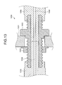
- FIG. 13 is a cross-sectional view illustrating a state in which SMA connectors are used as connectors to connect a conventional biological optical measurement apparatus and a measurement probe.
- a connector unit 1002 is fixed to a housing 1001 by a nut 1003.
- An SMA connector 1005 holding an optical fiber 1004 and an SMA connector 1006 holding an optical fiber 1004 are inserted into the connector unit 1002 from both ends of the connector unit 1002, respectively, and screwed and fixed to the connector unit 1002.
- an end surface of the SMA connector 1005 and an end surface of the SMA connector 1006 come into contact with each other, so that both optical fibers 1004 are optically connected to each other.
- Patent Literature 1 US Patent Application Publication No. 2010/0053632
- the conventional SMA connector described above has a problem that the inside of the connector unit comes into contact with the SMA connector and is worn away, and an end surface of the optical fiber of the measurement probe and the optical axes of the optical fibers of the biological optical measurement apparatus shift from each other, and thus connection efficiency between the optical fibers deteriorates.
- the diameter of the optical fiber is small, so that even when the abrasion of the connector unit is very small, the optical performance of the optical fiber is affected.
- the present invention has been made in view of the foregoing and an object of the invention is to provide a biological optical measurement apparatus, a measurement probe, and a biological optical measurement system that are capable of accurately determining the abrasion of the connector unit.
- a biological optical measurement apparatus is a biological optical measurement apparatus to which a measurement probe configured to be inserted into a subject is connected and which performs an optical measurement on body tissue.
- the biological optical measurement apparatus includes: a connector unit to which the measurement probe is detachably connected; a supply unit configured to supply air to the connector unit; a pipe that connects the connector unit and the supply unit; a pressure detection unit configured to detect a pressure value in the pipe; and an abrasion determination unit configured to determine abrasion of the connector unit based on the pressure value detected by the pressure detection unit under conditions that the measurement probe is connected to the connector unit.
- the connector unit includes: a cylindrical adapter member to which the measurement probe is configured to be inserted; a holding member which is configured to be inserted into the adapter member and holds an optical fiber that propagates light; and a fixing member which fixes the holding member to the adapter member.
- the adapter member includes: a cutout portion formed by circularly cutting out a surface of the adapter member facing the measurement probe, a groove portion which connects an outer circumferential side of the adapter member and the cutout portion, and a through hole which connects an inner circumferential side and the outer circumferential side and to which the supply unit is connected through the pipe.
- the connector unit has a cylindrical shape, holds an optical fiber that propagates light, and includes an insertion hole on a surface facing the measurement probe, the measurement probe being configured to be inserted into the insertion hole, the insertion hole includes a first groove portion and a second groove portion, which are circularly cut out along a longitudinal direction, the first groove portion includes an exhaust hole which penetrates in a radial direction and is configured to exhaust air in the connector unit, and the second groove portion includes a through hole which penetrates in a radial direction and to which the supply unit is connected through the pipe.
- the biological optical measurement apparatus further includes: an output unit configured to output information indicating that abrasion occurs in the connector unit; and an output controller configured to cause the output unit to output the information indicating that abrasion occurs in the connector unit when the abrasion determination unit determines that abrasion occurs in the connector unit.
- a measurement probe according to the invention is detachably connected to a connector unit of a biological optical measurement apparatus which performs an optical measurement on body tissue.
- the measurement probe includes: a holding member including a main body which has a cylindrical shape having the same diameter as an internal diameter of the connector unit and which is configured to be inserted into the connector unit and holds an optical fiber that propagates light, and including a ring-shaped flange portion which is provided so as to protrude from the main body in a radial direction and has a diameter smaller than an external diameter of the connector unit; and a fixing member which fixes the holding member to the connector unit.
- the main body includes a cutout portion which connects to a surface opposite to a surface facing the connector unit and which is partially cut out toward a center of the main body.
- the flange portion includes a groove portion which connects to the cutout portion and opens to an outer circumferential side, on a surface which faces the fixing member and which is perpendicular to a central axis of the holding member.
- a measurement probe according to the invention is detachably connected to a connector unit of a biological optical measurement apparatus which performs an optical measurement on body tissue.
- the measurement probe includes: a main body which has a cylindrical shape having the same diameter as an internal diameter of the connector unit, and includes a groove portion circularly cut out toward a center of the main body, and is configured to be inserted into the connector unit, and holds an optical fiber that propagates light; and a pressure member which has a ring shape and is attached to the groove portion, and is elastically deformed in a radial direction.
- a biological optical measurement system includes: a measurement probe configured to be inserted into a subject; and a biological optical measurement apparatus configured to perform an optical measurement on body tissue in the subject through the measurement probe.
- the biological optical measurement apparatus includes: a connector unit to which the measurement probe is detachably connected; a supply unit configured to supply air to the connector unit; a pipe that connects the connector unit and the supply unit; a pressure detection unit configured to detect a pressure value in the pipe; and an abrasion determination unit configured to determine abrasion of the connector unit based on the pressure value detected by the pressure detection unit under conditions that the measurement probe is connected to the connector unit.
- an abrasion determination unit determines abrasion of a connector unit based on a pressure value in a supply path detected by a pressure detection unit under conditions that a measurement probe is connected to the connector unit.
- the pressure detection unit is provided on a pipe between the connector unit and a supply unit that supplies air to the connector unit.
- FIG. 1 is a block diagram schematically illustrating a configuration of a biological optical measurement system according to a first embodiment of the present invention.
- a biological optical measurement system 1 illustrated in FIG. 1 includes a biological optical measurement apparatus 2 which performs optical measurements on an object to be measured such as body tissue that is a scatterer and detects the nature (characteristics) of an object to be measured and a measurement probe 3 which can be attached to and detached from the biological optical measurement apparatus 2 and is inserted into a subject.
- a biological optical measurement apparatus 2 which performs optical measurements on an object to be measured such as body tissue that is a scatterer and detects the nature (characteristics) of an object to be measured
- a measurement probe 3 which can be attached to and detached from the biological optical measurement apparatus 2 and is inserted into a subject.
- the biological optical measurement apparatus 2 includes a power supply 20, an illumination unit 21, a connector unit 22, a light receiving unit 23, a supply unit 24, a pressure detection unit 25, an input unit 26, an output unit 27, a recording unit 28, and a control unit 29.
- the power supply 20 supplies power to each unit of the biological optical measurement apparatus 2.
- the illumination unit 21 irradiates illumination light to an object to be measured through the connector unit 22.
- the illumination unit 21 is realized by an incoherent optical source such as a white LED (Light Emitting Diode), a xenon lamp, a tungsten lamp, and a halogen lamp and one or a plurality of lenses as needed. Examples of such lenses include a condenser lens and a collimating lens.
- the illumination unit 21 outputs incoherent light including at least one spectrum component to the measurement probe 3 as the illumination light irradiated to the object to be measured through the connector unit 22.
- the connector unit 22 detachably connects the measurement probe 3 to the biological optical measurement apparatus 2.
- the connector unit 22 is realized by using an SMA connector.
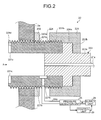
- FIG. 2 is a cross-sectional view of the connector unit 22 taken along a longitudinal direction of the connector unit 22.
- FIG. 3 is a front view of FIG. 2 as seen in an arrow A direction.
- the connector unit 22 includes an adapter member 221 provided to a housing 2a of the biological optical measurement apparatus 2, a first fixing member 222 that fixes the adapter member 221 to the housing 2a, a holding member 223 that can be inserted into the adapter member 221 and holds a plurality of optical fibers 21a, and a second fixing member 224 that fixes the holding member 223 to the adapter member 221.
- the adapter member 221 has a cylindrical shape and is formed by using stainless steel or the like.
- the adapter member 221 is provided so that a part of the adapter member 221 is exposed from the housing 2a of the biological optical measurement apparatus 2.
- An external thread portion 221a where thread ridges are provided at specified intervals on an outer circumferential surface of the adapter member 221 is formed on the adapter member 221.
- a through hole 221b that penetrates the adapter member 221 along a radial direction is formed in the adapter member 221.
- a cutout portion 221c (a spot facing) formed by circularly cutting out a surface of the adapter member 221 facing the measurement probe 3 is formed in the adapter member 221.
- a groove portion 221d that connects an outer circumferential side of the adapter member 221 and the cutout portion 221c is formed in a part of the outer circumference of the cutout portion 221c (see FIG. 3 ).
- the first fixing member 222 is configured by using a nut or the like.
- the first fixing member 222 has an internal thread portion 222a that can be screwed with the external thread portion 221a on the inner circumferential side.
- the first fixing member 222 fixes the adapter member 221 to the housing 2a by screwing the internal thread portion 222a to the external thread portion 221a of the adapter member 221.
- the holding member 223 is formed by using ceramic or the like.
- the holding member 223 includes a cylindrical main body 223a that holds the optical fibers 21a inside the main body 223a and a ring-shaped flange portion 223b provided so as to protrude in a radial direction of the main body 223a.
- the main body 223a is formed to have substantially the same diameter as the internal diameter of the adapter member 221 so that there is no gap when the main body 223a is inserted into the adapter member 221.
- the second fixing member 224 includes an insertion hole 224a which has a C-shaped cross-section and into which the holding member 223 can be inserted.
- the second fixing member 224 also has an internal thread portion 224b that can be screwed with the external thread portion 221a on a part of the inner circumference of the insertion hole 224a.
- the second fixing member 224 fixes the holding member 223 to the adapter member 221 by screwing the internal thread portion 224b to the external thread portion 221a of the adapter member 221.
- the connector unit 22 configured as described above optically connects the optical fibers 21a of the holding member 223 to the measurement probe 3. Thereby, the connector unit 22 propagates the illumination light emitted from the illumination unit 21 to the measurement probe 3 through the optical fibers 21a of the holding member 223 and propagates return light of the illumination light, which is emitted from the measurement probe 3 and reflected and/or scattered by body tissue, to the light receiving unit 23.
- a cross-section that passes through the central axis of the holding member 223 is used as an example.
- the light receiving unit 23 receives and measures return light of the illumination light that is emitted from the measurement probe 3 and reflected and/or scattered by an object to be measured.
- the light receiving unit 23 is realized by using a plurality of spectroscopic measurement devices, light receiving sensors, or the like. Specifically, in the light receiving unit 23, the spectroscopic measurement devices are provided according to the number of the light receiving fibers in the measurement probe described later.
- the light receiving unit 23 measures spectrum components and intensity distribution of scattered light emitted from the measurement probe 3 and outputs the measurement result to the control unit 29.
- the supply unit 24 supplies air into an interior space of the connector unit 22 under control of the control unit 29.
- the supply unit 24 is formed by using a pump or the like that sends air. Specifically, the supply unit 24 supplies air into the interior space of the connector unit 22 through a pipe 24a such as a tube and the through hole 221b in the adapter member 221 which function as a supply path in which the air is supplied (see FIG. 2 ).
- the pressure detection unit 25 is provided on the pipe 24a between the connector unit 22 and the supply unit 24.
- the pressure detection unit 25 detects a pressure value (atmospheric pressure) in the pipe 24a and outputs the measurement result to the control unit 29.
- the pressure detection unit 25 is realized by using a pressure sensor, an atmospheric pressure sensor, or the like.
- the input unit 26 receives an instruction signal that instructs start of the biological optical measurement apparatus 2 or an instruction signal that instructs other various operations and outputs the instruction signal to the control unit 29.
- the input unit 26 is realized by using push type switches, a touch panel, or the like.
- the output unit 27 outputs various information of the biological optical measurement apparatus 2. Specifically, the output unit 27 outputs information indicating that abrasion occurs in the connector unit 22 under control of the control unit 29.
- the output unit 27 is realized by using a display unit such as a liquid crystal, an organic EL (Electro Luminescence), or the like and a speaker or the like.
- the recording unit 28 records various programs for operating the biological optical measurement apparatus 2 and various data and parameters used for optical measurement processing.
- the recording unit 28 is realized by using a volatile memory, a non-volatile memory, and the like.
- the recording unit 28 temporarily records information being processed in the biological optical measurement apparatus 2. Further, the recording unit 28 records a measurement result of the subject measured by the biological optical measurement apparatus 2.
- the recording unit 28 may be formed by using a memory card or the like attached from the outside of the biological optical measurement apparatus 2.
- the control unit 29 controls processing operations of each unit of the biological optical measurement apparatus 2.
- the control unit 29 is configured by using a CPU (Central Processing Unit) or the like and integrally controls the biological optical measurement apparatus 2 by transmitting corresponding instruction information, data, and the like to each unit of the biological optical measurement apparatus 2.
- the control unit 29 includes a calculation unit 29a, an abrasion determination unit 29b, and an output controller 29c.
- the calculation unit 29a performs a plurality of arithmetic processes on the basis of a measurement result measured by the light receiving unit 23 and calculates a characteristic value related to the nature of the object to be measured. For example, a type of the characteristic value is set according to the instruction signal received by the input unit 26.
- the abrasion determination unit 29b determines abrasion of the connector unit 22 on the basis of the pressure value detected by the pressure detection unit 25 under the condition that the measurement probe 3 is connected to the connector unit 22. For example, the abrasion determination unit 29b determines whether or not the pressure value inputted from the pressure detection unit 25 is greater than or equal to a specified threshold value and when the pressure value is not greater than or equal to the threshold value, the abrasion determination unit 29b determines that abrasion occurs in the connector unit 22.
- the output controller 29c causes the output unit 27 to output information indicating that abrasion occurs in the connector unit 22.
- the measurement probe 3 is configured by using at least a plurality of optical fibers. Specifically, the measurement probe 3 is realized by using an illumination fiber that emits the illumination light to the object to be measured and a plurality of light receiving fibers into which return light of the illumination light reflected and/or scattered by the object to be measured enters at different angles.
- the measurement probe 3 includes a proximal end portion 31 detachably connected to the connector unit 22 of the biological optical measurement apparatus 2, a flexible portion 32 having flexibility, and a distal end portion that emits the illumination light supplied from the illumination unit 21 and receives the return light of the illumination light from the object to be measured.
- a distal end portion 33 is provided with a rod lens 34.
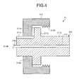
- FIG. 4 is a cross-sectional view of the proximal end portion 31 of the measurement probe 3 taken along a longitudinal direction of the proximal end portion 31.
- FIG. 5 is a front view of FIG. 4 as seen in an arrow B direction.
- the proximal end portion 31 includes a holding member 311 that can be inserted into the adapter member 221 and a fixing member 312 that fixes the holding member 311 to the adapter member 221.
- the holding member 311 includes a cylindrical main body 311a that holds optical fibers 21b inside the main body 311a and a ring-shaped flange portion 311b provided so as to protrude in a radial direction of the main body 311a.
- a cutout portion 311c is formed which connects to a surface opposite to a surface facing the connector unit 22 and which is partially cut out toward the center of the main body 311a.
- the diameter of the flange portion 311b is larger than the inside diameter of the adapter member 221 and smaller than the outside diameter of the adapter member 221.
- a groove portion 311d is formed, which connects to the cutout portion 311c and opens to the outer circumferential side, in a surface which faces the fixing member 312 and which is perpendicular to the central axis of the holding member 311.
- the fixing member 312 includes an insertion hole 312a which has a C-shaped cross-section and into which the holding member 311 can be inserted.
- the fixing member 312 also includes an external thread portion 312b, which can be screwed with the external thread portion 221a, on a part of an end portion of the inner circumferential surface.
- the fixing member 312 fixes the holding member 311 to the adapter member 221 by screwing the external thread portion 312b to the external thread portion 221a of the adapter member 221.
- the proximal end portion 31 of the measurement probe 3 configured like this is connected to the connector unit 22 of the biological optical measurement apparatus 2, so that the optical fibers 21a and the optical fibers 21b are optically connected.
- the measurement probe 3 is inserted into the subject through a treatment tool channel 11a provided on an endoscope apparatus 11 (an endoscope scope) of an endoscope system 10, the illumination fiber emits the illumination light to the object to be measured, and the light receiving fibers receives the return light of the illumination light, which is reflected and/or scattered by the object to be measured, at different angles and propagates the return light to the light receiving unit 23 of the biological optical measurement apparatus 2 to emit the return light.
- the calculation unit 29a calculates a characteristic value of the nature of the object to be measured on the basis of a measurement result of the light receiving unit 23.
- FIG. 8 is a flowchart illustrating an overview of the process performed by the biological optical measurement system 1.
- step S101: Yes when a start signal to start a measurement of body tissue is inputted from the input unit 26 (step S101: Yes), the control unit 29 drives the supply unit 24 to supply air into the adapter member 221 (step S102).
- step S103 determines whether or not a specified time has elapsed.
- step S103: Yes the biological optical measurement system 1 proceeds to step S104.
- step S103: No the biological optical measurement system 1 continues the process of step S103.
- step S104 the abrasion determination unit 29b determines whether or not a pressure value detected by the pressure detection unit 25 is greater than or equal to a specified threshold value. For example, as illustrated in FIG. 9 , when abrasion occurs on a surface of the inner circumferential side of the adapter member 221, if a gap generated by the abrasion is connected to the groove portion 311d and the air supplied by the supply unit 24 leaks to the outside, and thus the pressure value in the pipe 24a detected by the pressure detection unit 25 is not greater than or equal to the specified threshold value, the abrasion determination unit 29b determines that abrasion occurs in the connector unit 22. Thereby, a user can reliably know the abrasion generated by use in the connector unit 22.
- the biological optical measurement system 1 starts the measurement of the body tissue (step S105).
- step S106 the biological optical measurement system 1 ends the process.
- step S104 when the abrasion determination unit 29b determines that the pressure value detected by the pressure detection unit 25 is not greater than or equal to the specified threshold value (step S104: No), the output controller 29c causes the output unit 27 to output a warning indicating that the connector unit 22 is abraded (step S107). After step S107, the biological optical measurement system 1 ends the process.
- the abrasion determination unit 29b determines the abrasion of the connector unit 22 on the basis of the pressure value in the pipe 24a detected by the pressure detection unit 25 provided on the pipe 24a between the supply unit 24 that supplies air to the connector unit 22 and the connector unit 22, so that the abrasion of the connector unit 22 can be accurately detected.
- the output controller 29c causes the output unit 27 to output information indicating that abrasion occurs in the connector unit 22. As a result, a user can reliably know the abrasion of the connector unit 22.
- the supply unit 24 supplies air into the connector unit 22.
- the abrasion determination unit 29b determines whether or not the pressure value detected by the pressure detection unit 25 is smaller than or equal to a specified threshold value, so that the abrasion determination unit 29b may determine whether or not abrasion occurs in the connector unit 22.
- the connector unit of the biological optical measurement apparatus and the proximal end portion of the measurement probe are different from those in the first embodiment described above. Therefore, the connector unit of the biological optical measurement apparatus and the proximal end portion of the measurement probe will be described below.
- the same components as those in the first embodiment described above are given the same reference numerals.
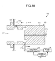
- FIG. 10 is a cross-sectional view of a connector unit 400 of a biological optical measurement apparatus 100 according to the second embodiment of the present invention taken along a central axis of the connector unit 400.
- the connector unit 400 illustrated in FIG. 10 includes a cylindrical main body 410 and a ring-shaped flange portion 420 provided so as to protrude in a radial direction of the main body 410.
- the main body 410 has a cylindrical shape and holds a plurality of optical fibers 21a.
- the main body 410 is provided with an insertion hole 411 into which a proximal end portion of a measurement probe 500 described later is inserted.
- a first groove portion 412 and a second groove portion 413 which are formed by circularly cutting the inside of the insertion hole 411 in the radial direction of the insertion hole 411, are formed in the main body 410.
- an exhaust hole 412a is formed which penetrates the main body 410 in the radial direction and exhausts air in the connector unit 400.
- a through hole 413a is formed which penetrates the main body 410 in the radial direction and is connected to the supply unit 24 through the pipe 24a.
- FIG. 11 is a cross-sectional view of the proximal end portion 600 of the measurement probe 500 according to the second embodiment of the present invention taken along a central axis of the proximal end portion 600.
- the proximal end portion 600 of the measurement probe 500 illustrated in FIG. 11 includes a cylindrical main body 610 and a ring-shaped pressure member 620.
- the main body 610 holds the optical fibers 21a.
- a groove portion 610a is formed by circularly cutting out the main body 610 toward the center.
- the pressure member 620 has a ring shape and is attached to the groove portion 610a of the main body 610.
- the pressure member 620 is configured by using a ring spring that can be elastically deformed in the radial direction.
- a height W2 of the pressure member 620 in a direction perpendicular to the diameter of the pressure member 620 is smaller than a groove width W1 of the groove portion 610a.
- the proximal end portion 600 of the measurement probe 500 when the proximal end portion 600 of the measurement probe 500 is inserted into the connector unit 400, the proximal end portion 600 is inserted in a state in which the diameter of the pressure member 620 is the same as that of the insertion hole 411 of the connector unit 400 and the pressure member 620 is compressed toward the center. Thereafter, as illustrated in FIG. 12 , when the pressure member 620 reaches the first groove portion 412, the pressure member 620 expands in the radial direction. At this time, the pressure member 620 receives a rightward force in FIG. 12 from the connector unit 400 (an effect of an R surface).
- the proximal end portion 600 is fixed to the connector unit 400 so that the proximal end portion 600 is not pulled out from the connector unit 400.
- the proximal end portion 600 is pressed to the connector unit 400, so that connection efficiency is ensured.
- a user can connect the measurement probe 500 to the biological optical measurement apparatus 100 by a single operation and optically connect the optical fibers 21a held by the connector unit 400 and the optical fibers 21b of the measurement probe 500.
- the control unit 29 causes the supply unit 24 to supply air under the condition that the measurement probe 500 is connected to the connector unit 400.
- the abrasion determination unit 29b determines abrasion of the connector unit 400 on the basis of the pressure value detected by the pressure detection unit 25 after a specified time has elapsed. Thereafter, when the abrasion determination unit 29b determines that abrasion occurs in the connector unit 400, the output controller 29c causes the output unit 27 to output information indicating that abrasion occurs in the connector unit 400. Thereby, the user can accurately know the abrasion generated in the connector unit 400.
- the measurement probe 500 it is possible to connect the measurement probe 500 to the connector unit 400 by a single operation, and it is also possible to determine abrasion of the connector unit 400.
- the configurations of the connector unit 400 and the measurement probe 500 can be simpler than those in the first embodiment described above.
Landscapes
- Health & Medical Sciences (AREA)
- Life Sciences & Earth Sciences (AREA)
- Surgery (AREA)
- General Health & Medical Sciences (AREA)
- Medical Informatics (AREA)
- Veterinary Medicine (AREA)
- Pathology (AREA)
- Public Health (AREA)
- Biophysics (AREA)
- Engineering & Computer Science (AREA)
- Biomedical Technology (AREA)
- Heart & Thoracic Surgery (AREA)
- Physics & Mathematics (AREA)
- Molecular Biology (AREA)
- Animal Behavior & Ethology (AREA)
- Nuclear Medicine, Radiotherapy & Molecular Imaging (AREA)
- Radiology & Medical Imaging (AREA)
- Optics & Photonics (AREA)
- Investigating Or Analysing Materials By Optical Means (AREA)
- Endoscopes (AREA)
- Measurement Of The Respiration, Hearing Ability, Form, And Blood Characteristics Of Living Organisms (AREA)
Abstract
Description
- The present invention relates to a biological optical measurement apparatus which measures optical characteristics of body tissue, a measurement probe connected to the biological optical measurement apparatus, and a biological optical measurement system.
- In recent years, a biological optical measurement apparatus is known which irradiates illumination light to body tissue and estimates the nature of the body tissue on the basis of measurement values of detected light reflected or scattered from the body tissue. The biological optical measurement apparatus is used in combination with an endoscope for observing an internal organ such as a digestive organ. As such a biological optical measurement apparatus, a biological optical measurement apparatus is proposed which uses LEBS (Low-Coherence Enhanced Backscattering Spectroscopy) that detects the nature of body tissue by irradiating low-coherence white light whose spatial coherence length is short from the tip of an illumination fiber of a measurement probe to the body tissue and measuring intensity distribution of scattering light of a plurality of angles by using a plurality of light receiving fibers (see Patent Literature 1).
- The biological optical measurement apparatus and the measurement probe described above are optically connected to each other by using an SMA (Sub-Miniature Type A) connector.
FIG. 13 is a cross-sectional view illustrating a state in which SMA connectors are used as connectors to connect a conventional biological optical measurement apparatus and a measurement probe. In a biologicaloptical measurement apparatus 1000 illustrated inFIG. 13 , aconnector unit 1002 is fixed to ahousing 1001 by anut 1003. AnSMA connector 1005 holding anoptical fiber 1004 and anSMA connector 1006 holding anoptical fiber 1004 are inserted into theconnector unit 1002 from both ends of theconnector unit 1002, respectively, and screwed and fixed to theconnector unit 1002. Thereby, an end surface of theSMA connector 1005 and an end surface of theSMA connector 1006 come into contact with each other, so that bothoptical fibers 1004 are optically connected to each other. - Patent Literature 1:
US Patent Application Publication No. 2010/0053632 - However, the conventional SMA connector described above has a problem that the inside of the connector unit comes into contact with the SMA connector and is worn away, and an end surface of the optical fiber of the measurement probe and the optical axes of the optical fibers of the biological optical measurement apparatus shift from each other, and thus connection efficiency between the optical fibers deteriorates. In the biological optical measurement apparatus, the diameter of the optical fiber is small, so that even when the abrasion of the connector unit is very small, the optical performance of the optical fiber is affected.
- On the other hand, in the biological optical measurement apparatus, even when the abrasion of the connector unit increases, it does not affect the feeling of attaching and removing the measurement probe, so that a user cannot recognize the abrasion of the connector unit. Thus, a technique for accurately determining the abrasion of the connector unit is desired.
- The present invention has been made in view of the foregoing and an object of the invention is to provide a biological optical measurement apparatus, a measurement probe, and a biological optical measurement system that are capable of accurately determining the abrasion of the connector unit.
- To solve the problem described above and achieve the object, a biological optical measurement apparatus according to the invention is a biological optical measurement apparatus to which a measurement probe configured to be inserted into a subject is connected and which performs an optical measurement on body tissue. The biological optical measurement apparatus includes: a connector unit to which the measurement probe is detachably connected; a supply unit configured to supply air to the connector unit; a pipe that connects the connector unit and the supply unit; a pressure detection unit configured to detect a pressure value in the pipe; and an abrasion determination unit configured to determine abrasion of the connector unit based on the pressure value detected by the pressure detection unit under conditions that the measurement probe is connected to the connector unit.
- In the above invention, according to the biological optical measurement apparatus of the invention, the connector unit includes: a cylindrical adapter member to which the measurement probe is configured to be inserted; a holding member which is configured to be inserted into the adapter member and holds an optical fiber that propagates light; and a fixing member which fixes the holding member to the adapter member. The adapter member includes: a cutout portion formed by circularly cutting out a surface of the adapter member facing the measurement probe, a groove portion which connects an outer circumferential side of the adapter member and the cutout portion, and a through hole which connects an inner circumferential side and the outer circumferential side and to which the supply unit is connected through the pipe.
- In the above invention, according to the biological optical measurement apparatus of the invention, the connector unit has a cylindrical shape, holds an optical fiber that propagates light, and includes an insertion hole on a surface facing the measurement probe, the measurement probe being configured to be inserted into the insertion hole, the insertion hole includes a first groove portion and a second groove portion, which are circularly cut out along a longitudinal direction, the first groove portion includes an exhaust hole which penetrates in a radial direction and is configured to exhaust air in the connector unit, and the second groove portion includes a through hole which penetrates in a radial direction and to which the supply unit is connected through the pipe.
- In the above invention, the biological optical measurement apparatus according to the invention further includes: an output unit configured to output information indicating that abrasion occurs in the connector unit; and an output controller configured to cause the output unit to output the information indicating that abrasion occurs in the connector unit when the abrasion determination unit determines that abrasion occurs in the connector unit.
- A measurement probe according to the invention is detachably connected to a connector unit of a biological optical measurement apparatus which performs an optical measurement on body tissue. The measurement probe includes: a holding member including a main body which has a cylindrical shape having the same diameter as an internal diameter of the connector unit and which is configured to be inserted into the connector unit and holds an optical fiber that propagates light, and including a ring-shaped flange portion which is provided so as to protrude from the main body in a radial direction and has a diameter smaller than an external diameter of the connector unit; and a fixing member which fixes the holding member to the connector unit. The main body includes a cutout portion which connects to a surface opposite to a surface facing the connector unit and which is partially cut out toward a center of the main body. The flange portion includes a groove portion which connects to the cutout portion and opens to an outer circumferential side, on a surface which faces the fixing member and which is perpendicular to a central axis of the holding member.
- A measurement probe according to the invention is detachably connected to a connector unit of a biological optical measurement apparatus which performs an optical measurement on body tissue. The measurement probe includes: a main body which has a cylindrical shape having the same diameter as an internal diameter of the connector unit, and includes a groove portion circularly cut out toward a center of the main body, and is configured to be inserted into the connector unit, and holds an optical fiber that propagates light; and a pressure member which has a ring shape and is attached to the groove portion, and is elastically deformed in a radial direction.
- A biological optical measurement system according to the invention includes: a measurement probe configured to be inserted into a subject; and a biological optical measurement apparatus configured to perform an optical measurement on body tissue in the subject through the measurement probe. The biological optical measurement apparatus includes: a connector unit to which the measurement probe is detachably connected; a supply unit configured to supply air to the connector unit; a pipe that connects the connector unit and the supply unit; a pressure detection unit configured to detect a pressure value in the pipe; and an abrasion determination unit configured to determine abrasion of the connector unit based on the pressure value detected by the pressure detection unit under conditions that the measurement probe is connected to the connector unit.
- According to the invention, an abrasion determination unit determines abrasion of a connector unit based on a pressure value in a supply path detected by a pressure detection unit under conditions that a measurement probe is connected to the connector unit. The pressure detection unit is provided on a pipe between the connector unit and a supply unit that supplies air to the connector unit. With this configuration, it is possible to accurately determine the abrasion of the connector unit.
-
-
FIG. 1 is a block diagram schematically illustrating a configuration of a biological optical measurement system according to a first embodiment of the present invention. -
FIG. 2 is a cross-sectional view of a connector unit of a biological optical measurement apparatus of the biological optical measurement system according to the first embodiment of the present invention taken along a central axis of the connector unit. -
FIG. 3 is a front view ofFIG. 2 as seen in an arrow A direction. -
FIG. 4 is a cross-sectional view of a proximal end portion of a measurement probe of the biological optical measurement system according to the first embodiment of the present invention taken along a central axis of the proximal end portion. -
FIG. 5 is a front view ofFIG. 4 as seen in an arrow B direction. -
FIG. 6 is a cross-sectional view illustrating a state in which the measurement probe is connected to the biological optical measurement apparatus of the biological optical measurement system according to the first embodiment of the present invention. -
FIG. 7 is a view illustrating a state in which the biological optical measurement system according to the first embodiment is used in an endoscope system. -
FIG. 8 is a flowchart illustrating an overview of a process performed by the biological optical measurement system of the present invention. -
FIG. 9 is a cross-sectional view illustrating a state in which abrasion occurs in the connector unit of the biological optical measurement apparatus according to the first embodiment of the present invention. -
FIG. 10 is a cross-sectional view of a connector unit of a biological optical measurement apparatus of a biological optical measurement system according to a second embodiment of the present invention taken along a central axis of the connector unit. -
FIG. 11 is a cross-sectional view of a proximal end portion of a measurement probe of the biological optical measurement system according to the second embodiment of the present invention taken along a central axis of the proximal end portion. -
FIG. 12 is a cross-sectional view illustrating a state in which the measurement probe is connected to the biological optical measurement apparatus of the biological optical measurement system according to the second embodiment of the present invention. -
FIG. 13 is a cross-sectional view illustrating a state in which SAM connectors are used as connectors to connect a conventional biological optical measurement apparatus and a measurement probe. - Hereinafter, modes for carrying out the present invention (hereinafter referred to as "embodiments") will be described with reference to the drawings. In the description of the drawings, the same components are given the same reference numerals. Note that the drawings are schematic and relationships between the thickness and width of each component and ratios between each component are different from the actual values. Further, there may be differences in dimensions and ratios between the drawings. The present invention is not limited by the embodiments.
-
FIG. 1 is a block diagram schematically illustrating a configuration of a biological optical measurement system according to a first embodiment of the present invention. - A biological optical measurement system 1 illustrated in
FIG. 1 includes a biologicaloptical measurement apparatus 2 which performs optical measurements on an object to be measured such as body tissue that is a scatterer and detects the nature (characteristics) of an object to be measured and ameasurement probe 3 which can be attached to and detached from the biologicaloptical measurement apparatus 2 and is inserted into a subject. - First, the biological
optical measurement apparatus 2 will be described. The biologicaloptical measurement apparatus 2 includes apower supply 20, anillumination unit 21, aconnector unit 22, alight receiving unit 23, asupply unit 24, apressure detection unit 25, aninput unit 26, anoutput unit 27, arecording unit 28, and acontrol unit 29. Thepower supply 20 supplies power to each unit of the biologicaloptical measurement apparatus 2. - The
illumination unit 21 irradiates illumination light to an object to be measured through theconnector unit 22. Theillumination unit 21 is realized by an incoherent optical source such as a white LED (Light Emitting Diode), a xenon lamp, a tungsten lamp, and a halogen lamp and one or a plurality of lenses as needed. Examples of such lenses include a condenser lens and a collimating lens. Theillumination unit 21 outputs incoherent light including at least one spectrum component to themeasurement probe 3 as the illumination light irradiated to the object to be measured through theconnector unit 22. - The
connector unit 22 detachably connects themeasurement probe 3 to the biologicaloptical measurement apparatus 2. Theconnector unit 22 is realized by using an SMA connector. - Here, a detailed configuration of the
connector unit 22 will be described.FIG. 2 is a cross-sectional view of theconnector unit 22 taken along a longitudinal direction of theconnector unit 22.FIG. 3 is a front view ofFIG. 2 as seen in an arrow A direction. - As illustrated in
FIGS. 2 and3 , theconnector unit 22 includes anadapter member 221 provided to ahousing 2a of the biologicaloptical measurement apparatus 2, a first fixingmember 222 that fixes theadapter member 221 to thehousing 2a, a holdingmember 223 that can be inserted into theadapter member 221 and holds a plurality ofoptical fibers 21a, and asecond fixing member 224 that fixes the holdingmember 223 to theadapter member 221. - The
adapter member 221 has a cylindrical shape and is formed by using stainless steel or the like. Theadapter member 221 is provided so that a part of theadapter member 221 is exposed from thehousing 2a of the biologicaloptical measurement apparatus 2. Anexternal thread portion 221a where thread ridges are provided at specified intervals on an outer circumferential surface of theadapter member 221 is formed on theadapter member 221. A throughhole 221b that penetrates theadapter member 221 along a radial direction is formed in theadapter member 221. Further, acutout portion 221c (a spot facing) formed by circularly cutting out a surface of theadapter member 221 facing themeasurement probe 3 is formed in theadapter member 221. Agroove portion 221d that connects an outer circumferential side of theadapter member 221 and thecutout portion 221c is formed in a part of the outer circumference of thecutout portion 221c (seeFIG. 3 ). - The
first fixing member 222 is configured by using a nut or the like. Thefirst fixing member 222 has aninternal thread portion 222a that can be screwed with theexternal thread portion 221a on the inner circumferential side. Thefirst fixing member 222 fixes theadapter member 221 to thehousing 2a by screwing theinternal thread portion 222a to theexternal thread portion 221a of theadapter member 221. - The holding
member 223 is formed by using ceramic or the like. The holdingmember 223 includes a cylindricalmain body 223a that holds theoptical fibers 21a inside themain body 223a and a ring-shapedflange portion 223b provided so as to protrude in a radial direction of themain body 223a. Themain body 223a is formed to have substantially the same diameter as the internal diameter of theadapter member 221 so that there is no gap when themain body 223a is inserted into theadapter member 221. - The
second fixing member 224 includes aninsertion hole 224a which has a C-shaped cross-section and into which the holdingmember 223 can be inserted. Thesecond fixing member 224 also has aninternal thread portion 224b that can be screwed with theexternal thread portion 221a on a part of the inner circumference of theinsertion hole 224a. Thesecond fixing member 224 fixes the holdingmember 223 to theadapter member 221 by screwing theinternal thread portion 224b to theexternal thread portion 221a of theadapter member 221. - The
connector unit 22 configured as described above optically connects theoptical fibers 21a of the holdingmember 223 to themeasurement probe 3. Thereby, theconnector unit 22 propagates the illumination light emitted from theillumination unit 21 to themeasurement probe 3 through theoptical fibers 21a of the holdingmember 223 and propagates return light of the illumination light, which is emitted from themeasurement probe 3 and reflected and/or scattered by body tissue, to thelight receiving unit 23. InFIG. 2 , a cross-section that passes through the central axis of the holdingmember 223 is used as an example. - Return to
FIG. 1 , the description of the configuration of the biologicaloptical measurement apparatus 2 will be continued. - The
light receiving unit 23 receives and measures return light of the illumination light that is emitted from themeasurement probe 3 and reflected and/or scattered by an object to be measured. Thelight receiving unit 23 is realized by using a plurality of spectroscopic measurement devices, light receiving sensors, or the like. Specifically, in thelight receiving unit 23, the spectroscopic measurement devices are provided according to the number of the light receiving fibers in the measurement probe described later. Thelight receiving unit 23 measures spectrum components and intensity distribution of scattered light emitted from themeasurement probe 3 and outputs the measurement result to thecontrol unit 29. - The
supply unit 24 supplies air into an interior space of theconnector unit 22 under control of thecontrol unit 29. Thesupply unit 24 is formed by using a pump or the like that sends air. Specifically, thesupply unit 24 supplies air into the interior space of theconnector unit 22 through apipe 24a such as a tube and the throughhole 221b in theadapter member 221 which function as a supply path in which the air is supplied (seeFIG. 2 ). - The
pressure detection unit 25 is provided on thepipe 24a between theconnector unit 22 and thesupply unit 24. Thepressure detection unit 25 detects a pressure value (atmospheric pressure) in thepipe 24a and outputs the measurement result to thecontrol unit 29. Thepressure detection unit 25 is realized by using a pressure sensor, an atmospheric pressure sensor, or the like. - The
input unit 26 receives an instruction signal that instructs start of the biologicaloptical measurement apparatus 2 or an instruction signal that instructs other various operations and outputs the instruction signal to thecontrol unit 29. Theinput unit 26 is realized by using push type switches, a touch panel, or the like. - The
output unit 27 outputs various information of the biologicaloptical measurement apparatus 2. Specifically, theoutput unit 27 outputs information indicating that abrasion occurs in theconnector unit 22 under control of thecontrol unit 29. Theoutput unit 27 is realized by using a display unit such as a liquid crystal, an organic EL (Electro Luminescence), or the like and a speaker or the like. - The
recording unit 28 records various programs for operating the biologicaloptical measurement apparatus 2 and various data and parameters used for optical measurement processing. Therecording unit 28 is realized by using a volatile memory, a non-volatile memory, and the like. Therecording unit 28 temporarily records information being processed in the biologicaloptical measurement apparatus 2. Further, therecording unit 28 records a measurement result of the subject measured by the biologicaloptical measurement apparatus 2. Therecording unit 28 may be formed by using a memory card or the like attached from the outside of the biologicaloptical measurement apparatus 2. - The
control unit 29 controls processing operations of each unit of the biologicaloptical measurement apparatus 2. Thecontrol unit 29 is configured by using a CPU (Central Processing Unit) or the like and integrally controls the biologicaloptical measurement apparatus 2 by transmitting corresponding instruction information, data, and the like to each unit of the biologicaloptical measurement apparatus 2. Thecontrol unit 29 includes acalculation unit 29a, anabrasion determination unit 29b, and anoutput controller 29c. - The
calculation unit 29a performs a plurality of arithmetic processes on the basis of a measurement result measured by thelight receiving unit 23 and calculates a characteristic value related to the nature of the object to be measured. For example, a type of the characteristic value is set according to the instruction signal received by theinput unit 26. - The
abrasion determination unit 29b determines abrasion of theconnector unit 22 on the basis of the pressure value detected by thepressure detection unit 25 under the condition that themeasurement probe 3 is connected to theconnector unit 22. For example, theabrasion determination unit 29b determines whether or not the pressure value inputted from thepressure detection unit 25 is greater than or equal to a specified threshold value and when the pressure value is not greater than or equal to the threshold value, theabrasion determination unit 29b determines that abrasion occurs in theconnector unit 22. - When the
abrasion determination unit 29b determines that abrasion occurs in theconnector unit 22, theoutput controller 29c causes theoutput unit 27 to output information indicating that abrasion occurs in theconnector unit 22. - Next, the
measurement probe 3 will be described. Themeasurement probe 3 is configured by using at least a plurality of optical fibers. Specifically, themeasurement probe 3 is realized by using an illumination fiber that emits the illumination light to the object to be measured and a plurality of light receiving fibers into which return light of the illumination light reflected and/or scattered by the object to be measured enters at different angles. Themeasurement probe 3 includes aproximal end portion 31 detachably connected to theconnector unit 22 of the biologicaloptical measurement apparatus 2, aflexible portion 32 having flexibility, and a distal end portion that emits the illumination light supplied from theillumination unit 21 and receives the return light of the illumination light from the object to be measured. Adistal end portion 33 is provided with arod lens 34. - Here, a detailed configuration of the
proximal end portion 31 of themeasurement probe 3 will be described.FIG. 4 is a cross-sectional view of theproximal end portion 31 of themeasurement probe 3 taken along a longitudinal direction of theproximal end portion 31.FIG. 5 is a front view ofFIG. 4 as seen in an arrow B direction. - As illustrated in
FIGS. 4 and5 , theproximal end portion 31 includes a holdingmember 311 that can be inserted into theadapter member 221 and a fixingmember 312 that fixes the holdingmember 311 to theadapter member 221. - The holding
member 311 includes a cylindricalmain body 311a that holdsoptical fibers 21b inside themain body 311a and a ring-shapedflange portion 311b provided so as to protrude in a radial direction of themain body 311a. In themain body 311a, acutout portion 311c is formed which connects to a surface opposite to a surface facing theconnector unit 22 and which is partially cut out toward the center of themain body 311a. The diameter of theflange portion 311b is larger than the inside diameter of theadapter member 221 and smaller than the outside diameter of theadapter member 221. Further, in theflange portion 311b, agroove portion 311d is formed, which connects to thecutout portion 311c and opens to the outer circumferential side, in a surface which faces the fixingmember 312 and which is perpendicular to the central axis of the holdingmember 311. - The fixing
member 312 includes aninsertion hole 312a which has a C-shaped cross-section and into which the holdingmember 311 can be inserted. The fixingmember 312 also includes anexternal thread portion 312b, which can be screwed with theexternal thread portion 221a, on a part of an end portion of the inner circumferential surface. The fixingmember 312 fixes the holdingmember 311 to theadapter member 221 by screwing theexternal thread portion 312b to theexternal thread portion 221a of theadapter member 221. - As illustrated in
FIG. 6 , theproximal end portion 31 of themeasurement probe 3 configured like this is connected to theconnector unit 22 of the biologicaloptical measurement apparatus 2, so that theoptical fibers 21a and theoptical fibers 21b are optically connected. - As illustrated in
FIG. 7 , in the biological optical measurement system 1 configured as described above, themeasurement probe 3 is inserted into the subject through atreatment tool channel 11a provided on an endoscope apparatus 11 (an endoscope scope) of anendoscope system 10, the illumination fiber emits the illumination light to the object to be measured, and the light receiving fibers receives the return light of the illumination light, which is reflected and/or scattered by the object to be measured, at different angles and propagates the return light to thelight receiving unit 23 of the biologicaloptical measurement apparatus 2 to emit the return light. Thereafter, thecalculation unit 29a calculates a characteristic value of the nature of the object to be measured on the basis of a measurement result of thelight receiving unit 23. - Next, a process performed by the biological optical measurement system 1 will be described.
FIG. 8 is a flowchart illustrating an overview of the process performed by the biological optical measurement system 1. - As illustrated in
FIG. 8 , under the condition that themeasurement probe 3 is connected to the biologicaloptical measurement apparatus 2, when a start signal to start a measurement of body tissue is inputted from the input unit 26 (step S101: Yes), thecontrol unit 29 drives thesupply unit 24 to supply air into the adapter member 221 (step S102). - Subsequently, the
control unit 29 determines whether or not a specified time has elapsed (step S103). When thecontrol unit 29 determines that the specified time has elapsed (step S103: Yes), the biological optical measurement system 1 proceeds to step S104. On the contrary, when thecontrol unit 29 determines that the specified time has not elapsed (step S103: No), the biological optical measurement system 1 continues the process of step S103. - In step S104, the
abrasion determination unit 29b determines whether or not a pressure value detected by thepressure detection unit 25 is greater than or equal to a specified threshold value. For example, as illustrated inFIG. 9 , when abrasion occurs on a surface of the inner circumferential side of theadapter member 221, if a gap generated by the abrasion is connected to thegroove portion 311d and the air supplied by thesupply unit 24 leaks to the outside, and thus the pressure value in thepipe 24a detected by thepressure detection unit 25 is not greater than or equal to the specified threshold value, theabrasion determination unit 29b determines that abrasion occurs in theconnector unit 22. Thereby, a user can reliably know the abrasion generated by use in theconnector unit 22. When theabrasion determination unit 29b determines that the pressure value detected by thepressure detection unit 25 is greater than or equal to the specified threshold value (step S104: Yes), the biological optical measurement system 1 starts the measurement of the body tissue (step S105). - Subsequently, the
output controller 29c causes theoutput unit 27 to output a measurement result (step S106). After step S106, the biological optical measurement system 1 ends the process. - In step S104, when the
abrasion determination unit 29b determines that the pressure value detected by thepressure detection unit 25 is not greater than or equal to the specified threshold value (step S104: No), theoutput controller 29c causes theoutput unit 27 to output a warning indicating that theconnector unit 22 is abraded (step S107). After step S107, the biological optical measurement system 1 ends the process. - According to the first embodiment of the present invention described above, under the condition that the
measurement probe 3 is connected to theconnector unit 22, theabrasion determination unit 29b determines the abrasion of theconnector unit 22 on the basis of the pressure value in thepipe 24a detected by thepressure detection unit 25 provided on thepipe 24a between thesupply unit 24 that supplies air to theconnector unit 22 and theconnector unit 22, so that the abrasion of theconnector unit 22 can be accurately detected. - Further, according to the first embodiment of the present invention, when the
abrasion determination unit 29b determines that abrasion occurs in theconnector unit 22, theoutput controller 29c causes theoutput unit 27 to output information indicating that abrasion occurs in theconnector unit 22. As a result, a user can reliably know the abrasion of theconnector unit 22. - In the first embodiment of the present invention, the
supply unit 24 supplies air into theconnector unit 22. However, for example, it is possible to absorb air in theconnector unit 22 and generate a negative pressure in theconnector unit 22. In this case, theabrasion determination unit 29b determines whether or not the pressure value detected by thepressure detection unit 25 is smaller than or equal to a specified threshold value, so that theabrasion determination unit 29b may determine whether or not abrasion occurs in theconnector unit 22. - Next, a second embodiment of the present invention will be described. In the biological optical measurement system according to the second embodiment, the connector unit of the biological optical measurement apparatus and the proximal end portion of the measurement probe are different from those in the first embodiment described above. Therefore, the connector unit of the biological optical measurement apparatus and the proximal end portion of the measurement probe will be described below. The same components as those in the first embodiment described above are given the same reference numerals.
-
FIG. 10 is a cross-sectional view of aconnector unit 400 of a biologicaloptical measurement apparatus 100 according to the second embodiment of the present invention taken along a central axis of theconnector unit 400. - The
connector unit 400 illustrated inFIG. 10 includes a cylindricalmain body 410 and a ring-shapedflange portion 420 provided so as to protrude in a radial direction of themain body 410. - The
main body 410 has a cylindrical shape and holds a plurality ofoptical fibers 21a. Themain body 410 is provided with aninsertion hole 411 into which a proximal end portion of ameasurement probe 500 described later is inserted. Afirst groove portion 412 and asecond groove portion 413, which are formed by circularly cutting the inside of theinsertion hole 411 in the radial direction of theinsertion hole 411, are formed in themain body 410. In thefirst groove portion 412, anexhaust hole 412a is formed which penetrates themain body 410 in the radial direction and exhausts air in theconnector unit 400. In thesecond groove portion 413, a throughhole 413a is formed which penetrates themain body 410 in the radial direction and is connected to thesupply unit 24 through thepipe 24a. - Next, a
proximal end portion 600 of themeasurement probe 500 will be described.FIG. 11 is a cross-sectional view of theproximal end portion 600 of themeasurement probe 500 according to the second embodiment of the present invention taken along a central axis of theproximal end portion 600. - The
proximal end portion 600 of themeasurement probe 500 illustrated inFIG. 11 includes a cylindricalmain body 610 and a ring-shapedpressure member 620. - The
main body 610 holds theoptical fibers 21a. In themain body 610, agroove portion 610a is formed by circularly cutting out themain body 610 toward the center. - The
pressure member 620 has a ring shape and is attached to thegroove portion 610a of themain body 610. Thepressure member 620 is configured by using a ring spring that can be elastically deformed in the radial direction. A height W2 of thepressure member 620 in a direction perpendicular to the diameter of thepressure member 620 is smaller than a groove width W1 of thegroove portion 610a. - In the biological
optical measurement apparatus 100 configured like this, when theproximal end portion 600 of themeasurement probe 500 is inserted into theconnector unit 400, theproximal end portion 600 is inserted in a state in which the diameter of thepressure member 620 is the same as that of theinsertion hole 411 of theconnector unit 400 and thepressure member 620 is compressed toward the center. Thereafter, as illustrated inFIG. 12 , when thepressure member 620 reaches thefirst groove portion 412, thepressure member 620 expands in the radial direction. At this time, thepressure member 620 receives a rightward force inFIG. 12 from the connector unit 400 (an effect of an R surface). Thereby, theproximal end portion 600 is fixed to theconnector unit 400 so that theproximal end portion 600 is not pulled out from theconnector unit 400. At the same time, theproximal end portion 600 is pressed to theconnector unit 400, so that connection efficiency is ensured. As a result, a user can connect themeasurement probe 500 to the biologicaloptical measurement apparatus 100 by a single operation and optically connect theoptical fibers 21a held by theconnector unit 400 and theoptical fibers 21b of themeasurement probe 500. - The
control unit 29 causes thesupply unit 24 to supply air under the condition that themeasurement probe 500 is connected to theconnector unit 400. In this case, theabrasion determination unit 29b determines abrasion of theconnector unit 400 on the basis of the pressure value detected by thepressure detection unit 25 after a specified time has elapsed. Thereafter, when theabrasion determination unit 29b determines that abrasion occurs in theconnector unit 400, theoutput controller 29c causes theoutput unit 27 to output information indicating that abrasion occurs in theconnector unit 400. Thereby, the user can accurately know the abrasion generated in theconnector unit 400. - According to the second embodiment of the present invention described above, it is possible to connect the
measurement probe 500 to theconnector unit 400 by a single operation, and it is also possible to determine abrasion of theconnector unit 400. - Further, according to the second embodiment of the present invention, the configurations of the
connector unit 400 and themeasurement probe 500 can be simpler than those in the first embodiment described above. -
- 1 biological optical measurement system
- 2, 100, 1000 biological optical measurement apparatus
- 2a, 1001 housing
- 3, 500 measurement probe
- 10 endoscope system
- 11 endoscope apparatus
- 11a treatment tool channel
- 20 power supply
- 21a, 21b, 1004 optical fiber
- 21 illumination unit
- 22, 1002 connector unit
- 23 light receiving unit
- 24 supply unit
- 24a pipe
- 25 pressure detection unit
- 26 input unit
- 27 output unit
- 28 recording unit
- 29 control unit
- 29a calculation unit
- 29b abrasion determination unit
- 29c output controller
- 31, 600 proximal end portion
- 32 flexible portion
- 33 distal end portion
- 34 rod lens
- 221 adapter member
- 221a external thread portion
- 221b, 413a through hole
- 221c, 311c cutout portion
- 221d, 311d, 610a groove portion
- 222, 224, 312 fixing member
- 222a, 224b, 312b internal thread portion
- 223, 311 holding member
- 223a, 311a, 410, 610 main body
- 223b, 311b, 420 flange portion
- 224a, 312a, 411 insertion hole
- 400 connector unit
- 412 first groove portion
- 412a exhaust hole
- 413 second groove portion
- 620 pressure member
- 1003 nut
- 1005, 1006 SMA connector
Claims (7)
- A biological optical measurement apparatus to which a measurement probe configured to be inserted into a subject is connected and which performs an optical measurement on body tissue, the biological optical measurement apparatus comprising:a connector unit to which the measurement probe is detachably connected;a supply unit configured to supply air to the connector unit;a pipe that connects the connector unit and the supply unit;a pressure detection unit configured to detect a pressure value in the pipe; andan abrasion determination unit configured to determine abrasion of the connector unit based on the pressure value detected by the pressure detection unit under conditions that the measurement probe is connected to the connector unit.
- The biological optical measurement apparatus according to claim 1,
wherein the connector unit includes:a cylindrical adapter member to which the measurement probe is configured to be inserted;a holding member which is configured to be inserted into the adapter member and holds an optical fiber that propagates light; anda fixing member which fixes the holding member to the adapter member, andwherein the adapter member includes:a cutout portion formed by circularly cutting out a surface of the adapter member facing the measurement probe,
a groove portion which connects an outer circumferential side of the adapter member and the cutout portion, and
a through hole which connects an inner circumferential side and the outer circumferential side and to which the supply unit is connected through the pipe. - The biological optical measurement apparatus according to claim 1, wherein
the connector unit has a cylindrical shape, holds an optical fiber that propagates light, and includes an insertion hole on a surface facing the measurement probe, the measurement probe being configured to be inserted into the insertion hole,
the insertion hole includes a first groove portion and a second groove portion, which are circularly cut out along a longitudinal direction,
the first groove portion includes an exhaust hole which penetrates in a radial direction and is configured to exhaust air in the connector unit, and
the second groove portion includes a through hole which penetrates in a radial direction and to which the supply unit is connected through the pipe. - The biological optical measurement apparatus according to claim 1, further comprising:an output unit configured to output information indicating that abrasion occurs in the connector unit; andan output controller configured to cause the output unit to output the information indicating that abrasion occurs in the connector unit when the abrasion determination unit determines that abrasion occurs in the connector unit.
- A measurement probe detachably connected to a connector unit of a biological optical measurement apparatus which performs an optical measurement on body tissue, the measurement probe comprising:a holding member including a main body which has a cylindrical shape having the same diameter as an internal diameter of the connector unit and which is configured to be inserted into the connector unit and holds an optical fiber that propagates light, and including a ring-shaped flange portion which is provided so as to protrude from the main body in a radial direction and has a diameter smaller than an external diameter of the connector unit; anda fixing member which fixes the holding member to the connector unit,wherein the main body includes a cutout portion which connects to a surface opposite to a surface facing the connector unit and which is partially cut out toward a center of the main body, andthe flange portion includes a groove portion which connects to the cutout portion and opens to an outer circumferential side, on a surface which faces the fixing member and which is perpendicular to a central axis of the holding member.
- A measurement probe detachably connected to a connector unit of a biological optical measurement apparatus which performs an optical measurement on body tissue, the measurement probe comprising:a main body which has a cylindrical shape having the same diameter as an internal diameter of the connector unit, and includes a groove portion circularly cut out toward a center of the main body, and is configured to be inserted into the connector unit, and holds an optical fiber that propagates light; anda pressure member which has a ring shape and is attached to the groove portion, and is elastically deformed in a radial direction.
- A biological optical measurement system comprising:a measurement probe configured to be inserted into a subject; anda biological optical measurement apparatus configured to perform an optical measurement on body tissue in the subject through the measurement probe,wherein the biological optical measurement apparatus includes:a connector unit to which the measurement probe is detachably connected;a supply unit configured to supply air to the connector unit;a pipe that connects the connector unit and the supply unit;a pressure detection unit configured to detect a pressure value in the pipe; andan abrasion determination unit configured to determine abrasion of the connector unit based on the pressure value detected by the pressure detection unit under conditions that the measurement probe is connected to the connector unit.
Applications Claiming Priority (2)
| Application Number | Priority Date | Filing Date | Title |
|---|---|---|---|
| US201261682425P | 2012-08-13 | 2012-08-13 | |
| PCT/JP2013/070063 WO2014027549A1 (en) | 2012-08-13 | 2013-07-24 | Bio-optical measurement device, measurement probe, and bio-optical measurement system |
Publications (2)
| Publication Number | Publication Date |
|---|---|
| EP2883490A1 true EP2883490A1 (en) | 2015-06-17 |
| EP2883490A4 EP2883490A4 (en) | 2016-05-18 |
Family
ID=50685545
Family Applications (1)
| Application Number | Title | Priority Date | Filing Date |
|---|---|---|---|
| EP13879621.4A Withdrawn EP2883490A4 (en) | 2012-08-13 | 2013-07-24 | Bio-optical measurement device, measurement probe, and bio-optical measurement system |
Country Status (5)
| Country | Link |
|---|---|
| US (1) | US8977338B2 (en) |
| EP (1) | EP2883490A4 (en) |
| JP (1) | JP5526292B1 (en) |
| CN (1) | CN104023615B (en) |
| WO (1) | WO2014027549A1 (en) |
Families Citing this family (1)
| Publication number | Priority date | Publication date | Assignee | Title |
|---|---|---|---|---|
| CN108245151A (en) * | 2016-12-29 | 2018-07-06 | 上海长海医院 | A kind of Spatial Multi-Dimensional biology loine pressure detection probe and system |
Family Cites Families (11)
| Publication number | Priority date | Publication date | Assignee | Title |
|---|---|---|---|---|
| JPS5734823A (en) * | 1980-08-07 | 1982-02-25 | Olympus Optical Co | Endoscope apparatus with adaptor |
| US7417740B2 (en) | 2004-11-12 | 2008-08-26 | Medeikon Corporation | Single trace multi-channel low coherence interferometric sensor |
| JP2008012099A (en) * | 2006-07-06 | 2008-01-24 | Fujinon Corp | Portable endoscope apparatus |
| CN101641043B (en) * | 2007-03-12 | 2012-01-11 | 皇家飞利浦电子股份有限公司 | A system for combined epithelial early cancer diagnosis and staging |
| JP5186133B2 (en) * | 2007-05-08 | 2013-04-17 | オリンパスメディカルシステムズ株式会社 | Connector and medical device |
| JP2009000334A (en) * | 2007-06-22 | 2009-01-08 | Hoya Corp | Endoscope connector device |
| FR2922308B1 (en) * | 2007-10-11 | 2012-03-16 | Mauna Kea Technologies | MODULAR IMAGING DEVICE, MODULE FOR THIS DEVICE AND METHOD IMPLEMENTED BY SAID DEVICE |
| EP2478825B1 (en) * | 2009-10-28 | 2015-08-26 | Olympus Medical Systems Corp. | Connector for medical apparatus |
| WO2011114957A1 (en) * | 2010-03-16 | 2011-09-22 | オリンパスメディカルシステムズ株式会社 | Connector system |
| JP5400681B2 (en) * | 2010-03-29 | 2014-01-29 | 富士フイルム株式会社 | Optical connector and optical connector connection method |
| EP2545843B1 (en) * | 2010-10-08 | 2015-11-25 | Olympus Corporation | Endoscope |
-
2013
- 2013-07-24 JP JP2013558259A patent/JP5526292B1/en not_active Expired - Fee Related
- 2013-07-24 WO PCT/JP2013/070063 patent/WO2014027549A1/en not_active Ceased
- 2013-07-24 EP EP13879621.4A patent/EP2883490A4/en not_active Withdrawn
- 2013-07-24 CN CN201380004189.5A patent/CN104023615B/en not_active Expired - Fee Related
-
2014
- 2014-01-22 US US14/160,654 patent/US8977338B2/en not_active Expired - Fee Related
Also Published As
| Publication number | Publication date |
|---|---|
| JPWO2014027549A1 (en) | 2016-07-25 |
| US8977338B2 (en) | 2015-03-10 |
| US20140206934A1 (en) | 2014-07-24 |
| JP5526292B1 (en) | 2014-06-18 |
| CN104023615B (en) | 2016-04-20 |
| WO2014027549A1 (en) | 2014-02-20 |
| EP2883490A4 (en) | 2016-05-18 |
| CN104023615A (en) | 2014-09-03 |
Similar Documents
| Publication | Publication Date | Title |
|---|---|---|
| EP2526851B1 (en) | Probe and optical measurement apparatus | |
| CN102821672B (en) | Optical measurement device, optical measurement system, and module for correction | |
| JP2012147860A (en) | Endoscope apparatus, and safety management method of endoscope apparatus | |
| EP2883489A1 (en) | Fiber unit | |
| US8717571B2 (en) | Optical measurement apparatus and optical measurement system | |
| US9211053B2 (en) | Medical apparatus, disposable medical device, and medical system | |
| EP2883490A1 (en) | Bio-optical measurement device, measurement probe, and bio-optical measurement system | |
| JP5298257B1 (en) | Optical measuring device and probe | |
| US20160183805A1 (en) | Calibrator and calibration apparatus | |
| JP6492107B2 (en) | Measuring probe and bio-optical measurement system | |
| US20170055840A1 (en) | Measurement probe and optical measurement system | |
| US12121298B2 (en) | Abnormality detection system, laser treatment device, and laser treatment system | |
| JP2014008378A (en) | Probe and endoscope system | |
| US20150201842A1 (en) | Measurement probe and optical measurement system | |
| EP2813171B1 (en) | Bio-optical measurement device and measurement probe | |
| JP5596870B2 (en) | Measuring probe | |
| WO2015033914A1 (en) | Calibration module | |
| JP2013118892A (en) | Optical probe, tube for optical probe, and method for manufacturing tube for optical probe |
Legal Events
| Date | Code | Title | Description |
|---|---|---|---|
| PUAI | Public reference made under article 153(3) epc to a published international application that has entered the european phase |
Free format text: ORIGINAL CODE: 0009012 |
|
| 17P | Request for examination filed |
Effective date: 20150224 |
|
| AK | Designated contracting states |
Kind code of ref document: A1 Designated state(s): AL AT BE BG CH CY CZ DE DK EE ES FI FR GB GR HR HU IE IS IT LI LT LU LV MC MK MT NL NO PL PT RO RS SE SI SK SM TR |
|
| AX | Request for extension of the european patent |
Extension state: BA ME |
|
| RAP1 | Party data changed (applicant data changed or rights of an application transferred) |
Owner name: OLYMPUS CORPORATION |
|
| DAX | Request for extension of the european patent (deleted) | ||
| RA4 | Supplementary search report drawn up and despatched (corrected) |
Effective date: 20160415 |
|
| RIC1 | Information provided on ipc code assigned before grant |
Ipc: A61B 5/00 20060101ALI20160411BHEP Ipc: A61B 1/00 20060101AFI20160411BHEP |
|
| STAA | Information on the status of an ep patent application or granted ep patent |
Free format text: STATUS: THE APPLICATION HAS BEEN WITHDRAWN |
|
| 18W | Application withdrawn |
Effective date: 20160607 |