EP2883106B1 - Coloured glass lens for eyeglasses and method for making it - Google Patents
Coloured glass lens for eyeglasses and method for making it Download PDFInfo
- Publication number
- EP2883106B1 EP2883106B1 EP13767093.1A EP13767093A EP2883106B1 EP 2883106 B1 EP2883106 B1 EP 2883106B1 EP 13767093 A EP13767093 A EP 13767093A EP 2883106 B1 EP2883106 B1 EP 2883106B1
- Authority
- EP
- European Patent Office
- Prior art keywords
- wafer
- lens
- coloured
- coating
- glass
- Prior art date
- Legal status (The legal status is an assumption and is not a legal conclusion. Google has not performed a legal analysis and makes no representation as to the accuracy of the status listed.)
- Active
Links
Images

Classifications
-
- G—PHYSICS
- G02—OPTICS
- G02C—SPECTACLES; SUNGLASSES OR GOGGLES INSOFAR AS THEY HAVE THE SAME FEATURES AS SPECTACLES; CONTACT LENSES
- G02C7/00—Optical parts
- G02C7/10—Filters, e.g. for facilitating adaptation of the eyes to the dark; Sunglasses
- G02C7/108—Colouring materials
-
- B—PERFORMING OPERATIONS; TRANSPORTING
- B29—WORKING OF PLASTICS; WORKING OF SUBSTANCES IN A PLASTIC STATE IN GENERAL
- B29D—PRODUCING PARTICULAR ARTICLES FROM PLASTICS OR FROM SUBSTANCES IN A PLASTIC STATE
- B29D11/00—Producing optical elements, e.g. lenses or prisms
- B29D11/00009—Production of simple or compound lenses
-
- B—PERFORMING OPERATIONS; TRANSPORTING
- B29—WORKING OF PLASTICS; WORKING OF SUBSTANCES IN A PLASTIC STATE IN GENERAL
- B29D—PRODUCING PARTICULAR ARTICLES FROM PLASTICS OR FROM SUBSTANCES IN A PLASTIC STATE
- B29D11/00—Producing optical elements, e.g. lenses or prisms
- B29D11/00865—Applying coatings; tinting; colouring
-
- B—PERFORMING OPERATIONS; TRANSPORTING
- B32—LAYERED PRODUCTS
- B32B—LAYERED PRODUCTS, i.e. PRODUCTS BUILT-UP OF STRATA OF FLAT OR NON-FLAT, e.g. CELLULAR OR HONEYCOMB, FORM
- B32B37/00—Methods or apparatus for laminating, e.g. by curing or by ultrasonic bonding
- B32B37/12—Methods or apparatus for laminating, e.g. by curing or by ultrasonic bonding characterised by using adhesives
- B32B37/1284—Application of adhesive
-
- B—PERFORMING OPERATIONS; TRANSPORTING
- B32—LAYERED PRODUCTS
- B32B—LAYERED PRODUCTS, i.e. PRODUCTS BUILT-UP OF STRATA OF FLAT OR NON-FLAT, e.g. CELLULAR OR HONEYCOMB, FORM
- B32B37/00—Methods or apparatus for laminating, e.g. by curing or by ultrasonic bonding
- B32B37/14—Methods or apparatus for laminating, e.g. by curing or by ultrasonic bonding characterised by the properties of the layers
- B32B37/16—Methods or apparatus for laminating, e.g. by curing or by ultrasonic bonding characterised by the properties of the layers with all layers existing as coherent layers before laminating
- B32B37/18—Methods or apparatus for laminating, e.g. by curing or by ultrasonic bonding characterised by the properties of the layers with all layers existing as coherent layers before laminating involving the assembly of discrete sheets or panels only
-
- G—PHYSICS
- G02—OPTICS
- G02C—SPECTACLES; SUNGLASSES OR GOGGLES INSOFAR AS THEY HAVE THE SAME FEATURES AS SPECTACLES; CONTACT LENSES
- G02C7/00—Optical parts
- G02C7/10—Filters, e.g. for facilitating adaptation of the eyes to the dark; Sunglasses
-
- G—PHYSICS
- G02—OPTICS
- G02C—SPECTACLES; SUNGLASSES OR GOGGLES INSOFAR AS THEY HAVE THE SAME FEATURES AS SPECTACLES; CONTACT LENSES
- G02C7/00—Optical parts
- G02C7/10—Filters, e.g. for facilitating adaptation of the eyes to the dark; Sunglasses
- G02C7/102—Photochromic filters
-
- G—PHYSICS
- G02—OPTICS
- G02C—SPECTACLES; SUNGLASSES OR GOGGLES INSOFAR AS THEY HAVE THE SAME FEATURES AS SPECTACLES; CONTACT LENSES
- G02C7/00—Optical parts
- G02C7/10—Filters, e.g. for facilitating adaptation of the eyes to the dark; Sunglasses
- G02C7/105—Filters, e.g. for facilitating adaptation of the eyes to the dark; Sunglasses having inhomogeneously distributed colouring
-
- G—PHYSICS
- G02—OPTICS
- G02C—SPECTACLES; SUNGLASSES OR GOGGLES INSOFAR AS THEY HAVE THE SAME FEATURES AS SPECTACLES; CONTACT LENSES
- G02C7/00—Optical parts
- G02C7/12—Polarisers
-
- B—PERFORMING OPERATIONS; TRANSPORTING
- B29—WORKING OF PLASTICS; WORKING OF SUBSTANCES IN A PLASTIC STATE IN GENERAL
- B29D—PRODUCING PARTICULAR ARTICLES FROM PLASTICS OR FROM SUBSTANCES IN A PLASTIC STATE
- B29D11/00—Producing optical elements, e.g. lenses or prisms
- B29D11/00634—Production of filters
- B29D11/00644—Production of filters polarizing
-
- B—PERFORMING OPERATIONS; TRANSPORTING
- B29—WORKING OF PLASTICS; WORKING OF SUBSTANCES IN A PLASTIC STATE IN GENERAL
- B29D—PRODUCING PARTICULAR ARTICLES FROM PLASTICS OR FROM SUBSTANCES IN A PLASTIC STATE
- B29D11/00—Producing optical elements, e.g. lenses or prisms
- B29D11/00634—Production of filters
- B29D11/00653—Production of filters photochromic
-
- B—PERFORMING OPERATIONS; TRANSPORTING
- B32—LAYERED PRODUCTS
- B32B—LAYERED PRODUCTS, i.e. PRODUCTS BUILT-UP OF STRATA OF FLAT OR NON-FLAT, e.g. CELLULAR OR HONEYCOMB, FORM
- B32B2307/00—Properties of the layers or laminate
- B32B2307/40—Properties of the layers or laminate having particular optical properties
- B32B2307/402—Coloured
- B32B2307/4026—Coloured within the layer by addition of a colorant, e.g. pigments, dyes
-
- B—PERFORMING OPERATIONS; TRANSPORTING
- B32—LAYERED PRODUCTS
- B32B—LAYERED PRODUCTS, i.e. PRODUCTS BUILT-UP OF STRATA OF FLAT OR NON-FLAT, e.g. CELLULAR OR HONEYCOMB, FORM
- B32B2307/00—Properties of the layers or laminate
- B32B2307/40—Properties of the layers or laminate having particular optical properties
- B32B2307/412—Transparent
-
- B—PERFORMING OPERATIONS; TRANSPORTING
- B32—LAYERED PRODUCTS
- B32B—LAYERED PRODUCTS, i.e. PRODUCTS BUILT-UP OF STRATA OF FLAT OR NON-FLAT, e.g. CELLULAR OR HONEYCOMB, FORM
- B32B2551/00—Optical elements
-
- G—PHYSICS
- G02—OPTICS
- G02C—SPECTACLES; SUNGLASSES OR GOGGLES INSOFAR AS THEY HAVE THE SAME FEATURES AS SPECTACLES; CONTACT LENSES
- G02C2202/00—Generic optical aspects applicable to one or more of the subgroups of G02C7/00
- G02C2202/16—Laminated or compound lenses
Definitions
- the invention addresses the sector of lenses for eyeglasses.
- the invention relates to the technical field of coloured glass lenses.
- PVD physical vapour deposition
- a first disadvantage is the limited range of colours that can be applied to the lens.
- the PVD method involves considerable costs, due to the large amount of waste material and to the equipment needed for the process.
- This invention has for an aim to provide a coloured glass lens for eyeglasses and a method for making the lens which overcome the above mentioned disadvantages of the prior art.
- the aim of this invention is to provide a coloured glass lens for eyeglasses (and a method for making the lens) that is inexpensive to make and durable in terms of the resistance of the colour to fading.
- Another aim of the invention is to achieve the above aims by providing a coloured and graded lens.
- Another aim of the invention is to achieve the above aims by providing a lens which is also photocromic and/or polarized and/or has enhanced colour contrast.
- Another aim of the invention is to provide a glass lens for eyeglasses (and a method for making the lens) which protects the wearer from the sun's rays and which is at once aesthetically pleasing both for a person looking at the eyeglasses from the outside and for the person wearing them.
- the lens according to the invention is a coloured glass lens for eyeglasses, comprising a front glass wafer and a rear glass wafer having a convex surface connected to a concave surface of the front wafer (the term "wafer” basically denoting a layer of the laminate lens structure).
- the lens thus comprises two glass wafers, each of which has a convex surface and a concave surface.
- These wafers are configured in such a way as to be coupled to each other to form the lens, and so one of the wafers is positioned at the front (and is thus called the front wafer) and the other is positioned at the back (and is thus called the rear wafer).
- front wafer denotes the wafer which, when the lens is mounted in a pair of eyeglasses and worn by a user, is at a distal position relative to the user's eye.
- rear wafer denotes the wafer which, when the lens is mounted in a pair of eyeglasses and worn by a user, is at a proximal position relative to the user's eye.
- a ray of light which goes through the lens and reaches the eye of the user wearing the eyeglasses passes first through the front wafer and then through the rear wafer.
- At least the convex surface of the rear wafer is coloured.
- the at least one surface is coloured by forming a coloured coating.
- the coloured coating is made by applying a cross-linked coating and then colouring it.
- the lens also comprises a layer of glue, interposed between those surfaces (the convex surface of the rear wafer and the concave surface of the front wafer) in order to bond the front and rear surfaces to each other.
- the layer of glue defines a filter as a screen against UV rays.
- This lens configuration makes it possible to colour one of the two glass wafers (the rear one) using a method which involves applying a coat to the surface of the glass wafer (for example using the dipping method or the spinning method) and dipping the coated lens in a solution/dispersion containing colouring substances.
- the convex surface of the rear wafer is colour graded (or double colour graded).
- colouring the glass wafer preferably comprises the following steps.
- lacquering comprises applying a liquid precursor to form a coat (also known as lacquer) on the substrate constituted by one of the glass wafers.
- the lacquer is applied for example using any of various methods, implementing techniques known as spinning, dipping, flow coating or spraying.
- the lacquer applied uniformly in this way is then cross-linked using an external agent such as, for example, UV radiation, heat, or both.
- the lacquer which has already been cross-linked is coloured, for example by controlled dipping in a water-based, high-temperature colouring bath in which predetermined pigments have been dissolved. During this process, the pigments penetrate the lacquer and colour it.
- a solid, or uniform, colour by total dipping of the lacquered glass wafer
- a colour gradient by gradual, controlled dipping
- double gradient colour grading process applied in one direction and then in the opposite direction
- the front glass wafer is photochromic.
- the front glass wafer preferably constitutes a UV screen (in which case it is not essential for the layer of glue to also constitute a UV filter).
- the front wafer does not have a UV screen.
- the coloured surface is protected by the layer of glue (which itself constitutes a UV filter), which is located in front of the coloured surface.
- the invention also provides a method for making a coloured glass lens for eyeglasses.
- the method comprises a step of connecting a front glass wafer and a rear glass wafer at an interface between a convex surface of the rear wafer and a concave surface of the front wafer.
- the method also comprises the following steps:
- the colouring step is accomplished by contact of the surface of the glass wafer to be coloured, previously lacquered (for example using the method known as dipping or the method known as spinning) with a colouring liquid.
- the step of colouring the lens comprises colour grading the lens.
- the bond between the rear wafer and the front wafer is subjected to a step of cross-linking the glue.
- the cross-linking step may be performed, for example, by UV irradiation or exposure to heat, or by reaction with humidity (alternatively or in combination) of the assembly consisting of the front and rear wafers with the layer of glue interposed between them.
- the glue is applied to the concave surface of the front glass wafer.
- the invention also provides a pair of eyeglasses comprising a frame, two temples and two lenses, where the lenses have the features described in this patent document.
- the invention also provides a method for making a pair of eyeglasses comprising the steps of preparing and assembling a frame, two temples and two lenses, where the lenses have the features described in this patent document.
- the coloured coating of the convex surface of the rear layer comprises a pigmented lacquer (or layer of pigmented lacquer).
- the coloured coating comprises a layer of lacquer impregnated with pigment.
- impregnation (of the lacquer) with the pigment is performed after depositing and drying the lacquer.
- the optical (colour) properties of the coloured coating are symmetrical; that is to say, the perception of the colour is the same both from the point of view of a external observer of the lens and from that of the wearer of the lens.
- the colour of the coloured coating is perceived not only by someone looking at the eyeglasses from outside but also by the person wearing the eyeglasses, thus giving the possibility of selecting the colour based on the aesthetic appeal of the wearer and visual functionality.
- the step of depositing the layer of lacquer in turn comprises the following sub-steps:
- the pigments used for colouring the lacquer by dipping are preferably of the type used in the textile industry to dye textile fibres in general, for example, nylon and/or cellulose acetates and triacetates.
- these pigments are insoluble in water.
- the pigments used are preferably of the non-hydrosoluble type.
- these pigments are dispersion pigments.
- some pigments which are chemically similar to the lacquering liquid are previously dissolved therein in order to produce colour without reducing transparency.
- the lacquer After being deposited and dried, the lacquer already has a uniform colour and may be further coloured by dipping, for example to add graded or double-graded colouring.
- the pigments give the lens certain properties of absorption of visible light (colouring, increased contrast) and/or near-infrared light (filtration of IR radiation).
- the numeral 1 in the drawings denotes a glass lens for eyeglasses.
- the lens 1 is a coloured lens.
- the lens 1 is a (coloured and) colour gradient lens.
- the lens 1 comprises a first glass wafer 2 (hereinafter referred to as front wafer) and a second glass wafer 3 (hereinafter referred to as rear wafer).
- the glass used to make these wafers is preferably selected from one of the following types:
- the glass of at least one of the wafers 2 and 3 might also be mass-coloured.
- the glass of the wafers 2 and 3 is preferably chemically tempered.
- UV protection is provided by UV filters which comprise UV absorbers.
- UV absorbers may belong, for example, to the families of benzophenones, benzotriazoles, or derivatives thereof.
- the lens 1 comprises a front glass wafer 2 having a convex surface 2A and a concave surface 2B.
- the lens 1 also comprises a rear glass wafer 3 having a convex surface 3A and a concave surface 3B.
- the convex surface 3A of the rear glass wafer 3 is face to face with (or contiguous with, or adjacent to) the concave surface 2B of the front glass wafer 2.
- the convex surface 3A of the rear glass wafer 3 is bonded to the concave surface 2B of the front glass wafer 2 by a layer of glue 4 interposed between them.
- the layer of glue 4 defines a UV screen (that is, a UV filter).
- the layer of glue 4 is interposed between the front wafer 2 and the rear wafer 3 in order to bond them to each other.
- At least the convex surface 3A of the rear wafer 3 is coloured.
- the numeral 5 in the drawings denotes a coloured layer defined by at least one of the surfaces of at least one of the wafers 2, 3.
- the coloured layer 5 is a surface layer (or portion) of one of the wafers 2, 3.
- Figure 1 illustrates a first embodiment not forming part of the claimed invention, where the concave surface 2B of the front wafer 2 is coloured.
- Figure 7 illustrates a second embodiment according to the claimed invention, where the convex surface 3A of the rear wafer 3 is coloured.
- the at least one coloured surface is colour graded.
- the front glass wafer 2 is photochromic, according to a technology of per se known type.
- the composition of the glass mass of the front wafer 2 might comprise silver halides or other photochromic species.
- a photochromic coating (for example containing spirooxazines or other organic photochromic species) might be applied to the front wafer 2.
- the glue is a modified urethane, polyurethane, acrylic, epoxy or silicone glue.
- it is a glue which can be cross-linked by UV irradiation, heat, humidity or a combination of these agents.
- the lens 1 does not have coloured polymeric layers.
- the lens 1 does not have glued coloured polymeric layers interposed between the front glass wafer 2 and the rear glass wafer 3.
- a photochromic or dichroic polymeric film with polarizing properties might be interposed between the two glass wafers.
- the front wafer 2 preferably has a UV filter.
- the front wafer 2 does not have any UV filter (and, instead, the layer of glue 4 defines a UV filter).
- the method comprises the following steps:
- the first step is to lacquer the front wafer 2 (provided with UV filter).
- the rear glass wafer 3 (which is preferably transparent, that is, not colour-coated but which might be mass-coloured in the case of contrast enhancement), preferably without UV filter, is then assembled to the front wafer 2.
- This sandwich consisting of the two glass wafers 2 and 3 with the layer of glue 4 interposed between them, is then subjected to a step of cross-linking the layer of glue 4.
- the coloured surface 2B is a surface inside the lens 1 and is therefore protected by the rear glass wafer 3.
- This step of removing the colour is not necessary if the colouring step (and more specifically, the preliminary lacquering step, that is, the application of the coating) is performed using the spinning, flow-coating or spraying methods.
- the first step is to lacquer the rear glass wafer 3.
- the rear wafer 3 is coloured after being lacquered, for example using the "dipping" method (in this case, both the convex surface 3A and the concave surface 3B of the rear wafer 3 are coloured), or using the "spinning" method (in this case, only the convex surface 3A of the rear wafer 3 is coloured).
- a rear glass wafer 3 is thus obtained which is coloured (preferably colour graded) on both surfaces or on one surface only.
- a predetermined quantity of glue is applied to form the layer of glue 4 (defining a UV filter) to the concave surface 2B of the front wafer 2.
- the coloured (or colour graded) rear glass wafer 3 is then assembled to the front wafer 2.
- This sandwich consisting of the two glass wafers 2 and 3 with the layer of glue 4 interposed between them, is then subjected to a step of cross-linking the layer of glue 4.
- the coloured surface 3A is a surface inside the lens 1 and is therefore protected by the front glass wafer 2.
- This step of removing the colour is not necessary if the colouring step is performed using methods which can be applied directly on a single face, for example the methods known as spinning, flow-coating or spraying.
- At least one of the wafers 2 and 3 might be polarized (by a polarized coating), or the lens 1 might comprise a polarized film interposed between the glass wafers 2 and 3 to obtain a lens 1 which is polarized and at once coloured or colour graded or double colour graded.
- the following two approaches can be adopted, individually or in combination.
- a polarized dichroic coating is applied to the surface without colouring, which is the concave surface 2B of the front wafer 2 (second variant embodiment)
- a polarized film is interposed between the concave surface 2B of the front wafer 2 and the convex surface 3A of the rear wafer 3.
- the polarized film - made for example of poly(vinyl alcohol) - is preferably a precurved, solid polymeric film which needs glue on both sides so as to adhere to both the concave surface 2B of the front wafer 2 and the convex surface 3A of the rear wafer 3.
- the lens comprises two layers of glue.
- a predetermined quantity of glue is applied to the concave surface 2B of the front wafer 2 and on a concave surface of the polarized film (which is curved and therefore forms a concave surface and a convex surface).
- the lens 1 the photochromic property
- the following two approaches can be adopted, individually or in combination (although other approaches are possible, such as, for example, the use of glass with silver halides added to it, as mentioned above).
- a photochromic coating is applied to the surface without the coloured coating 5, which is the concave surface 2B of the front wafer 2 (second variant embodiment).
- a photochromic film is interposed between the concave surface 2B of the front wafer 2 and the convex surface 3A of the rear wafer 3.
- the photochromic film needs glue on both sides so as to adhere to both the concave surface 2B of the front wafer 2 and the convex surface 3A of the rear wafer 3.
- the lens comprises two layers of glue (as described in connection with the polarized film).
- the lens 1 is illustrated schematically in Figure 13 (in the first embodiment not forming part of the claimed invention, where the concave surface 2B of the front wafer 2 is coloured) and in Figure 17 (in the second embodiment, where the convex surface 3A of the rear wafer 3 is coloured).
- the numeral 6 denotes a front coating of the lens 1, created by a mirror treatment and/or a hydrophobic treatment of the lens 1.
- the treatment involves the convex surface 2A of the front glass wafer 2.
- the front coating 6 is applied to the convex surface 2A of the front glass wafer 2.
- the lens 1 preferably comprises the front coating 6, which has reflective and/or hydrophobic properties.
- the lens 1 preferably comprises a rear coating 7, which has anti-glare and/or hydrophobic properties.
- the rear coating 7 is created by an anti-glare treatment and/or a hydrophobic treatment of the lens 1.
- the treatment involves the concave surface 3B of the rear glass wafer 3.
- the rear coating 7 is applied to the concave surface 3B of the rear glass wafer 3.
- the front and rear coatings 6, 7 are preferably applied to the lens 1 irrespective of whether colouring is applied according to the first embodiment or the second.
- the numeral 8 in Figures 13-20 denotes a quantity of glue which is schematically represented in order to indicate the position where the layer of glue 4 is when the lens 1 is assembled.
- the coloured layer 5 is a coating made (on the concave surface 2B of the front glass wafer 2 or on the convex surface 3A of the rear glass wafer 3) by lacquering and then impregnated with colour.
- the coloured layer 5 is a coloured or colour graded coating.
- the coating is an internal coating, in the sense that it is interposed between the glass wafers 2, 3, and is not in contact with the air.
- the lens 1 comprises an additional internal coating 9 having polarizing and/or photochromic properties.
- the additional internal coating 9 is applied to the concave surface 2B of the front glass wafer 2 or to the convex surface 3A of the rear glass wafer 3 which is without the coloured coating, that is, without the coloured layer 5.
- the additional internal coating 9 is applied to the convex surface 3A of the rear glass wafer 3
- the additional internal coating 9 is applied to the concave surface 2B of the front wafer 2.
- the lens 1 also comprises a polarized or photochromic film 10.
- the polarized or photochromic 10 film is precurved.
- the polarized or photochromic film 10 is used when there is no additional internal coating 9.
- the polarized or photochromic film 10 consists of a polymeric substrate especially treated or with suitable additives; that is to say, the polarized or photochromic film 10 is made from a thin polymeric film which is treated (according to a method of per se known type) to obtain the desired polarizing or photochromic property.
- the polarized or photochromic film 10 is located inside the lens 1, between two layers of glue 4.
- the polarized or photochromic film 10 is not a coating but a separate film which must be bonded by adhesive means to the concave surface 2B of the front glass wafer 2 (where the concave surface 2B may or may not be coated with the coloured layer 5 or the additional internal coating 9) and to the convex surface 3A of the rear glass wafer 3 (where the convex surface 3A may or may not be coated with the coloured layer 5 or the additional internal coating 9).
- the lens 1 might comprise the polarized or photochromic film 10 interposed between two layers of glue 4.
- the lens 1 is preferably without glued polymeric layers (or films).
- the eight variant embodiments of the lens 1, illustrated in Figures 13-20 with reference to these figures by way of example:
- the lens always comprises the front coating 6 and the rear coating 7. It should be noted, however, that the lens 1 might be without the front coating 6 and/or without the rear coating 7, and that this applies to all the example embodiments listed.
- the lens according to the invention has numerous advantages.
- the colouring is durable and robust.
- the invention allows a wide variety of colours and colour gradients to be obtained.
- the invention also makes it possible to give the lens a wide variety of optical properties or functions (in combination with the colouring and colour gradient), depending on the type of glass used (for example, the glass might be: uncoloured, coloured, with UV protection, with rare earth elements for enhanced contrast, with high impact strength), on the functional coating which may be applied (polarized and/or photochromic), on the presence of a film which may, if necessary, be interposed between the glass wafers (polarized and/or photochromic) and on external surface treatments, if any, such as for example, mirroring, anti-glare, hydrophobicity or any combination or subset of these), within the limits laid down by regulations applicable to the trade.
- the glass might be: uncoloured, coloured, with UV protection, with rare earth elements for enhanced contrast, with high impact strength
- the functional coating which may be applied (polarized and/or photochromic)
- polarized and/or photochromic on the presence of a film which may, if necessary, be interposed between the glass wafers (polarized and
- Another advantage of this invention compared to lenses made with the PVD method is its increased durability of the sensitive coloured surface, which is protected between two glass wafers and cannot therefore be removed by abrasion. Coatings applied by PVD, on the other hand, however resistant they may be, are significantly more prone to scratching during normal use.
Landscapes
- Health & Medical Sciences (AREA)
- Ophthalmology & Optometry (AREA)
- Physics & Mathematics (AREA)
- General Health & Medical Sciences (AREA)
- General Physics & Mathematics (AREA)
- Optics & Photonics (AREA)
- Engineering & Computer Science (AREA)
- Manufacturing & Machinery (AREA)
- Mechanical Engineering (AREA)
- Eyeglasses (AREA)
- Optical Filters (AREA)
- Surface Treatment Of Optical Elements (AREA)
- Glass Compositions (AREA)
Description
- This invention relates to a coloured glass lens for eyeglasses and to a method for making the lens.
- The invention addresses the sector of lenses for eyeglasses.
- More specifically, the invention relates to the technical field of coloured glass lenses.
- In effect, in the eyeglasses sector, the need is felt for coloured glass lenses and, in some cases, colour gradient lenses, that is to say, lenses where the colour is distributed non-uniformly over the surface of the lens.
- As regards the colouring of plastic wafers, methods which involve dipping the plastic wafer in a dye are known in the prior art, for example from patent document
EP1457808 . - Examples of applying a method of this kind to plastic lenses are also described in patent documents
ITBO20070721 ITBO20070722 - These methods are not used for colouring lenses made of glass, however, because a glass lens coloured with a method of this kind would tend to deteriorate rapidly and to lose its colour properties.
- Glass lenses are therefore coloured using a different technique, known as physical vapour deposition (PVD), usually accomplished by the application of plasma.
- Examples of lenses coloured using the PVD technique are described in patent documents
US6793339B1 ,WO97/22894A1 US2002/126256A1 . - Other examples of multi-layer lenses for eyeglasses are described in patent documents
US8210678B1 andUS2011/255051A1 . - This method, too, however (that is, colouring glass lenses by PVD) has some (at least two) disadvantages.
- A first disadvantage is the limited range of colours that can be applied to the lens.
- Moreover, the PVD method involves considerable costs, due to the large amount of waste material and to the equipment needed for the process.
- Prior art documents
US 6793339 B1 ,US 2011/255051 A1 andWO 2011/105211 A1 also disclose coulored glass lenses. - This invention has for an aim to provide a coloured glass lens for eyeglasses and a method for making the lens which overcome the above mentioned disadvantages of the prior art.
- More specifically, the aim of this invention is to provide a coloured glass lens for eyeglasses (and a method for making the lens) that is inexpensive to make and durable in terms of the resistance of the colour to fading.
- Another aim of the invention is to achieve the above aims by providing a coloured and graded lens.
- Another aim of the invention is to achieve the above aims by providing a lens which is also photocromic and/or polarized and/or has enhanced colour contrast.
- Another aim of the invention is to provide a glass lens for eyeglasses (and a method for making the lens) which protects the wearer from the sun's rays and which is at once aesthetically pleasing both for a person looking at the eyeglasses from the outside and for the person wearing them.
- These aims are fully achieved by the lens and method according to the invention as characterized in the appended claims.
- More specifically, the lens according to the invention is a coloured glass lens for eyeglasses, comprising a front glass wafer and a rear glass wafer having a convex surface connected to a concave surface of the front wafer (the term "wafer" basically denoting a layer of the laminate lens structure).
- The lens thus comprises two glass wafers, each of which has a convex surface and a concave surface.
- These wafers are configured in such a way as to be coupled to each other to form the lens, and so one of the wafers is positioned at the front (and is thus called the front wafer) and the other is positioned at the back (and is thus called the rear wafer).
- The term "front wafer" denotes the wafer which, when the lens is mounted in a pair of eyeglasses and worn by a user, is at a distal position relative to the user's eye. Similarly, the term "rear wafer" denotes the wafer which, when the lens is mounted in a pair of eyeglasses and worn by a user, is at a proximal position relative to the user's eye.
- Thus, a ray of light which goes through the lens and reaches the eye of the user wearing the eyeglasses passes first through the front wafer and then through the rear wafer.
- According to the invention, at least the convex surface of the rear wafer is coloured.
- More specifically, the at least one surface is coloured by forming a coloured coating. The coloured coating is made by applying a cross-linked coating and then colouring it.
- The lens also comprises a layer of glue, interposed between those surfaces (the convex surface of the rear wafer and the concave surface of the front wafer) in order to bond the front and rear surfaces to each other.
- The layer of glue defines a filter as a screen against UV rays.
- This lens configuration makes it possible to colour one of the two glass wafers (the rear one) using a method which involves applying a coat to the surface of the glass wafer (for example using the dipping method or the spinning method) and dipping the coated lens in a solution/dispersion containing colouring substances.
- It should be noted also that the convex surface of the rear wafer and the concave surface of the front wafer might both be coloured.
- Preferably, the convex surface of the rear wafer is colour graded (or double colour graded).
- More specifically, it should be noted that colouring the glass wafer preferably comprises the following steps.
- First there is a step of lacquering which comprises applying a liquid precursor to form a coat (also known as lacquer) on the substrate constituted by one of the glass wafers. The lacquer is applied for example using any of various methods, implementing techniques known as spinning, dipping, flow coating or spraying. The lacquer applied uniformly in this way is then cross-linked using an external agent such as, for example, UV radiation, heat, or both.
- Next, there is a step of applying a colour or colour gradient proper by dipping the lacquered glass wafer in a colouring bath. Thus, the lacquer which has already been cross-linked is coloured, for example by controlled dipping in a water-based, high-temperature colouring bath in which predetermined pigments have been dissolved. During this process, the pigments penetrate the lacquer and colour it. By selecting and controlling the way the wafer is dipped in the colouring bath, it is possible to obtain a solid, or uniform, colour (by total dipping of the lacquered glass wafer), a colour gradient (by gradual, controlled dipping) or double gradient (colour grading process applied in one direction and then in the opposite direction).
- Further details regarding colour gradient can be found in patent documents
ITBO20070721 ITBO20070722 - Preferably, the front glass wafer is photochromic.
- In an example not forming part of the claimed invention, where the concave surface of the front wafer is coloured, the front glass wafer preferably constitutes a UV screen (in which case it is not essential for the layer of glue to also constitute a UV filter).
- This provides protection for the coloured surface.
- According to the claimed invention, where (only) the convex surface of the rear wafer is coloured, on the other hand, the front wafer does not have a UV screen. In that case, the coloured surface is protected by the layer of glue (which itself constitutes a UV filter), which is located in front of the coloured surface. The invention also provides a method for making a coloured glass lens for eyeglasses.
- The method comprises a step of connecting a front glass wafer and a rear glass wafer at an interface between a convex surface of the rear wafer and a concave surface of the front wafer.
- According to the invention, the method also comprises the following steps:
- colouring at least the convex surface of the rear wafer;
- depositing a predetermined quantity of glue (constituting a UV screen) at the interface;
- bonding the rear wafer and the front wafer to each other.
- It should be noted that the colouring step is accomplished by contact of the surface of the glass wafer to be coloured, previously lacquered (for example using the method known as dipping or the method known as spinning) with a colouring liquid.
- Preferably, the step of colouring the lens comprises colour grading the lens.
- Also, preferably, the bond between the rear wafer and the front wafer is subjected to a step of cross-linking the glue.
- The cross-linking step may be performed, for example, by UV irradiation or exposure to heat, or by reaction with humidity (alternatively or in combination) of the assembly consisting of the front and rear wafers with the layer of glue interposed between them.
- Preferably, the glue is applied to the concave surface of the front glass wafer.
- The invention also provides a pair of eyeglasses comprising a frame, two temples and two lenses, where the lenses have the features described in this patent document.
- The invention also provides a method for making a pair of eyeglasses comprising the steps of preparing and assembling a frame, two temples and two lenses, where the lenses have the features described in this patent document.
- Thus, it should be noted that in the lens according to the invention, the coloured coating of the convex surface of the rear layer comprises a pigmented lacquer (or layer of pigmented lacquer).
- More specifically, the coloured coating comprises a layer of lacquer impregnated with pigment.
- It should be noted that impregnation (of the lacquer) with the pigment is performed after depositing and drying the lacquer.
- The optical (colour) properties of the coloured coating are symmetrical; that is to say, the perception of the colour is the same both from the point of view of a external observer of the lens and from that of the wearer of the lens.
- Hence, the colour of the coloured coating is perceived not only by someone looking at the eyeglasses from outside but also by the person wearing the eyeglasses, thus giving the possibility of selecting the colour based on the aesthetic appeal of the wearer and visual functionality.
- As regards making the layer of pigmented lacquer, attention is further drawn to the following.
- Preferably, the step of depositing the layer of lacquer in turn comprises the following sub-steps:
- applying to the surface of the wafer (that is, the convex surface of the rear layer) a lacquering liquid containing a precursor of the lacquer;
- forming a layer of lacquer on that surface only;
- drying the layer of lacquer (to produce cross-linking, for example by heating).
- As to the pigments used for colouring the lacquer by dipping, they are preferably of the type used in the textile industry to dye textile fibres in general, for example, nylon and/or cellulose acetates and triacetates. Preferably, these pigments are insoluble in water. The pigments used are preferably of the non-hydrosoluble type. Preferably, these pigments are dispersion pigments.
- In an alternative example not forming part of the claimed invention, or in addition, some pigments which are chemically similar to the lacquering liquid are previously dissolved therein in order to produce colour without reducing transparency. After being deposited and dried, the lacquer already has a uniform colour and may be further coloured by dipping, for example to add graded or double-graded colouring.
- In both cases, the pigments give the lens certain properties of absorption of visible light (colouring, increased contrast) and/or near-infrared light (filtration of IR radiation).
- This and other features of the invention will become more apparent from the following detailed description of a preferred, non-limiting example embodiment of it, with reference to the accompanying drawings, in which:
-
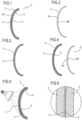
Figure 1 is a cross section of a first embodiment of the lens, which is not part of the claimed invention; -
Figure 2 shows the front glass wafer of the lens ofFigure 1 ; -
Figure 3 illustrates the front glass wafer ofFigure 2 , where the surface of the wafer is coloured; -
Figure 4 shows the rear glass wafer of the lens ofFigure 1 and the front glass wafer ofFigure 3 , with its concave surface in contact with the glue; -
Figure 5 shows the front and rear glass layers ofFigure 4 bonded to each other and subjected to a reticulating step; -
Figure 6 illustrates an enlarged detail of the lens ofFigure 1 ; -
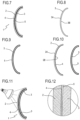
Figure 7 is a cross section of a second embodiment of the lens of the invention; -
Figure 8 shows the rear glass wafer of the lens ofFigure 7 ; -
Figure 9 illustrates the rear glass wafer ofFigure 8 , where the surface of the wafer is coloured; -
Figure 10 shows the rear glass wafer ofFigure 9 and the front glass wafer of the lens ofFigure 7 , with its concave surface in contact with the glue; -
Figure 11 shows the front and rear glass wafers ofFigure 10 bonded to each other and subjected to cross-linking; -
Figure 12 illustrates an enlarged detail of the lens ofFigure 7 ; -
Figure 13 schematically illustrates the lens ofFigure 1 in an exploded view; -
Figures 14-16 illustrate variant embodiments, not forming part of the claimed invention, of the lens ofFigure 13 ; -
Figure 17 schematically illustrates the lens ofFigure 7 in an exploded view; -
Figures 18-20 illustrate variant embodiments, some according to the claimed invention, of the lens ofFigure 17 . - The
numeral 1 in the drawings denotes a glass lens for eyeglasses. - The
lens 1 is a coloured lens. Preferably, thelens 1 is a (coloured and) colour gradient lens. - The
lens 1 comprises a first glass wafer 2 (hereinafter referred to as front wafer) and a second glass wafer 3 (hereinafter referred to as rear wafer). The glass used to make these wafers is preferably selected from one of the following types: - crown glass;
- glass able to provide UV protection;
- aluminosilicate, or alkali aluminosilicate, or borosilicate;
- glass containing rare earth elements (for example, neodymium); this glass can provide enhanced colour contrast;
- photochromic glass, that is, glass containing photochromic species (for example, silver halides) capable of producing colour and darkening the colour when exposed to activating radiation (UV or visible);
- glass capable of filtering infrared radiation, particularly in the range between 780 and 2000 nanometres.
- It should be noted that the glass of at least one of the
wafers - It should also be noted that the glass of the
wafers - Preferably, the UV protection is provided by UV filters which comprise UV absorbers. These absorbers may belong, for example, to the families of benzophenones, benzotriazoles, or derivatives thereof.
- Thus, the
lens 1 comprises afront glass wafer 2 having aconvex surface 2A and aconcave surface 2B. - The
lens 1 also comprises arear glass wafer 3 having aconvex surface 3A and aconcave surface 3B. - The
convex surface 3A of therear glass wafer 3 is face to face with (or contiguous with, or adjacent to) theconcave surface 2B of thefront glass wafer 2. - The
convex surface 3A of therear glass wafer 3 is bonded to theconcave surface 2B of thefront glass wafer 2 by a layer ofglue 4 interposed between them. - The layer of
glue 4 defines a UV screen (that is, a UV filter). - The layer of
glue 4 is interposed between thefront wafer 2 and therear wafer 3 in order to bond them to each other. - At least the
convex surface 3A of therear wafer 3 is coloured. - The
numeral 5 in the drawings denotes a coloured layer defined by at least one of the surfaces of at least one of thewafers coloured layer 5 is a surface layer (or portion) of one of thewafers -
Figure 1 illustrates a first embodiment not forming part of the claimed invention, where theconcave surface 2B of thefront wafer 2 is coloured.Figure 7 illustrates a second embodiment according to the claimed invention, where theconvex surface 3A of therear wafer 3 is coloured. - Preferably, the at least one coloured surface is colour graded.
- Preferably, the
front glass wafer 2 is photochromic, according to a technology of per se known type. - For example, the composition of the glass mass of the
front wafer 2 might comprise silver halides or other photochromic species. Alternatively, or in combination, a photochromic coating (for example containing spirooxazines or other organic photochromic species) might be applied to thefront wafer 2. - Preferably, the glue is a modified urethane, polyurethane, acrylic, epoxy or silicone glue. Preferably, it is a glue which can be cross-linked by UV irradiation, heat, humidity or a combination of these agents.
- Preferably, the
lens 1 does not have coloured polymeric layers. In particular, thelens 1 does not have glued coloured polymeric layers interposed between thefront glass wafer 2 and therear glass wafer 3. - In light of this, it should be noted that in one possible embodiment, a photochromic or dichroic polymeric film with polarizing properties (for example, polyvinyl alcohol) might be interposed between the two glass wafers.
- In the first embodiment not forming part of the claimed invention, where the
concave surface 2B of thefront wafer 2 is coloured, thefront wafer 2 preferably has a UV filter. - In the second embodiment according to the claimed invention, where the
convex surface 3A of therear wafer 3 is coloured, thefront wafer 2 does not have any UV filter (and, instead, the layer ofglue 4 defines a UV filter). - As regards the method for making the
lens 1 according to the invention, attention is drawn to the following. - The method comprises the following steps:
- preparing the
front glass wafer 2 and therear glass wafer 3; - colouring the
convex surface 3A of therear wafer 3; - depositing a predetermined quantity of glue to form the layer of glue 4 (constituting a UV screen) at an interface between the
concave surface 2B of thefront wafer 2 and theconvex surface 3A of therear wafer 3; - bonding the
rear wafer 3 and thefront wafer 2 to each other. - Preferably, the colouring step comprises applying a coat (by lacquering) to the surface of the glass wafer and dipping the coated (lacquered) surface to be coloured in a solution/dispersion containing colouring substances.
- The coating (lacquering) is done using either of two techniques, called dipping or spinning, (described in more detail below).
- Preferably, the colouring step comprises providing (at least) that surface with a colour gradient (or double colour gradient).
- The colouring step preferably comprises a preliminary step of lacquering the
glass wafer 3 to be coloured. - The next step is colouring proper (and preferably colour grading) the
wafer 3 to be coloured, or at least the surface of that wafer. - A glass lens is thus obtained which is coloured, or colour graded, or double-colour graded on both surfaces (if lacquering has been effected by "dipping") or on one surface only (if lacquering has been effected by "spinning" or using the equivalent techniques known as "flow-coating" or "spraying").
- To facilitate bonding between the
rear glass wafer 3 and thefront glass wafer 2 of thelens 1, the glue is subjected to a step of cross-linking. The cross-linking step comprises, for example, UV irradiation or application of heat or reaction with humidity, applied to the assembly consisting of the front andrear wafers glue 4 interposed between them, in order to cause the glue to become cross-linked. - In a first embodiment of the method not forming part of the claimed invention, the colouring is applied to the
concave surface 2B of thefront wafer 2. In this case, thefront glass wafer 2 defines a UV filter. - In a second embodiment of the method according to the invention, the colouring is applied to the
convex surface 3A of therear wafer 3. In this case, thefront glass wafer 2 is without UV filters. - The first embodiment not forming part of the invention is described in detail below with reference to
Figures 2 to 5 , in succession. - The first step is to lacquer the front wafer 2 (provided with UV filter).
- The
front wafer 2 is coloured after being lacquered, for example using the "dipping" method (in this case, both theconvex surface 2A and theconcave surface 2B of thefront wafer 2 are coloured), or using the "spinning" method (in this case, only theconcave surface 2B of thefront wafer 2 is coloured). - A
front glass wafer 2 is thus obtained which is coloured (preferably colour graded) on both surfaces or on one surface only. - Next, a predetermined quantity of glue is applied to form the layer of glue 4 (if necessary defining a UV filter) to the
concave surface 2B of thefront wafer 2. - The rear glass wafer 3 (which is preferably transparent, that is, not colour-coated but which might be mass-coloured in the case of contrast enhancement), preferably without UV filter, is then assembled to the
front wafer 2. - This sandwich, consisting of the two
glass wafers glue 4 interposed between them, is then subjected to a step of cross-linking the layer ofglue 4. - Thus, in the assembly (sandwich) consisting of the two
glass wafers glue 4 interposed between them, thecoloured surface 2B is a surface inside thelens 1 and is therefore protected by therear glass wafer 3. - If the colouring has been applied to the entire surface of the
front wafer 2, there is now a step of removing the colour from (that is, colour grading) theconvex surface 2A of the front wafer 2 (on the outside of the lens 1). - This step of removing the colour is not necessary if the colouring step (and more specifically, the preliminary lacquering step, that is, the application of the coating) is performed using the spinning, flow-coating or spraying methods.
- The second embodiment of the invention is described in detail below with reference to
Figures 8 to 11 , in succession. - The first step is to lacquer the
rear glass wafer 3. - The
rear wafer 3 is coloured after being lacquered, for example using the "dipping" method (in this case, both theconvex surface 3A and theconcave surface 3B of therear wafer 3 are coloured), or using the "spinning" method (in this case, only theconvex surface 3A of therear wafer 3 is coloured). - A
rear glass wafer 3 is thus obtained which is coloured (preferably colour graded) on both surfaces or on one surface only. - Next, a predetermined quantity of glue is applied to form the layer of glue 4 (defining a UV filter) to the
concave surface 2B of thefront wafer 2. - The coloured (or colour graded)
rear glass wafer 3 is then assembled to thefront wafer 2. - This sandwich, consisting of the two
glass wafers glue 4 interposed between them, is then subjected to a step of cross-linking the layer ofglue 4. - Thus, in the assembly (sandwich) consisting of the two
glass wafers glue 4 interposed between them, thecoloured surface 3A is a surface inside thelens 1 and is therefore protected by thefront glass wafer 2. - If the colouring has been applied to the entire surface of the
rear wafer 3, there is now a step of removing the colour from (that is, colour grading) theconcave surface 3B of the rear wafer 3 (on the outside of the lens 1). - This step of removing the colour is not necessary if the colouring step is performed using methods which can be applied directly on a single face, for example the methods known as spinning, flow-coating or spraying.
- At least one of the
wafers lens 1 might comprise a polarized film interposed between theglass wafers lens 1 which is polarized and at once coloured or colour graded or double colour graded. - To give the
lens 1 the polarizing property, the following two approaches can be adopted, individually or in combination. - According to the first approach, a polarized dichroic coating is applied to the surface without colouring, which is the
concave surface 2B of the front wafer 2 (second variant embodiment) - In the second approach, a polarized film is interposed between the
concave surface 2B of thefront wafer 2 and theconvex surface 3A of therear wafer 3. - The polarized film - made for example of poly(vinyl alcohol) - is preferably a precurved, solid polymeric film which needs glue on both sides so as to adhere to both the
concave surface 2B of thefront wafer 2 and theconvex surface 3A of therear wafer 3. Thus, in this configuration, the lens comprises two layers of glue. - Preferably, in this case, a predetermined quantity of glue is applied to the
concave surface 2B of thefront wafer 2 and on a concave surface of the polarized film (which is curved and therefore forms a concave surface and a convex surface). - To give the
lens 1 the photochromic property, the following two approaches can be adopted, individually or in combination (although other approaches are possible, such as, for example, the use of glass with silver halides added to it, as mentioned above). - According to the first approach, a photochromic coating is applied to the surface without the
coloured coating 5, which is theconcave surface 2B of the front wafer 2 (second variant embodiment). - In the second approach, a photochromic film is interposed between the
concave surface 2B of thefront wafer 2 and theconvex surface 3A of therear wafer 3. - The photochromic film needs glue on both sides so as to adhere to both the
concave surface 2B of thefront wafer 2 and theconvex surface 3A of therear wafer 3. Thus, in this configuration, the lens comprises two layers of glue (as described in connection with the polarized film). - The
lens 1 is illustrated schematically inFigure 13 (in the first embodiment not forming part of the claimed invention, where theconcave surface 2B of thefront wafer 2 is coloured) and inFigure 17 (in the second embodiment, where theconvex surface 3A of therear wafer 3 is coloured). - In these figures, the
numeral 6 denotes a front coating of thelens 1, created by a mirror treatment and/or a hydrophobic treatment of thelens 1. The treatment involves theconvex surface 2A of thefront glass wafer 2. Thus, thefront coating 6 is applied to theconvex surface 2A of thefront glass wafer 2. - Thus, the
lens 1 preferably comprises thefront coating 6, which has reflective and/or hydrophobic properties. - Further, the
lens 1 preferably comprises arear coating 7, which has anti-glare and/or hydrophobic properties. - The
rear coating 7 is created by an anti-glare treatment and/or a hydrophobic treatment of thelens 1. The treatment involves theconcave surface 3B of therear glass wafer 3. - Thus, the
rear coating 7 is applied to theconcave surface 3B of therear glass wafer 3. - The front and
rear coatings lens 1 irrespective of whether colouring is applied according to the first embodiment or the second. - Further, it should be noted that the
numeral 8 inFigures 13-20 denotes a quantity of glue which is schematically represented in order to indicate the position where the layer ofglue 4 is when thelens 1 is assembled. - It should be noted that the
coloured layer 5 is a coating made (on theconcave surface 2B of thefront glass wafer 2 or on theconvex surface 3A of the rear glass wafer 3) by lacquering and then impregnated with colour. - Thus, the
coloured layer 5 is a coloured or colour graded coating. The coating is an internal coating, in the sense that it is interposed between theglass wafers - Preferably, the
lens 1 comprises an additionalinternal coating 9 having polarizing and/or photochromic properties. - The additional
internal coating 9 is applied to theconcave surface 2B of thefront glass wafer 2 or to theconvex surface 3A of therear glass wafer 3 which is without the coloured coating, that is, without thecoloured layer 5. - Thus, in the first embodiment not forming part of the claimed invention, where the
concave surface 2B of thefront wafer 2 is coloured, the additionalinternal coating 9 is applied to theconvex surface 3A of therear glass wafer 3, whereas in the second embodiment, where theconvex surface 3A of therear wafer 3 is coloured, the additionalinternal coating 9 is applied to theconcave surface 2B of thefront wafer 2. - Preferably, the
lens 1 also comprises a polarized orphotochromic film 10. The polarized or photochromic 10 film is precurved. - Preferably (but not necessarily), the polarized or
photochromic film 10 is used when there is no additionalinternal coating 9. - The polarized or
photochromic film 10 consists of a polymeric substrate especially treated or with suitable additives; that is to say, the polarized orphotochromic film 10 is made from a thin polymeric film which is treated (according to a method of per se known type) to obtain the desired polarizing or photochromic property. - The polarized or
photochromic film 10 is located inside thelens 1, between two layers ofglue 4. In effect, the polarized orphotochromic film 10 is not a coating but a separate film which must be bonded by adhesive means to theconcave surface 2B of the front glass wafer 2 (where theconcave surface 2B may or may not be coated with thecoloured layer 5 or the additional internal coating 9) and to theconvex surface 3A of the rear glass wafer 3 (where theconvex surface 3A may or may not be coated with thecoloured layer 5 or the additional internal coating 9). - Thus (in a possible embodiment), the
lens 1 might comprise the polarized orphotochromic film 10 interposed between two layers ofglue 4. - It should be noted that if the polarized or
photochromic film 10 is not present, thelens 1 is preferably without glued polymeric layers (or films). Below is a brief description of the eight variant embodiments of thelens 1, illustrated inFigures 13-20 , with reference to these figures by way of example: -
lens 1 according to the first embodiment not forming part of the claimed invention, that is, where thecoloured layer 5 is a coating of theconcave surface 2B of thefront glass wafer 2; this lens does not have the additionalinternal coating 9 and the polarized and photochromic film 10 (Figure 13 ); -
lens 1 according to the first embodiment not forming part of the claimed invention, without the additionalinternal coating 9 and comprising the polarized and photochromic film 10 (Figure 14 ); -
lens 1 according to the first embodiment not forming part of the claimed invention, comprising the additionalinternal coating 9 and without the polarized and photochromic film 10 (Figure 15 ); -
lens 1 according to the first embodiment not forming part of the claimed invention, comprising both the additionalinternal coating 9 and the polarized and photochromic film 10 (Figure 16 ); -
lens 1 according to the second embodiment, that is, where thecoloured layer 5 is a coating of theconvex surface 3A of therear glass wafer 3; this lens does not have the additional internal coating 9 (and therefore also does not form part of the claimed invention) or the polarized and photochromic film 10 (Figure 17 ); -
lens 1 according to the second embodiment, without the additional internal coating 9 (and therefore also not forming part of the claimed invention) but comprising the polarized and photochromic film 10 (Figure 18 ); -
lens 1 according to the claimed invention, comprising the additionalinternal coating 9 but without the polarized and photochromic film 10 (Figure 19 ); -
lens 1 according to the claimed invention, comprising both the additionalinternal coating 9 and the polarized and photochromic film 10 (Figure 20 ). - In these example embodiments (described briefly above with reference to
Figures 13-20 ), the lens always comprises thefront coating 6 and therear coating 7. It should be noted, however, that thelens 1 might be without thefront coating 6 and/or without therear coating 7, and that this applies to all the example embodiments listed. - The lens according to the invention has numerous advantages.
- First of all, it is quick and easy to make.
- Also, the colouring is durable and robust.
- Also, the invention allows a wide variety of colours and colour gradients to be obtained.
- The invention also makes it possible to give the lens a wide variety of optical properties or functions (in combination with the colouring and colour gradient), depending on the type of glass used (for example, the glass might be: uncoloured, coloured, with UV protection, with rare earth elements for enhanced contrast, with high impact strength), on the functional coating which may be applied (polarized and/or photochromic), on the presence of a film which may, if necessary, be interposed between the glass wafers (polarized and/or photochromic) and on external surface treatments, if any, such as for example, mirroring, anti-glare, hydrophobicity or any combination or subset of these), within the limits laid down by regulations applicable to the trade.
- Another advantage of this invention compared to lenses made with the PVD method is its increased durability of the sensitive coloured surface, which is protected between two glass wafers and cannot therefore be removed by abrasion. Coatings applied by PVD, on the other hand, however resistant they may be, are significantly more prone to scratching during normal use.
Claims (11)
- A coloured glass lens (1) for eyeglasses, the coloured glass lens (1) comprising a front glass wafer (2) and a rear glass wafer (3) having a convex surface (3A) connected to a concave surface (2B) of the front wafer (2), wherein at least the convex surface (3A) of the rear wafer (3) has a coloured coating (5), the lens (1) comprising a layer of glue (4) interposed between said surfaces (2B, 3A) for bonding the front and rear wafers (2, 3) to each other, the layer of glue (4) defining a filter as a screen against UV radiation, and the concave surface (2B) of the front wafer (2) having a polarized or photochromic coating (9), and wherein the coloured coating (5) comprises a layer of lacquer impregnated with pigment, characterised in that the coloured coating (5) is made by applying a cross-linked coating and then colouring it.
- The lens according to claim 1, wherein the coloured coating (5) is colour graded.
- The lens according to any of the preceding claims, wherein the glue is a modified urethane, polyurethane, acrylic, epoxy or silicone glue.
- The lens according to any of the preceding claims, wherein the front wafer (2) is without UV filters.
- The lens according to any of the preceding claims, wherein the lens (1) does not have any glued coloured polymeric layers.
- The lens according to any of the preceding claims, comprising:- a polarized or photochromic film (10) interposed between the convex surface (3A) of the rear glass wafer (3) and the concave surface (2B) of the front glass wafer (2); and- a first layer of glue (4) interposed between the polarized or photochromic film (10) and the convex surface (3A) of the rear glass wafer (3), and a second layer of glue (4) interposed between the polarized or photochromic film (10) and the concave surface (2B) of the front glass wafer (2).
- A method for making a coloured glass lens (1 ) for eyeglasses, the method comprising a step of connecting a front glass wafer (2) and a rear glass wafer (3) at an interface between a convex surface (3A) of the rear wafer (3) and a concave surface (2B) of the front wafer (2), the step of connecting comprising the following steps:- colouring at least the convex surface (3A) of the rear wafer (3) by applying a coloured coating (5) on said convex surface (3A);- applying a layer of glue (4) at the interface, the layer of glue (4) defining a filter as a screen against UV rays;- applying a polarized or photochromic coating (9); and- bonding the rear wafer (3) and the front wafer (2) to each other, the polarized or photochromic coating (9) being applied on the concave surface (2B) of the front wafer (2),wherein the step of colouring comprises the following steps:- lacquering the rear glass wafer (3) to form a coating on the convex surface (3A) of the rear wafer (3),- cross-linking the lacquer applied uniformly using an external agent, and- impregnating the coating with a liquid in which pigments are dissolved, in order to form the coloured coating (5),characterised in that the impregnation of the coating with the liquid is performed after lacquering the rear glass wafer (3) and cross-linking the lacquer.
- The method according to claim 7, wherein the colouring step comprises colour grading the coloured coating (5).
- The method according to claim 7 or 8, wherein bonding the rear wafer (3) and the front wafer (2) to each other comprises a step of cross- linking the layer of glue (4).
- The method according to any of the claims from 7 to 9, the front glass wafer (2) being without UV filters.
- The method according to any of the claims from 7 to 10, comprising a step of gluing a polarized or photochromic film (10) between the convex surface (3A) of the rear glass wafer (3) and the concave surface (2B) of the front glass wafer (2), by means of a first and a second layer of glue (4), respectively.
Applications Claiming Priority (2)
| Application Number | Priority Date | Filing Date | Title |
|---|---|---|---|
| IT000437A ITBO20120437A1 (en) | 2012-08-07 | 2012-08-07 | GLASS LENS FOR COLORED GLASSES AND A METHOD OF REALIZING IT. |
| PCT/IB2013/055862 WO2014024065A1 (en) | 2012-08-07 | 2013-07-17 | Coloured glass lens for eyeglasses and method for making it |
Publications (2)
| Publication Number | Publication Date |
|---|---|
| EP2883106A1 EP2883106A1 (en) | 2015-06-17 |
| EP2883106B1 true EP2883106B1 (en) | 2025-07-09 |
Family
ID=46939751
Family Applications (1)
| Application Number | Title | Priority Date | Filing Date |
|---|---|---|---|
| EP13767093.1A Active EP2883106B1 (en) | 2012-08-07 | 2013-07-17 | Coloured glass lens for eyeglasses and method for making it |
Country Status (5)
| Country | Link |
|---|---|
| US (1) | US10732436B2 (en) |
| EP (1) | EP2883106B1 (en) |
| CN (1) | CN104520757B (en) |
| IT (1) | ITBO20120437A1 (en) |
| WO (1) | WO2014024065A1 (en) |
Families Citing this family (20)
| Publication number | Priority date | Publication date | Assignee | Title |
|---|---|---|---|---|
| US8770749B2 (en) | 2010-04-15 | 2014-07-08 | Oakley, Inc. | Eyewear with chroma enhancement |
| CA3090848A1 (en) | 2011-10-20 | 2013-05-16 | Oakley, Inc. | Eyewear with chroma enhancement |
| WO2013169987A1 (en) | 2012-05-10 | 2013-11-14 | Oakley, Inc. | Eyewear with laminated functional layers |
| ITBO20120437A1 (en) * | 2012-08-07 | 2014-02-08 | Luxottica Srl | GLASS LENS FOR COLORED GLASSES AND A METHOD OF REALIZING IT. |
| US9575335B1 (en) | 2014-01-10 | 2017-02-21 | Oakley, Inc. | Eyewear with chroma enhancement for specific activities |
| US9372353B2 (en) * | 2014-03-05 | 2016-06-21 | Distributed Polarization Inc. | Method and apparatus for forming sunglass lenses with a predetermined gradient |
| US9977262B2 (en) * | 2014-03-12 | 2018-05-22 | Honeywell International, Inc. | Electrochromic lenses and methods of fabricating the same |
| CN207704150U (en) | 2014-11-13 | 2018-08-07 | 奥克利有限公司 | Variable light attenuating eyewear with color enhancement |
| EP3312662B1 (en) * | 2016-10-21 | 2019-07-17 | Carl Zeiss Vision International GmbH | Brillenglas und verfahren zu dessen herstellung |
| US11673355B2 (en) | 2016-12-23 | 2023-06-13 | Transitions Optical, Ltd. | Method of manufacture of a lens with gradient properties using imbibition technology |
| TWI655475B (en) * | 2017-02-08 | 2019-04-01 | 和昇眼鏡企業股份有限公司 | Anti-glare dissipating optical lens |
| US12124116B2 (en) | 2017-10-20 | 2024-10-22 | Luxottica S.R.L. | Eyewear with variable transmission lens |
| US10543577B2 (en) | 2018-01-23 | 2020-01-28 | Clear and Dark Ltd. | Systems, methods, and apparatus for forming optical articles, and optical articles formed by the same |
| US11112622B2 (en) | 2018-02-01 | 2021-09-07 | Luxottica S.R.L. | Eyewear and lenses with multiple molded lens components |
| SG11202009885XA (en) * | 2018-04-12 | 2020-11-27 | Tokuyama Corp | Photochromic optical article and method for manufacturing same |
| EP3556735A1 (en) | 2018-04-20 | 2019-10-23 | Barberini GmbH | Contrast enhancing glass for sunglass lenses |
| CN109307938A (en) * | 2018-11-30 | 2019-02-05 | 厦门立扬光学科技有限公司 | UV resistant glass lens |
| JP2022151409A (en) * | 2021-03-25 | 2022-10-07 | 株式会社トクヤマ | photochromic optical article |
| DE102022104556B4 (en) * | 2022-02-25 | 2025-02-27 | Rodenstock Gmbh | Method for providing a substrate with a coloring and a functional coloring on one side |
| CN119773320A (en) * | 2024-12-26 | 2025-04-08 | 珠海华尚汽车玻璃工业有限公司 | A preparation process and structure of a riot-proof front windshield for a vehicle |
Citations (3)
| Publication number | Priority date | Publication date | Assignee | Title |
|---|---|---|---|---|
| EP0797786B1 (en) * | 1994-12-16 | 2006-02-08 | Sola International Holdings, Ltd. | Incorporating photochromic molecules in light transmissible articles |
| WO2011105211A1 (en) * | 2010-02-25 | 2011-09-01 | タレックス光学工業株式会社 | Laminated glass lens for glasses |
| ITBO20120437A1 (en) * | 2012-08-07 | 2014-02-08 | Luxottica Srl | GLASS LENS FOR COLORED GLASSES AND A METHOD OF REALIZING IT. |
Family Cites Families (11)
| Publication number | Priority date | Publication date | Assignee | Title |
|---|---|---|---|---|
| AUPN718195A0 (en) * | 1995-12-18 | 1996-01-18 | Sola International Holdings Ltd | Laminate wafers |
| US6793339B1 (en) * | 1997-10-21 | 2004-09-21 | Sola-International Holdings, Ltd. | Coated sunglass lens |
| US6604824B2 (en) * | 1998-02-23 | 2003-08-12 | Charles P. Larson | Polarized lens with oxide additive |
| US20040174493A1 (en) | 2003-03-07 | 2004-09-09 | Chen Yau Ming | Multi-function shatter-proof safety eyewear glass lens |
| US20050109458A1 (en) * | 2003-11-21 | 2005-05-26 | D'herbecourt Bruno | Method of bonding two materials with a crosslinkable adhesive |
| US9377569B2 (en) * | 2006-03-20 | 2016-06-28 | High Performance Optics, Inc. | Photochromic ophthalmic systems that selectively filter specific blue light wavelengths |
| ITBO20070721A1 (en) | 2007-10-26 | 2009-04-27 | Luxottica Srl | SHADED LENS. |
| ITBO20070722A1 (en) | 2007-10-26 | 2009-04-27 | Luxottica Srl | METHOD OF PRODUCTION OF SHADED LENSES AND SHADED LENSES OBTAINED. |
| US8210678B1 (en) * | 2009-12-21 | 2012-07-03 | Farwig Michael J | Multiband contrast-enhancing light filter and polarized sunglass lens comprising same |
| US8770749B2 (en) * | 2010-04-15 | 2014-07-08 | Oakley, Inc. | Eyewear with chroma enhancement |
| US8748767B2 (en) * | 2011-05-27 | 2014-06-10 | Dell Products Lp | Sub-membrane keycap indicator |
-
2012
- 2012-08-07 IT IT000437A patent/ITBO20120437A1/en unknown
-
2013
- 2013-07-17 CN CN201380042101.9A patent/CN104520757B/en active Active
- 2013-07-17 EP EP13767093.1A patent/EP2883106B1/en active Active
- 2013-07-17 WO PCT/IB2013/055862 patent/WO2014024065A1/en not_active Ceased
- 2013-07-17 US US14/419,596 patent/US10732436B2/en active Active
Patent Citations (4)
| Publication number | Priority date | Publication date | Assignee | Title |
|---|---|---|---|---|
| EP0797786B1 (en) * | 1994-12-16 | 2006-02-08 | Sola International Holdings, Ltd. | Incorporating photochromic molecules in light transmissible articles |
| WO2011105211A1 (en) * | 2010-02-25 | 2011-09-01 | タレックス光学工業株式会社 | Laminated glass lens for glasses |
| US20120287395A1 (en) * | 2010-02-25 | 2012-11-15 | Kanichi Tamura | Laminated glass lens for spectacles |
| ITBO20120437A1 (en) * | 2012-08-07 | 2014-02-08 | Luxottica Srl | GLASS LENS FOR COLORED GLASSES AND A METHOD OF REALIZING IT. |
Also Published As
| Publication number | Publication date |
|---|---|
| US10732436B2 (en) | 2020-08-04 |
| ITBO20120437A1 (en) | 2014-02-08 |
| EP2883106A1 (en) | 2015-06-17 |
| CN104520757A (en) | 2015-04-15 |
| CN104520757B (en) | 2017-10-20 |
| US20150219931A1 (en) | 2015-08-06 |
| WO2014024065A1 (en) | 2014-02-13 |
Similar Documents
| Publication | Publication Date | Title |
|---|---|---|
| US10732436B2 (en) | Coloured glass lens for eyeglasses and method for making it | |
| US11579470B2 (en) | Lens with anti-fog element | |
| CN207752263U (en) | Laminated Mirror Lenses and Eyewear | |
| US5928718A (en) | Protective coating for reflective sunglasses | |
| US20200363659A1 (en) | Multilayer photochromic laminate | |
| CN114384713A (en) | Lenses for Sunglasses | |
| US11474381B2 (en) | Ophthalmic article | |
| CN105572770B (en) | Antireflection film used in blue-light-proof spectacle lens | |
| AU2017301860B2 (en) | Ophthalmic lens in particular for sunglasses | |
| US11067828B2 (en) | Eyewear lens or optical film with decorative dichromic mirror pattern having variable opacity | |
| WO2019145391A1 (en) | Photochromic optically transparent electrically conductive film laminate | |
| AU2010333253A1 (en) | Photochromic optical article comprising a saturated photochromic coating and a film absorbing UV radiation | |
| JP2012523974A (en) | Method for manufacturing dimming optical element and dimming optical element | |
| TWM566341U (en) | Three-dimensional (3D) anti-fog lens | |
| JP6231373B2 (en) | Wire grid polarizing lens with antireflection function | |
| CN114521244B (en) | Ophthalmic lens, method of manufacturing the same, and eyewear comprising an ophthalmic lens | |
| CN111367092A (en) | Anti-ultraviolet photochromic spectacle lens and preparation method thereof | |
| CN212846202U (en) | Antifog photochromic resin lens | |
| KR102954871B1 (en) | Reflective keyring doll with retroreflective function | |
| TWI917759B (en) | Manufacturing method and finished product of gradient photochromic lenses | |
| CN216748305U (en) | Glasses with compound TAC material lens | |
| EP3936927A1 (en) | Method for tinting an ophtalmic article and related ophtalmic article | |
| TWM517540U (en) | Helmet with color chnageable windshield/goggle | |
| CA2285612A1 (en) | Coated sunglass lens | |
| KR20060067450A (en) | Manufacturing method of polarizing composite and polarizing composite manufactured by the method |
Legal Events
| Date | Code | Title | Description |
|---|---|---|---|
| PUAI | Public reference made under article 153(3) epc to a published international application that has entered the european phase |
Free format text: ORIGINAL CODE: 0009012 |
|
| 17P | Request for examination filed |
Effective date: 20150224 |
|
| AK | Designated contracting states |
Kind code of ref document: A1 Designated state(s): AL AT BE BG CH CY CZ DE DK EE ES FI FR GB GR HR HU IE IS IT LI LT LU LV MC MK MT NL NO PL PT RO RS SE SI SK SM TR |
|
| AX | Request for extension of the european patent |
Extension state: BA ME |
|
| DAX | Request for extension of the european patent (deleted) | ||
| STAA | Information on the status of an ep patent application or granted ep patent |
Free format text: STATUS: EXAMINATION IS IN PROGRESS |
|
| 17Q | First examination report despatched |
Effective date: 20190515 |
|
| P01 | Opt-out of the competence of the unified patent court (upc) registered |
Effective date: 20230511 |
|
| GRAP | Despatch of communication of intention to grant a patent |
Free format text: ORIGINAL CODE: EPIDOSNIGR1 |
|
| STAA | Information on the status of an ep patent application or granted ep patent |
Free format text: STATUS: GRANT OF PATENT IS INTENDED |
|
| RIC1 | Information provided on ipc code assigned before grant |
Ipc: B29D 11/00 20060101ALI20241115BHEP Ipc: G02C 7/12 20060101ALI20241115BHEP Ipc: G02C 7/10 20060101AFI20241115BHEP |
|
| INTG | Intention to grant announced |
Effective date: 20241202 |
|
| GRAJ | Information related to disapproval of communication of intention to grant by the applicant or resumption of examination proceedings by the epo deleted |
Free format text: ORIGINAL CODE: EPIDOSDIGR1 |
|
| STAA | Information on the status of an ep patent application or granted ep patent |
Free format text: STATUS: EXAMINATION IS IN PROGRESS |
|
| GRAP | Despatch of communication of intention to grant a patent |
Free format text: ORIGINAL CODE: EPIDOSNIGR1 |
|
| STAA | Information on the status of an ep patent application or granted ep patent |
Free format text: STATUS: GRANT OF PATENT IS INTENDED |
|
| INTC | Intention to grant announced (deleted) | ||
| RIN1 | Information on inventor provided before grant (corrected) |
Inventor name: GRASSO, OMAR |
|
| INTG | Intention to grant announced |
Effective date: 20250306 |
|
| RAP3 | Party data changed (applicant data changed or rights of an application transferred) |
Owner name: LUXOTTICA S.R.L. |
|
| GRAS | Grant fee paid |
Free format text: ORIGINAL CODE: EPIDOSNIGR3 |
|
| GRAA | (expected) grant |
Free format text: ORIGINAL CODE: 0009210 |
|
| STAA | Information on the status of an ep patent application or granted ep patent |
Free format text: STATUS: THE PATENT HAS BEEN GRANTED |
|
| AK | Designated contracting states |
Kind code of ref document: B1 Designated state(s): AL AT BE BG CH CY CZ DE DK EE ES FI FR GB GR HR HU IE IS IT LI LT LU LV MC MK MT NL NO PL PT RO RS SE SI SK SM TR |
|
| REG | Reference to a national code |
Ref country code: GB Ref legal event code: FG4D |
|
| REG | Reference to a national code |
Ref country code: CH Ref legal event code: EP |
|
| REG | Reference to a national code |
Ref country code: IE Ref legal event code: FG4D |
|
| REG | Reference to a national code |
Ref country code: DE Ref legal event code: R096 Ref document number: 602013086882 Country of ref document: DE |
|
| PGFP | Annual fee paid to national office [announced via postgrant information from national office to epo] |
Ref country code: DE Payment date: 20250729 Year of fee payment: 13 |
|
| PGFP | Annual fee paid to national office [announced via postgrant information from national office to epo] |
Ref country code: IT Payment date: 20250919 Year of fee payment: 13 |
|
| PGFP | Annual fee paid to national office [announced via postgrant information from national office to epo] |
Ref country code: FR Payment date: 20250725 Year of fee payment: 13 |
|
| REG | Reference to a national code |
Ref country code: NL Ref legal event code: MP Effective date: 20250709 |
|
| PG25 | Lapsed in a contracting state [announced via postgrant information from national office to epo] |
Ref country code: PT Free format text: LAPSE BECAUSE OF FAILURE TO SUBMIT A TRANSLATION OF THE DESCRIPTION OR TO PAY THE FEE WITHIN THE PRESCRIBED TIME-LIMIT Effective date: 20251110 |
|
| PG25 | Lapsed in a contracting state [announced via postgrant information from national office to epo] |
Ref country code: NL Free format text: LAPSE BECAUSE OF FAILURE TO SUBMIT A TRANSLATION OF THE DESCRIPTION OR TO PAY THE FEE WITHIN THE PRESCRIBED TIME-LIMIT Effective date: 20250709 |
|
| REG | Reference to a national code |
Ref country code: AT Ref legal event code: MK05 Ref document number: 1812361 Country of ref document: AT Kind code of ref document: T Effective date: 20250709 |
|
| PG25 | Lapsed in a contracting state [announced via postgrant information from national office to epo] |
Ref country code: IS Free format text: LAPSE BECAUSE OF FAILURE TO SUBMIT A TRANSLATION OF THE DESCRIPTION OR TO PAY THE FEE WITHIN THE PRESCRIBED TIME-LIMIT Effective date: 20251109 |
|
| PG25 | Lapsed in a contracting state [announced via postgrant information from national office to epo] |
Ref country code: NO Free format text: LAPSE BECAUSE OF FAILURE TO SUBMIT A TRANSLATION OF THE DESCRIPTION OR TO PAY THE FEE WITHIN THE PRESCRIBED TIME-LIMIT Effective date: 20251009 |
|
| REG | Reference to a national code |
Ref country code: LT Ref legal event code: MG9D |
|
| PG25 | Lapsed in a contracting state [announced via postgrant information from national office to epo] |
Ref country code: AT Free format text: LAPSE BECAUSE OF FAILURE TO SUBMIT A TRANSLATION OF THE DESCRIPTION OR TO PAY THE FEE WITHIN THE PRESCRIBED TIME-LIMIT Effective date: 20250709 |
|
| PG25 | Lapsed in a contracting state [announced via postgrant information from national office to epo] |
Ref country code: FI Free format text: LAPSE BECAUSE OF FAILURE TO SUBMIT A TRANSLATION OF THE DESCRIPTION OR TO PAY THE FEE WITHIN THE PRESCRIBED TIME-LIMIT Effective date: 20250709 |
|
| PG25 | Lapsed in a contracting state [announced via postgrant information from national office to epo] |
Ref country code: HR Free format text: LAPSE BECAUSE OF FAILURE TO SUBMIT A TRANSLATION OF THE DESCRIPTION OR TO PAY THE FEE WITHIN THE PRESCRIBED TIME-LIMIT Effective date: 20250709 |
|
| PG25 | Lapsed in a contracting state [announced via postgrant information from national office to epo] |
Ref country code: GR Free format text: LAPSE BECAUSE OF FAILURE TO SUBMIT A TRANSLATION OF THE DESCRIPTION OR TO PAY THE FEE WITHIN THE PRESCRIBED TIME-LIMIT Effective date: 20251010 |
|
| PG25 | Lapsed in a contracting state [announced via postgrant information from national office to epo] |
Ref country code: SE Free format text: LAPSE BECAUSE OF FAILURE TO SUBMIT A TRANSLATION OF THE DESCRIPTION OR TO PAY THE FEE WITHIN THE PRESCRIBED TIME-LIMIT Effective date: 20250709 |
|
| PG25 | Lapsed in a contracting state [announced via postgrant information from national office to epo] |
Ref country code: LV Free format text: LAPSE BECAUSE OF FAILURE TO SUBMIT A TRANSLATION OF THE DESCRIPTION OR TO PAY THE FEE WITHIN THE PRESCRIBED TIME-LIMIT Effective date: 20250709 |
|
| PG25 | Lapsed in a contracting state [announced via postgrant information from national office to epo] |
Ref country code: BG Free format text: LAPSE BECAUSE OF FAILURE TO SUBMIT A TRANSLATION OF THE DESCRIPTION OR TO PAY THE FEE WITHIN THE PRESCRIBED TIME-LIMIT Effective date: 20250709 Ref country code: PL Free format text: LAPSE BECAUSE OF FAILURE TO SUBMIT A TRANSLATION OF THE DESCRIPTION OR TO PAY THE FEE WITHIN THE PRESCRIBED TIME-LIMIT Effective date: 20250709 |
|
| PG25 | Lapsed in a contracting state [announced via postgrant information from national office to epo] |
Ref country code: RS Free format text: LAPSE BECAUSE OF FAILURE TO SUBMIT A TRANSLATION OF THE DESCRIPTION OR TO PAY THE FEE WITHIN THE PRESCRIBED TIME-LIMIT Effective date: 20251009 |
|
| REG | Reference to a national code |
Ref country code: CH Ref legal event code: W10 Free format text: ST27 STATUS EVENT CODE: U-0-0-W10-W00 (AS PROVIDED BY THE NATIONAL OFFICE) Effective date: 20260128 |
|
| PG25 | Lapsed in a contracting state [announced via postgrant information from national office to epo] |
Ref country code: ES Free format text: LAPSE BECAUSE OF FAILURE TO SUBMIT A TRANSLATION OF THE DESCRIPTION OR TO PAY THE FEE WITHIN THE PRESCRIBED TIME-LIMIT Effective date: 20250709 |
|
| REG | Reference to a national code |
Ref country code: CH Ref legal event code: H13 Free format text: ST27 STATUS EVENT CODE: U-0-0-H10-H13 (AS PROVIDED BY THE NATIONAL OFFICE) Effective date: 20260224 |
|
| RAP4 | Party data changed (patent owner data changed or rights of a patent transferred) |
Owner name: LUXOTTICA S.R.L. |
|
| PG25 | Lapsed in a contracting state [announced via postgrant information from national office to epo] |
Ref country code: LU Free format text: LAPSE BECAUSE OF NON-PAYMENT OF DUE FEES Effective date: 20250717 Ref country code: RO Free format text: LAPSE BECAUSE OF FAILURE TO SUBMIT A TRANSLATION OF THE DESCRIPTION OR TO PAY THE FEE WITHIN THE PRESCRIBED TIME-LIMIT Effective date: 20250709 |
|
| REG | Reference to a national code |
Ref country code: BE Ref legal event code: MM Effective date: 20250731 |
|
| PG25 | Lapsed in a contracting state [announced via postgrant information from national office to epo] |
Ref country code: SM Free format text: LAPSE BECAUSE OF FAILURE TO SUBMIT A TRANSLATION OF THE DESCRIPTION OR TO PAY THE FEE WITHIN THE PRESCRIBED TIME-LIMIT Effective date: 20250709 |
|
| PG25 | Lapsed in a contracting state [announced via postgrant information from national office to epo] |
Ref country code: DK Free format text: LAPSE BECAUSE OF FAILURE TO SUBMIT A TRANSLATION OF THE DESCRIPTION OR TO PAY THE FEE WITHIN THE PRESCRIBED TIME-LIMIT Effective date: 20250709 |
|
| PG25 | Lapsed in a contracting state [announced via postgrant information from national office to epo] |
Ref country code: BE Free format text: LAPSE BECAUSE OF NON-PAYMENT OF DUE FEES Effective date: 20250731 |
|
| PG25 | Lapsed in a contracting state [announced via postgrant information from national office to epo] |
Ref country code: CH Free format text: LAPSE BECAUSE OF NON-PAYMENT OF DUE FEES Effective date: 20250731 Ref country code: CZ Free format text: LAPSE BECAUSE OF FAILURE TO SUBMIT A TRANSLATION OF THE DESCRIPTION OR TO PAY THE FEE WITHIN THE PRESCRIBED TIME-LIMIT Effective date: 20250709 |
|
| PG25 | Lapsed in a contracting state [announced via postgrant information from national office to epo] |
Ref country code: SK Free format text: LAPSE BECAUSE OF FAILURE TO SUBMIT A TRANSLATION OF THE DESCRIPTION OR TO PAY THE FEE WITHIN THE PRESCRIBED TIME-LIMIT Effective date: 20250709 Ref country code: EE Free format text: LAPSE BECAUSE OF FAILURE TO SUBMIT A TRANSLATION OF THE DESCRIPTION OR TO PAY THE FEE WITHIN THE PRESCRIBED TIME-LIMIT Effective date: 20250709 |
|
| PLBE | No opposition filed within time limit |
Free format text: ORIGINAL CODE: 0009261 |
|
| STAA | Information on the status of an ep patent application or granted ep patent |
Free format text: STATUS: NO OPPOSITION FILED WITHIN TIME LIMIT |