EP2882883B1 - Terminal for mechanical support of a heating element - Google Patents
Terminal for mechanical support of a heating element Download PDFInfo
- Publication number
- EP2882883B1 EP2882883B1 EP13752822.0A EP13752822A EP2882883B1 EP 2882883 B1 EP2882883 B1 EP 2882883B1 EP 13752822 A EP13752822 A EP 13752822A EP 2882883 B1 EP2882883 B1 EP 2882883B1
- Authority
- EP
- European Patent Office
- Prior art keywords
- heating element
- terminal
- support
- support device
- mounting device
- Prior art date
- Legal status (The legal status is an assumption and is not a legal conclusion. Google has not performed a legal analysis and makes no representation as to the accuracy of the status listed.)
- Active
Links
Images


Classifications
-
- C—CHEMISTRY; METALLURGY
- C23—COATING METALLIC MATERIAL; COATING MATERIAL WITH METALLIC MATERIAL; CHEMICAL SURFACE TREATMENT; DIFFUSION TREATMENT OF METALLIC MATERIAL; COATING BY VACUUM EVAPORATION, BY SPUTTERING, BY ION IMPLANTATION OR BY CHEMICAL VAPOUR DEPOSITION, IN GENERAL; INHIBITING CORROSION OF METALLIC MATERIAL OR INCRUSTATION IN GENERAL
- C23C—COATING METALLIC MATERIAL; COATING MATERIAL WITH METALLIC MATERIAL; SURFACE TREATMENT OF METALLIC MATERIAL BY DIFFUSION INTO THE SURFACE, BY CHEMICAL CONVERSION OR SUBSTITUTION; COATING BY VACUUM EVAPORATION, BY SPUTTERING, BY ION IMPLANTATION OR BY CHEMICAL VAPOUR DEPOSITION, IN GENERAL
- C23C16/00—Chemical coating by decomposition of gaseous compounds, without leaving reaction products of surface material in the coating, i.e. chemical vapour deposition [CVD] processes
- C23C16/44—Chemical coating by decomposition of gaseous compounds, without leaving reaction products of surface material in the coating, i.e. chemical vapour deposition [CVD] processes characterised by the method of coating
- C23C16/458—Chemical coating by decomposition of gaseous compounds, without leaving reaction products of surface material in the coating, i.e. chemical vapour deposition [CVD] processes characterised by the method of coating characterised by the method used for supporting substrates in the reaction chamber
- C23C16/4582—Rigid and flat substrates, e.g. plates or discs
- C23C16/4583—Rigid and flat substrates, e.g. plates or discs the substrate being supported substantially horizontally
- C23C16/4585—Devices at or outside the perimeter of the substrate support, e.g. clamping rings, shrouds
-
- C—CHEMISTRY; METALLURGY
- C23—COATING METALLIC MATERIAL; COATING MATERIAL WITH METALLIC MATERIAL; CHEMICAL SURFACE TREATMENT; DIFFUSION TREATMENT OF METALLIC MATERIAL; COATING BY VACUUM EVAPORATION, BY SPUTTERING, BY ION IMPLANTATION OR BY CHEMICAL VAPOUR DEPOSITION, IN GENERAL; INHIBITING CORROSION OF METALLIC MATERIAL OR INCRUSTATION IN GENERAL
- C23C—COATING METALLIC MATERIAL; COATING MATERIAL WITH METALLIC MATERIAL; SURFACE TREATMENT OF METALLIC MATERIAL BY DIFFUSION INTO THE SURFACE, BY CHEMICAL CONVERSION OR SUBSTITUTION; COATING BY VACUUM EVAPORATION, BY SPUTTERING, BY ION IMPLANTATION OR BY CHEMICAL VAPOUR DEPOSITION, IN GENERAL
- C23C16/00—Chemical coating by decomposition of gaseous compounds, without leaving reaction products of surface material in the coating, i.e. chemical vapour deposition [CVD] processes
- C23C16/44—Chemical coating by decomposition of gaseous compounds, without leaving reaction products of surface material in the coating, i.e. chemical vapour deposition [CVD] processes characterised by the method of coating
- C23C16/46—Chemical coating by decomposition of gaseous compounds, without leaving reaction products of surface material in the coating, i.e. chemical vapour deposition [CVD] processes characterised by the method of coating characterised by the method used for heating the substrate
-
- H—ELECTRICITY
- H05—ELECTRIC TECHNIQUES NOT OTHERWISE PROVIDED FOR
- H05B—ELECTRIC HEATING; ELECTRIC LIGHT SOURCES NOT OTHERWISE PROVIDED FOR; CIRCUIT ARRANGEMENTS FOR ELECTRIC LIGHT SOURCES, IN GENERAL
- H05B1/00—Details of electric heating devices
-
- H—ELECTRICITY
- H10—SEMICONDUCTOR DEVICES; ELECTRIC SOLID-STATE DEVICES NOT OTHERWISE PROVIDED FOR
- H10P—GENERIC PROCESSES OR APPARATUS FOR THE MANUFACTURE OR TREATMENT OF DEVICES COVERED BY CLASS H10
- H10P72/00—Handling or holding of wafers, substrates or devices during manufacture or treatment thereof
- H10P72/04—Apparatus for manufacture or treatment
- H10P72/0431—Apparatus for thermal treatment
- H10P72/0436—Apparatus for thermal treatment mainly by radiation
Definitions
- a terminal for mechanical support for a heating element in particular of a heater of a MOCVD Reactor as well as by a heater in particular for a MOCVD Reactor comprising at least one heating element and at least two terminals with the features set forth in the present application. Further features and details of the present invention discussed with respect to the subclaims can be combined freely with each other as well as with the inventive terminal and the inventive heater.
- a terminal according to the present invention is meant for mechanical support for a heating element in particular of a heater of a MOCVD Reactor. Therefore, the terminal can also be called a MOCVD Reactor heater terminal according to the present invention.
- a heater according to the present invention is characterized in that the pre-tension of the support device is configured to achieve a reduced spring tension of the heating element at operational temperature.
- the stress is reduced in particular to a value which is lower than the yield strength of the heating element at the explicit temperature at about 2000°.
- the temperature for the use of an inventive heater is in particular in a temperature range between 1000 and 2200° Celsius.
- a heating element 100 is mounted at the mounting device 20.
- the mounting device 20 comprises an elongated part 22.
- the curved heating element 100 is mounted to the mounting device.
- One example of a useful heating element 100 is found in "HEATING ELEMENT FOR A PLANAR HEATER OF A MOCVD REACTOR", US-application number 13/568,915, filed on August 7, 2012 .
- a support device 40 is located between the mounting device 20 and the base device 30, . The location of that support device 40 is arranged that such that it is located inside the force track between the base device 30 and the mounting device 20. In other words, any force that is applied by or on the heating element 100 is guided from the mounting device 20 along the force track and therefore through the support device 40 to the base plate 30 and for example therefore further to a support plate.
Landscapes
- Chemical & Material Sciences (AREA)
- Metallurgy (AREA)
- Chemical Kinetics & Catalysis (AREA)
- Engineering & Computer Science (AREA)
- Materials Engineering (AREA)
- Mechanical Engineering (AREA)
- General Chemical & Material Sciences (AREA)
- Organic Chemistry (AREA)
- Resistance Heating (AREA)
- Chemical Vapour Deposition (AREA)
- Health & Medical Sciences (AREA)
- Toxicology (AREA)
- Crystals, And After-Treatments Of Crystals (AREA)
Description
- The present invention is related to a terminal for a mechanical support of a heating element as well as to a heater comprising at least one heating element.
- Heating elements for heaters of MOCVD (metal organic vapor deposition) Reactors are commonly known. They are used to heat wafer carriers (susceptors) inside of a MOCVD Reactor for the epitaxial growth of compound semiconductors. To make sure that the heating elements of a heater of the MOCVD Reactor are positioned correctly, different kinds of mechanical support structures are known. Usually terminals are used, which support the heating element of a heater of a MOCVD Reactor, to keep it in a predefined position.
- One problem of known terminals for a mechanical support for a heating element is that the thermally induced deformation of the heating element, as well as of the terminal itself, causes problems. One of those problems is the creation of mechanical stress inside of the material of the heating element of the heater. During the MOCVD process inside of the reactor, the heater is heated up to 1000 to 2200° C. This leads to very high temperature differences between the situation where the MOCVD Reactor is loaded (room temperature) with substrates for the MOCVD growth process and the situation during the growth itself. One result of this high temperature difference is a thermally induced expansion of the heating element. Usually, the heating element is kept in place by the terminal and therefore the terminal tries it to keep the heating element in the position predefined at room temperature. During a heating up process up to 2200°C, the heating element tries to extent its dimensions and therefore thermally induced stress is generated inside the material of the heating element.
- To overcome issues with fixed terminals, various flexible elements have been used, which are designed to allow expansion in preferable directions and restrict deformations in undesirable directions. These elements produce mechanical loads within heater elements, which increase with displacement of the heater elements, which in turn increases with temperature. The strength and creep resistance of refractory metals decreases with temperature, and falls sharply above 1200 to 1400°C. Under these conditions, the flexible elements, designed to control undesired deformations, become themselves another source of such undesirable deformations, because they produce stresses comparable with reduced strength of the heating elements.
- It is already known to construct terminals to compensate such thermally induced stress inside the heating element partially. Said known terminals comprise different kinds of U-form springs, which are able to allow a movement of the connection position between the heating element and the terminal. Thereby, thermally induced stress inside of the heating element is reduced. However, known terminals of this kind have the disadvantage that the heating element can extended itself in two or more directions. This leads to the risk of a contact with other parts of the heating system or itself and a short circuit can occur. Moreover, due to the U-form of the springs, mechanical stress results within the material of the heating element in two directions. Therefore, the material of the heating element has to be more stress resistant and therefore more expansive. In terms of mechanical engineering, known terminals are able to give freedom of movement to the heating element in two or more directions of deformation. This results in at least one bending moment inside the material of the heating element and in the risk of short circuits.
-
US2005/106319 discloses a terminal for mechanical support of a heating element (15), comprising a base device (3), a mounting device (17), the mounting device (17) adapted to support the heating element (15), and a support device (20) connecting the base device (3) to the mounting device (17), the support device (20) allowing displacement of the heating element (15) along a single main elastic direction. The support device comprises a spring (20). There are two springs disclosed, i.e. two terminal compartments. The springs are pre-tensioned. - Leaf springs are known from
US5447570 . - It is one object of the present invention to solve at least some of aforesaid problems of state of the art terminals. In particular, it is an object of the present invention to provide a terminal for a mechanical support for a heating element in particular of a heater of a MOCVD Reactor as well as a heater in particular for a MOCVD Reactor comprising at least one heating element and at least two terminals, wherein thermally induced stress inside the heating element is reduced during usage.
- Aforesaid problem is solved by a terminal for mechanical support for a heating element in particular of a heater of a MOCVD Reactor as well as by a heater in particular for a MOCVD Reactor comprising at least one heating element and at least two terminals with the features set forth in the present application. Further features and details of the present invention discussed with respect to the subclaims can be combined freely with each other as well as with the inventive terminal and the inventive heater.
- According to the present invention, the terminal for mechanical support for a heating element of a heater in particular of a MOCVD Reactor comprises a mounting device being adapted to support the heating element. Furthermore, a base device for securing the terminal on a base and a support device is provided, the support device allowing displacement of the heating element about a radial axis and less than about 10% displacement of the heating element about a tangential and/or axial axis. The radial, tangential and axial directions/axes are defined by the planar extension of the heating element when mounted at the mounting device in the oriented position.
- In particular, the support device is located within the force track between the mounting device and the base device. Moreover, the support device has one single main spring direction which is oriented substantially along the radial direction, wherein the radial direction is defined by the planar extension of the heating element when mounted at the mounting device in the oriented position. The heating element can be linear or curved. The radial, the axial and the tangantial directions can be defined by the overall geometrical structure of the heating element beside the fact that the arriving part of the heating element at the mounting device can be of substantially straight configuration. In particular, an inventive terminal comprises the mounting device for mounting a curved arriving heating element and thereby the radial, the axial and the tangantial directions are defined by the curvature of the heating element when mounted at the mounting device in the oriented position. Additionally, an inventive terminal can also comprise a mounting device for mounting a linear heating element where the radial direction is defined by the planar extension of the heating element when mounted at the mounting device in the oriented position.
- A substantially planar, in particular curved arriving heating element can comprise in particular an extension which can be surrounded by a circle. Thereby different kinds of curves or linear components of the heating element can be positioned in such circular surrounding. In particular, the heating element itself arrives at the mounting device of the terminal in a way that during the heating up process of the heating element a thermally induced deformation of the heating element wants to take place. That thermally induced deformation results in a movement of the heating element and the mounting device relatively to the base device of the terminal. Against that movement during the heating up process of the heating element, the support device comprises in particular one single main spring direction.
- A "single main spring direction" in the meaning of the present invention can also be called a single main elastic direction. This is the direction in which the material and/or the geometry of the support device have their main resiliency. That can be understood in particular with respect to a coordination system with three different directions of deformation of the terminal, in particular of the support device. In such a coordination system one of the three coordinates defines one main spring direction, which is also substantially the main thermally induced deformation direction of the heating element. According to that understanding, an inventive terminal gives the possibility to reduce the movement of the heating element at the mounting device relative to the base device substantially to only one single direction, in particular the radial direction or the radial axis, respectively. It leads further to the possibility that thermally induced stress inside the material of the heating element is reduced. In particular bending moments can be reduced. Due to this fact, cheaper and less material can be used for the heating element and the life time for the heating element is increased.
- A terminal according to the present invention is meant for mechanical support for a heating element in particular of a heater of a MOCVD Reactor. Therefore, the terminal can also be called a MOCVD Reactor heater terminal according to the present invention.
- An inventive terminal can be used for mechanical support only or for a combined support of a mechanical and electrical support of the heating element. In particular, one and the same terminal can be used for both kinds of support. The terminal is in particular constructed such that the main spring direction gives the possibility of a movement of the heating element of up to 2% of the diameter of the heating element, if it is a curved heating element. In particular, the support device allows a movement of the heating element of 1% of the diameter of the curved heating element: This is enough suspension to allow the thermally induced deformation of the heating element between the room temperature and the operational temperature of the heating element between 1000 and 2200° Celsius in the radial direction.
- The terminal, in particular the support device, is flexible with respect to one direction, namely the main spring direction. Moreover, it is stable as to the other two directions of the three directions of deformations. In a coordination system, for example giving three directions, namely the radial direction/axis, the axial direction/axis and one direction in tangential direction/axis, only in radial direction the flexibility is given. Therefore, in such an embodiment the radial direction is the single main spring direction of the support device and the single thermally induced deformation direction of the heating element.
- A planar arriving heating element is in particular a curved arriving heating element. This can be understood as a heating element which is at least at the point of arriving at the mounting device of a curvature structure. This leads to a situation where the heating element is thermally induced deformed such that a radial movement of the heating element takes place. This radial movement of the heating element is allowed by the terminal due to the one single main spring direction in a radial direction. The base device can in particular be a rigid base of a reactor housing or a base plate itself. The base device is in particular configured to allow the mounting of the terminal to further parts of the MOCVD reactor.
- The term "force track" can be understood as the track between the base device and the mounting device, which is guiding the force from the mounting of the heating element into the base. The term "substantially along the radial direction" means a deviation of ± 10° along the radial direction.
- It can be of advantage if a terminal according to the present invention is characterized in that relation between at least one other spring direction and the single main spring direction of the support device is less than 10% for substantially decoupling one deformation direction from the other deformation directions. This leads to the advantage that the relation between tangential spring direction to the radial spring direction and the axial spring direction to the radial spring direction is less than 10%. This can be understood as a maximum threshold for the further spring directions of the support device. According to the specific embodiments it can be of advantage if the maximum threshold is a lot lower. In particular, if relatively long support devices are used, even smaller maximum thresholds, for example 5% or 1% according to the above mentioned definition can be of advantage. According to claim 1 of the present invention the terminal is characterized in that the support device is a leaf spring, the leaf spring comprising two or more leaves which are arranged substantially parallel in orientation. The use of at least two leaf springs leads to a cheap and simple construction of the whole terminal. Moreover, the leaf springs are able to supply higher values of a power due to the fact that they have a relatively big cross-section. The dimensions of the leaf springs are in a wide direction in particular between 10 to 40 mm, in height in particular between a 100 to 150 mm and in thickness in particular between 0.1 to 1 mm. It can be of advantage if all leaf springs are in particular identical as to the material and/or as to their dimensional extension. The leaf springs are aligned at least substantially parallel. The use of at least parallel arranged leaf springs leads to the advantage that a parallelogram is buildup for mechanical stiffness matrix of the whole terminal. Within that stiffness matrix, only the radial direction is the flexibility direction, namely the single main spring direction. It is decoupled from the other spring directions, namely from other deforming directions as they are the tangential and the axial deformation direction. The leaf springs are in particular substantially of plate-like geometry.
- It is also possible that a terminal according to the present invention is characterized such that is configured for the supply of the heating element with electrical power. This could lead to different kinds of geometrical expression. In particular, the different elements of the terminal, namely in particular the mounting device, the support device and/or the base device are constructed with cross-sections to allow electrical power to be transported to the mounting device and therefore to be supplied to the heating element. At least two of such terminals can be located within a MOCVD Reactor and therefore the positive and the negative electrical connection can be handled by one or two of said inventive terminals. It can also be of advantage if one terminal fits both needs, namely the mechanical and the electrical support.
- It could further be of advantage, if an inventive terminal is characterized in that the connection between the support device and the mounting device as well as with the base device comprises a substantially flat connection area. This leads to a better supply of electrical power, in particular as to the increased cross-section. Moreover, the mechanical fixation, for example screws together with a metal sheet, can be carried out in an easier way. Moreover, the substantially flat connection area leads to a better guidance of the force along the force track and therefore along and through the support device.
- It can also be of advantage if an inventive terminal is characterized in that the material of the terminal comprises at least 90% by weight of a refractory metal. In particular, the refractory metal is selected from tungsten, molybdenum, niobium, tantalum, rhenium, and alloys thereof. Moreover, it is possible that the refractory metal is selected from tungsten, an alloy of tungsten, molybdenum and an alloy of molybdenum. In particular identical material is used for all components of the terminal, in particular also for the support devices. One example for the material is tungsten or an alloy of tungsten (at least 90% by weight of tungsten), known as vacuum metalized tungsten alloy. A further example for the material is molybdenum or an alloy of molybdenum (at least 95% by weight molybdenum).
- A further advantage can be achieved, if an inventive terminal is characterized in that the mounting device comprises an elongated part displacing the place of mounting the heating element from the connection between the mounting device and the support device. This allows a distance between the mounting place and the connection to the support device. It gives space for an insulation between the heating elements and a base plate.
- It can also be possible that according to the present invention the terminal is characterized in that the elongated part has a reduced cross-section with respect to the cross-section of the support device. These cross-sections are the overall cross-sections of both parts. That has to be understood as the outer line of the elongated part which is located inside the outer line of the mounting device, the support device and/or the base device. Thereby it is possible to reduce holes in the insulation material for the extension of the elongated parts.
- Those skilled in the art will appreciate that there are numerous methods in which to connect the heating element to the mounting device. Such methods include clamping, welding, screwing, bolting, and the like. Since electrical power to the heating element often times flow through the mounting device, the method selected to connect the heating element to the mounting device should ensure sufficient surface contact between the mounting device and heating element to ensure proper electrical connection between the mounting device and heating element.
- One further object of the present invention is to provide a heater in particular for a MOCVD Reactor comprising at least one heating element and at least two terminals according to the present invention. Thereby, such an inventive heater is able to reach the same advantages that have already been discussed in detail with respect to an inventive terminal.
- An inventive heater can be characterized such that each heating element comprises two terminals which are configured for power supply to the heating element and which are located at both ends of the heating element. This is one possibility to use almost the full material extension of the heating element for the heating process. It is heated up by the power supply through the two terminals. Of course, also further terminals are possible, in particular only for mechanical support of the heating element which are located with respect to the two ends of the heating element between the two end terminals for power supply. The power supply terminals are in particular also configured for mechanical support of the heating element.
- The heater according to the present invention can be characterized in that the support device of at least one terminal is pre-tensioned in its stable (unheated, that is at room temperature) position. This achieves the advantage that the pre-tension is in particular in the same direction of the movement of the support device during usage of the heating element. If the present invention is used for heater with a substantially circular extension, this leads to a pre-tension in the outward, namely in the radial direction. The heating element keeps the terminal in place and thereby keeps the force of the pre-tension in the predefined situation. The direction of the pre-tension is therefore in particular in the direction of the expectable thermally induced deformation, namely the main thermally induced deformation direction. This direction is in particular also consistent with the main spring direction of the support device, namely the radial direction.
- It is possible that a heater according to the present invention is characterized in that the pre-tension of the support device is configured to achieve a reduced spring tension of the heating element at operational temperature. The stress is reduced in particular to a value which is lower than the yield strength of the heating element at the explicit temperature at about 2000°. The temperature for the use of an inventive heater is in particular in a temperature range between 1000 and 2200° Celsius.
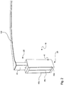
- The present invention is further discussed with respect to the accompanying drawings. The figures show schematically:
- Figure 1
- a view of a terminal according to the present invention,
- Figure 2
- the terminal according to
figure 1 with a mounted heating element, - Figure 3a
- the embodiment of
figure 1 during the hot situation, and - Figure 3b
- the situation of
figure 3a in a further view. - In the
figures 1 to 3b one embodiment of theinventive terminal 10 is shown. According to this embodiment, the terminal 10 comprises a mountingdevice 20 as well as abase device 30. Thebase device 30 is for example fixed on a support plate (not shown) with screws or any other kind of mechanical fixation means. - In
figure 2 it can be seen that aheating element 100 is mounted at the mountingdevice 20. To do so, the mountingdevice 20 comprises anelongated part 22. On the top of thatelongated part 22, thecurved heating element 100 is mounted to the mounting device. One example of auseful heating element 100 is found in "HEATING ELEMENT FOR A PLANAR HEATER OF A MOCVD REACTOR",US-application number 13/568,915, filed on August 7, 2012 device 20 and thebase device 30, asupport device 40 is located. The location of thatsupport device 40 is arranged that such that it is located inside the force track between thebase device 30 and the mountingdevice 20. In other words, any force that is applied by or on theheating element 100 is guided from the mountingdevice 20 along the force track and therefore through thesupport device 40 to thebase plate 30 and for example therefore further to a support plate. - The
support device 40 according to the present embodiment can be a spring. The spring can comprise at least two leaf springs. One embodiment of the present invention has threeleaf springs -
Figures 3a and 3b show one situation during the deflection of thesupport device 40. This happens to be during the heating of theheating element 100. As theinventive terminal 10 is used for a MOCVD Reactor, theheating element 100 is heated up to 1000 to 2200° Celsius. As it can be seen infigure 2 , theheating element 100 is of a relatively large dimension. After and during heating up of that process temperature, theheating element 100 is affected by the thermally induced deformation. In particular, the dimension of theheating element 100 is getting longer and therefore tends to move radially outward. To reduce thermally induced stress inside of theheating element 100, the terminal 10 according to the present invention allows a movement of theheating element 100 relative to thebase device 30. This movement is carried out against thesupport device 40 as it can be seen schematically in thefigures 3a and 3b . - The mounting
device 20 is dislocated as to thebase device 30 by a parallel movement of the mountingdevice 20 relative to thebase device 30. To do so, thedifferent leaf springs leaf springs figure 2 , that single main spring direction is directed in the radial direction as to the heating element when it is mounted at the mounting device and oriented position. Therefore, the radial deformation direction is decoupled from further deformation directions of theheating element 100 as well as of the terminal 10. The decoupling is in particular carried out such that a deformation in a radial direction results in less than 10% of a deformation in any other deformation direction, in particular in the tangential out or the axial direction of theheating element 100. -
- 10
- Terminal
- 20
- mounting device
- 22
- elongated part
- 30
- base device
- 40
- support device
- 42a
- leaf spring
- 42b
- leaf spring
- 42c
- leaf spring
- 100
- Heating element
Claims (8)
- Terminal (10) for mechanical support of a heating element (100), comprising a base device (30), a mounting device (20), the mounting device (20) adapted to support the heating element (100), and a support device (40) connecting the base device (30) to the mounting device (20), the support device (40) allowing displacement of the heating element (100) along a single main elastic direction, whereas the support device (40) is characterized in that it is a leaf spring which comprises two or more leaves (42a, 42b, 42c) arranged in a substantially parallel orientation.
- Terminal (10) according to claim 1, characterized in that the support device (40) allows displacement of the heating element (100) along a radial axis and less than about 10% displacement of the heating element (100) along a tangential and/or axial axis.
- Terminal (10) according to claim 1 or 2, characterized in that the material of the terminal (10) comprises at least 90 % by weight of a refractory metal.
- Terminal (10) according to claim 3, characterized in that the refractory metal is selected from tungsten, molybdenum, niobium, tantalum, rhenium, and alloys thereof.
- Terminal (10) according to claim 3 or 4, characterized in that the refractory metal is selected from tungsten, an alloy of tungsten, molybdenum, and an alloy of molybdenum.
- Heater comprising at least one heating element (100) and at least two terminals (10) according to any of claims 1 to 5.
- Heater according to claim 6, characterized in that the support device (40) of at least one terminal (10) is pre-tensioned in its stable position.
- Heater according to claim 7, characterized in that the pre-tension of the support device (40) is configured to achieve a reduced spring tension of the support device (40) during the heating use of the heating element (100).
Applications Claiming Priority (2)
| Application Number | Priority Date | Filing Date | Title |
|---|---|---|---|
| US13/568,928 US10136472B2 (en) | 2012-08-07 | 2012-08-07 | Terminal for mechanical support of a heating element |
| PCT/EP2013/002336 WO2014023413A1 (en) | 2012-08-07 | 2013-08-05 | Terminal for mechanical support of a heating element |
Publications (2)
| Publication Number | Publication Date |
|---|---|
| EP2882883A1 EP2882883A1 (en) | 2015-06-17 |
| EP2882883B1 true EP2882883B1 (en) | 2017-10-04 |
Family
ID=49034030
Family Applications (1)
| Application Number | Title | Priority Date | Filing Date |
|---|---|---|---|
| EP13752822.0A Active EP2882883B1 (en) | 2012-08-07 | 2013-08-05 | Terminal for mechanical support of a heating element |
Country Status (8)
| Country | Link |
|---|---|
| US (1) | US10136472B2 (en) |
| EP (1) | EP2882883B1 (en) |
| JP (1) | JP6341912B2 (en) |
| KR (1) | KR102203331B1 (en) |
| CN (1) | CN104769155B (en) |
| SG (1) | SG11201500826VA (en) |
| TW (1) | TWI625765B (en) |
| WO (1) | WO2014023413A1 (en) |
Families Citing this family (5)
| Publication number | Priority date | Publication date | Assignee | Title |
|---|---|---|---|---|
| US9497803B2 (en) * | 2014-02-03 | 2016-11-15 | Plansee Se | Supporting system for a heating element and heating system |
| US9992917B2 (en) | 2014-03-10 | 2018-06-05 | Vulcan GMS | 3-D printing method for producing tungsten-based shielding parts |
| CN106385717B (en) * | 2016-08-30 | 2019-10-25 | 广州文冲船厂有限责任公司 | A kind of heating cable support and its method for supporting |
| JP7517972B2 (en) * | 2020-12-04 | 2024-07-17 | 京セラ株式会社 | Sample holder |
| CN116356292B (en) * | 2021-12-27 | 2025-07-08 | 南昌中微半导体设备有限公司 | Heater assembly and vapor deposition equipment |
Family Cites Families (27)
| Publication number | Priority date | Publication date | Assignee | Title |
|---|---|---|---|---|
| US1759722A (en) * | 1928-05-26 | 1930-05-20 | Watson John Warren | Multiple-leaf spring |
| DE1619999A1 (en) | 1967-04-07 | 1970-03-26 | Siemens Ag | Device for the thermal treatment of disc-shaped bodies for semiconductor purposes |
| JPS605089U (en) | 1983-06-22 | 1985-01-14 | 株式会社フジクラ | Planar heating element support structure |
| US4833039A (en) * | 1985-09-26 | 1989-05-23 | General Electric Company | Hermetic feedthrough in ceramic substrate |
| JPH0745107B2 (en) * | 1989-03-24 | 1995-05-17 | 昭博 斎藤 | Pressurization device for resistance welding |
| US5447570A (en) | 1990-04-23 | 1995-09-05 | Genus, Inc. | Purge gas in wafer coating area selection |
| US5209518A (en) * | 1991-03-11 | 1993-05-11 | Detroit Steel Products Co., Inc. | Dual-stage tapered leaf spring for a trailer |
| US5643649A (en) * | 1995-07-31 | 1997-07-01 | International Business Machines Corporation | Method for improving the flatness of glass disk substrates |
| TW506620U (en) | 1996-03-15 | 2002-10-11 | Asahi Glass Co Ltd | Low pressure CVD apparatus |
| JPH10189227A (en) | 1996-12-27 | 1998-07-21 | Shin Etsu Chem Co Ltd | Heating unit and connection method thereof |
| JP3042448B2 (en) | 1997-06-11 | 2000-05-15 | 日本電気株式会社 | CVD equipment |
| US6118100A (en) | 1997-11-26 | 2000-09-12 | Mattson Technology, Inc. | Susceptor hold-down mechanism |
| US6534751B2 (en) * | 2000-02-28 | 2003-03-18 | Kyocera Corporation | Wafer heating apparatus and ceramic heater, and method for producing the same |
| US7071551B2 (en) | 2000-05-26 | 2006-07-04 | Ibiden Co., Ltd. | Device used to produce or examine semiconductors |
| JP2002203664A (en) | 2000-12-28 | 2002-07-19 | Ibiden Co Ltd | Ceramic heater for semiconductor manufacturing and inspection equipment |
| US6856078B2 (en) | 2001-06-27 | 2005-02-15 | Asm America, Inc. | Lamp filament design |
| US7524532B2 (en) | 2002-04-22 | 2009-04-28 | Aixtron Ag | Process for depositing thin layers on a substrate in a process chamber of adjustable height |
| DE10217806A1 (en) * | 2002-04-22 | 2003-10-30 | Aixtron Ag | Method and device for depositing thin layers on a substrate in a higher adjustable process chamber |
| JP2004119520A (en) | 2002-09-24 | 2004-04-15 | Tokyo Electron Ltd | Substrate processing equipment |
| US6902572B2 (en) * | 2003-04-02 | 2005-06-07 | Scimed Life Systems, Inc. | Anchoring mechanisms for intravascular devices |
| WO2006060134A2 (en) | 2004-11-15 | 2006-06-08 | Cree, Inc. | Restricted radiated heating assembly for high temperature processing |
| KR100584189B1 (en) | 2005-03-16 | 2006-05-29 | 동경 엘렉트론 주식회사 | Substrate mounting mechanism and substrate processing apparatus with substrate heating function |
| JP4951211B2 (en) * | 2005-04-27 | 2012-06-13 | 本田技研工業株式会社 | Backbar support structure for welding |
| KR20110046586A (en) | 2007-01-17 | 2011-05-04 | 도쿄엘렉트론가부시키가이샤 | Table structure, and processing apparatus |
| JP5657948B2 (en) | 2009-09-02 | 2015-01-21 | キヤノンアネルバ株式会社 | Vacuum processing apparatus and substrate transfer method |
| JP5606174B2 (en) | 2010-01-27 | 2014-10-15 | 株式会社日立国際電気 | A substrate processing apparatus, a substrate processing method, a semiconductor device manufacturing method, and a reaction chamber closing method. |
| JP5592706B2 (en) | 2010-06-02 | 2014-09-17 | 助川電気工業株式会社 | Sheath heater lead wire connection terminal |
-
2012
- 2012-08-07 US US13/568,928 patent/US10136472B2/en active Active
-
2013
- 2013-06-14 TW TW102121082A patent/TWI625765B/en active
- 2013-08-05 JP JP2015525775A patent/JP6341912B2/en active Active
- 2013-08-05 KR KR1020157002930A patent/KR102203331B1/en active Active
- 2013-08-05 WO PCT/EP2013/002336 patent/WO2014023413A1/en not_active Ceased
- 2013-08-05 EP EP13752822.0A patent/EP2882883B1/en active Active
- 2013-08-05 CN CN201380041627.5A patent/CN104769155B/en active Active
- 2013-08-05 SG SG11201500826VA patent/SG11201500826VA/en unknown
Non-Patent Citations (1)
| Title |
|---|
| None * |
Also Published As
| Publication number | Publication date |
|---|---|
| SG11201500826VA (en) | 2015-03-30 |
| US20140042147A1 (en) | 2014-02-13 |
| TW201411701A (en) | 2014-03-16 |
| US10136472B2 (en) | 2018-11-20 |
| CN104769155B (en) | 2017-11-21 |
| EP2882883A1 (en) | 2015-06-17 |
| CN104769155A (en) | 2015-07-08 |
| KR20150042783A (en) | 2015-04-21 |
| KR102203331B1 (en) | 2021-01-15 |
| WO2014023413A1 (en) | 2014-02-13 |
| TWI625765B (en) | 2018-06-01 |
| JP2015531962A (en) | 2015-11-05 |
| JP6341912B2 (en) | 2018-06-13 |
Similar Documents
| Publication | Publication Date | Title |
|---|---|---|
| US10136472B2 (en) | Terminal for mechanical support of a heating element | |
| US9551071B2 (en) | Substrate support device | |
| US10458659B2 (en) | Snap spring clip for burner unit mounting | |
| KR102276520B1 (en) | Supporting system for a heating element | |
| US11480365B2 (en) | Retaining body, heating device and method | |
| US9497803B2 (en) | Supporting system for a heating element and heating system | |
| US8565283B2 (en) | Insert and a heater element for electrical furnaces | |
| EP2882884B1 (en) | Heating element for a planar heater of a mocvd reactor | |
| EP2610570A1 (en) | Heating element arrangement for a vacuum heat treating furnace | |
| US20190062036A1 (en) | Vacuum heat insulating container | |
| CN105745744B (en) | The substrate carrier that thermal energy for reduction transmits | |
| US8987641B2 (en) | High performance heater | |
| JP5891953B2 (en) | Support member, heating plate support device, and heating device | |
| WO2008148769A2 (en) | A cooking range | |
| CN116356292B (en) | Heater assembly and vapor deposition equipment | |
| JP6298727B2 (en) | Electric heater and heating apparatus provided with the same | |
| WO2011014493A1 (en) | Thermal strain relief device for high temperature furnace | |
| CN120109046A (en) | Heat treatment device | |
| CN104662197B (en) | Heating assembly for the plane heater of Metalorganic chemical vapor deposition reactor |
Legal Events
| Date | Code | Title | Description |
|---|---|---|---|
| PUAI | Public reference made under article 153(3) epc to a published international application that has entered the european phase |
Free format text: ORIGINAL CODE: 0009012 |
|
| 17P | Request for examination filed |
Effective date: 20150120 |
|
| AK | Designated contracting states |
Kind code of ref document: A1 Designated state(s): AL AT BE BG CH CY CZ DE DK EE ES FI FR GB GR HR HU IE IS IT LI LT LU LV MC MK MT NL NO PL PT RO RS SE SI SK SM TR |
|
| AX | Request for extension of the european patent |
Extension state: BA ME |
|
| DAX | Request for extension of the european patent (deleted) | ||
| GRAP | Despatch of communication of intention to grant a patent |
Free format text: ORIGINAL CODE: EPIDOSNIGR1 |
|
| INTG | Intention to grant announced |
Effective date: 20170314 |
|
| GRAS | Grant fee paid |
Free format text: ORIGINAL CODE: EPIDOSNIGR3 |
|
| GRAA | (expected) grant |
Free format text: ORIGINAL CODE: 0009210 |
|
| AK | Designated contracting states |
Kind code of ref document: B1 Designated state(s): AL AT BE BG CH CY CZ DE DK EE ES FI FR GB GR HR HU IE IS IT LI LT LU LV MC MK MT NL NO PL PT RO RS SE SI SK SM TR |
|
| REG | Reference to a national code |
Ref country code: GB Ref legal event code: FG4D |
|
| REG | Reference to a national code |
Ref country code: CH Ref legal event code: EP |
|
| REG | Reference to a national code |
Ref country code: AT Ref legal event code: REF Ref document number: 934124 Country of ref document: AT Kind code of ref document: T Effective date: 20171015 |
|
| REG | Reference to a national code |
Ref country code: IE Ref legal event code: FG4D |
|
| REG | Reference to a national code |
Ref country code: NL Ref legal event code: FP |
|
| REG | Reference to a national code |
Ref country code: DE Ref legal event code: R096 Ref document number: 602013027509 Country of ref document: DE |
|
| REG | Reference to a national code |
Ref country code: SE Ref legal event code: TRGR |
|
| REG | Reference to a national code |
Ref country code: NL Ref legal event code: PD Owner name: PLANSEE SE; AT Free format text: DETAILS ASSIGNMENT: CHANGE OF OWNER(S), ASSIGNMENT; FORMER OWNER NAME: VEECO INSTRUMENTS INC. Effective date: 20171208 |
|
| REG | Reference to a national code |
Ref country code: LT Ref legal event code: MG4D |
|
| REG | Reference to a national code |
Ref country code: CH Ref legal event code: PUEA Owner name: PLANSEE SE, AT Free format text: FORMER OWNER: VEECO INSTRUMENTS INC., AT Ref country code: CH Ref legal event code: NV Representative=s name: ISLER AND PEDRAZZINI AG, CH |
|
| PG25 | Lapsed in a contracting state [announced via postgrant information from national office to epo] |
Ref country code: NO Free format text: LAPSE BECAUSE OF FAILURE TO SUBMIT A TRANSLATION OF THE DESCRIPTION OR TO PAY THE FEE WITHIN THE PRESCRIBED TIME-LIMIT Effective date: 20180104 Ref country code: LT Free format text: LAPSE BECAUSE OF FAILURE TO SUBMIT A TRANSLATION OF THE DESCRIPTION OR TO PAY THE FEE WITHIN THE PRESCRIBED TIME-LIMIT Effective date: 20171004 Ref country code: ES Free format text: LAPSE BECAUSE OF FAILURE TO SUBMIT A TRANSLATION OF THE DESCRIPTION OR TO PAY THE FEE WITHIN THE PRESCRIBED TIME-LIMIT Effective date: 20171004 |
|
| PG25 | Lapsed in a contracting state [announced via postgrant information from national office to epo] |
Ref country code: IS Free format text: LAPSE BECAUSE OF FAILURE TO SUBMIT A TRANSLATION OF THE DESCRIPTION OR TO PAY THE FEE WITHIN THE PRESCRIBED TIME-LIMIT Effective date: 20180204 Ref country code: GR Free format text: LAPSE BECAUSE OF FAILURE TO SUBMIT A TRANSLATION OF THE DESCRIPTION OR TO PAY THE FEE WITHIN THE PRESCRIBED TIME-LIMIT Effective date: 20180105 Ref country code: HR Free format text: LAPSE BECAUSE OF FAILURE TO SUBMIT A TRANSLATION OF THE DESCRIPTION OR TO PAY THE FEE WITHIN THE PRESCRIBED TIME-LIMIT Effective date: 20171004 Ref country code: LV Free format text: LAPSE BECAUSE OF FAILURE TO SUBMIT A TRANSLATION OF THE DESCRIPTION OR TO PAY THE FEE WITHIN THE PRESCRIBED TIME-LIMIT Effective date: 20171004 Ref country code: RS Free format text: LAPSE BECAUSE OF FAILURE TO SUBMIT A TRANSLATION OF THE DESCRIPTION OR TO PAY THE FEE WITHIN THE PRESCRIBED TIME-LIMIT Effective date: 20171004 Ref country code: BG Free format text: LAPSE BECAUSE OF FAILURE TO SUBMIT A TRANSLATION OF THE DESCRIPTION OR TO PAY THE FEE WITHIN THE PRESCRIBED TIME-LIMIT Effective date: 20180104 |
|
| REG | Reference to a national code |
Ref country code: DE Ref legal event code: R097 Ref document number: 602013027509 Country of ref document: DE |
|
| PG25 | Lapsed in a contracting state [announced via postgrant information from national office to epo] |
Ref country code: CZ Free format text: LAPSE BECAUSE OF FAILURE TO SUBMIT A TRANSLATION OF THE DESCRIPTION OR TO PAY THE FEE WITHIN THE PRESCRIBED TIME-LIMIT Effective date: 20171004 Ref country code: SK Free format text: LAPSE BECAUSE OF FAILURE TO SUBMIT A TRANSLATION OF THE DESCRIPTION OR TO PAY THE FEE WITHIN THE PRESCRIBED TIME-LIMIT Effective date: 20171004 Ref country code: DK Free format text: LAPSE BECAUSE OF FAILURE TO SUBMIT A TRANSLATION OF THE DESCRIPTION OR TO PAY THE FEE WITHIN THE PRESCRIBED TIME-LIMIT Effective date: 20171004 Ref country code: EE Free format text: LAPSE BECAUSE OF FAILURE TO SUBMIT A TRANSLATION OF THE DESCRIPTION OR TO PAY THE FEE WITHIN THE PRESCRIBED TIME-LIMIT Effective date: 20171004 |
|
| PLBE | No opposition filed within time limit |
Free format text: ORIGINAL CODE: 0009261 |
|
| STAA | Information on the status of an ep patent application or granted ep patent |
Free format text: STATUS: NO OPPOSITION FILED WITHIN TIME LIMIT |
|
| REG | Reference to a national code |
Ref country code: FR Ref legal event code: PLFP Year of fee payment: 6 |
|
| PG25 | Lapsed in a contracting state [announced via postgrant information from national office to epo] |
Ref country code: RO Free format text: LAPSE BECAUSE OF FAILURE TO SUBMIT A TRANSLATION OF THE DESCRIPTION OR TO PAY THE FEE WITHIN THE PRESCRIBED TIME-LIMIT Effective date: 20171004 Ref country code: PL Free format text: LAPSE BECAUSE OF FAILURE TO SUBMIT A TRANSLATION OF THE DESCRIPTION OR TO PAY THE FEE WITHIN THE PRESCRIBED TIME-LIMIT Effective date: 20171004 Ref country code: SM Free format text: LAPSE BECAUSE OF FAILURE TO SUBMIT A TRANSLATION OF THE DESCRIPTION OR TO PAY THE FEE WITHIN THE PRESCRIBED TIME-LIMIT Effective date: 20171004 |
|
| 26N | No opposition filed |
Effective date: 20180705 |
|
| PG25 | Lapsed in a contracting state [announced via postgrant information from national office to epo] |
Ref country code: SI Free format text: LAPSE BECAUSE OF FAILURE TO SUBMIT A TRANSLATION OF THE DESCRIPTION OR TO PAY THE FEE WITHIN THE PRESCRIBED TIME-LIMIT Effective date: 20171004 |
|
| PG25 | Lapsed in a contracting state [announced via postgrant information from national office to epo] |
Ref country code: MC Free format text: LAPSE BECAUSE OF FAILURE TO SUBMIT A TRANSLATION OF THE DESCRIPTION OR TO PAY THE FEE WITHIN THE PRESCRIBED TIME-LIMIT Effective date: 20171004 |
|
| PG25 | Lapsed in a contracting state [announced via postgrant information from national office to epo] |
Ref country code: LU Free format text: LAPSE BECAUSE OF NON-PAYMENT OF DUE FEES Effective date: 20180805 |
|
| REG | Reference to a national code |
Ref country code: BE Ref legal event code: MM Effective date: 20180831 |
|
| REG | Reference to a national code |
Ref country code: IE Ref legal event code: MM4A |
|
| REG | Reference to a national code |
Ref country code: AT Ref legal event code: PC Ref document number: 934124 Country of ref document: AT Kind code of ref document: T Owner name: PLANSEE SE, AT Effective date: 20190523 |
|
| PG25 | Lapsed in a contracting state [announced via postgrant information from national office to epo] |
Ref country code: IE Free format text: LAPSE BECAUSE OF NON-PAYMENT OF DUE FEES Effective date: 20180805 |
|
| PG25 | Lapsed in a contracting state [announced via postgrant information from national office to epo] |
Ref country code: BE Free format text: LAPSE BECAUSE OF NON-PAYMENT OF DUE FEES Effective date: 20180831 |
|
| PG25 | Lapsed in a contracting state [announced via postgrant information from national office to epo] |
Ref country code: MT Free format text: LAPSE BECAUSE OF NON-PAYMENT OF DUE FEES Effective date: 20180805 |
|
| PG25 | Lapsed in a contracting state [announced via postgrant information from national office to epo] |
Ref country code: TR Free format text: LAPSE BECAUSE OF FAILURE TO SUBMIT A TRANSLATION OF THE DESCRIPTION OR TO PAY THE FEE WITHIN THE PRESCRIBED TIME-LIMIT Effective date: 20171004 |
|
| PG25 | Lapsed in a contracting state [announced via postgrant information from national office to epo] |
Ref country code: PT Free format text: LAPSE BECAUSE OF FAILURE TO SUBMIT A TRANSLATION OF THE DESCRIPTION OR TO PAY THE FEE WITHIN THE PRESCRIBED TIME-LIMIT Effective date: 20171004 Ref country code: HU Free format text: LAPSE BECAUSE OF FAILURE TO SUBMIT A TRANSLATION OF THE DESCRIPTION OR TO PAY THE FEE WITHIN THE PRESCRIBED TIME-LIMIT; INVALID AB INITIO Effective date: 20130805 |
|
| PG25 | Lapsed in a contracting state [announced via postgrant information from national office to epo] |
Ref country code: CY Free format text: LAPSE BECAUSE OF FAILURE TO SUBMIT A TRANSLATION OF THE DESCRIPTION OR TO PAY THE FEE WITHIN THE PRESCRIBED TIME-LIMIT Effective date: 20171004 Ref country code: MK Free format text: LAPSE BECAUSE OF NON-PAYMENT OF DUE FEES Effective date: 20171004 |
|
| PG25 | Lapsed in a contracting state [announced via postgrant information from national office to epo] |
Ref country code: AL Free format text: LAPSE BECAUSE OF FAILURE TO SUBMIT A TRANSLATION OF THE DESCRIPTION OR TO PAY THE FEE WITHIN THE PRESCRIBED TIME-LIMIT Effective date: 20171004 |
|
| REG | Reference to a national code |
Ref country code: AT Ref legal event code: UEP Ref document number: 934124 Country of ref document: AT Kind code of ref document: T Effective date: 20171004 |
|
| PGFP | Annual fee paid to national office [announced via postgrant information from national office to epo] |
Ref country code: NL Payment date: 20250821 Year of fee payment: 13 |
|
| PGFP | Annual fee paid to national office [announced via postgrant information from national office to epo] |
Ref country code: FI Payment date: 20250822 Year of fee payment: 13 |
|
| PGFP | Annual fee paid to national office [announced via postgrant information from national office to epo] |
Ref country code: DE Payment date: 20250820 Year of fee payment: 13 |
|
| PGFP | Annual fee paid to national office [announced via postgrant information from national office to epo] |
Ref country code: IT Payment date: 20250825 Year of fee payment: 13 |
|
| PGFP | Annual fee paid to national office [announced via postgrant information from national office to epo] |
Ref country code: GB Payment date: 20250820 Year of fee payment: 13 |
|
| PGFP | Annual fee paid to national office [announced via postgrant information from national office to epo] |
Ref country code: FR Payment date: 20250829 Year of fee payment: 13 Ref country code: AT Payment date: 20250821 Year of fee payment: 13 |
|
| PGFP | Annual fee paid to national office [announced via postgrant information from national office to epo] |
Ref country code: CH Payment date: 20250901 Year of fee payment: 13 Ref country code: SE Payment date: 20250820 Year of fee payment: 13 |