EP2882050A2 - Multiple spark route for lightning protection - Google Patents
Multiple spark route for lightning protection Download PDFInfo
- Publication number
- EP2882050A2 EP2882050A2 EP14401100.4A EP14401100A EP2882050A2 EP 2882050 A2 EP2882050 A2 EP 2882050A2 EP 14401100 A EP14401100 A EP 14401100A EP 2882050 A2 EP2882050 A2 EP 2882050A2
- Authority
- EP
- European Patent Office
- Prior art keywords
- spark gap
- contact plate
- housing
- electrode plates
- connection
- Prior art date
- Legal status (The legal status is an assumption and is not a legal conclusion. Google has not performed a legal analysis and makes no representation as to the accuracy of the status listed.)
- Granted
Links
- 239000004020 conductor Substances 0.000 claims abstract description 53
- 239000011810 insulating material Substances 0.000 claims description 36
- 230000007935 neutral effect Effects 0.000 claims description 11
- 238000007599 discharging Methods 0.000 claims description 8
- 230000002093 peripheral effect Effects 0.000 claims description 4
- 238000009434 installation Methods 0.000 description 7
- 230000005405 multipole Effects 0.000 description 3
- 229920001343 polytetrafluoroethylene Polymers 0.000 description 2
- 239000004810 polytetrafluoroethylene Substances 0.000 description 2
- OKTJSMMVPCPJKN-UHFFFAOYSA-N Carbon Chemical compound [C] OKTJSMMVPCPJKN-UHFFFAOYSA-N 0.000 description 1
- 238000010276 construction Methods 0.000 description 1
- 238000007796 conventional method Methods 0.000 description 1
- 238000005516 engineering process Methods 0.000 description 1
- 229910002804 graphite Inorganic materials 0.000 description 1
- 239000010439 graphite Substances 0.000 description 1
- 238000009413 insulation Methods 0.000 description 1
- 239000008141 laxative Substances 0.000 description 1
- 230000002475 laxative effect Effects 0.000 description 1
- 239000002184 metal Substances 0.000 description 1
- 239000004033 plastic Substances 0.000 description 1
- -1 polytetrafluoroethylene Polymers 0.000 description 1
Images


Classifications
-
- H—ELECTRICITY
- H01—ELECTRIC ELEMENTS
- H01T—SPARK GAPS; OVERVOLTAGE ARRESTERS USING SPARK GAPS; SPARKING PLUGS; CORONA DEVICES; GENERATING IONS TO BE INTRODUCED INTO NON-ENCLOSED GASES
- H01T4/00—Overvoltage arresters using spark gaps
- H01T4/06—Mounting arrangements for a plurality of overvoltage arresters
-
- H—ELECTRICITY
- H01—ELECTRIC ELEMENTS
- H01T—SPARK GAPS; OVERVOLTAGE ARRESTERS USING SPARK GAPS; SPARKING PLUGS; CORONA DEVICES; GENERATING IONS TO BE INTRODUCED INTO NON-ENCLOSED GASES
- H01T4/00—Overvoltage arresters using spark gaps
- H01T4/16—Overvoltage arresters using spark gaps having a plurality of gaps arranged in series
Definitions
- the invention relates to a multiple spark gap for lightning protection, consisting of between terminal contact plates and contact plates with connection means for electrical conductors arranged spark gaps.
- the electrode plates are preferably provided in the form of circular graphite disks.
- the present invention seeks to provide a multi-pole spark gap, which has a compact relatively small design, allows for simplified assembly and additionally brings handling advantages.
- an insulating material housing which has a plurality of mutually insulated chambers, which open to a housing side open and in which each of the housing bottom adjacent to a terminal contact plate and on a contacted with this spark gap is used, of the connection contact plates each connecting means for each electrical Conductor are discharged through the housing to the outside of the insulating material, that the open side of the housing is covered by a first contact plate of electrically conductive material, which is contacted with the spark gaps on its side facing away from the housing bottom and the terminal contact plates and is connected to the insulating housing by connecting means, wherein the first contact plate comprises connection means for electrical conductors.
- the invention provides a multipolar spark gap in a single device. This has a reduced space requirement compared to the conventional modular design result. Furthermore, the assembly effort is reduced and also simplifies handling, because only a single device must be installed, but not several devices must be arranged side by side.
- a plurality of mutually insulated chambers are provided in an insulating material, which are each equipped with a spark gap.
- Each spark gap has a connection contact plate, to each of which one pole of the multipolar network can be connected.
- This device combination is completed by the fact that on the open side of the housing, a first contact plate made of electrically conductive material is applied, which in a suitable manner with the Insulating housing is connected.
- This contact plate is contacted on the one hand with the spark gaps with which they z. B. is in direct contact, on the other hand, this first contact plate has connection means for a corresponding electrical conductor, for example, the neutral conductor.
- a first connection means discharging from a first connection contact plate for connection to a first current-carrying phase (L1)
- a second connection means discharging from a second connection contact plate for connection to a second current-carrying phase (L2)
- a third from a third connection contact plate laxative connection means for connection to a third current-carrying phase (L3) is determined and the connection means of the first contact plate are intended for connection to a neutral conductor.
- the first contact plate is approximately L-shaped, wherein the first leg covers the open side of the housing and the second leg has a side surface of the Covered insulating material, and that a further spark gap between the second leg and a parallel held second contact plate made of electrically conductive material contacted with two contact plates is arranged, wherein the second contact plate has a connection means for connecting a PE conductor.
- the first contact plate is intended to be contacted on the one hand with the spark gaps
- the second leg of the first contact plate is intended to receive a terminal end of another spark gap, wherein the other end of the spark gap is connected to a second contact plate.
- the two contact plates can be connected to one another by insulated screw connections or the like.
- the first contact plate is intended to be at neutral potential, so be connected to neutral, while the second contact plate is to be connected to a PE conductor, so that the total device combination not only forms a three-pin connection option for three phase conductors, but an additional connection option for the PE Ladder.
- connection means for connection to the current-carrying phases (L1, L2, L3) projecting rectified to each other via the housing bottom from one side of the insulating material and the connection means of the first contact plate and, if a second contact plate is arranged, the connection means of the second contact plate rectified to each other and projecting in opposite directions to the connection means of the current-carrying phases via the housing mouth.
- connection means for the connection with the current-carrying phases can be equipped, for example with contact terminals or the like, so that corresponding conductors can be connected in a simple manner.
- connection means for the connection of the neutral conductor or the PE conductor may be formed by terminals, in which such conductors are insertable and contactable by means of the terminal and can be clamped.
- the arrangement on opposite sides of the overall combination is advantageous for the placement of the corresponding cables or conductors.
- each spark gap consists of stacked single spark gaps in the form of ring-shaped or disk-shaped electrode plates, between which respective annular insulating disks are arranged.
- all or some electrode plates are contacted with electrical / electronic control elements for influencing the distribution of stress over the stack arrangement.
- the Isolierstoffgeophuse for each stack of single spark gaps has a unilaterally open rectangular chamber which is bounded by side walls and a bottom wall, and that each chamber has in corner areas or near the corner regions over the height of the chamber formed support ribs on which the electrode plates and the insulating disks or only the insulating disks are supported.
- electrode plates and insulating discs can be used in the chambers in which the electrode plates lie behind with its outer circumference behind the outer periphery of the insulating material.
- a support of only the Isolierstoffin takes place on the support ribs. Centering and support of the electrode plates can be realized in other ways.
- the electrode plates terminate flush with the insulating material disks on the circumference.
- the electrode plates are opposite to the Insulating disks are located on the circumference.
- the electrode plates terminate flush with the insulating material when the electrode plates terminate flush with the insulating material is preferably provided that the electrode plates have a peripheral edge formed with a chamfer and the insulating material having a maximum outside diameter of the electrode plates in the dimension matched outer diameter.
- a mandrel protrudes centrally aligned to the chamber, to which the provided with a suitable perforation electrode plates and the insulating material are threaded.
- the electrode plates provided with a central perforation are aligned and held on the mandrel centric to the chamber.
- the Isolierstoffawan are disposed between the electrode plates and are not centered and held by the mandrel, but by the support ribs located in the corner areas.
- an attachment of the first contact plate to the housing can be effected in that a fastening screw is guided centrally through the mandrel or screwed into the mandrel.
- each chamber the ground immediately adjacent a terminal contact plate is arranged, which engages with a radially projecting arm an opening or a wall slot of a side wall of the chamber, the outside of the chamber has connection means for a conductor.
- the chamber bottom has a recess, is inserted in the terminal contact plate fitting.
- At least one of the support ribs in the amount of the inserted electrode plates has slots which open to the electrode plates and outwardly open and that in at least some Slots controls are used, which contact the respective electrode plate edge and connected via a connecting means to a neutral conductor leading component of the multiple spark gap.
- This arrangement makes it possible to supply corresponding controls in a simple manner and to contact the electrode plates, wherein the control elements can each be held in a desired position via a common contact spring and correspondingly contacted with the first contact plate, so that they are switched to the corresponding potential.
- the controls are resiliently held against the electrode plates on investment.
- the complete assembly is surrounded by a multi-part housing made of insulating material, which has access openings for electrical connection lines and for actuating conductor terminals.
- the complete structural unit is surrounded by a housing, preferably with a lower part and an upper part made of insulating material.
- a housing preferably with a lower part and an upper part made of insulating material.
- this unit is to handle and appropriate place, for example, in a Integral modular housing.
- To the corresponding connection points can be supplied via the access openings in each case a corresponding conductor and by means of the conductor terminals, the applied conductors can be fixed.
- the open side of the housing insulating housing 1 is connected by a first contact plate 9 made of electrically conductive material z. B. covered from metal.
- This first contact plate 9 is contacted in assembly target position with the spark gaps 7 inserted into the insulating 1 on its side facing away from the housing bottom 5 and the terminal contact plates 6, so applied to this. Furthermore, the first contact plate 9 in the assembly target position with the insulating material. 1 connected by connecting means, such as screws.
- the first contact plate 9 also has connection means 13 for at least one electrical conductor.
- a first connection means 8 discharging from a first connection contact plate 6 serves for connection to a first current-carrying phase, for example L1.
- a second connection means 8 discharging from a second connection contact plate 6 serves for connection to a second current-carrying phase, for example L2.
- a third connection means 8 discharging from the third connection contact plate 6 serves for connection to a third current-carrying phase, for example L3.
- the connection means 13 of the first contact plate 9 serve for connection to a neutral conductor.
- the first contact plate 9 is formed as an L-shaped part, wherein the first leg covers the open side of the insulating housing 1 and the second leg covers a side surface of the insulating housing 1 and rests against this.
- a further spark gap 10 is arranged between the second leg of the first contact plate 9 and a second contact plate 11, held in parallel thereto, made of electrically conductive material, wherein the spark gap 10 is contacted with both contact plates.
- the second contact plate 11 with a Connection means 12 equipped, to which a PE conductor is to be connected. Due to the arrangement of the other spark gap 10, the total combination is not increased in their overall length or width, but only in the overall height.
- connection means 8 for connection to the current-carrying phases L1, L2, L3, aligned rectified to each other and protrude beyond the housing bottom 5 of the insulating material 1 to the outside.
- the connection means 13 of the first contact plate 9 and the connection means 12 of the second contact plate 11 are in turn rectified to each other and arranged opposite to the connection means 8 for the current-carrying phases.
- the connection means 12, 13 protrude beyond the housing mouth and in particular over the second leg of the first contact plate 9 to the outside.
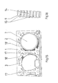
- each spark gap 7 and 10 is formed from stacked arranged single spark gaps in the form of annular or disc-shaped electrode plates, as for example in FIG. 3 and FIG. 16 is illustrated. Between Electrode plates 14 are each annular insulating material 15 z. B. arranged from PTFE. Furthermore, at least the electrode plates 14 of the spark gap 7 are contacted with electronic control elements 16, which serve for influencing the stress distribution over the respective stack arrangement.
- Each of these chambers 2, 3, 4 has in the corner regions and near the corner regions over the height of the chamber formed support ribs 17, 18, in which the electrode plates 14 in the arrangement, as shown in FIG. 16 is shown, and support the insulating discs 15.
- the insulating material 15 are based on the support ribs 17, 18 on the outer circumference side.
- each electrode plate 14 has a narrow cylindrical outer peripheral region, to which the tapered bevel 19 connects.
- the insulating discs 15 have the same outer diameter as the cylindrical portions of the electrode plates 14.
- the respective chamber 2, 3, 4 of the insulating material housing 1 is formed with a central mandrel 20, on each of which provided with a matching hole 21 electrode plates 14 are fittingly plugged.
- the insulating material 15 are formed only as narrow rings, which are arranged only in the edge region between the electrode plates 14 and in this embodiment, as in FIG. 3 is shown, the outer circumference of the support ribs 17, 18 are supported, so that so that the whole stack is held in the correct position oriented.
- the connection contact plate 9 can be placed and fixed by means of screws, wherein the screws can be guided, for example, through the mandrel 20.
- FIG. 15 is a corresponding Stack arrangement of electrode plates 14 and insulating washers 15 analogous to the representation in FIG. 16 inserted into the corresponding chambers 2, 3, 4.
- the first contact plate 9 can be placed and fixed by means of screws, which are guided by perforations in the corner region of the insulating material and in the corner regions between the chambers 2, 3, 4.
- each chamber 2, 3, 4 the bottom 5 immediately adjacent a terminal contact plate 6 is arranged, which with a radially projecting, cranked arm an opening or a wall slot 22 of a side wall of the respective chamber. 2 , 3, 4 passes through, which on the outside from the chamber has excellent connection means 8 for the corresponding contacts or conductors.
- the chamber bottom 5 has a depression or recess 23 into which the respective terminal contact plate 6 can be inserted in a suitable manner.
- both support ribs 18 have mutually offset in the amount of the respectively inserted electrode plates 14 slots 24 which, as in particular FIG. 17 is illustrated open to the outside of the respective chamber 2, 3, 4 open.
- the controls 16 of used outside so that they contact the respective electrode plate 14.
- the controls 16 are resiliently held against the peripheral edge of the electrode plates 14 on investment.
- FIG. 1 it can be seen, the complete assembly of a two-part housing 26, 27 is surrounded, which consists of insulating material and which has access openings for the electrical connection lines and the operation of provided conductor terminals 28.
- the entire unit is shielded arranged in the housing, provided that it is mounted around the unit.
- the housing can be placed and mounted in a conventional manner on a rail in an installation cabinet or the like.
- each of the conductor terminals 28 has a clamping region for clamping a corresponding connection conductor and set screws for actuating the respective terminal, which are accessible in the final assembly position through corresponding housing openings of the housing 27.
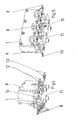
- FIG. 1 is a corresponding exploded view of the items of the overall device shown.
- the device is shown in the assembly, wherein the housing 27 is partially broken, so that the inner components are partially visible.
- FIG. 3 an embodiment of a stacked arrangement of a spark gap with electrode plates 14 and insulating washers 15 is shown.
- FIG. 4 is shown a partial assembly of the items, which is particularly clear that, as well FIG. 5 shows, the further spark gap 10 is mounted spatially under the insulating material on the one leg of the first contact plate 9.
- FIG. 6 is an embodiment of an insulating housing in an oblique view from above.
- the FIG. 7 shows a detail of FIG. 6 , partially broken.
- FIG. 15 a variant of an insulating housing is shown.
- the associated stack arrangement of electrode plates 14 and insulating washers 15 is in FIG. 16 shown as a detail enlargement.
- FIG. 8 is an insulating housing 1 with an inserted stack of insulating 15 and electrode plates 14th shown. The other two places are not yet filled.
- FIG. 9 the arrangement provided with the first contact plate 9 is shown with insulating housing 1, wherein only the end face with the first contact plate 9 can be seen.
- FIG. 10 is the one leg of the first contact plate 9 can be seen and seen the insulating material 1 from below.
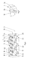
- FIG. 11 an exploded view of another embodiment is shown, similar to FIG. 1 , in which FIG. 12 show more details in another view.
- FIGS. 13 and 14 show a partial assembly of the insulating material 1 with the first contact plate 9 and other elements in different directions.
- FIG. 15 shows this embodiment of the insulating material 1 with inserted into a chamber 2 stack of electrode plates 14 and insulating discs 15, wherein a detail of this embodiment in FIG. 16 is shown.
- FIGS. 17 and 18 finally shows as a detail the contacting of the control elements 16 with the electrode plates 14 in the installed position.
- the exemplary embodiments show a multi-pole spark gap according to the invention with three lightning current dissipation elements for the three phases L1, L2, L3 and a PE-N arrester, in each case including the neutral conductor connection.
Abstract
Die Erfindung betrifft eine Mehrfachfunkenstrecke für den Blitzschutz, bestehend aus zwischen Anschlusskontaktplatten und Kontaktplatten mit Anschlussmitteln für elektrische Leiter angeordneten Funkenstrecken, wobei ein Isolierstoffgehäuse (1) angeordnet ist, welches mehrere voneinander isolierte Kammern (2, 3, 4) aufweist, eine Anschlusskontaktplatte (6) und darauf eine mit dieser kontaktierte Funkenstrecke (7) eingesetzt ist, wobei von den Anschlusskontaktplatten (6) jeweils Anschlussmittel (8) für jeweils elektrische Leiter durch die Gehäusewandung zur Außenseite des Isolierstoffgehäuses (1) abgeführt sind, wobei die offene Gehäuseseite durch eine erste Kontaktplatte (9) aus elektrisch leitfähigem Werkstoff abgedeckt ist, die mit den Funkenstrecken (7) auf ihrer den Anschlusskontaktplatten (6) abgewandten Seite kontaktiert ist und mit dem Isolierstoffgehäuse (1) durch Verbindungsmittel verbunden ist, wobei die erste Kontaktplatte (9) Anschlussmittel (13) für elektrische Leiter aufweist.The invention relates to a multiple spark gap for lightning protection, consisting of between terminal contact plates and contact plates with connection means for electrical conductors arranged spark gaps, an insulating housing (1) is arranged, which has a plurality of mutually insulated chambers (2, 3, 4), a terminal contact plate (6 ) and thereupon a contact with this contacted spark gap (7) is inserted, wherein from the terminal contact plates (6) each connection means (8) are discharged for each electrical conductor through the housing to the outside of the insulating housing (1), wherein the open side of the housing by a first Contact plate (9) made of electrically conductive material is covered, which is contacted with the spark gaps (7) on its terminal contact plates (6) facing away from and connected to the insulating housing (1) by connecting means, wherein the first contact plate (9) connecting means ( 13) for electrical Head has.
Description
Die Erfindung betrifft eine Mehrfachfunkenstrecke für den Blitzschutz, bestehend aus zwischen Anschlusskontaktplatten und Kontaktplatten mit Anschlussmitteln für elektrische Leiter angeordneten Funkenstrecken.The invention relates to a multiple spark gap for lightning protection, consisting of between terminal contact plates and contact plates with connection means for electrical conductors arranged spark gaps.
Aus der
Zum Stand der Technik wird ferner auf die
Im Stand der Technik ist es bisher üblich und notwendig, dass jeweils für jede Phase des Stromnetzes eine solche Mehrfachfunkenstrecke angeordnet wird, und ebenso zwischen PE und Nullleiter eine entsprechende Funkenstrecke vorzusehen. Dies bedeutet einen nicht unerheblichen Montageaufwand für beispielsweise die Dreifachanordnung bei einem Netz mit drei Phasenableitern oder sogar die Vierfachanordnung, wenn zusätzlich eine Absicherung zwischen PE-N erfolgen soll. Aus dieser herkömmlichen Anordnung resultiert nicht nur ein zusätzlicher Montageaufwand, sondern diese Anordnung benötigt auch einen entsprechenden Einbauraum. Ein solcher Einbauraum ist regelmäßig in Installationsschränken oder dergleichen beschränkt, in denen solche Funkenstrecken vorzusehen sind.In the prior art, it has been customary and necessary that in each case for each phase of the power network such a multiple spark gap is arranged, and also provide between PE and neutral a corresponding spark gap. This means a considerable installation effort for example, the triple arrangement in a network with three phase arresters or even the quadruple arrangement, if in addition a hedge between PE-N should take place. From this conventional arrangement results not only an additional installation effort, but this arrangement also requires a corresponding installation space. Such installation space is regularly limited in installation cabinets or the like, in which such spark gaps are provided.
Ausgehend von diesem Stand der Technik liegt der Erfindung die Aufgabe zugrunde, eine mehrpolige Funkenstrecke zu schaffen, die eine kompakte relativ kleine Bauform hat, eine vereinfachte Montage ermöglicht und zusätzlich Handhabungsvorteile mit sich bringt.Based on this prior art, the present invention seeks to provide a multi-pole spark gap, which has a compact relatively small design, allows for simplified assembly and additionally brings handling advantages.
Zur Lösung dieser Aufgabe schlägt die Erfindung vor, dass ein Isolierstoffgehäuse angeordnet ist, welches mehrere voneinander isolierte Kammern aufweist, die zu einer Gehäuseseite hin offen ausmünden und in welche jeweils dem Gehäuseboden benachbart eine Anschlusskontaktplatte und darauf eine mit dieser kontaktierte Funkenstrecke eingesetzt ist, wobei von den Anschlusskontaktplatten jeweils Anschlussmittel für jeweils elektrische Leiter durch die Gehäusewandung zur Außenseite des Isolierstoffgehäuses abgeführt sind, dass die offene Gehäuseseite durch eine erste Kontaktplatte aus elektrisch leitfähigem Werkstoff abgedeckt ist, die mit den Funkenstrecken auf ihrer dem Gehäuseboden und den Anschlusskontaktplatten abgewandten Seite kontaktiert ist und mit dem Isolierstoffgehäuse durch Verbindungsmittel verbunden ist, wobei die erste Kontaktplatte Anschlussmittel für elektrische Leiter aufweist.To solve this problem, the invention proposes that an insulating material housing is arranged, which has a plurality of mutually insulated chambers, which open to a housing side open and in which each of the housing bottom adjacent to a terminal contact plate and on a contacted with this spark gap is used, of the connection contact plates each connecting means for each electrical Conductor are discharged through the housing to the outside of the insulating material, that the open side of the housing is covered by a first contact plate of electrically conductive material, which is contacted with the spark gaps on its side facing away from the housing bottom and the terminal contact plates and is connected to the insulating housing by connecting means, wherein the first contact plate comprises connection means for electrical conductors.
Die Erfindung stellt eine mehrpolige Funkenstrecke in einem einzigen Gerät zur Verfügung. Dies hat einen verminderten Raumbedarf gegenüber der herkömmlichen Modulbauweise zur Folge. Des Weiteren wird der Montageaufwand vermindert und auch die Handhabung vereinfacht, weil nur noch ein einziges Gerät installiert werden muss, nicht aber mehrere Geräte nebeneinander angeordnet werden müssen.The invention provides a multipolar spark gap in a single device. This has a reduced space requirement compared to the conventional modular design result. Furthermore, the assembly effort is reduced and also simplifies handling, because only a single device must be installed, but not several devices must be arranged side by side.
Gemäß der Erfindung sind in einem Isolierstoffgehäuse mehrere voneinander isolierte Kammern vorgesehen, die jeweils mit einer Funkenstrecke bestückt werden. Jede Funkenstrecke hat eine Anschlusskontaktplatte, an die jeweils ein Pol des mehrpoligen Netzes anschließbar ist. Diese Gerätekombination wird dadurch komplettiert, dass auf die offene Gehäuseseite eine erste Kontaktplatte aus elektrisch leitfähigem Werkstoff aufgebracht wird, die in geeigneter Weise mit dem Isolierstoffgehäuse verbunden wird. Diese Kontaktplatte ist einerseits mit den Funkenstrecken kontaktiert, mit denen sie z. B. in direkten Kontakt steht, wobei andererseits diese erste Kontaktplatte Anschlussmittel für einen entsprechenden elektrischen Leiter aufweist, beispielsweise den Nullleiter.According to the invention a plurality of mutually insulated chambers are provided in an insulating material, which are each equipped with a spark gap. Each spark gap has a connection contact plate, to each of which one pole of the multipolar network can be connected. This device combination is completed by the fact that on the open side of the housing, a first contact plate made of electrically conductive material is applied, which in a suitable manner with the Insulating housing is connected. This contact plate is contacted on the one hand with the spark gaps with which they z. B. is in direct contact, on the other hand, this first contact plate has connection means for a corresponding electrical conductor, for example, the neutral conductor.
Bevorzugt ist dabei vorgesehen, dass ein erstes von einer ersten Anschlusskontaktplatte abführendes Anschlussmittel zur Verbindung mit einer ersten stromführenden Phase (L1), ein zweites von einer zweiten Anschlusskontaktplatte abführendes Anschlussmittel zur Verbindung mit einer zweiten stromführenden Phase (L2), ein drittes von einer dritten Anschlusskontaktplatte abführendes Anschlussmittel zur Verbindung mit einer dritten stromführenden Phase (L3) bestimmt ist und die Anschlussmittel der ersten Kontaktplatte zur Verbindung mit einem Null-Leiter bestimmt sind.It is preferably provided that a first connection means discharging from a first connection contact plate for connection to a first current-carrying phase (L1), a second connection means discharging from a second connection contact plate for connection to a second current-carrying phase (L2), a third from a third connection contact plate laxative connection means for connection to a third current-carrying phase (L3) is determined and the connection means of the first contact plate are intended for connection to a neutral conductor.
Auf diese Weise wird eine mehrpolige sehr kompakte Baueinheit der Mehrfachfunkenstrecke zur Verfügung gestellt.In this way, a multipolar very compact unit of the multiple spark gap is provided.
Um unter Beibehalt der kompakten Bauform noch eine weitere Funktion in diese Mehrfachfunkenstrecke einzubringen, ist vorgesehen, dass die erste Kontaktplatte etwa L-förmig ausgebildet ist, wobei derer erster Schenkel die offene Gehäuseseite abdeckt und deren zweiter Schenkel eine Seitenfläche des Isolierstoffgehäuses überdeckt, und dass eine weitere Funkenstrecke zwischen dem zweiten Schenkel und einer dazu parallelen isoliert gehaltenen zweiten Kontaktplatte aus elektrisch leitfähigem Werkstoff mit beiden Kontaktplatten kontaktiert angeordnet ist, wobei die zweite Kontaktplatte ein Anschlussmittel zum Anschluss einen PE-Leiter aufweist.In order to introduce still another function in this multiple spark gap while maintaining the compact design, it is provided that the first contact plate is approximately L-shaped, wherein the first leg covers the open side of the housing and the second leg has a side surface of the Covered insulating material, and that a further spark gap between the second leg and a parallel held second contact plate made of electrically conductive material contacted with two contact plates is arranged, wherein the second contact plate has a connection means for connecting a PE conductor.
Gemäß dieser Anordnung ist die erste Kontaktplatte dazu bestimmt, einerseits mit den Funkenstrecken kontaktiert zu werden, wobei andererseits der zweite Schenkel der ersten Kontaktplatte dazu bestimmt ist, ein Anschlussende einer weiteren Funkenstrecke aufzunehmen, wobei das andere Ende der Funkenstrecke an eine zweite Kontaktplatte angeschlossen wird. Die beiden Kontaktplatten können durch isolierte Verschraubungen oder dergleichen miteinander verbunden sein. Die erste Kontaktplatte soll bestimmungsgemäß auf Nullleiter-Potential liegen, also an Nullleiter angeschlossen sein, während die zweite Kontaktplatte an einen PE-Leiter anzuschließen ist, sodass die Gesamtgerätekombination nicht nur eine dreipolige Anschlussmöglichkeit für drei Phasenleiter bildet, sondern eine zusätzliche Anschlussmöglichkeit für den PE-Leiter. Insgesamt ist somit in die Mehrfachfunkenstrecke eine Vierfachanordnung von Funkenstrecken integriert, was die Gesamtbauform und das gesamte Bauvolumen gegenüber der herkömmlichen Technik weiter vermindert. Dies insbesondere dadurch, dass die Funkenstrecke für den N-PE-Anschluss nicht neben den weiteren Funkenstrecken angeordnet ist, sondern untergebaut ist, sodass die Baulänge der Gesamtkombination gegenüber der herkömmlichen Verbindungs- und Anschlusstechnik vermindert wird.According to this arrangement, the first contact plate is intended to be contacted on the one hand with the spark gaps, on the other hand, the second leg of the first contact plate is intended to receive a terminal end of another spark gap, wherein the other end of the spark gap is connected to a second contact plate. The two contact plates can be connected to one another by insulated screw connections or the like. The first contact plate is intended to be at neutral potential, so be connected to neutral, while the second contact plate is to be connected to a PE conductor, so that the total device combination not only forms a three-pin connection option for three phase conductors, but an additional connection option for the PE Ladder. Overall, thus a quadruple arrangement of spark gaps is integrated into the multiple spark gap, which further reduces the overall design and the overall construction volume compared to the conventional technique. This in particular by the fact that the Spark gap for the N-PE connection is not located next to the other spark gaps, but is built under, so that the overall length of the overall combination compared to the conventional connection and connection technology is reduced.
Zur Verbesserung der Handhabung ist zudem vorgesehen, dass die Anschlussmittel zur Verbindung mit den stromführenden Phasen (L1, L2, L3) gleichgerichtet zueinander über den Gehäuseboden aus einer Seite des Isolierstoffgehäuses vorragen und die Anschlussmittel der ersten Kontaktplatte und, sofern eine zweite Kontaktplatte angeordnet ist, die Anschlussmittel der zweiten Kontaktplatte gleichgerichtet zueinander und entgegengerichtet zu den Anschlussmitteln der stromführenden Phasen über die Gehäusemündung vorragen.To improve the handling is also provided that the connection means for connection to the current-carrying phases (L1, L2, L3) projecting rectified to each other via the housing bottom from one side of the insulating material and the connection means of the first contact plate and, if a second contact plate is arranged, the connection means of the second contact plate rectified to each other and projecting in opposite directions to the connection means of the current-carrying phases via the housing mouth.
Die Anschlussmittel für die Verbindung mit den stromführenden Phasen können beispielsweise mit Kontaktklemmen oder dergleichen bestückt werden, sodass entsprechende Leiter in einfacher Weise angeschlossen werden können. Auch die Anschlussmittel für den Anschluss des Nullleiters bzw. des PE-Leiters, können durch Klemmen gebildet sein, in die solche Leiter einführbar und mittels der Klemme kontaktierbar und klemmbar sind. Die Anordnung an entgegengerichteten Seiten der Gesamtkombination ist für das Auflegen der entsprechenden Kabel bzw. Leiter, vorteilhaft. Insbesondere ist bevorzugt vorgesehen, dass jede Funkenstrecke aus stapelartig angeordneten Einzelfunkenstrecken in Form von ring- oder scheibenförmigen Elektrodenplatten, zwischen denen jeweils ringförmige Isolierstoffscheiben angeordnet sind, besteht.The connection means for the connection with the current-carrying phases can be equipped, for example with contact terminals or the like, so that corresponding conductors can be connected in a simple manner. Also, the connection means for the connection of the neutral conductor or the PE conductor may be formed by terminals, in which such conductors are insertable and contactable by means of the terminal and can be clamped. The arrangement on opposite sides of the overall combination is advantageous for the placement of the corresponding cables or conductors. In particular, it is preferably provided that each spark gap consists of stacked single spark gaps in the form of ring-shaped or disk-shaped electrode plates, between which respective annular insulating disks are arranged.
Bezüglich der weiteren Ausgestaltung solcher Mehrfachfunkenstrecken wird auf die
Zudem kann auch vorgesehen sein, dass alle oder einige Elektrodenplatten mit elektrischen/elektronischen Steuerelementen zur Beeinflussung der Spannungsverteilung über der Stapelanordnung kontaktiert sind.In addition, it can also be provided that all or some electrode plates are contacted with electrical / electronic control elements for influencing the distribution of stress over the stack arrangement.
Eine besonders bevorzugte Ausgestaltung wird darin gesehen, dass das Isolierstoffgehäuse für jeden Stapel von Einzelfunkenstrecken eine einseitig offene rechteckige Kammer aufweist, die von Seitenwänden und einer Bodenwand umgrenzt ist, und dass jede Kammer in Eckbereichen oder nahe der Eckbereiche über die Höhe der Kammer ausgebildete Stützrippen aufweist, an denen sich die Elektrodenplatten und die Isolierstoffscheiben oder nur die Isolierstoffscheiben abstützen.A particularly preferred embodiment is seen in that the Isolierstoffgehäuse for each stack of single spark gaps has a unilaterally open rectangular chamber which is bounded by side walls and a bottom wall, and that each chamber has in corner areas or near the corner regions over the height of the chamber formed support ribs on which the electrode plates and the insulating disks or only the insulating disks are supported.
Durch diese Anordnung und Ausgestaltung wird folgendes erreicht. Sofern in die jeweilige Kammer Elektrodenplatten und Isolierstoffscheiben mit gleichem Außendurchmesser eingesetzt werden, können sich diese an den vorzugsweise etwa diametral gegenüberliegend angeordneten Stützrippen abstützen und zentrieren, sodass eine zentrische Anordnung und eine ausreichend sichere Lage gewährleistet ist. Diese Anordnung ist vor allem dann bevorzugt, wenn die erste Kontaktplatte mit dem Isolierstoffgehäuse jeweils in den Eckbereichen der Einzelkammern mittels Schrauben befestigt wird.By this arrangement and configuration, the following is achieved. If in the respective Chamber electrode plates and insulating discs are used with the same outer diameter, these can be supported on the preferably approximately diametrically opposed support ribs and center, so that a centric arrangement and a sufficiently secure position is guaranteed. This arrangement is especially preferred when the first contact plate with the insulating material is fastened in each case in the corner regions of the individual chambers by means of screws.
Sofern, wie dies die Erfindung auch vorsieht, eine andere Befestigung erfolgen soll, so können auch Elektrodenplatten und Isolierstoffscheiben in die Kammern eingesetzt werden, bei denen die Elektrodenplatten mit ihrem Außenumfang hinter dem Außenumfang der Isolierstoffscheiben zurückliegen. In diesem Falle erfolgt eine Abstützung lediglich der Isolierstoffscheiben an den Stützrippen. Eine Zentrierung und Stützung der Elektrodenplatten kann in anderer Weise realisiert werden.If, as the invention also envisages, another attachment is to be made, so also electrode plates and insulating discs can be used in the chambers in which the electrode plates lie behind with its outer circumference behind the outer periphery of the insulating material. In this case, a support of only the Isolierstoffscheiben takes place on the support ribs. Centering and support of the electrode plates can be realized in other ways.
In einer unter Umständen bevorzugten Ausgestaltung ist vorgesehen, dass die Elektrodenplatten mit den Isolierstoffscheiben umfangsseitig bündig abschließen.In a possibly preferred embodiment, it is provided that the electrode plates terminate flush with the insulating material disks on the circumference.
In einer alternativen bevorzugten Ausgestaltung kann vorgesehen sein, dass die Elektrodenplatten gegenüber den Isolierstoffscheiben umfangsseitig zurückliegen.In an alternative preferred embodiment it can be provided that the electrode plates are opposite to the Insulating disks are located on the circumference.
Insbesondere dann, wenn die Elektrodenplatten mit den Isolierstoffscheiben umfangsseitig bündig abschließen ist bevorzugt vorgesehen, dass die Elektrodenplatten einen mit einer Fase ausgebildeten umlaufenden Rand aufweisen und die Isolierstoffscheiben einen dem maximalen Außendurchmesser der Elektrodenplatten in der Abmessung angepassten Außendurchmesser aufweisen.In particular, when the electrode plates terminate flush with the insulating material is preferably provided that the electrode plates have a peripheral edge formed with a chamfer and the insulating material having a maximum outside diameter of the electrode plates in the dimension matched outer diameter.
Durch diese Ausgestaltung wird die Kriechstrecke zwischen den durch die Isolierstoffscheiben getrennten Elektrodenplatten vergrößert, sodass einem Spannungsüberschlag in diesem Bereich entgegengewirkt wird. Dies wird in gleicher Weise dann erreicht, wenn die Isolierstoffscheiben gegenüber den Elektrodenplatten ausreichend vorragen.By this configuration, the creepage distance between the separated by the insulating material electrode plates is increased, so that a voltage flashover is counteracted in this area. This is achieved in the same way if the Isolierstoffscheiben protrude sufficiently against the electrode plates.
Insbesondere bei dieser Ausgestaltung ist bevorzugt vorgesehen, dass vom Kammerboden ein Dorn zentrisch zur Kammer ausgerichtet abragt, auf den die mit einer passenden Lochung versehenen Elektrodenplatten sowie die Isolierstoffscheiben aufgefädelt sind.In particular, in this embodiment, it is preferably provided that from the bottom of the chamber a mandrel protrudes centrally aligned to the chamber, to which the provided with a suitable perforation electrode plates and the insulating material are threaded.
Gemäß dieser konstruktiven Lösung werden die mit einer Mittellochung versehenen Elektrodenplatten auf dem Dorn zentrisch zur Kammer ausgerichtet und gehalten. Die Isolierstoffscheiben sind zwischen den Elektrodenplatten angeordnet und werden nicht durch den Dorn, sondern durch die in den Eckbereichen befindlichen Stützrippen zentriert und gehalten.According to this constructive solution, the electrode plates provided with a central perforation are aligned and held on the mandrel centric to the chamber. The Isolierstoffscheiben are disposed between the electrode plates and are not centered and held by the mandrel, but by the support ribs located in the corner areas.
In diesem Falle kann auch eine Befestigung der ersten Kontaktplatte an dem Gehäuse dadurch erfolgen, dass eine Befestigungsschraube zentrisch durch den Dorn geführt oder in den Dorn geschraubt wird. Solche Lösungen sind unter anderem auch in der
Eine bevorzugte Weiterbildung wird zudem darin gesehen, dass in jeder Kammer dem Boden unmittelbar benachbart eine Anschlusskontaktplatte angeordnet ist, die mit einem radial abragenden Arm eine Öffnung oder einen Wandungsschlitz einer Seitenwandung der Kammer durchgreift, der außenliegend der Kammer Anschlussmittel für einen Leiter aufweist.A preferred development is also seen in that in each chamber the ground immediately adjacent a terminal contact plate is arranged, which engages with a radially projecting arm an opening or a wall slot of a side wall of the chamber, the outside of the chamber has connection means for a conductor.
Hierbei ist bevorzugt vorgesehen, dass der Kammerboden eine Ausnehmung aufweist, in die Anschlusskontaktplatte passend eingelegt ist.Here, it is preferably provided that the chamber bottom has a recess, is inserted in the terminal contact plate fitting.
Eine besonders bevorzugte Weiterbildung wird darin gesehen, dass mindestens eine der Stützrippen in Höhe der eingelegten Elektrodenplatten Schlitze aufweist, die zu den Elektrodenplatten und nach außen offen ausmünden und dass in mindestens einige Schlitze Steuerelemente eingesetzt sind, die die jeweilige Elektrodenplatte randseitig kontaktieren und über ein Verbindungsmittel an einen Nullleiter-Potential führenden Bestandteil der Mehrfachfunkenstrecke angeschlossen sind.A particularly preferred development is seen in that at least one of the support ribs in the amount of the inserted electrode plates has slots which open to the electrode plates and outwardly open and that in at least some Slots controls are used, which contact the respective electrode plate edge and connected via a connecting means to a neutral conductor leading component of the multiple spark gap.
Diese Anordnung ermöglicht es in einfacher Weise entsprechende Steuerelemente zuzuführen und mit den Elektrodenplatten zu kontaktieren, wobei die Steuerelemente jeweils über eine gemeinsame Kontaktfeder in Solllage gehalten werden können und entsprechend mit der ersten Kontaktplatte kontaktiert werden können, sodass sie auf das entsprechende Potential geschaltet sind.This arrangement makes it possible to supply corresponding controls in a simple manner and to contact the electrode plates, wherein the control elements can each be held in a desired position via a common contact spring and correspondingly contacted with the first contact plate, so that they are switched to the corresponding potential.
Bevorzugt ist hierbei vorgesehen, dass die Steuerelemente federnd gegen die Elektrodenplatten auf Anlage gehalten sind.Preferably, it is provided that the controls are resiliently held against the electrode plates on investment.
Des Weiteren ist bevorzugt, dass die komplette Baueinheit von einem mehrteiligen Gehäuse aus Isolierstoff umgeben ist, welches Zugangsöffnungen für elektrische Anschlussleitungen und zur Betätigung von Leiterklemmen aufweist.Furthermore, it is preferred that the complete assembly is surrounded by a multi-part housing made of insulating material, which has access openings for electrical connection lines and for actuating conductor terminals.
Erfindungsgemäß ist die komplette Baueinheit durch ein Gehäuse vorzugsweise mit einem Unterteil und einem Oberteil aus Isolierstoff umgeben. Zur Montage ist lediglich diese Baueinheit zu handhaben und an entsprechender Stelle beispielsweise in ein Reiheneinbaugehäuse zu integrieren. An die entsprechenden Anschlussstellen kann über die Zugangsöffnungen jeweils ein entsprechender Leiter zugeführt werden und mittels der Leiterklemmen können die aufgelegten Leiter fixiert werden.According to the invention, the complete structural unit is surrounded by a housing, preferably with a lower part and an upper part made of insulating material. For assembly, only this unit is to handle and appropriate place, for example, in a Integral modular housing. To the corresponding connection points can be supplied via the access openings in each case a corresponding conductor and by means of the conductor terminals, the applied conductors can be fixed.
Ausführungsbeispiele der Erfindung sind in der Zeichnung dargestellt und im Folgenden näher beschrieben.Embodiments of the invention are illustrated in the drawings and described in more detail below.
Es zeigt:
Figur 1- eine erste Ausführungsform in Explosionsdarstellung;
Figur 2- eine Ausführungsform im Zusammenbau, teilweise aufgebrochen;
Figur 3- eine Einzelheit in Ansicht gesehen;
Figur 4- eine weitere Einzelheit in Ansicht Von schräg unten gesehen;
Figur 5- desgleichen in eine um 90° um die Hochachse gedrehten Lage;
- Figur 6
- eine Einzelheit in Draufsicht gesehen;
Figur 7- die Einzelheit VII der
Figur 6 in vergrößerter Ansicht gezeigt; Figur 8- eine weitere Einzelheit in Draufsicht gesehen;
Figur 9- die Einzelheit mit weiteren Teilen kombiniert in Ansicht;
Figur 10- desgleichen in Rückansicht;
Figur 11- eine Ausführungsform in Explosionsdarstellung;
Figur 12- die Ausführungsform in Explosionsansicht in anderer Blickrichtung gesehen;
Figur 13- eine Einzelheit von schräg unten gesehen;
Figur 14- die Einzelheit von oben gesehen;
Figur 15- eine weitere Einzelheit in Draufsicht gesehen;
Figur 16- eine Einzelheit in Teilansicht gesehen;
Figur 17- eine weitere Einzelheit in Teilansicht;
Figur 18- eine Einzelheit in Draufsicht gesehen.
- FIG. 1
- a first embodiment in exploded view;
- FIG. 2
- an embodiment in the assembly, partially broken away;
- FIG. 3
- a detail seen in view;
- FIG. 4
- another detail in view Seen obliquely from below;
- FIG. 5
- likewise in a position rotated by 90 ° about the vertical axis;
- FIG. 6
- a detail seen in plan view;
- FIG. 7
- the detail VII of
FIG. 6 shown in enlarged view; - FIG. 8
- another detail in Seen from above;
- FIG. 9
- the detail with further parts combined in view;
- FIG. 10
- likewise in rear view;
- FIG. 11
- an embodiment in exploded view;
- FIG. 12
- the embodiment seen in an exploded view in another direction;
- FIG. 13
- a detail viewed from below;
- FIG. 14
- the detail seen from above;
- FIG. 15
- another detail seen in plan view;
- FIG. 16
- a detail seen in partial view;
- FIG. 17
- another detail in partial view;
- FIG. 18
- a detail seen in plan view.
In den Ausführungsbeispielen ist eine mehrpolige Mehrfachfunkenstrecke für den Blitzschutz gezeigt, die in einem einzigen Gerät zusammengefasst ist. Wesentliche Bestandteile dieser Ausgestaltung sind folgende.In the embodiments, a multi-pole multiple spark gap for the lightning protection is shown in a single device is summarized. Essential components of this embodiment are the following.
Es ist ein Isolierstoffgehäuse 1 z. B. aus Kunststoff vorgesehen, welches mehrere voneinander isolierte Kammern 2, 3, 4 aufweist. Diese Kammern 2, 3, 4 sind, wie insbesondere aus
Die offene Gehäuseseite des Isolierstoffgehäuses 1 ist durch eine erste Kontaktplatte 9 aus elektrisch leitfähigem Werkstoff z. B. aus Metall abgedeckt. Diese erste Kontaktplatte 9 ist in Montagesolllage mit den in das Isolierstoffgehäuse 1 eingesetzten Funkenstrecken 7 auf ihrer dem Gehäuseboden 5 und den Anschlusskontaktplatten 6 abgewandten Seite kontaktiert, also an diese angelegt. Des Weiteren ist die erste Kontaktplatte 9 in der Montagesolllage mit dem Isolierstoffgehäuse 1 durch Verbindungsmittel, beispielsweise Schrauben, verbunden. Die erste Kontaktplatte 9 weist zudem Anschlussmittel 13 für mindestens einen elektrischen Leiter auf.The open side of the
Ein erstes von einer ersten Anschlusskontaktplatte 6 abführendes Anschlussmittel 8 dient zur Verbindung mit einer ersten stromführenden Phase, beispielsweise L1.A first connection means 8 discharging from a first connection contact plate 6 serves for connection to a first current-carrying phase, for example L1.
Ein zweites von einer zweiten Anschlusskontaktplatte 6 abführendes Anschlussmittel 8 dient zur Verbindung mit einer zweiten stromführenden Phase, beispielsweise L2.A second connection means 8 discharging from a second connection contact plate 6 serves for connection to a second current-carrying phase, for example L2.
Ein drittes von der dritten Anschlusskontaktplatte 6 abführendes Anschlussmittel 8 dient zur Verbindung mit einer dritten stromführenden Phase, beispielsweise L3. Die Anschlussmittel 13 der ersten Kontaktplatte 9 dienen zur Verbindung mit einem Nullleiter.A third connection means 8 discharging from the third connection contact plate 6 serves for connection to a third current-carrying phase, for example L3. The connection means 13 of the
Wie aus den Figuren gut ersichtlich, ist die erste Kontaktplatte 9 als L-förmiges Teil ausgebildet, wobei deren erster Schenkel die offene Seite des Isolierstoffgehäuses 1 abdeckt und deren zweiter Schenkel eine Seitenfläche des Isolierstoffgehäuses 1 überdeckt und an dieser anliegt. Eine weitere Funkenstrecke 10 ist zwischen dem zweiten Schenkel der ersten Kontaktplatte 9 und einer dazu parallel isoliert gehaltenen zweiten Kontaktplatte 11 aus elektrisch leitfähigem Werkstoff angeordnet, wobei die Funkenstrecke 10 mit beiden Kontaktplatten kontaktiert ist. Des Weiteren ist die zweite Kontaktplatte 11 mit einem Anschlussmittel 12 ausgestattet, an welches ein PE-Leiter anzuschließen ist. Durch die Anordnung der weiteren Funkenstrecke 10 wird die Gesamtkombination nicht in ihrer Baulänge oder Baubreite vergrößert, sondern nur in der Bauhöhe.As can be clearly seen from the figures, the
Wie insbesondere aus
Auf diese Weise sind einfach zugängliche Anschlussmöglichkeiten für den Anschluss der elektrischen Leiter zur Verfügung gestellt.In this way, easily accessible connection options for connecting the electrical conductors are provided.
Bei den dargestellten Ausführungsbeispielen ist jede Funkenstrecke 7 bzw. 10 aus stapelartig angeordneten Einzelfunkenstrecken in Form von ringförmigen oder scheibenförmigen Elektrodenplatten gebildet, wie dies beispielsweise in
Wie beispielsweise aus
Bei der Ausführungsform, wie sie beispielsweise in
Die Isolierstoffscheiben 15 weisen den gleichen Außendurchmesser auf, wie die zylindrischen Bereiche der Elektrodenplatten 14.The insulating
Bei der Ausführungsform, wie sie in
Bei der Anordnung, wie sie in
Bei der Ausführungsform, die in den Zeichnungen dargestellt ist, ist in jeder Kammer 2, 3, 4 dem Boden 5 unmittelbar benachbart eine Anschlusskontaktplatte 6 angeordnet, die mit einem radial abragenden, gekröpften Arm eine Öffnung oder einen Wandungsschlitz 22 einer Seitenwandung der jeweiligen Kammer 2, 3, 4 durchgreift, wobei dieser außenseitig aus der Kammer hervorragend die Anschlussmittel 8 für die entsprechenden Kontakte oder Leiter aufweist. Zudem weist der Kammerboden 5 eine Vertiefung oder Ausnehmung 23 auf, in die die jeweilige Anschlusskontaktplatte 6 passend einlegbar ist.In the embodiment shown in the drawings, in each
Mindestens eine der Stützrippen 18, vorzugsweise, wie im Ausführungsbeispielbild gezeigt, beide Stützrippen 18 weisen wechselweise versetzt in Höhe der jeweils eingelegten Elektrodenplatten 14 Schlitze 24 auf, die, wie insbesondere in
Wie insbesondere in
Die Leiterklemmen 28, die beispielsweise in
In
In
In
In
Die Ausführungsbeispiele zeigen eine erfindungsgemäße mehrpolige Funkenstrecke mit drei Blitzstromableitungselementen für die drei Phasen L1, L2, L3 sowie einen PE-N-Ableiter jeweils samt Nullleiteranschluss. Dadurch, dass diese Elemente in einem einzigen Gerät vereinigt sind, wird eine kompakte Gesamtbauform erreicht, die wenig Raumbedarf hat und hinsichtlich der Montage äußerst einfach zu handhaben ist.The exemplary embodiments show a multi-pole spark gap according to the invention with three lightning current dissipation elements for the three phases L1, L2, L3 and a PE-N arrester, in each case including the neutral conductor connection. By combining these elements in a single device are achieved, a compact overall design is achieved, which has little space and is extremely easy to handle in terms of installation.
Die Erfindung ist nicht auf die Ausführungsbeispiele beschränkt, sondern im Rahmen der Offenbarung vielfach variabel.The invention is not limited to the embodiments, but in the context of the disclosure often variable.
Alle in der Beschreibung und/oder Zeichnung offenbarten Einzel- und Kombinationsmerkmale werden als erfindungswesentlich angesehen.All disclosed in the description and / or drawing single and combination features are considered essential to the invention.
- 11
- IsolierstoffgehäuseInsulated
- 22
- Kammerchamber
- 33
- Kammerchamber
- 44
- Kammerchamber
- 55
- Bodenground
- 66
- AnschlusskontaktplatteConnection contact plate
- 77
- Funkenstreckeradio link
- 88th
- Anschlussmittelconnection means
- 99
- erste Kontaktplattefirst contact plate
- 1010
- weitere Funkenstreckefurther spark gap
- 1111
- zweite Kontaktplattesecond contact plate
- 1212
- Anschlussmittel an 11Connection means at 11
- 1313
- Anschlussmittel an 9Connection means at 9
- 1414
- Elektrodenplattenelectrode plates
- 1515
- IsolierstoffscheibenIsolierstoffscheiben
- 1616
- Steuerelementecontrols
- 1717
- Stützrippensupport ribs
- 1818
- Stützrippensupport ribs
- 1919
- Fasechamfer
- 2020
- Dornmandrel
- 2121
- Lochungperforation
- 2222
- Schlitzslot
- 2323
- Ausnehmungrecess
- 2424
- Schlitzeslots
- 2525
- Anschlussleiterconnecting conductors
- 25'25 '
- Mittelleitercenter conductor
- 2626
- Gehäusecasing
- 2727
- Gehäusecasing
- 2828
- LeiterklammerHead brace
Claims (16)
dass die offene Gehäuseseite durch eine erste Kontaktplatte (9) aus elektrisch leitfähigem Werkstoff abgedeckt ist, die mit den Funkenstrecken (7) auf ihrer dem Gehäuseboden (5) und den Anschlusskontaktplatten (6) abgewandten Seite kontaktiert ist und mit dem Isolierstoffgehäuse (1) durch Verbindungsmittel verbunden ist, wobei die erste Kontaktplatte (9) Anschlussmittel (13) für elektrische Leiter aufweist.Multiple spark gap for lightning protection, consisting of between terminal contact plates and contact plates with connection means for electrical conductors arranged spark gaps, characterized in that an insulating material (1) is arranged, which has a plurality of mutually insulated chambers (2, 3, 4), which towards a housing side open out and in which in each case the housing bottom (5) adjacent to a terminal contact plate (6) and thereon a contacted with this spark gap (7) is inserted, of the terminal contact plates (6) respectively connecting means (8) for each electrical conductor through the housing to Outside of the insulating material (1) are discharged,
in that the open housing side is covered by a first contact plate (9) of electrically conductive material, which is contacted with the spark gaps (7) on its side remote from the housing bottom (5) and the terminal contact plates (6) and with the insulating material housing (1) Connecting means is connected, wherein the first contact plate (9) has connection means (13) for electrical conductors.
Priority Applications (1)
| Application Number | Priority Date | Filing Date | Title |
|---|---|---|---|
| SI201430989T SI2882050T1 (en) | 2013-12-06 | 2014-10-29 | Multiple spark route for lightning protection |
Applications Claiming Priority (1)
| Application Number | Priority Date | Filing Date | Title |
|---|---|---|---|
| DE102013113614.1A DE102013113614A1 (en) | 2013-12-06 | 2013-12-06 | Multiple spark gap for lightning protection |
Publications (3)
| Publication Number | Publication Date |
|---|---|
| EP2882050A2 true EP2882050A2 (en) | 2015-06-10 |
| EP2882050A3 EP2882050A3 (en) | 2015-06-17 |
| EP2882050B1 EP2882050B1 (en) | 2018-09-12 |
Family
ID=51870965
Family Applications (1)
| Application Number | Title | Priority Date | Filing Date |
|---|---|---|---|
| EP14401100.4A Active EP2882050B1 (en) | 2013-12-06 | 2014-10-29 | Multiple spark route for lightning protection |
Country Status (5)
| Country | Link |
|---|---|
| EP (1) | EP2882050B1 (en) |
| CN (1) | CN104701742A (en) |
| DE (1) | DE102013113614A1 (en) |
| HK (1) | HK1209910A1 (en) |
| SI (1) | SI2882050T1 (en) |
Families Citing this family (6)
| Publication number | Priority date | Publication date | Assignee | Title |
|---|---|---|---|---|
| CN107240859B (en) * | 2017-06-09 | 2022-04-29 | 武汉水院电气有限责任公司 | Flat plate gap lightning arrester based on short arc potential drop and near-cathode effect superposition |
| CN108199360A (en) * | 2018-01-30 | 2018-06-22 | 四川中光防雷科技股份有限公司 | A kind of pcb board carries multilayer gap-type surge protector |
| DE102018118904B3 (en) | 2018-08-03 | 2019-10-17 | Phoenix Contact Gmbh & Co. Kg | Arrangement of stacked spark gaps and device for holding together and contacting stacked spark gaps |
| DE102018118906B3 (en) * | 2018-08-03 | 2019-10-17 | Phoenix Contact Gmbh & Co. Kg | Surge protection device |
| DE102018118898B3 (en) | 2018-08-03 | 2019-10-24 | Phoenix Contact Gmbh & Co. Kg | Retaining arrangement and arrangement of at least two staple bursts |
| DE102018131537B4 (en) * | 2018-12-10 | 2022-02-03 | Phoenix Contact Gmbh & Co. Kg | Spark gap arrangement for a multi-stacked spark gap |
Citations (3)
| Publication number | Priority date | Publication date | Assignee | Title |
|---|---|---|---|---|
| WO2012052388A1 (en) | 2010-10-22 | 2012-04-26 | Dehn + Söhne Gmbh + Co. Kg | Spark gap having a plurality of series-connected individual spark gaps, which are located in a stack arrangement |
| DE202013102647U1 (en) | 2013-06-19 | 2013-06-26 | Obo Bettermann Gmbh & Co. Kg | Multiple spark gap |
| DE102013102647A1 (en) | 2013-03-14 | 2014-09-18 | Fele Gmbh & Co. Kg | Connecting bushing for a housing of an electrical component, in particular of a rechargeable battery, and method for mounting a connection feedthrough |
Family Cites Families (5)
| Publication number | Priority date | Publication date | Assignee | Title |
|---|---|---|---|---|
| US4658325A (en) * | 1985-04-22 | 1987-04-14 | Northern Telecom Limited | Apparatus for providing positive protection for station protectors for telephone systems |
| DE19742302A1 (en) * | 1997-09-25 | 1999-04-08 | Bettermann Obo Gmbh & Co Kg | Spark gap capable of carrying lightning current |
| EP1075064B1 (en) * | 1999-07-09 | 2007-04-25 | Leutron GmbH | Lightning- and overvoltage protection device |
| DE102006028959A1 (en) * | 2006-06-23 | 2008-01-31 | Dehn + Söhne Gmbh + Co. Kg | Plug-in surge arrester with one or more overvoltage protection elements |
| CN201312120Y (en) * | 2008-10-28 | 2009-09-16 | 四川铭士电子科技有限责任公司 | Switch-type surge protector |
-
2013
- 2013-12-06 DE DE102013113614.1A patent/DE102013113614A1/en not_active Withdrawn
-
2014
- 2014-10-29 EP EP14401100.4A patent/EP2882050B1/en active Active
- 2014-10-29 SI SI201430989T patent/SI2882050T1/en unknown
- 2014-12-05 CN CN201410731244.7A patent/CN104701742A/en active Pending
-
2015
- 2015-10-20 HK HK15110284.7A patent/HK1209910A1/en unknown
Patent Citations (3)
| Publication number | Priority date | Publication date | Assignee | Title |
|---|---|---|---|---|
| WO2012052388A1 (en) | 2010-10-22 | 2012-04-26 | Dehn + Söhne Gmbh + Co. Kg | Spark gap having a plurality of series-connected individual spark gaps, which are located in a stack arrangement |
| DE102013102647A1 (en) | 2013-03-14 | 2014-09-18 | Fele Gmbh & Co. Kg | Connecting bushing for a housing of an electrical component, in particular of a rechargeable battery, and method for mounting a connection feedthrough |
| DE202013102647U1 (en) | 2013-06-19 | 2013-06-26 | Obo Bettermann Gmbh & Co. Kg | Multiple spark gap |
Also Published As
| Publication number | Publication date |
|---|---|
| EP2882050B1 (en) | 2018-09-12 |
| DE102013113614A1 (en) | 2015-06-11 |
| HK1209910A1 (en) | 2016-04-08 |
| CN104701742A (en) | 2015-06-10 |
| EP2882050A3 (en) | 2015-06-17 |
| SI2882050T1 (en) | 2019-01-31 |
Similar Documents
| Publication | Publication Date | Title |
|---|---|---|
| EP2882050B1 (en) | Multiple spark route for lightning protection | |
| EP2018646B1 (en) | Switching device, in particular fused interrupters | |
| EP2816683B1 (en) | Multiple spark path | |
| DE102018118906B3 (en) | Surge protection device | |
| DE102018118904B3 (en) | Arrangement of stacked spark gaps and device for holding together and contacting stacked spark gaps | |
| EP3180817B1 (en) | Connection terminal for a continuous electrical conductor | |
| DE19856939A1 (en) | Circuit arrangement for protecting electrical installations against overvoltage events | |
| EP2690314A1 (en) | Spindle drive | |
| DE102008031200A1 (en) | Surge protection device for single or multi-core signal circuit, has base part fastened to mounting rail, and two plugging parts, each comprising two connecting terminals for respective electrical conductors | |
| EP3144942A1 (en) | Surge arrester | |
| EP1387454B1 (en) | Apparatus with a plug-in contact for connection to a fixed busbar | |
| DE202014101167U1 (en) | Device for dissipating overvoltages | |
| EP2940819A1 (en) | Cable end fitting | |
| DE4022310C2 (en) | Holding structure for an electrical component in a gas-insulated, encapsulated high-voltage device | |
| DE1246060B (en) | High frequency switch | |
| DE102016207292B4 (en) | Electrical protection device and transformer with such | |
| DE202014003281U1 (en) | Kit for cable terminations for connecting a switchgear to a high voltage cable | |
| EP3164919B1 (en) | Cable termination for connecting a switchgear assembly to a high-voltage cable | |
| DE3908532C2 (en) | ||
| DE102020204620B4 (en) | cable connection | |
| EP3276647B1 (en) | Grounding unit for a switching system | |
| DE102011080003A1 (en) | Safety circuit with current conducting screw | |
| DE3129061A1 (en) | Electrical installation apparatus | |
| DE102010033374B4 (en) | Device for the electrical connection of a power module with terminal surface elements | |
| DE1665626B1 (en) | ELECTRIC CONNECTOR |
Legal Events
| Date | Code | Title | Description |
|---|---|---|---|
| PUAL | Search report despatched |
Free format text: ORIGINAL CODE: 0009013 |
|
| PUAI | Public reference made under article 153(3) epc to a published international application that has entered the european phase |
Free format text: ORIGINAL CODE: 0009012 |
|
| 17P | Request for examination filed |
Effective date: 20141029 |
|
| AK | Designated contracting states |
Kind code of ref document: A2 Designated state(s): AL AT BE BG CH CY CZ DE DK EE ES FI FR GB GR HR HU IE IS IT LI LT LU LV MC MK MT NL NO PL PT RO RS SE SI SK SM TR |
|
| AX | Request for extension of the european patent |
Extension state: BA ME |
|
| AK | Designated contracting states |
Kind code of ref document: A3 Designated state(s): AL AT BE BG CH CY CZ DE DK EE ES FI FR GB GR HR HU IE IS IT LI LT LU LV MC MK MT NL NO PL PT RO RS SE SI SK SM TR |
|
| AX | Request for extension of the european patent |
Extension state: BA ME |
|
| RIC1 | Information provided on ipc code assigned before grant |
Ipc: H01T 4/06 20060101AFI20150512BHEP Ipc: H01T 4/16 20060101ALI20150512BHEP |
|
| RIN1 | Information on inventor provided before grant (corrected) |
Inventor name: BREITHAUPT, WOLFGANG Inventor name: SCHURWANZ, JUERGEN Inventor name: HOFFMANN, MARCEL |
|
| R17P | Request for examination filed (corrected) |
Effective date: 20151112 |
|
| RBV | Designated contracting states (corrected) |
Designated state(s): AL AT BE BG CH CY CZ DE DK EE ES FI FR GB GR HR HU IE IS IT LI LT LU LV MC MK MT NL NO PL PT RO RS SE SI SK SM TR |
|
| GRAP | Despatch of communication of intention to grant a patent |
Free format text: ORIGINAL CODE: EPIDOSNIGR1 |
|
| INTG | Intention to grant announced |
Effective date: 20180619 |
|
| GRAS | Grant fee paid |
Free format text: ORIGINAL CODE: EPIDOSNIGR3 |
|
| GRAA | (expected) grant |
Free format text: ORIGINAL CODE: 0009210 |
|
| RAP1 | Party data changed (applicant data changed or rights of an application transferred) |
Owner name: OBO BETTERMANN PRODUKTION DEUTSCHLAND GMBH & CO.KG |
|
| AK | Designated contracting states |
Kind code of ref document: B1 Designated state(s): AL AT BE BG CH CY CZ DE DK EE ES FI FR GB GR HR HU IE IS IT LI LT LU LV MC MK MT NL NO PL PT RO RS SE SI SK SM TR |
|
| REG | Reference to a national code |
Ref country code: GB Ref legal event code: FG4D Free format text: NOT ENGLISH |
|
| REG | Reference to a national code |
Ref country code: CH Ref legal event code: EP |
|
| REG | Reference to a national code |
Ref country code: IE Ref legal event code: FG4D Free format text: LANGUAGE OF EP DOCUMENT: GERMAN |
|
| REG | Reference to a national code |
Ref country code: DE Ref legal event code: R096 Ref document number: 502014009441 Country of ref document: DE |
|
| REG | Reference to a national code |
Ref country code: AT Ref legal event code: REF Ref document number: 1041702 Country of ref document: AT Kind code of ref document: T Effective date: 20181015 |
|
| REG | Reference to a national code |
Ref country code: FR Ref legal event code: PLFP Year of fee payment: 5 |
|
| REG | Reference to a national code |
Ref country code: NL Ref legal event code: MP Effective date: 20180912 |
|
| REG | Reference to a national code |
Ref country code: LT Ref legal event code: MG4D |
|
| PG25 | Lapsed in a contracting state [announced via postgrant information from national office to epo] |
Ref country code: SE Free format text: LAPSE BECAUSE OF FAILURE TO SUBMIT A TRANSLATION OF THE DESCRIPTION OR TO PAY THE FEE WITHIN THE PRESCRIBED TIME-LIMIT Effective date: 20180912 Ref country code: BG Free format text: LAPSE BECAUSE OF FAILURE TO SUBMIT A TRANSLATION OF THE DESCRIPTION OR TO PAY THE FEE WITHIN THE PRESCRIBED TIME-LIMIT Effective date: 20181212 Ref country code: GR Free format text: LAPSE BECAUSE OF FAILURE TO SUBMIT A TRANSLATION OF THE DESCRIPTION OR TO PAY THE FEE WITHIN THE PRESCRIBED TIME-LIMIT Effective date: 20181213 Ref country code: LT Free format text: LAPSE BECAUSE OF FAILURE TO SUBMIT A TRANSLATION OF THE DESCRIPTION OR TO PAY THE FEE WITHIN THE PRESCRIBED TIME-LIMIT Effective date: 20180912 Ref country code: NO Free format text: LAPSE BECAUSE OF FAILURE TO SUBMIT A TRANSLATION OF THE DESCRIPTION OR TO PAY THE FEE WITHIN THE PRESCRIBED TIME-LIMIT Effective date: 20181212 Ref country code: RS Free format text: LAPSE BECAUSE OF FAILURE TO SUBMIT A TRANSLATION OF THE DESCRIPTION OR TO PAY THE FEE WITHIN THE PRESCRIBED TIME-LIMIT Effective date: 20180912 Ref country code: FI Free format text: LAPSE BECAUSE OF FAILURE TO SUBMIT A TRANSLATION OF THE DESCRIPTION OR TO PAY THE FEE WITHIN THE PRESCRIBED TIME-LIMIT Effective date: 20180912 |
|
| PG25 | Lapsed in a contracting state [announced via postgrant information from national office to epo] |
Ref country code: LV Free format text: LAPSE BECAUSE OF FAILURE TO SUBMIT A TRANSLATION OF THE DESCRIPTION OR TO PAY THE FEE WITHIN THE PRESCRIBED TIME-LIMIT Effective date: 20180912 Ref country code: AL Free format text: LAPSE BECAUSE OF FAILURE TO SUBMIT A TRANSLATION OF THE DESCRIPTION OR TO PAY THE FEE WITHIN THE PRESCRIBED TIME-LIMIT Effective date: 20180912 Ref country code: HR Free format text: LAPSE BECAUSE OF FAILURE TO SUBMIT A TRANSLATION OF THE DESCRIPTION OR TO PAY THE FEE WITHIN THE PRESCRIBED TIME-LIMIT Effective date: 20180912 |
|
| PG25 | Lapsed in a contracting state [announced via postgrant information from national office to epo] |
Ref country code: EE Free format text: LAPSE BECAUSE OF FAILURE TO SUBMIT A TRANSLATION OF THE DESCRIPTION OR TO PAY THE FEE WITHIN THE PRESCRIBED TIME-LIMIT Effective date: 20180912 Ref country code: NL Free format text: LAPSE BECAUSE OF FAILURE TO SUBMIT A TRANSLATION OF THE DESCRIPTION OR TO PAY THE FEE WITHIN THE PRESCRIBED TIME-LIMIT Effective date: 20180912 Ref country code: RO Free format text: LAPSE BECAUSE OF FAILURE TO SUBMIT A TRANSLATION OF THE DESCRIPTION OR TO PAY THE FEE WITHIN THE PRESCRIBED TIME-LIMIT Effective date: 20180912 Ref country code: ES Free format text: LAPSE BECAUSE OF FAILURE TO SUBMIT A TRANSLATION OF THE DESCRIPTION OR TO PAY THE FEE WITHIN THE PRESCRIBED TIME-LIMIT Effective date: 20180912 Ref country code: IS Free format text: LAPSE BECAUSE OF FAILURE TO SUBMIT A TRANSLATION OF THE DESCRIPTION OR TO PAY THE FEE WITHIN THE PRESCRIBED TIME-LIMIT Effective date: 20190112 Ref country code: PL Free format text: LAPSE BECAUSE OF FAILURE TO SUBMIT A TRANSLATION OF THE DESCRIPTION OR TO PAY THE FEE WITHIN THE PRESCRIBED TIME-LIMIT Effective date: 20180912 |
|
| PG25 | Lapsed in a contracting state [announced via postgrant information from national office to epo] |
Ref country code: SK Free format text: LAPSE BECAUSE OF FAILURE TO SUBMIT A TRANSLATION OF THE DESCRIPTION OR TO PAY THE FEE WITHIN THE PRESCRIBED TIME-LIMIT Effective date: 20180912 Ref country code: SM Free format text: LAPSE BECAUSE OF FAILURE TO SUBMIT A TRANSLATION OF THE DESCRIPTION OR TO PAY THE FEE WITHIN THE PRESCRIBED TIME-LIMIT Effective date: 20180912 Ref country code: PT Free format text: LAPSE BECAUSE OF FAILURE TO SUBMIT A TRANSLATION OF THE DESCRIPTION OR TO PAY THE FEE WITHIN THE PRESCRIBED TIME-LIMIT Effective date: 20190112 |
|
| REG | Reference to a national code |
Ref country code: CH Ref legal event code: PL |
|
| REG | Reference to a national code |
Ref country code: DE Ref legal event code: R097 Ref document number: 502014009441 Country of ref document: DE |
|
| REG | Reference to a national code |
Ref country code: BE Ref legal event code: MM Effective date: 20181031 |
|
| PG25 | Lapsed in a contracting state [announced via postgrant information from national office to epo] |
Ref country code: LU Free format text: LAPSE BECAUSE OF NON-PAYMENT OF DUE FEES Effective date: 20181029 |
|
| PLBE | No opposition filed within time limit |
Free format text: ORIGINAL CODE: 0009261 |
|
| STAA | Information on the status of an ep patent application or granted ep patent |
Free format text: STATUS: NO OPPOSITION FILED WITHIN TIME LIMIT |
|
| REG | Reference to a national code |
Ref country code: IE Ref legal event code: MM4A |
|
| PG25 | Lapsed in a contracting state [announced via postgrant information from national office to epo] |
Ref country code: MC Free format text: LAPSE BECAUSE OF FAILURE TO SUBMIT A TRANSLATION OF THE DESCRIPTION OR TO PAY THE FEE WITHIN THE PRESCRIBED TIME-LIMIT Effective date: 20180912 Ref country code: DK Free format text: LAPSE BECAUSE OF FAILURE TO SUBMIT A TRANSLATION OF THE DESCRIPTION OR TO PAY THE FEE WITHIN THE PRESCRIBED TIME-LIMIT Effective date: 20180912 |
|
| 26N | No opposition filed |
Effective date: 20190613 |
|
| GBPC | Gb: european patent ceased through non-payment of renewal fee |
Effective date: 20181212 |
|
| PG25 | Lapsed in a contracting state [announced via postgrant information from national office to epo] |
Ref country code: LI Free format text: LAPSE BECAUSE OF NON-PAYMENT OF DUE FEES Effective date: 20181031 Ref country code: BE Free format text: LAPSE BECAUSE OF NON-PAYMENT OF DUE FEES Effective date: 20181031 Ref country code: CH Free format text: LAPSE BECAUSE OF NON-PAYMENT OF DUE FEES Effective date: 20181031 |
|
| PG25 | Lapsed in a contracting state [announced via postgrant information from national office to epo] |
Ref country code: IE Free format text: LAPSE BECAUSE OF NON-PAYMENT OF DUE FEES Effective date: 20181029 |
|
| PG25 | Lapsed in a contracting state [announced via postgrant information from national office to epo] |
Ref country code: GB Free format text: LAPSE BECAUSE OF NON-PAYMENT OF DUE FEES Effective date: 20181212 |
|
| PG25 | Lapsed in a contracting state [announced via postgrant information from national office to epo] |
Ref country code: MT Free format text: LAPSE BECAUSE OF FAILURE TO SUBMIT A TRANSLATION OF THE DESCRIPTION OR TO PAY THE FEE WITHIN THE PRESCRIBED TIME-LIMIT Effective date: 20180912 |
|
| PG25 | Lapsed in a contracting state [announced via postgrant information from national office to epo] |
Ref country code: TR Free format text: LAPSE BECAUSE OF FAILURE TO SUBMIT A TRANSLATION OF THE DESCRIPTION OR TO PAY THE FEE WITHIN THE PRESCRIBED TIME-LIMIT Effective date: 20180912 |
|
| PG25 | Lapsed in a contracting state [announced via postgrant information from national office to epo] |
Ref country code: MK Free format text: LAPSE BECAUSE OF NON-PAYMENT OF DUE FEES Effective date: 20180912 Ref country code: HU Free format text: LAPSE BECAUSE OF FAILURE TO SUBMIT A TRANSLATION OF THE DESCRIPTION OR TO PAY THE FEE WITHIN THE PRESCRIBED TIME-LIMIT; INVALID AB INITIO Effective date: 20141029 Ref country code: CY Free format text: LAPSE BECAUSE OF FAILURE TO SUBMIT A TRANSLATION OF THE DESCRIPTION OR TO PAY THE FEE WITHIN THE PRESCRIBED TIME-LIMIT Effective date: 20180912 |
|
| REG | Reference to a national code |
Ref country code: AT Ref legal event code: MM01 Ref document number: 1041702 Country of ref document: AT Kind code of ref document: T Effective date: 20191029 |
|
| PG25 | Lapsed in a contracting state [announced via postgrant information from national office to epo] |
Ref country code: AT Free format text: LAPSE BECAUSE OF NON-PAYMENT OF DUE FEES Effective date: 20191029 |
|
| PGFP | Annual fee paid to national office [announced via postgrant information from national office to epo] |
Ref country code: DE Payment date: 20221231 Year of fee payment: 9 |
|
| P01 | Opt-out of the competence of the unified patent court (upc) registered |
Effective date: 20230509 |
|
| PGFP | Annual fee paid to national office [announced via postgrant information from national office to epo] |
Ref country code: SI Payment date: 20231019 Year of fee payment: 10 Ref country code: IT Payment date: 20231031 Year of fee payment: 10 Ref country code: FR Payment date: 20231023 Year of fee payment: 10 Ref country code: CZ Payment date: 20231026 Year of fee payment: 10 |