EP2881833A1 - Anpassbare Pedaleinheit für Kraftfahrzeuge - Google Patents
Anpassbare Pedaleinheit für Kraftfahrzeuge Download PDFInfo
- Publication number
- EP2881833A1 EP2881833A1 EP13382498.7A EP13382498A EP2881833A1 EP 2881833 A1 EP2881833 A1 EP 2881833A1 EP 13382498 A EP13382498 A EP 13382498A EP 2881833 A1 EP2881833 A1 EP 2881833A1
- Authority
- EP
- European Patent Office
- Prior art keywords
- coupled
- adjustable pedal
- respect
- pedal according
- control device
- Prior art date
- Legal status (The legal status is an assumption and is not a legal conclusion. Google has not performed a legal analysis and makes no representation as to the accuracy of the status listed.)
- Granted
Links
Images



Classifications
-
- G—PHYSICS
- G05—CONTROLLING; REGULATING
- G05G—CONTROL DEVICES OR SYSTEMS INSOFAR AS CHARACTERISED BY MECHANICAL FEATURES ONLY
- G05G1/00—Controlling members, e.g. knobs or handles; Assemblies or arrangements thereof; Indicating position of controlling members
- G05G1/30—Controlling members actuated by foot
- G05G1/40—Controlling members actuated by foot adjustable
- G05G1/405—Controlling members actuated by foot adjustable infinitely adjustable
-
- B—PERFORMING OPERATIONS; TRANSPORTING
- B60—VEHICLES IN GENERAL
- B60T—VEHICLE BRAKE CONTROL SYSTEMS OR PARTS THEREOF; BRAKE CONTROL SYSTEMS OR PARTS THEREOF, IN GENERAL; ARRANGEMENT OF BRAKING ELEMENTS ON VEHICLES IN GENERAL; PORTABLE DEVICES FOR PREVENTING UNWANTED MOVEMENT OF VEHICLES; VEHICLE MODIFICATIONS TO FACILITATE COOLING OF BRAKES
- B60T7/00—Brake-action initiating means
- B60T7/02—Brake-action initiating means for personal initiation
- B60T7/04—Brake-action initiating means for personal initiation foot actuated
- B60T7/06—Disposition of pedal
-
- G—PHYSICS
- G05—CONTROLLING; REGULATING
- G05G—CONTROL DEVICES OR SYSTEMS INSOFAR AS CHARACTERISED BY MECHANICAL FEATURES ONLY
- G05G1/00—Controlling members, e.g. knobs or handles; Assemblies or arrangements thereof; Indicating position of controlling members
- G05G1/30—Controlling members actuated by foot
- G05G1/40—Controlling members actuated by foot adjustable
-
- Y—GENERAL TAGGING OF NEW TECHNOLOGICAL DEVELOPMENTS; GENERAL TAGGING OF CROSS-SECTIONAL TECHNOLOGIES SPANNING OVER SEVERAL SECTIONS OF THE IPC; TECHNICAL SUBJECTS COVERED BY FORMER USPC CROSS-REFERENCE ART COLLECTIONS [XRACs] AND DIGESTS
- Y10—TECHNICAL SUBJECTS COVERED BY FORMER USPC
- Y10T—TECHNICAL SUBJECTS COVERED BY FORMER US CLASSIFICATION
- Y10T74/00—Machine element or mechanism
- Y10T74/20—Control lever and linkage systems
- Y10T74/20528—Foot operated
Definitions
- the present invention is related to an adjustable pedal for motor vehicles, particularly to an adjustable brake pedal or clutch pedal.
- Adjustable pedals for motor vehicles particularly brake pedals or clutch pedals, that are adjusted by the driver depending on physical needs are known.
- the driver adapts to same by moving the seat until he/she reaches the pedals more or less comfortably.
- adjustable pedals which are capable of adapting the vehicle to the driver and not the other way around are used.
- WO2000073099A1 describes a pedal including a support coupled to the rotating shaft of the pedal and to the rod of the corresponding actuator, a threaded shaft in which the end of the pedal is threaded being housed in the support.
- the pedal is moved longitudinally by means of rotating the threaded shaft, the shoe thus being adjusted in the desired position.
- the distance between the rod of the actuator and the rotating shaft is kept constant regardless of the position in which the shoe of the pedal is adjusted.
- US2000590581A therefore describes an adjustable pedal comprising a first arm pivotably coupled to a support, the arm including a shoe at one end, a second arm pivotably coupled to the support, and a lever with one end fixed to the first arm and the other end movably fixed to the second arm, and adjustment means fixed to the lever and to the second arm and connected for changing the position of the second end of the lever in said second arm.
- EP1365803A1 discloses a pedal comprising an arm with a shoe, pivotably assembled about a rotating shaft and acting on a rod of an actuator, a support part pivotably attached to the rotating shaft and movably coupled to the arm, a connecting rod pivotably coupled to the support part and movably coupled to the arm, and a control mechanism suitable for adjusting the position of the pedal.
- the connecting rod comprises a second shaft and is suitable for being coupled to the rod by means of a movable coupling, the control mechanism controlling the distance between the first rotating shaft and the second rotating shaft.
- the object of the invention is to provide an adjustable pedal for motor vehicles as defined in the claims.
- the adjustable pedal comprises a first body including at one end a shoe, a second body pivotable with respect to a rotating shaft, the first body being coupled to the second body, being movable with respect to said second body, a third body pivotably arranged with respect to the second body and movably coupled with respect to the first body, the third body being coupled to an actuator through a coupling, and a control device suitable for adjusting the position of the pedal, the control device being coupled to the first body.
- the control device controls the distance between the rotating shaft and the coupling, keeping the ratio of the distance between the rotating shaft and the shoe and the distance between the rotating shaft and the drive coupling substantially constant.
- the first body and the second body are arranged with respect to one another in a telescopic manner.
- first body and the second body are telescopically coupled to one another allows a symmetrical and homogeneous force transmission, so both components suffer less stress in regular use.
- a lightweight, rigid and optimized pedal is thus obtained.
- the control device is protected from dirt, etc., since it is housed inside the first body and the second body, a compact pedal being obtained.
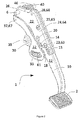
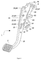
- Figure 1 shows a pedal assembly 60 comprising an adjustable brake pedal 1 suitable for motor vehicles according to the invention.
- the adjustable brake pedal 1 comprising a first body 10 including at one end a shoe 2, a second body 20 pivotable with respect to a rotating shaft 6, the first body 10 being coupled to the second body 20, and a third body 30 pivotably arranged with respect to the second body 20 and movably coupled with respect to the first body 10.
- the pedal assembly 60 comprises a support 7 wherein the pedal 1 is arranged coupled through the rotating shaft 6.
- the pedal 1 is suitable for the connection thereof to the rod (not depicted) of an actuator, preferably a servobrake.
- the third body 30 comprises a coupling 35 wherein said rod is pivotably coupled.
- the pedal 1 further comprises a control device 50 suitable for adjusting the position of the pedal 1 to the driver's needs, such that when the user steps on the shoe 2 he/she gets a sensation of homogeneity for all the adjustment positions of said pedal 1.
- the control device 50 shown in detail in Figure 4 , comprises a support 58 which is pivotably coupled to the second body 20, a screw 51 which is coupled at one end to the support 58, rotatable with respect to the support 58, and a threaded nut 56 movable along the screw 51 and pivotably coupled to the first body 10.
- the screw 51 can rotate with respect to the support 58 through a cable not shown in the drawings.
- the first body 10 and the second body 20 are arranged with respect to one another in a telescopic manner, the control device 50 being housed inside the first body and the second body 20.
- the control device 50 controls the distance between the rotating shaft 6 and the coupling 35, keeping the ratio of the distance between the rotating shaft 6 and the shoe 2 and the distance between the rotating shaft 6 and the coupling 35 of the third body 30 substantially constant.
- the first body 10 and the second body 20 comprise a substantially rectangular-shaped cross-section, respectively.
- both bodies 10 and 20 comprise a closed cross-section.
- Both bodies 10 and 20 are made of thin metal sheets, preferably having a thickness between about 1.0 mm and about 2.5 mm.
- the first body 10 is partially housed inside the second body 20, both bodies 10 and 20 being substantially coaxial to one another, the first body 10 being moved with respect to the second body 20 in a telescopic manner.
- the third body 30 comprises a substantially U-shaped cross-section, the first body 10 and the second body 20 being housed partially inside the third body 30.
- a more compact and lightweight pedal is thus obtained.
- the geometry of the second body 20 With the geometry of the second body 20, its moment of inertia is successfully increased with a reduced weight, improving the mechanical performance of the pedal 1.
- the control device 50 is protected inside the bodies 10, 20 and 30.
- the first body 10 comprises side walls 11 and 12 substantially parallel to one another and arranged facing one another, in each of which there is arranged at least one slot 13, 14 and 15 extending longitudinally to the first body 10, through which the first body 10 is movably coupled with respect to the second body 20.
- the second body 20 in turn comprises also side walls 21 and 22 substantially parallel to one another and arranged facing one another, comprising at least one hole 23, 24 and 25 in each side wall 21 and 22.
- the first body 10 is coupled to the second body 20 through a respective pivot 63, 64 and 65 which is inserted in the second body 20, traversing the slot 13, 14 and 15 and the corresponding hole 23, 24 and 25, such that the first body 10 can move with respect to the second body 20.
- the first body 10 comprises three slots 13, 14 and 15 arranged substantially parallel to one another, cooperating with the respective pivots 63, 64 and 65 that are inserted in the respective holes 23, 24 and 25 in the second body 20, the guiding of the telescopic movement being improved.
- slots 13 and 14 are substantially aligned with one another, as shown in the drawings.
- the second body 20 is housed in the support 7 of the pedal assembly 60, fixed to side walls 7b of the support 7 through the rotating shaft 6 which traverses the side walls 21 and 22 of the second body 20 through respective holes 26.
- the control device 50 is pivotably coupled to an end of the second body 20 through a pivot 68 traversing the support 58 of the control device 50 and a hole 28 arranged in each side wall 21 and 22 of the second body 20.
- the control device 50 is coupled to the first body 10 through the nut 56 which is coupled in a hole 16 arranged in each side wall 11 and 12 of the first body 10.
- the nut 56 comprises a projection 56b extending in a substantially orthogonal manner from each of the two surfaces 56a of the nut 56 that are substantially planar and arranged substantially parallel to one another. Both projections 56b are substantially aligned with one another and are inserted in the corresponding hole 16 of the first body 10, said hole being open to allow coupling the nut 56 to the first body 10.
- the screw 51 is longitudinally aligned with the first body 10 and the second body 20.
- the nut 56 is arranged on two supports in the body 10, particularly in both side walls 11 and 12 of the first body 10, stress distribution between both supports being improved.
- the third body 30 is pivotably coupled at one end to the second body 20 through a pivot 67 traversing the third body 30 and the second body 20 through the corresponding holes 37 and 27.
- the third body 30 is movably coupled at the opposite end to the first body 10.
- the first body 10 comprises an extension 18 which is housed inside the third body 30, and the third body 30 comprises a slot 33 in each side wall 31 and 32, both slots 33 arranged aligned with one another, a pin 61 and 62 being housed in the slot 33 traversing the slots 33 and the extension 18 through a corresponding hole 19, such that it allows the rotation of the third body 30 with respect to the second body 20 when the first body 10 is moved with respect to the second body 20 by means of the control device 50.
- the slot 33 of the third body 30 is a curvilinear slot.
- the driver When the driver needs to adapt the position of the pedal 1, particularly of the shoe 2, to his/her physical characteristics, he/she transmits a rotational movement to the screw 51 through an electrically- or manually-operated cable or through a motor directly coupled to the screw, both cable and motor not being depicted in the drawings.
- the screw 51 can rotate with respect to the support 58 of the control device 50, the screw 51 comprising means, which are known, to prevent sliding in both directions of rotation.
- the screw 51 causes the movement of the nut 56 and therefore of the first body 10 that moves telescopically with respect to the second body 20 by means of the slots 13, 14 and 15.
- the adjustment pedal 1 further comprises a cam 40 pivotably coupled at one end to the rotating shaft 6 through a corresponding hole 46 and movably coupled to the third body 30.
- the cam 40 comprises a contact surface 43 suitable for contacting a switch or a spring fixed in the pedal assembly, to that end it being necessary for the contact surface 43 to keep an absolute position constant with respect to the rotating shaft 6.
- the cam 40 comprises a slot 34 arranged in one of the side walls 31 of the third body 30, along which a projection 44 of the cam 40 moves.
- the cam 40 is arranged outside the third body 30 coupled to one of the side walls 31 of said third body 30.
- the projection 44 extends in a substantially orthogonal manner with respect to the cam 40.
- the slot 34 is a curvilinear slot (although it can be substantially straight in other embodiments) the geometry of which is calculated so that the contact surface 43 maintains its absolute position.
Landscapes
- Engineering & Computer Science (AREA)
- Physics & Mathematics (AREA)
- General Physics & Mathematics (AREA)
- Automation & Control Theory (AREA)
- Transportation (AREA)
- Mechanical Engineering (AREA)
- Mechanical Control Devices (AREA)
Priority Applications (2)
| Application Number | Priority Date | Filing Date | Title |
|---|---|---|---|
| EP13382498.7A EP2881833B1 (de) | 2013-12-09 | 2013-12-09 | Anpassbare Pedaleinheit für Kraftfahrzeuge |
| US14/563,915 US10017163B2 (en) | 2013-12-09 | 2014-12-08 | Adjustable pedal for motor vehicles |
Applications Claiming Priority (1)
| Application Number | Priority Date | Filing Date | Title |
|---|---|---|---|
| EP13382498.7A EP2881833B1 (de) | 2013-12-09 | 2013-12-09 | Anpassbare Pedaleinheit für Kraftfahrzeuge |
Publications (2)
| Publication Number | Publication Date |
|---|---|
| EP2881833A1 true EP2881833A1 (de) | 2015-06-10 |
| EP2881833B1 EP2881833B1 (de) | 2019-06-19 |
Family
ID=49885112
Family Applications (1)
| Application Number | Title | Priority Date | Filing Date |
|---|---|---|---|
| EP13382498.7A Active EP2881833B1 (de) | 2013-12-09 | 2013-12-09 | Anpassbare Pedaleinheit für Kraftfahrzeuge |
Country Status (2)
| Country | Link |
|---|---|
| US (1) | US10017163B2 (de) |
| EP (1) | EP2881833B1 (de) |
Families Citing this family (1)
| Publication number | Priority date | Publication date | Assignee | Title |
|---|---|---|---|---|
| US10988097B2 (en) * | 2019-04-03 | 2021-04-27 | GM Global Technology Operations LLC | Retractable pedal assembly for a vehicle |
Citations (5)
| Publication number | Priority date | Publication date | Assignee | Title |
|---|---|---|---|---|
| WO2000073099A1 (en) | 1999-06-01 | 2000-12-07 | Delphi Technologies, Inc. | Cam-guided adjustable pedal actuator assembly |
| EP1365303A1 (de) * | 2002-05-22 | 2003-11-26 | Batz, S. Coop. | Bremspedal- Nachstellungmechanismus |
| EP1365803A2 (de) | 2000-08-30 | 2003-12-03 | Oregon Health and Science University | Chemoschützende verbindung zur reduzierung der gastrischen toxizität von wirkstoffen |
| GB2443915A (en) * | 2006-10-25 | 2008-05-21 | Coutier Moulage Gen Ind | Adjustable pedal device for a motor vehicle |
| US20090025505A1 (en) * | 2007-07-24 | 2009-01-29 | Jason Allen Booher | Adjustable pedal system with ratio modifier |
Family Cites Families (7)
| Publication number | Priority date | Publication date | Assignee | Title |
|---|---|---|---|---|
| US5078024A (en) * | 1986-08-18 | 1992-01-07 | Comfort Pedals Inc. | Control pedal apparatus for a motor vehicle |
| US4989474A (en) * | 1986-08-18 | 1991-02-05 | Brecom Corporation | Control pedal apparatus for a motor vehicle |
| US5460061A (en) * | 1993-09-17 | 1995-10-24 | Comfort Pedals, Inc. | Adjustable control pedal apparatus |
| FR2821177B1 (fr) * | 2001-02-19 | 2003-04-25 | Peugeot Citroen Automobiles Sa | Pedale d'embrayage destinee a equiper un vehicule |
| DE10254585A1 (de) * | 2002-11-22 | 2004-06-09 | Fico Cables, S.A., Rubi | Pedal mit verstellbarer Position |
| KR100934994B1 (ko) * | 2008-03-10 | 2009-12-31 | 에스엘 주식회사 | 조절 가능한 페달 시스템 |
| US20150107401A1 (en) * | 2013-10-23 | 2015-04-23 | The U.S.A. As Represented By The Administrator Of The National Aeronautics And Space Administration | Pedal module for a vehicle having a control-by-wire system |
-
2013
- 2013-12-09 EP EP13382498.7A patent/EP2881833B1/de active Active
-
2014
- 2014-12-08 US US14/563,915 patent/US10017163B2/en active Active
Patent Citations (5)
| Publication number | Priority date | Publication date | Assignee | Title |
|---|---|---|---|---|
| WO2000073099A1 (en) | 1999-06-01 | 2000-12-07 | Delphi Technologies, Inc. | Cam-guided adjustable pedal actuator assembly |
| EP1365803A2 (de) | 2000-08-30 | 2003-12-03 | Oregon Health and Science University | Chemoschützende verbindung zur reduzierung der gastrischen toxizität von wirkstoffen |
| EP1365303A1 (de) * | 2002-05-22 | 2003-11-26 | Batz, S. Coop. | Bremspedal- Nachstellungmechanismus |
| GB2443915A (en) * | 2006-10-25 | 2008-05-21 | Coutier Moulage Gen Ind | Adjustable pedal device for a motor vehicle |
| US20090025505A1 (en) * | 2007-07-24 | 2009-01-29 | Jason Allen Booher | Adjustable pedal system with ratio modifier |
Also Published As
| Publication number | Publication date |
|---|---|
| US10017163B2 (en) | 2018-07-10 |
| EP2881833B1 (de) | 2019-06-19 |
| US20150158468A1 (en) | 2015-06-11 |
Similar Documents
| Publication | Publication Date | Title |
|---|---|---|
| US6782776B2 (en) | Adjustable pedal mechanism for a motor vehicle | |
| US7770487B2 (en) | Vehicle steering column structure | |
| US9003917B2 (en) | Adjustable shifter mechanism | |
| JP5076908B2 (ja) | ステアリングコラム装置 | |
| CA2876870C (en) | Variable speed control systems and methods for walk-behind working machines | |
| CN105873804B (zh) | 用于可调节踏板的保持恒定比例的可变比例机构 | |
| CN111169527B (zh) | 用于可调节转向柱组件的锁定装置 | |
| EP0289795A2 (de) | Teleskopische und kippbare Lenksäule | |
| CN108025759B (zh) | 具有车辆碰撞用的能量吸收器的用于机动车辆的可调节转向柱 | |
| US6763741B2 (en) | Adjustable foot-lever assembly | |
| EP2881833B1 (de) | Anpassbare Pedaleinheit für Kraftfahrzeuge | |
| JP4641432B2 (ja) | ハンドル装置 | |
| EP2081816B1 (de) | Individuell anpassbares pedalsystem für ein steuerungssystem eines luftfahrzeuges | |
| JP2004519765A (ja) | 乗物用のクラッチペダル及びこれを用いた自動車用のペダルボックスモジュール | |
| CN110397832B (zh) | 显示终端的旋转机构、安装总成和车辆 | |
| US20150198238A1 (en) | Shifter assembly | |
| NL2024919B1 (en) | Lever assist system for a motorcycle | |
| US11697447B2 (en) | Steering column positive lock drive mechanism | |
| EP1280034B1 (de) | Einstellvorrichtung zum Verstellen der Lage eines Pedals | |
| EP1365303B1 (de) | Bremspedal- Nachstellungmechanismus | |
| US7370554B2 (en) | Moveable control pedal assembly | |
| US20180244134A1 (en) | Apparatus for adjusting a windshield on a motor vehicle | |
| US7823479B2 (en) | Vehicle steering column structure | |
| US8960048B2 (en) | Accelerator pedal adjustment mechanism | |
| CN110139792B (zh) | 用于可调节转向柱的运动控制装置 |
Legal Events
| Date | Code | Title | Description |
|---|---|---|---|
| PUAI | Public reference made under article 153(3) epc to a published international application that has entered the european phase |
Free format text: ORIGINAL CODE: 0009012 |
|
| 17P | Request for examination filed |
Effective date: 20131209 |
|
| AK | Designated contracting states |
Kind code of ref document: A1 Designated state(s): AL AT BE BG CH CY CZ DE DK EE ES FI FR GB GR HR HU IE IS IT LI LT LU LV MC MK MT NL NO PL PT RO RS SE SI SK SM TR |
|
| AX | Request for extension of the european patent |
Extension state: BA ME |
|
| R17P | Request for examination filed (corrected) |
Effective date: 20151210 |
|
| RBV | Designated contracting states (corrected) |
Designated state(s): AL AT BE BG CH CY CZ DE DK EE ES FI FR GB GR HR HU IE IS IT LI LT LU LV MC MK MT NL NO PL PT RO RS SE SI SK SM TR |
|
| RIC1 | Information provided on ipc code assigned before grant |
Ipc: G05G 1/405 20080401AFI20140530BHEP |
|
| GRAP | Despatch of communication of intention to grant a patent |
Free format text: ORIGINAL CODE: EPIDOSNIGR1 |
|
| STAA | Information on the status of an ep patent application or granted ep patent |
Free format text: STATUS: GRANT OF PATENT IS INTENDED |
|
| INTG | Intention to grant announced |
Effective date: 20190319 |
|
| GRAS | Grant fee paid |
Free format text: ORIGINAL CODE: EPIDOSNIGR3 |
|
| GRAA | (expected) grant |
Free format text: ORIGINAL CODE: 0009210 |
|
| STAA | Information on the status of an ep patent application or granted ep patent |
Free format text: STATUS: THE PATENT HAS BEEN GRANTED |
|
| AK | Designated contracting states |
Kind code of ref document: B1 Designated state(s): AL AT BE BG CH CY CZ DE DK EE ES FI FR GB GR HR HU IE IS IT LI LT LU LV MC MK MT NL NO PL PT RO RS SE SI SK SM TR |
|
| REG | Reference to a national code |
Ref country code: GB Ref legal event code: FG4D |
|
| REG | Reference to a national code |
Ref country code: CH Ref legal event code: EP |
|
| REG | Reference to a national code |
Ref country code: IE Ref legal event code: FG4D |
|
| REG | Reference to a national code |
Ref country code: AT Ref legal event code: REF Ref document number: 1146312 Country of ref document: AT Kind code of ref document: T Effective date: 20190715 |
|
| REG | Reference to a national code |
Ref country code: DE Ref legal event code: R096 Ref document number: 602013056743 Country of ref document: DE |
|
| REG | Reference to a national code |
Ref country code: NL Ref legal event code: MP Effective date: 20190619 |
|
| PG25 | Lapsed in a contracting state [announced via postgrant information from national office to epo] |
Ref country code: NO Free format text: LAPSE BECAUSE OF FAILURE TO SUBMIT A TRANSLATION OF THE DESCRIPTION OR TO PAY THE FEE WITHIN THE PRESCRIBED TIME-LIMIT Effective date: 20190919 Ref country code: FI Free format text: LAPSE BECAUSE OF FAILURE TO SUBMIT A TRANSLATION OF THE DESCRIPTION OR TO PAY THE FEE WITHIN THE PRESCRIBED TIME-LIMIT Effective date: 20190619 Ref country code: LT Free format text: LAPSE BECAUSE OF FAILURE TO SUBMIT A TRANSLATION OF THE DESCRIPTION OR TO PAY THE FEE WITHIN THE PRESCRIBED TIME-LIMIT Effective date: 20190619 Ref country code: AL Free format text: LAPSE BECAUSE OF FAILURE TO SUBMIT A TRANSLATION OF THE DESCRIPTION OR TO PAY THE FEE WITHIN THE PRESCRIBED TIME-LIMIT Effective date: 20190619 Ref country code: SE Free format text: LAPSE BECAUSE OF FAILURE TO SUBMIT A TRANSLATION OF THE DESCRIPTION OR TO PAY THE FEE WITHIN THE PRESCRIBED TIME-LIMIT Effective date: 20190619 Ref country code: HR Free format text: LAPSE BECAUSE OF FAILURE TO SUBMIT A TRANSLATION OF THE DESCRIPTION OR TO PAY THE FEE WITHIN THE PRESCRIBED TIME-LIMIT Effective date: 20190619 |
|
| REG | Reference to a national code |
Ref country code: LT Ref legal event code: MG4D |
|
| PG25 | Lapsed in a contracting state [announced via postgrant information from national office to epo] |
Ref country code: LV Free format text: LAPSE BECAUSE OF FAILURE TO SUBMIT A TRANSLATION OF THE DESCRIPTION OR TO PAY THE FEE WITHIN THE PRESCRIBED TIME-LIMIT Effective date: 20190619 Ref country code: GR Free format text: LAPSE BECAUSE OF FAILURE TO SUBMIT A TRANSLATION OF THE DESCRIPTION OR TO PAY THE FEE WITHIN THE PRESCRIBED TIME-LIMIT Effective date: 20190920 Ref country code: BG Free format text: LAPSE BECAUSE OF FAILURE TO SUBMIT A TRANSLATION OF THE DESCRIPTION OR TO PAY THE FEE WITHIN THE PRESCRIBED TIME-LIMIT Effective date: 20190919 Ref country code: RS Free format text: LAPSE BECAUSE OF FAILURE TO SUBMIT A TRANSLATION OF THE DESCRIPTION OR TO PAY THE FEE WITHIN THE PRESCRIBED TIME-LIMIT Effective date: 20190619 |
|
| REG | Reference to a national code |
Ref country code: AT Ref legal event code: MK05 Ref document number: 1146312 Country of ref document: AT Kind code of ref document: T Effective date: 20190619 |
|
| PG25 | Lapsed in a contracting state [announced via postgrant information from national office to epo] |
Ref country code: SK Free format text: LAPSE BECAUSE OF FAILURE TO SUBMIT A TRANSLATION OF THE DESCRIPTION OR TO PAY THE FEE WITHIN THE PRESCRIBED TIME-LIMIT Effective date: 20190619 Ref country code: EE Free format text: LAPSE BECAUSE OF FAILURE TO SUBMIT A TRANSLATION OF THE DESCRIPTION OR TO PAY THE FEE WITHIN THE PRESCRIBED TIME-LIMIT Effective date: 20190619 Ref country code: RO Free format text: LAPSE BECAUSE OF FAILURE TO SUBMIT A TRANSLATION OF THE DESCRIPTION OR TO PAY THE FEE WITHIN THE PRESCRIBED TIME-LIMIT Effective date: 20190619 Ref country code: NL Free format text: LAPSE BECAUSE OF FAILURE TO SUBMIT A TRANSLATION OF THE DESCRIPTION OR TO PAY THE FEE WITHIN THE PRESCRIBED TIME-LIMIT Effective date: 20190619 Ref country code: CZ Free format text: LAPSE BECAUSE OF FAILURE TO SUBMIT A TRANSLATION OF THE DESCRIPTION OR TO PAY THE FEE WITHIN THE PRESCRIBED TIME-LIMIT Effective date: 20190619 Ref country code: AT Free format text: LAPSE BECAUSE OF FAILURE TO SUBMIT A TRANSLATION OF THE DESCRIPTION OR TO PAY THE FEE WITHIN THE PRESCRIBED TIME-LIMIT Effective date: 20190619 Ref country code: PT Free format text: LAPSE BECAUSE OF FAILURE TO SUBMIT A TRANSLATION OF THE DESCRIPTION OR TO PAY THE FEE WITHIN THE PRESCRIBED TIME-LIMIT Effective date: 20191021 |
|
| PG25 | Lapsed in a contracting state [announced via postgrant information from national office to epo] |
Ref country code: IS Free format text: LAPSE BECAUSE OF FAILURE TO SUBMIT A TRANSLATION OF THE DESCRIPTION OR TO PAY THE FEE WITHIN THE PRESCRIBED TIME-LIMIT Effective date: 20191019 Ref country code: IT Free format text: LAPSE BECAUSE OF FAILURE TO SUBMIT A TRANSLATION OF THE DESCRIPTION OR TO PAY THE FEE WITHIN THE PRESCRIBED TIME-LIMIT Effective date: 20190619 Ref country code: SM Free format text: LAPSE BECAUSE OF FAILURE TO SUBMIT A TRANSLATION OF THE DESCRIPTION OR TO PAY THE FEE WITHIN THE PRESCRIBED TIME-LIMIT Effective date: 20190619 Ref country code: ES Free format text: LAPSE BECAUSE OF FAILURE TO SUBMIT A TRANSLATION OF THE DESCRIPTION OR TO PAY THE FEE WITHIN THE PRESCRIBED TIME-LIMIT Effective date: 20190619 |
|
| PG25 | Lapsed in a contracting state [announced via postgrant information from national office to epo] |
Ref country code: TR Free format text: LAPSE BECAUSE OF FAILURE TO SUBMIT A TRANSLATION OF THE DESCRIPTION OR TO PAY THE FEE WITHIN THE PRESCRIBED TIME-LIMIT Effective date: 20190619 |
|
| PG25 | Lapsed in a contracting state [announced via postgrant information from national office to epo] |
Ref country code: DK Free format text: LAPSE BECAUSE OF FAILURE TO SUBMIT A TRANSLATION OF THE DESCRIPTION OR TO PAY THE FEE WITHIN THE PRESCRIBED TIME-LIMIT Effective date: 20190619 Ref country code: PL Free format text: LAPSE BECAUSE OF FAILURE TO SUBMIT A TRANSLATION OF THE DESCRIPTION OR TO PAY THE FEE WITHIN THE PRESCRIBED TIME-LIMIT Effective date: 20190619 |
|
| PG25 | Lapsed in a contracting state [announced via postgrant information from national office to epo] |
Ref country code: IS Free format text: LAPSE BECAUSE OF FAILURE TO SUBMIT A TRANSLATION OF THE DESCRIPTION OR TO PAY THE FEE WITHIN THE PRESCRIBED TIME-LIMIT Effective date: 20200224 |
|
| REG | Reference to a national code |
Ref country code: DE Ref legal event code: R097 Ref document number: 602013056743 Country of ref document: DE |
|
| PLBE | No opposition filed within time limit |
Free format text: ORIGINAL CODE: 0009261 |
|
| STAA | Information on the status of an ep patent application or granted ep patent |
Free format text: STATUS: NO OPPOSITION FILED WITHIN TIME LIMIT |
|
| PG2D | Information on lapse in contracting state deleted |
Ref country code: IS |
|
| REG | Reference to a national code |
Ref country code: CH Ref legal event code: PL |
|
| 26N | No opposition filed |
Effective date: 20200603 |
|
| REG | Reference to a national code |
Ref country code: BE Ref legal event code: MM Effective date: 20191231 |
|
| PG25 | Lapsed in a contracting state [announced via postgrant information from national office to epo] |
Ref country code: MC Free format text: LAPSE BECAUSE OF FAILURE TO SUBMIT A TRANSLATION OF THE DESCRIPTION OR TO PAY THE FEE WITHIN THE PRESCRIBED TIME-LIMIT Effective date: 20190619 Ref country code: SI Free format text: LAPSE BECAUSE OF FAILURE TO SUBMIT A TRANSLATION OF THE DESCRIPTION OR TO PAY THE FEE WITHIN THE PRESCRIBED TIME-LIMIT Effective date: 20190619 |
|
| GBPC | Gb: european patent ceased through non-payment of renewal fee |
Effective date: 20191209 |
|
| PG25 | Lapsed in a contracting state [announced via postgrant information from national office to epo] |
Ref country code: LU Free format text: LAPSE BECAUSE OF NON-PAYMENT OF DUE FEES Effective date: 20191209 Ref country code: FR Free format text: LAPSE BECAUSE OF NON-PAYMENT OF DUE FEES Effective date: 20191231 Ref country code: GB Free format text: LAPSE BECAUSE OF NON-PAYMENT OF DUE FEES Effective date: 20191209 Ref country code: IE Free format text: LAPSE BECAUSE OF NON-PAYMENT OF DUE FEES Effective date: 20191209 |
|
| PG25 | Lapsed in a contracting state [announced via postgrant information from national office to epo] |
Ref country code: BE Free format text: LAPSE BECAUSE OF NON-PAYMENT OF DUE FEES Effective date: 20191231 Ref country code: LI Free format text: LAPSE BECAUSE OF NON-PAYMENT OF DUE FEES Effective date: 20191231 Ref country code: CH Free format text: LAPSE BECAUSE OF NON-PAYMENT OF DUE FEES Effective date: 20191231 |
|
| PG25 | Lapsed in a contracting state [announced via postgrant information from national office to epo] |
Ref country code: CY Free format text: LAPSE BECAUSE OF FAILURE TO SUBMIT A TRANSLATION OF THE DESCRIPTION OR TO PAY THE FEE WITHIN THE PRESCRIBED TIME-LIMIT Effective date: 20190619 |
|
| PG25 | Lapsed in a contracting state [announced via postgrant information from national office to epo] |
Ref country code: MT Free format text: LAPSE BECAUSE OF FAILURE TO SUBMIT A TRANSLATION OF THE DESCRIPTION OR TO PAY THE FEE WITHIN THE PRESCRIBED TIME-LIMIT Effective date: 20190619 Ref country code: HU Free format text: LAPSE BECAUSE OF FAILURE TO SUBMIT A TRANSLATION OF THE DESCRIPTION OR TO PAY THE FEE WITHIN THE PRESCRIBED TIME-LIMIT; INVALID AB INITIO Effective date: 20131209 |
|
| PG25 | Lapsed in a contracting state [announced via postgrant information from national office to epo] |
Ref country code: MK Free format text: LAPSE BECAUSE OF FAILURE TO SUBMIT A TRANSLATION OF THE DESCRIPTION OR TO PAY THE FEE WITHIN THE PRESCRIBED TIME-LIMIT Effective date: 20190619 |
|
| PGFP | Annual fee paid to national office [announced via postgrant information from national office to epo] |
Ref country code: DE Payment date: 20251229 Year of fee payment: 13 |